1
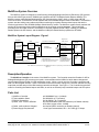
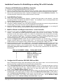
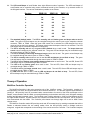
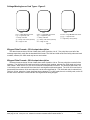
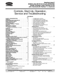
Installation Manual - 6000-900 Rev F
MultiProx Controller - 6000A
____________________________________________________________________________________________________
HID Corporation 9292 Jeronimo Road Irvine, CA 92618 USA TEL (949) 598-1600 (800) 237-7769 FAX (949) 598-1690
Web page, E-mail - www.prox.com - MultiProx Controller Installation Manual 6000-900 Rev F
1 of 27
Table of Contents
MultiProx System Overview ...................................................................................................... 4
MultiProx System Layout Diagram - Figure 1 ....................................................................................4
Description/Operation ............................................................................................................... 4
Parts List..................................................................................................................................... 4
Installation Procedure For Retrofitting an existing 708 or 808 Controller ............................ 5
1. Replace old 708/808 with new MultiProx Controller......................................................................5
2. Install MultiProx Readers ................................................................................................................5
3. MultiProx Reader and Wiegand connections - at the Controller..................................................5
4. Configure the DIP switches SW1 SW2, SW3 and SW4 .................................................................5
5. Install MultiProx HSM(s) if required................................................................................................6
6. HSM configuration - at the Controller ............................................................................................6
7. Connect power, test system ...........................................................................................................7
Troubleshooting Guide ............................................................................................................. 7
1. Slow read speed .............................................................................................................................7
2. Low read range................................................................................................................................7
3. No Card Read...................................................................................................................................8
4. Improper HSM response .................................................................................................................8
5. Optimize performance for Schlage card reads .............................................................................8
6. Optional Led and Beeper configurations.....................................................................................10
Theory of Operation................................................................................................................. 11
MultiProx Controller Operation.........................................................................................................11
MultiProx Reader Operation .............................................................................................................11
Schlage/Westinghouse (SE) “Command key” Operation ...............................................................11
MultiProx HSM operation ..................................................................................................................12
Schlage/Westinghouse Card Types - Figure 2 ................................................................................12
Wiegand Data Formats - 32 bit output description .........................................................................12
Wiegand Data Formats - 26 bit output description .........................................................................12
Schlage 1030 Card 32 bit Output Format.........................................................................................13
Schlage 1030 card 26 bit Output Format .........................................................................................13
Schlage 1040 Card 32 bit Output Format.........................................................................................13
Schlage 1040 Card 26 bit Output Format.........................................................................................14
Schlage 1050 Card 32 bit Output Format.........................................................................................14
Schlage 1050 Card 26 bit Output Format.........................................................................................15
Wiegand Format Components....................................................................................................................... 15
Access Control panel - converting external octal number to “system reporting number”................................. 16
Installation Aid Diagrams ........................................................................................................ 17
MultiProx Controller Switch Settings - Figure 3 ..............................................................................17
MultiProx Controller - Connectors, Relay and Jumper Positions - Figure 4 .................................18
MultiProx Controller Dimensions - Figure 5.....................................................................................19
Installation notes for mounting the 5385AGS (side) or B (back) Reader.......................................20
MultiProx Reader Dimensions - Figure 6 .........................................................................................20
MultiProx HSM Dimension Diagram - Figure 7 ................................................................................21
MultiProx HSM Wiring Description - Figure 8 ..................................................................................21
Decimal to Binary Conversion Table for facility codes 0 to 511 - Figure 9 ...................................22
Specifications for MultiProx system ...................................................................................... 25
Controller - Model No. 6000ANN00 ...................................................................................................25
____________________________________________________________________________________________________
HID Corporation 9292 Jeronimo Road Irvine, CA 92618 USA TEL (949) 598-1600 (800) 237-7769 FAX (949) 598-1690
Web page, E-mail - www.prox.com - MultiProx Controller Installation Manual 6000-900 Rev F
2 of 27
MultiProx Reader - model no. 5385AGB00 (back) or 5385AGS00 (side)........................................26
HSM model no. 6020ANC00 ..............................................................................................................27
____________________________________________________________________________________________________
HID Corporation 9292 Jeronimo Road Irvine, CA 92618 USA TEL (949) 598-1600 (800) 237-7769 FAX (949) 598-1690
Web page, E-mail - www.prox.com - MultiProx Controller Installation Manual 6000-900 Rev F
3 of 27
MultiProx System Overview
The MultiProx system is designed to retrofit existing Schlage/Westinghouse Security Electronics (SE) systems
that use 2814/2815 type sensors, 708/808 type Controllers and SE774 Multiple Switch Monitors MSM(s). The
MultiProx system reads Schlage/Westinghouse (SE) Command Keys (1030, 1040, or 1050) along with HID
ProxCard II Cards. It interfaces to all host systems that have standard Wiegand electrical interfaces. The MultiProx
system uses the existing coax cable and provides monitoring input points and associated outputs that are the
functional equivalent of the SE MSM (Multiple Switch Monitor) module. The MultiProx system directly replaces the
existing SE components without major modifications to the existing mounting hardware. This includes the
mounting holes and cable locations. The MultiProx Controller replaces the SE 708(S) or 808(S), the MultiProx
Reader replaces the SE Sensors, and the MultiProx HSM (HID Switch Monitor) replaces the SE MSM.
MultiProx System Layout Diagram - Figure 1
Wiegand and
Relay outputs
READERS
HSMS
M/N 862814/
862815
P/N 5385AGB00/
5385AGS00
coax*
M/N 86744
MULTIPROX CONTROLLER
Reader
Channel 1
Reader 1 data **
TBW1
coax*
P/N 6020ANC00
M/N 86808
P/N 6000ANN00
Reader 8 data **
TBW8
TBR1
TBR8
M/N 862814/
862815
P/N 5385AGB00/
5385AGS00
coax*
M/N86744
Reader
Channel 8
P/N 6020ANC00
coax*
Maximum - 8 Reader Channels
NEW
SYSTEM
HSM 1 relay outputs***
Access
Control
Panel
HSM 8 relay outputs***
Wiegand Interface
TBW1-TBW8
pin 1) Data "0"
pin 2) Data "1"
pin 3) Data Return
* - existing RG/6 Coax
pin 4) GREEN LED Control
** - Alpha 1295 or Equivalent per channel pin 5) RED LED Control
pin 6) Beeper Control
*** - Alpha 1292 or Equiv. per output
Access
Control
System
Host
Note - HSMs are only required when input (REX/Door Sense/ Aux. inputs) wiring is local to the reader door.
Figure 1
Description/Operation
The MultiProx Controller is the center of the MultiProx system. The Controller scans the Readers for HID or
Schlage/Westinghouse (SE) access control cards, communicates with the HSMs for switch status changes and
communicates with the Reader for LED and Beeper control. When a card is read, the Controller outputs the card
data over the Wiegand interface. When a monitored contact has a status change, the Controller switches the relay
output that provides status of the HSM monitored switch that changed. See Figure 1. The Controller has a default
mode for controlling the Reader beeper and LEDs, as well as an external (Host) controlled beeper and LED option.
Parts List
1) MultiProx Controller
2) This Installation Sheet
3) RS3222 Screwdriver
3) Cable, coax - RG/6 or SE 9284
4) Cable, multi-conductor Wiegand
5) Power Supply Requirements
p/n 6000ANN00 qty 1 (included)
p/n 6000-900 qty 1 (included)
p/n 68-0002-01 qty 1 (included)
As required/installed (1000 feet maximum per Reader channel)
65% shield, copper center, 18AWG
As required (500 ft maximum per Reader channel)
Linear type recommended, 20.0 - 28.5 VDC @ 2.0 Amps
____________________________________________________________________________________________________
HID Corporation 9292 Jeronimo Road Irvine, CA 92618 USA TEL (949) 598-1600 (800) 237-7769 FAX (949) 598-1690
Web page, E-mail - www.prox.com - MultiProx Controller Installation Manual 6000-900 Rev F
4 of 27
Installation Procedure For Retrofitting an existing 708 or 808 Controller
1.Replace old 708/808 with new MultiProx Controller
1a. Locate the existing Schlage/Westinghouse (SE) Controller.
1b. Remove coax cables from Sensors, cables from door lock outputs, power supply and terminal connections.
Mark coax cables with Reader channel locations, and all other wires with their functions for future reference.
1c. Remove SE components and put aside. Replace the 708/808 Controller with the MultiProx Controller. The
mounting holes are located in the same positions as the SE Controller.
2. Install MultiProx Readers
2a. Locate existing Schlage/Westinghouse Sensor(s). Determine their type (back or side mounted). Verify that
the existing location is suitable for the MultiProx Reader. See Installation notes for mounting Readers and
MultiProx Reader dimensions - Figure 6.
2b. the coax cable from the SE Sensor. Remove the SE Sensors.
2c. Connect the MultiProx Reader to the coax cable (hand tight) and insulate the connector using electrical tape
or shrink tubing. Do not use wrenches or pliers to tighten the coax connectors.
2d. Mount the MultiProx Reader. Use the hardware that comes with the MultiProx Reader or use existing SE
hardware. For more information see the MultiProx Reader installation guide (5385-900).
3. MultiProx Reader and Wiegand connections - at the Controller
3a. Connect the coax cables to the MultiProx Controller. Note which channels are connected to each Reader
location. The Reader coax channel numbers are labeled on the top cover of the Controller. The Coax
connectors are the same type as a typical TV or cable TV connection that uses 75 ohm RG/6 coax cable.
The cable connectors are called “F” type and are commonly available in electrical supply stores as “F-56
crimp-on connectors for RG/6 cable”. A crimping tool is required. Follow the directions that come with the
connectors and crimp tools. Twist-on types are also available, but are less reliable.
3b. Connect the Wiegand interface cables using the supplied removable 6 pin terminal strips. Connect the
Wiegand interface cables to the Access Control Panel. The terminal strips are labeled TBW1 to TBW8.
Reader channel one corresponds to TBW1, Reader channel two corresponds to TBW2, and so on.
3d. Wiegand terminal strips accept up to 18AWG wire. Use the small screwdriver provided to secure each wire
into its terminal strip location. The terminal strips are removable to facilitate attaching the signal wires. Their
signal names are marked on the Controller board, near each connector. See MultiProx Controller Connectors, Relay and Jumper Positions Figure 4. The terminal strip connections are also shown in the
following table:
TBW(1-8) PIN NUMBER SIGNAL TYPICAL WIRE COLOR
1
DATA “0” GREEN
2
DATA “1” WHITE
3
DATA RETURN DRAIN WIRE
4
GREEN LED ORANGE
5
RED LED BROWN
6
BEEPER YELLOW
4. Configure the DIP switches SW1 SW2, SW3 and SW4
Note: Following each change of dip switch settings for SW1, SW2, SW3 or SW4, the unit must be reset by
powering down then up again before the new switch setting will take affect.
4a. See the Schlage/Westinghouse Card description diagram - Figure 2. To identify the card type, count the
number of digits printed on the SE card. 5 digit card numbers are 1030’s, 6 digit cards are 1040’s, and 8 digit
are 1050’s. Select Card Type on SW4, switch 6 and 7 for either 1030, 1040 or 1050. 1050 is the default
setting. See the MultiProx Switch settings - Figure 3.
4b. If the card type is 1050, ignore the Main facility, Alternate facility and Card letter switch settings and go to
paragraph (4d). If the type of card is a 1030 or 1040, set the Main Facility Code Letter on SW4 switch 2
and 3 and Main Facility Code Number on SW4 switch 1 and SW3 switch 1-8. The switches are to be set for
the binary representation of the facility code number printed on the cards. See the MultiProx Switch
settings Figure 3 and the Decimal to Binary Conversion Chart - Figure 9.
____________________________________________________________________________________________________
HID Corporation 9292 Jeronimo Road Irvine, CA 92618 USA TEL (949) 598-1600 (800) 237-7769 FAX (949) 598-1690
Web page, E-mail - www.prox.com - MultiProx Controller Installation Manual 6000-900 Rev F
5 of 27
4c. If two facility codes are used, set the Alternate Facility Code Letter on SW2 switches 2 and 3. Also set the
Alternate Facility Code Number on SW2 switch 1 and SW1, switch 1-8. The switches are to be set for the
binary representation of the Facility Code Number printed on the cards. See the MultiProx Switch settings
Figure 3 and the Decimal to Binary Conversion Chart - Figure 9.
4d. Select the Number of Reader Channels used on SW2 switch 6 and 7. The options are 1, 2, 4 or 8,
meaning, Channel 1 active, Channels 1 and 2 active, Channels 1 through 4 active or Channels 1 through 8
active. The default is channels 1 through 8 active, with switch 6 and 7 are in the “on” position. See the
MultiProx Switch settings - Figure 3.
5. Install MultiProx HSM(s) if required.
5a. The SE MSMs (Multiple Switch Monitor) can be located anywhere between the Controller and the Reader.
Locate each SE MSM. Remove the Coax cable and dismount the unit. Remove the screws that secure the
back plate.
5b. Remove the MSM printed circuit board by loosening the nuts on the coax connectors, end screws on the
terminal block and mounting screws internal to the MSM housing.
5c. Pull the MSM printed circuit board from the housing. Pigtails on the terminal block are inserted into sockets
on the printed circuit card. Use caution not to break the pigtails on the terminal block.
5d. Set the jumper at J1 to NRD (pins 1 and 2) when the HSM is not connected to a Reader or RD (pins 2 and 3)
when connected to a Reader.
5e. Place the HSM into the housing by fitting the pigtails of the terminal block into the respective socket of the
HSM printed circuit board. The coax connectors will fit directly into the existing holes.
5f. Replace the internal mounting screws, the end screws on the terminal block and the coax connector nuts.
5g. Attach the coax cables (hand tight) to both connectors. It does not matter which connector is used to connect
the Reader and Controller.
5h. Each monitored contact requires a 36K ohm resistor across the HSM input. The SE MSM requires the same
termination resistance. The connections to the monitored switches and their termination resistors are not
affected and do not require rewiring or reconfiguration. See the HSM Wiring Description - Figure 8.
6. HSM configuration - at the Controller
6a. If there are no HSM’s in the system, be sure the HSM switch (SW2 switch 8) is off. If there are HSM’s, Be
sure HSM SW2 switch 8 is on. Determine which channel the Reader and the HSM are to be connected. Four
relays will be packaged with each HSM’s accessory kit. Install the relays on the Controller in the associated
sockets for the channel. The 6 pin relay sockets and 8 pin terminal connections are marked for the
respective channel. For example, the channel 1 relays are marked RLY1A, RLY1B, RLY1C and RLY1D and
the terminal is marked TBR1. For channel 2 the relays are marked RLY2A, RLY2B, RLY2C and RLY2D and
the terminal is marked TBR2. A maximum of 32 relays (4 for each channel) can be installed. See the
MultiProx Controller - Connectors, Relays and Jumper Positions - Figure 4.
6b. To connect the inputs of the Access Control Panel to the terminal connector for the relay outputs, each relay
will require 2 wires. For example, if channel 1, relay “A” is used, connect one wire to the TBR1-RLYA pin and
connect one to the TBR1-COM-A pin. The COM-A pin is the common contact of the relay. Relays A, B, C
and D correspond to MSM inputs 4, 3, 2 and 1 respectively. See the HSM Wiring Description - Figure 8.
Consult the Access Control Panel installation guidelines for the correct contact configuration alarm state normally open or normally closed.
6c. Set the relay contact configuration for either normally open or normally closed contacts using the
shunt/jumper provided in the HSM accessory kit. The jumper positions are marked J1A through J8D on the
Controller for the respective channel and relay. Note: The relay contact configuration refers to the
“alarm” state of the monitored switch. Place the shunts/jumpers across the jumper pins “NC” for contacts
that are normally closed in the alarm condition and place the jumpers across the “NO” for contacts that are
normally open in the alarm condition. The jumper setting will then be set so the relay contacts follow the
switch contacts. When power is on, the relays on the Controller are energized in the normal/non alarm state,
so a power shutdown causes them to go to the alarm state.
6d. On the Controller, place the HSM switch 8 of SW2 to the “on” position. Also see MultiProx HSM Installation
Guide (6020-900)
____________________________________________________________________________________________________
HID Corporation 9292 Jeronimo Road Irvine, CA 92618 USA TEL (949) 598-1600 (800) 237-7769 FAX (949) 598-1690
Web page, E-mail - www.prox.com - MultiProx Controller Installation Manual 6000-900 Rev F
6 of 27
7. Connect power, test system
7a. Connect the 24VDC power cables to TB1. See Controller - Connectors, Relays and Jumper Positions Figure 4. Pin 1 is the Ground terminal (-) and Pin 2 is the +24 VDC terminal (+). See cautions:
Cautions: Never connect the wires while the power is on. The +24VDC terminal is very close to the
Controllers’ metal housing, making it very easy to short out the power supply with an non-insulated
screwdriver. Care should be taken not to reverse the polarity on the power supply to the Controller as
damage can occur. Also, always connect all system grounds together at one point - preferably at the power
supply. Make sure all system components are grounded properly before applying power to any of them. This
applies to the MultiProx Controller, Host panel, Wiegand interface modules or converters (if any), and any
other peripheral components.
7b. Once the MultiProx Reader(s), HSM(s) and Controller are wired together, configured and powered, the system
can be tested. If the LED and beeper switch settings are still in the default positions, the LED on each
Reader will be red and the LED should flash and the beeper should beep when you present a card.
7c. Test the HSMs by opening (if normally closed), or shorting (if normally open) the input contacts and verifying
the respective output is activated.
Troubleshooting Guide
1. Slow read speed
1a. The system will always read/report a card read within 2 seconds, even under the worst case condition. The
response time may depend on how the LEDs and Beeper are configured. If they are controlled by the host,
the response time is the reading/reporting time plus the host system response time.
1b. Make sure the HSM switch is off (SW2, position 8). This will speed up the system by 1/3.
1c. The MultiProx system must share the time between reading Schlage cards and reading HID cards. If you are
accustomed to the Schlage system and are now using the MultiProx system, the response may be slower
especially if the Schlage system was using 4 channel Controllers.
1d. The method of presenting the card is very important. Present the Schlage card in the center of the Reader
and hold it there momentarily while the reading is taking place. Swiping the card across the face of the
Reader is not recommended.
1e. The Schlage card will read up to 3 inches. See the Optimized performance for Schlage card reads - below.
For quick and accurate reads, it is best to hold the card away from the face of the Reader about ½ inch for
the best performance. If you press the card directly onto the face of the Reader, the tuned circuits can get
de-tuned, distorting the hit information transmitted by the card. Also, any of the situations listed in the next
section, Low read range, can cause the read speed to appear slow.
2. Low read range
2a. Mounting the Reader on or near any metal objects will result in a reduction of read range. If metal is
unavoidable, then a minimum of two inch spacing should be maintained between the Reader and the metal
surface. Contact HID customer service to inquire about the availability of 2 inch spacers that fit the
MultiProx Reader.
2b. Placing the reader in a noisy RF environment will also result in a reduced read range. Sources of this noise
include, but are not limited to, computer monitors, AC wiring, radios, televisions, cellular phones, printers, fax
machines, motors and generators.
2c. A switching power supply can create noise affecting both the Readers ability to read cards and its read range.
Linear supplies are recommended because they filter RF noise out of the 24 VDC connection.
2d. A power supply that is less than the recommended 24 volt, 2 Amp capacity, may not be able to drive enough
current. This can result in a reduced read range.
2e. Care should be taken to only hand tighten coax connections. The Reader antenna wires can become twisted
or broken if too much torque is applied to the coax connector. See Troubleshooting Guide - optimized
performance for Schlage card reads below.
2f. Mounting readers to tinted glass may result in reduced read range for Schlage cards.
2g. Readers mounted behind non-metallic surfaces such as a wall may have low read range. In extreme cases
contact technical support for the possibility of acquiring a customized reader.
____________________________________________________________________________________________________
HID Corporation 9292 Jeronimo Road Irvine, CA 92618 USA TEL (949) 598-1600 (800) 237-7769 FAX (949) 598-1690
Web page, E-mail - www.prox.com - MultiProx Controller Installation Manual 6000-900 Rev F
7 of 27
3. No Card Read
If there is a constant amber LED:
3a. Check that the coax connectors on the Controller, Reader and HSM connections are properly and tightly
secured thus making good electrical contact.
3b. Check the integrity of the coax cable. Check for continuity or broken center leads.
3c. Check that the appropriate channels are enabled on the Controller. This is done through dip switch SW2
switches 6 and 7. See MultiProx Switch Settings - Figure 3.
If there is a constant red LED no beep or green LED flash:
3d. Make sure Controller is properly configured for the particular Card Type is set correctly to match the type of
SE card that is being presented to the Reader - 1030, 1040 or 1050. This is done through the DIP switch
settings SW4 switches 6 and 7. See MultiProx Switch Settings - Figure 3.
3e. Check that the Controller is configured for the correct Card Letter and Facility Code(s). This is controlled
through the DIP switches SW4 switches 1 through 3 and SW3 switches 1 through 8.
3f. Check DIP switches SWB, SWG and SWR to ensure that the beeper and LED are properly enabled or
disabled on each channel for the particular application.
3g. Make sure that when the card is presented to the Reader the front of the card is parallel to the Reader face.
Care should be taken not to move the card into or out of the field too quickly. SE cards tend to read well in
one spot on the Reader; if one spot will not read, try another.
4. Improper HSM response
4a. Check to see if the HSM is properly connected and making good electrical contact.
4b. Check that the HSM enable switch - SW2 switch 1 is on.
4c. If the Controller relays begin cycling on and off, check that the shunt jumper on the HSM is in the proper place
- “NRD” when no Reader is attached to the HSM or “RD” when a Reader is attached to the HSM.
Note: Following each change of dip switch settings for SW1, SW2, SW3 or SW4, the unit must be reset by
re-powering it before the new switch setting will take affect.
5. Optimize performance for Schlage card reads
5a. If you have a terminal with a serial port, the read performance can be monitored and adjusted for optimal
performance. You will need:
• A terminal (Dumb terminal, PC, laptop, etc.)
• A communications program for RS232 serial port applications
• A 9 pin male to 9 or 25 pin female cable (depending on your terminal)
• An extension coax cable with “F-type barrel connector (optional)
• The small insulated screwdriver (provided with the Controller)
• A small Philips head screwdriver
• A DC Voltmeter
Connect the 9 pin serial cable (male end) to the MultiProx Controller serial port and the other (female) end to
the terminals’ Com1 or Com2 port. Set the terminal programs’ serial Communication mode settings to Com1
or Com2, 9600, N, 8, 2. To test the connection, the MultiProx Controller will transmit a message when power
is applied. The message will appear as follows:
MultiProx 501-05 Copyright (c) 1994-1996 HID Corporation
5b. Once this message is observed, the terminal and terminal program you are using is set-up correctly. To start
the Controller messages, press “1” on the terminal key board, and card numbers will be displayed each time a
card is read. The format is “Card type, Channel #, Card #”. HID Prox and Schlage cards will appear as
follows:
PROX CH 1 20 4CA064F
1050 CH 1 15712643
5c. Pressing “2” will output card numbers along with additional information for SE cards. The data will represent
the data for the 4 or 5 tuned circuit responses (hits) referred to in Theory of Operation. A typical output will
look as follows:
1050 CH 1 15712643 10 5 1 1638 20 953 28 760 31 694 48 429
____________________________________________________________________________________________________
HID Corporation 9292 Jeronimo Road Irvine, CA 92618 USA TEL (949) 598-1600 (800) 237-7769 FAX (949) 598-1690
Web page, E-mail - www.prox.com - MultiProx Controller Installation Manual 6000-900 Rev F
8 of 27
PROX CH 1 20 4CA064F
5d. Pressing “3” will output all data, whether or not there is a card present. This mode can be used to monitor
electrical noise in the environment. To optimize the read performance, this output should show no data when
no cards are present ( all zero’s). The output for a system configured with 8 channels will look as follows:
CH
CH
CH
CH
CH
CH
CH
CH
CH
CH
CH
1
2
3
4
5
6
7
8
1
2
3
0
0
0
0
0
0
0
0
0
0
0
0
0
0
0
0
0
0
0
0
0
0
5e. If any other hit information is being displayed (numbers above 0), the system is detecting noise that
will interfere with the card read performance. If there is additional data being displayed, press “0” to stop the
serial output. If the output looks just as the sample output above, skip down to 12h below. If there is noise
reported on all channels, the power supply and associated system cables may be generating noise.
Disconnect the Power supply and run the system on a battery if possible, to determine if the supply is the
problem. If there is still noise on all channels, the noise may be injected by other cables or wiring in the
vicinity. Try to separate other cables and/or power down non-associated equipment to find the cause by a
process of elimination.
5f. If the noise is reported on specific channel(s), observe which channel is being effected, and check to make
sure all coax connections are tight for that channel. Check for any “electrical noise generators” in the vicinity
of the Reader as described in the Troubleshooting Guide - low read range. If there are no noise
generators in the vicinity, dismount the Reader and move it away from the wall with an extension cable.
Rotate the Reader slowly as if it was a radar antenna, and monitor the hit information on the terminal to see if
it disappears when the Reader is rotated. This checks for radiated noise in the vicinity. If there is noise in all
positions, the noise is conducted into the controller somewhere along the cables of the system. Try to
separate other cables and/or power down non-associated equipment to find the cause by a process of
elimination.
5g. If the noise is consistent and cannot be avoided after carrying out the steps above, an adjustment is provided
on the Controller board, under the large cover panel. Remove the large cover panel, press “3” on the
terminal, and observe the noise as it scrolls on the screen. Monitor the DC voltage on the test point labeled
TP2. Connect the ground of the meter to the test point labeled A.GND. TP2 is set for 7.0 volts at the factory.
Adjust R1746 (located directly below the A.GND test point) slowly counter clock-wise (CCW) until the noise
has stopped showing up on the terminal display. Do not turn above 8.5 volts. The higher voltage will result in
a slightly lower read range for Schlage cards, but it will eliminate the effects of electrical noise on read
performance.
5h. If the output appears as in 12d above, some read range improvement may be possible; the following
adjustment will optimize the read range for Schlage cards. Remove the large cover panel, press “3” on the
terminal, and observe the scrolling data. Monitor the DC voltage on the test point labeled TP2. Connect the
ground of the meter to the test point labeled A.GND. TP2 is set for 7.0 volts at the factory. Adjust R1746
(located directly below the A.GND test point) clock-wise (CW) until noise begins to add hit information to the
scrolling data. Back-off about .2 volts to leave room for error. It can be adjusted below 7.0 volts as long as
there is no extra noise observed on the terminal screen. This adjustment can be as low as 6.5 volts. The
lower it can be adjusted without introducing extra hit information, the longer the Schlage card read range will
be.
6. Optional Led and Beeper configurations
6a. Configure the DIP Switches SWB, SWG and SWR. These switch blocks have numbers on each position (1
through 8), that refer to the Reader channel number. The SWB DIP switch controls the function of the
Beeper when a card is read. “On” indicates the beeper will beep when any card is read. The beeper is
Disabled in the “Off” position. The SWG DIP switch controls the function of the Green LED when a card is
read. “On” indicates the LED on the Reader will flash green when any card is read. The Green LED is
disabled in the “off” position. The SWR DIP switch controls the function of the Red LED. “On” indicates
that the Red LED will be normally on and will toggle off momentarily when ever the Green LED is turned on.
____________________________________________________________________________________________________
HID Corporation 9292 Jeronimo Road Irvine, CA 92618 USA TEL (949) 598-1600 (800) 237-7769 FAX (949) 598-1690
Web page, E-mail - www.prox.com - MultiProx Controller Installation Manual 6000-900 Rev F
9 of 27
6b. The LED’s and Beeper of each Reader have eight different modes of operation. The LEDs and beeper of
each Reader can be controlled using control commands issued by the Controller, or by external control via
the Wiegand interface. The various combinations possible are as follows:
Number
1.
2.
3.
4.
5.
6.
7.
8.
SWB(1-8)
SWG(1-8)
SWR(1-8)
1.
On
On
On
2.
Off
On
On
3.
On
Off
On
4.
Off
Off
On
5.
On
On
Off
6.
Off
On
Off
7.
On
Off
Off
8.
Off
Off
Off
The standard (default) mode - The LED is normally red and flashes green and beeps when a card is
read. The green LED and beeper may be controlled through the control inputs on the respective channel
connector, TBW1 to TBW8. When the green LED control line is activated, the LED changes from red to
green as long as the line is asserted. The beeper sounds when the beeper control line is activated. The LED
and beeper may be controlled independent of each other.
The LED is normally red and only the green LED is flashed when a card is read. The beeper does not
sound unless Controller by the external control line. The green LED and beeper may be controlled through
the control inputs on TBW1 to TBW8.
The LED is normally red and only the beeper beeps when a card is read. The green Led and beeper may
be controlled through the control inputs on TBW1 to TBW8.
The LED is normally red and when a card is read the LED and beeper do not flash or beep. The green
Led and beeper may be controlled through the control inputs on TBW1 to TBW8.
The LED is off and flashes green and the beeper sounds when a card is read. The red LED, Green LED
and beeper may be controlled through TBW1 to TBW8.
The LED is off and flashes green when card is read. The red LED, Green LED and beeper may be
controlled through TBW1 to TBW8.
The LED is off and the beeper sounds when a card is read. The red LED, Green LED and beeper may be
controlled through TBW1 to TBW8.
The LED is off and when a card is read the LED and beeper do not flash or beep. The red LED, Green
LED and beeper may be controlled through TBW1 to TBW8.
Theory of Operation
MultiProx Controller Operation
The MultiProx Controller is the main processing unit of the MultiProx system. The Controller consists of a
microprocessor, RF filters, and communications and interface electronics . It is the task master that schedules the
reading of HID proximity card, SE command cards, communications for control of the LEDs and Beeper on the
Reader, communication with the HSMs, converting/calculating card numbers and facility code, Wiegand message
building and Wiegand message output. The Controller uses a polling scheme to divide its time between each of
the eight Reader channels. At each channel, the Controller will enable the HID read sequence, the SE sequence
and communicate with the HSMs. The Controller polls channel one through eight until a card or HSM status
change occurs.
The MultiProx Controller reads HID proximity cards and SE command keys by sending commands that tell the
Reader to alternate between the two reading modes. Once the HID proximity cards or Schlage cards are
energized, a signal that corresponds to the encoding of the card is sent to the Controller. The Controller interprets
____________________________________________________________________________________________________
HID Corporation 9292 Jeronimo Road Irvine, CA 92618 USA TEL (949) 598-1600 (800) 237-7769 FAX (949) 598-1690
Web page, E-mail - www.prox.com - MultiProx Controller Installation Manual 6000-900 Rev F
10 of 27
the signal and outputs the data over the Wiegand interface to an access control panel. The HID proximity card
data is sent in the exact format that was programmed on the card. For example, a card encoded with the
standard 26 bit format will be read and outputs as the standard 26 bit format. This would be the same for another
ProxCard II programmed card, no matter what the format type is or number of bits 32, 34, 27, etc. The SE
command key data is decoded, converted to the card number that is printed on the card and output to the access
control panel as Wiegand data.
The Wiegand output format chosen to represent the SE 1030, 1040 and 1050 card numbers is a 32 bit format.
The 32 bits allows for parity, fields for facility code, card number and a card type identifier. The 1030 cards have
an 11 bit facility code, 0-2047, and 15 bit card number, 0-32767. The 1040 cards have an 11 bit facility code and
18 bit card number, 0-262143. The 1050 cards have a 25 bit card number, 0-33554431. For access control
systems that only accommodate one type of Wiegand bit format, an identical format may be programmed into
ProxCard II cards. The card type identifier is used to distinguish the difference between HID 32 bit programmed
cards and the SE cards. The card type identifier maybe used as another bit in the card field, adding a card
number differentiation between the HID cards and SE command keys.
MultiProx Reader Operation
The MultiProx Reader accepts commands from the controller to change the read mode and to signal changes
to the LED and beeper. While in the HID “Prox mode”, the reader detects HID proximity cards by generating a
125kHz low power field that energizes the card and allows it to transmit its manchester-encoded data. While in the
“sweep mode”, the Reader detects Schlage/Westinghouse (SE) command keys by outputting an RF field in the
frequency range of 2 to 27 megahertz. This signal is swept from high to low frequencies. The SE command keys
are a set of tuned L/C (tank) circuits that resonate at their tuned frequency. As the L/C circuits resonate, they
generate an interference in the swept frequency range. This interference pulse is detected by the reader and
transmitted to the Controller via the coax cable. The Controller determines the frequencies of a command key and
matches the set of frequencies to a card number.
Schlage/Westinghouse (SE) “Command key” Operation
The 1050 cards are a series of five L/C circuits. Each set of circuits (frequencies) in the card represent a card
number. Facility codes are not used with the 1050 cards. The range of card numbers is 1 to 24040016. The 1030
and 1040 command keys are a set of four L/C circuits. The set of frequencies are matched to a card number,
which is dependent on the facility code. Each facility code for the 1030 or 1040 select the specific frequencies that
match a certain card number. So, the facility code must be set up on the Controller to determine which
frequencies are valid and how to interpret the set of frequencies detected from a key . If a 1030 or 1040 command
card is presented to a Reader that is not in the facility code set up, the Controller will not interpret the card
correctly and will not output a card message. The facility code range of 1030 or 1040 cards is 0 to 2047. The card
range for 1030 cards is 0 to 32767 and for 1040 is 0 to 262143.
MultiProx HSM operation
The HSM monitors four inputs for voltage changes in the monitored circuits. The Controller communicates with
the HSM using a polling scheme and digital communication. When the HSM receives a poll message, the HSM
communicates the status of the inputs with a response message. If there is a status change, the Controller
changes the respective relay output. The relays on the Controller are energized in the normal state. If the
Controller loses power, the relays will de-energize and change to the “alarm” state. The relay outputs are grouped
by channel and have specific connector assignments.
____________________________________________________________________________________________________
HID Corporation 9292 Jeronimo Road Irvine, CA 92618 USA TEL (949) 598-1600 (800) 237-7769 FAX (949) 598-1690
Web page, E-mail - www.prox.com - MultiProx Controller Installation Manual 6000-900 Rev F
11 of 27
Schlage/Westinghouse Card Types - Figure 2
xxxxx Yyyy zzzz
1030
xxxxxx Yyyy zzz
1040
xxxxxxxx yyyyyyy L
1050
xxxxx = 5 digit octal card number
xxxxxx = 6 digit octal card number
xxxxxxxx = 8 digit decimal card number
Yyyy = 4 digit facility code
Yyyy = 4 digit facility code
yyyyyyy = 7 digit data code
Y = facility code letter
Y = facility code letter
L = 1 digit library code (optional)
yyy = facility code number (decimal)
yyy = facility code number (decimal)
zzz = 3 digit run code
zzz = 3 digit run code
Figure 2
Wiegand Data Formats - 32 bit output description
The data format consists of 32 bits of data when switch 2 position 4 is off. Two parity bits cover half of the
message respectively much like the standard 26 bit format. The 1030 and 1040 cards have facility codes and card
numbers, whereas, the 1050 cards only have a card number.
Wiegand Data Formats - 26 bit output description
The data format consists of 26 bits of data when switch 2 position 4 is on. The two parity bits cover half of the
message. The 1030 and 1040 cards have facility codes and card numbers, whereas, the 1050 cards only have a
card number. When sw2.4 is on, the 32 bit card code is transformed into 26 bits. For 1030 and 1040 cards, the
11 bit facility code is reduced to 8 bits where the 3 most significant bits are dropped. The 1030 15 bit card code is
preserved but becomes a 16 bit card code with 0 as the most significant bit. The 1040 card code is reduced from
18 bits to 16 bits, where the 2 most significant bits are dropped. For 1050 cards, there is no facility code, so the 25
bit card code is reduced to 24 bits with the most significant bit being dropped.
____________________________________________________________________________________________________
HID Corporation 9292 Jeronimo Road Irvine, CA 92618 USA TEL (949) 598-1600 (800) 237-7769 FAX (949) 598-1690
Web page, E-mail - www.prox.com - MultiProx Controller Installation Manual 6000-900 Rev F
12 of 27
Schlage 1030 Card 32 bit Output Format
Bits
0
1
2
3
1 to 32 1 2 3 4 5 6 7 8 9 0 1 2 3 4 5 6 7 8 9 0 1 2 3 4 5 6 7 8 9 0 1 2
E XXXXXXXXXXXXXXXXXXXXXXXXXXXXXX O
P f f F F F F F F F F F I0 0 0 CCCCCCCCCCCCCCC P
Where:
P = Parity code, see Parity bits, below
ff are the bits for the A-D facility code groupings - A = 00, B = 01, C = 10, D = 11
f/F = Facility Code, 11 bits), 0-2047, (includes the bits for the letters A-D)
I = ID bit, 0 = Schlage 1030 card, 1 = Hughes ID Card (used to eliminate Schlage/HID duplicates)
C = Card number, 15 bits, 0-32,767
Schlage 1030 card 26 bit Output Format
1030 card - 32 bit to 26 bit mapping - when sw2.4 is on
E f f F F F F F F F F F I 0 0 0 CCCCCCCCCCCCCCCO
< - - - - - - >
<- - - - - - - - - - - - - - >
|
|
|
|
|
- > | |
|
- >
| |
|
< - - - - - - ><- - - - - - - - - - - - - - >
26 bit map
E F F F F F F F F CCCCCCCCCCCCCCCCO
Ee e e e e e e e e e e e o o o o o o o o o o o o O
15 bit card code
Where:
E = even parity code
e = individual even parity bits
O = odd parity code
o = individual odd parity bits
F = Facility Code, 8 bits), 0-255
C = Card number, 16 bits, 0-32,767 with 0 as Most Significant Bit
Schlage 1040 Card 32 bit Output Format
Bits
0
1
2
3
1 to 32
1 234567890123456789012345678901 2
E X XXXXXXXXXXXXXXXXXXXXXXXXXXXXX 0
P f f F FFF F F F F FICCCCCCCCCCCCCCCCCC P
Where:
P = Parity code, see Parity bits, below
f/F = Facility Code, 11 bits, 0-2047, (includes the bits for the letters A-D
ff are the bits for the A-D facility code groupings - A = 00, B = 01, C = 10, D = 11
I = ID bit, 0 = Schlage 1040 card, 1 = Hughes ID Card (used to eliminate Schlage/HID duplicates)
C = Card number, 18 bits, 0-262,143
____________________________________________________________________________________________________
HID Corporation 9292 Jeronimo Road Irvine, CA 92618 USA TEL (949) 598-1600 (800) 237-7769 FAX (949) 598-1690
Web page, E-mail - www.prox.com - MultiProx Controller Installation Manual 6000-900 Rev F
13 of 27
Schlage 1040 Card 26 bit Output Format
1040 card - 32 bit to 26 bit mapping - when sw2.4 is on
E f f F F F F F F F F F I CCCCCCCCCCCCCCCCCCO
<- - - - - - >
<- - - - - - - - - - - - - - >
|
|
|
|
|
|
|
|
|
- > |
|
- >
| |
|
<- - - - - - ><- - - - - - - - - - - - - - >
26 bit map
E F F F F F F F F CCCCCCCCCCCCCCCCO
Ee e e e e e e e e e e e o o o o o o o o o o o o O
18 bit card code
Where:
E = even parity code
e = individual even parity bits
O = odd parity code
o = individual odd parity bits
F = Facility Code, 8 bits), 0-255
C = Card number, 16 bits, Schlage card number conversions
0 to 65,535
will report as 0 to 65,535
65,536 to 131,072 will report as 0 to 65,535
131,073 to 155,000 will report as 0 to 23,928
Schlage 1050 Card 32 bit Output Format
Bits
0
1
2
3
1 to 32 1 2 3 4 5 6 7 8 9 0 1 2 3 4 5 6 7 8 9 0 1 2 3 4 5 6 7 8 9 0 1 2
E XXXXXXXXXXXXXXXXXXXXXXXXXXXXXX 0
P 0 0 0 0 ICCCCCCCCCCCCCCCCCCCCCCCCC P
Where:
P = Parity code, see Parity bits, below
I = ID bit, 0=Schlage 1050 card, 1=Hughes ID card (used to eliminate Schlage/HID duplicates)
C = Card number, 25 bits, 0-33,554,431
Wiegand format note: Bit one is the first bit transmitted and bit 32 is the last. Bit 2 is the most significant
digit of the facility code for the 1030 and 1040 cards and the most significant bit of the cards number for the
1050 card number.
Schlage 1050 Card 26 bit Output Format
____________________________________________________________________________________________________
HID Corporation 9292 Jeronimo Road Irvine, CA 92618 USA TEL (949) 598-1600 (800) 237-7769 FAX (949) 598-1690
Web page, E-mail - www.prox.com - MultiProx Controller Installation Manual 6000-900 Rev F
14 of 27
1050 card - 32 bit to 26 bit mapping - when sw2.4 is on
E 0 0 0 0 I CCCCCCCCCCCCCCCCCCCCCCCCCO
<- - - - - - - - - - - - - - - - - - - - - - >
|
|
|
|
|
|
<- - - - - - - - - - - - - - - - - - - - - - >
26 bit map
E CCCCCCCCCCCCCCCCCCCCCCCCO
Ee e e e e e e e e e e e o o o o o o o o o o o o O
25 bit card code
Where:
E = even parity code
e = individual even parity bits
O = odd parity code
o = individual odd parity bits
C = Card number, 24 bits, Schlage card number conversions
0 to 16,777,215
will report as 0 to 16,777,215
16,777,216 to 24,040,016 will report as 0 to 7,262,800
Wiegand Format Components
Facility Codes for 32 bit output - when sw2.4 is off
The Schlage facility codes for the 1030 and 1040 cards are partitioned into groups of A to D. Each group
consists of the subset 0-511. The groups are as follows:
A0 to A511report as decimal numbers 0 to 511
(00000000000 to 00111111111)
B0 to B511report as decimal numbers 512 to 1023
(01000000000 to 01111111111)
C0 to C511 report as decimal numbers 1024 to 1535
(10000000000 to 10111111111)
D0 to D511 report as decimal numbers 1536 to 2047
(11000000000 to 11111111111)
Facility Codes for 26 bit output - when sw2.4 is on
When sw2.4 is on, the 11 bit facility code is reduced to 8 bits. The 3 most significant bits of the facility code
are dropped.
A000 to A255 report as decimal numbers 0 to 255
(00000000 to 11111111)
A256 to A511 report as decimal numbers 0 to 255
(00000000 to 11111111)
B000 to B255 report as decimal numbers 0 to 255
(00000000 to 11111111)
B256 to B511 report as decimal numbers 0 to 255
(00000000 to 11111111)
C000 to C255 report as decimal numbers 0 to 255
(00000000 to 11111111)
C256 to C511 report as decimal numbers 0 to 255
(00000000 to 11111111)
D000 to D255 report as decimal numbers 0 to 255
(00000000 to 11111111)
D256 to D511 report as decimal numbers 0 to 255
(00000000 to 11111111)
Parity BITS - 32 bit output when sw2.4 is off
Bits
0
1
2
3
1 to 32 1 2 3 4 5 6 7 8 9 0 1 2 3 4 5 6 7 8 9 0 1 2 3 4 5 6 7 8 9 0 1 2
E XXXXXXXXXXXXXXX XXXXXXXXXXXXXXX0
E = Even parity calculated over bits 2 through 16
O = Odd parity calculated over bits 17 through 31
Parity BITS - 26 bit output - when sw2.4 is on
Bits
0
1
2
1 to 26 1 2 3 4 5 6 7 8 9 0 1 2 3 4 5 6 7 8 9 0 1 2 3 4 5 6
E X XXXXXXXXXXX XXXXXXXXXXXX0
E = Even parity calculated over bits 2 through 13
____________________________________________________________________________________________________
HID Corporation 9292 Jeronimo Road Irvine, CA 92618 USA TEL (949) 598-1600 (800) 237-7769 FAX (949) 598-1690
Web page, E-mail - www.prox.com - MultiProx Controller Installation Manual 6000-900 Rev F
15 of 27
O = Odd parity calculated over bits 14 through 25
Pulse Timing
The pulse width is 50 micro-seconds and the time between pulses is 2 milliseconds.
Access Control panel - converting external octal number to “system reporting number”
The SE 1050 cards are identified with an external number. The number is the matching number in decimal
that the card will report when read.
The external number on the Schlage 1030 and 1040 cards are printed in the Octal numbering system. Contact
customer service for a Cross Reference Table that can be provided to correlate the printed numbers and the
decimal number that is typically used in Access Control systems (system reporting number). This conversion can
also be made by a calculating the Decimal number as shown:
1030 Command Card - Octal to Decimal Card Number Conversion
Card number = 5 digits - ABCDE (octal) to convert, add the product of the following:
A x 4096 example: card #54321
+ B x 512
+ 4 x 512
+ C x 64
+ 3 x 64
+Dx8
+2x8
+Ex1
+1x1
= decimal number
= 22737
5 x 4096
1040 Command Card - Octal to Decimal Card Number Conversion
Card Number = ABCDEF (octal) to convert: add the product of the following:
A x 32768 example: card# 123456
+ B x 4096
+ 2 x 4096
+ C x 512
+ 3 x 512
+ D x 64
+ 4 x 64
+Ex8
+5x8
+Fx1
+6x1
= decimal number
= 42798
1 x 32768
Contact HID customer service for information regarding a cross reference list and number conversions.
Installation Aid Diagrams
MultiProx Controller Switch Settings - Figure 3
____________________________________________________________________________________________________
HID Corporation 9292 Jeronimo Road Irvine, CA 92618 USA TEL (949) 598-1600 (800) 237-7769 FAX (949) 598-1690
Web page, E-mail - www.prox.com - MultiProx Controller Installation Manual 6000-900 Rev F
16 of 27
Switches are shown in the factory default position.
SWB - BEEPER
8 Channel 8 - Beeper operation - "on" = reader beeps when a card is read, "off" = reader does not beep
7 Channel 7 - Beeper operation
“
6 Channel 6 - Beeper operation
“
5 Channel 5 - Beeper operation
“
4 Channel 4 - Beeper operation
“
3 Channel 3 - Beeper operation
“
2 Channel 2 - Beeper operation
“
1
on off
Channel 1 - Beeper operation
“
SWG - GREEN LED
8 Channel 8 - Green LED operation - "on" = reader flashes Green LED when a card is read, "off" = does not flash Green LED
“
7 Channel 7 - Green LED operation
“
6 Channel 6 - Green LED operation
“
5 Channel 5 - Green LED operation
4 Channel 4 - Green LED operation
“
3 Channel 3 - Green LED operation
“
2 Channel 2 - Green LED operation
“
1 Channel 1 - Green LED operation
“
on off
SWR - RED LED
8 Channel 8 - Red LED operation - "on" = reader LED is normally Red, "off" = reader LED is normally off
“
7 Channel 7 - Red LED operation
6 Channel 6 - Red LED operation
“
5 Channel 5 - Red LED operation
“
4 Channel 4 - Red LED operation
“
3 Channel 3 - Red LED operation
“
2 Channel 2 - Red LED operation
“
1
on off
Channel 1 - Red LED operation
SW4
8
7
6
5
4
3
2
1
Alternate Facility code, on = enabled, off = disabled
Card type 1030 = off, 1040 = on, 1050 = on
Card type 1030 = on, 1040 = off, 1050 = on
Not Used
Not Used
Main Facility Code Letter A = off, B = off, C = on, D = on
Main Facility Code Letter A = off, B = on, C = off, D = on
Main Facility Code Bit 8 - 28 (256) on = 1, off = 0 See Decimal to Binary conversion table Figure 9
SW3
8
7
6
5
4
3
2
1
on off
Main Facility Code Bit 7 - 27 (128) See Decimal to Binary conversion table Figure 9
Main Facility Code Bit 6 - 26 (64)
“
Main Facility Code Bit 5 - 25 (32)
“
4
Main Facility Code Bit 4 - 2 (16)
“
3
Main Facility Code Bit 3 - 2 (8)
“
2
Main Facility Code Bit 2 - 2 (4)
“
1
Main Facility Code Bit 1 - 2 (2)
“
0
Main Facility Code Bit 0 - 2 (1)
“
SW2
8
7
6
5
4
3
2
1
HSM Monitor Enable on = enabled, off = disabled
Channel Number selection 1 = off, 2 = off, 4 = on, 8 = on
Channel Number selection 1 = off, 2 = on, 4 = off, 8 = on
Not Used
Schlage 26 Bit Wiegand Output Option = on, 32 Bit Wiegand Output = off
Alternate Facility Code Letter A = off, B = off, C = on, D = on
Alternate Facility Code Letter A = off, B = on, C = off, D = on
Alternate Facility Code Bit 8 - 28 (256) on = 1, off = 0 See Decimal to Binary conversion table Figure 9
SW1
8
7
6
5
4
3
2
1
Alternate Facility Code Bit 8 - 27 (126) See Decimal to Binary conversion table Figure 9
Alternate Facility Code Bit 6 - 26 (64)
“
Alternate Facility Code Bit 5 - 25 (32)
“
4
Alternate Facility Code Bit 4 - 2 (16)
“
Note: Power down and power up again to
3
Alternate Facility Code Bit 3 - 2 (8)
“
2
program changes made to SW1 through
Alternate Facility Code Bit 2 - 2 (4)
“
Alternate Facility Code Bit 1 - 21 (2)
“
SW4
Alternate Facility Code Bit 0 - 20 (1)
“
on off
on off
on off
“
Figure 3
____________________________________________________________________________________________________
HID Corporation 9292 Jeronimo Road Irvine, CA 92618 USA TEL (949) 598-1600 (800) 237-7769 FAX (949) 598-1690
Web page, E-mail - www.prox.com - MultiProx Controller Installation Manual 6000-900 Rev F
17 of 27
MultiProx Controller - Connectors, Relay and Jumper Positions - Figure 4
Relay connectors
Wiegand
Connectors
DATA0
DATA1
D.RTN
TBW1
GREEN
RED
BEEP
TBW2
DATA0
DATA1
D.RTN
1
2
RLY-A
TBR1
RED
BEEP
TBR2
COM-B 4
RLY-C 5
TBW4
RED
BEEP
J1C
RLY2A
J2A
J1D
RLY1D
J2B
RLY2B
J2D
RLY2D
J3B
RLY3B
J3D
RLY3D
J4B
RLY4B
J4D
RLY4D
J5B
RLY5B
J5D
RLY5D
J6B
RLY6B
J6D
RLY6D
J7B
RLY7B
J7D
RLY7D
J8B
RLY8B
J8D
RLY8D
NC
NO
RLY2C
J2C
COM-C 6
RLY-D 7
NC
NO
COM-D 8
RLY-A
1
RLY3A
J3A
COM-A 2
RLY-B 3
1
TBR3
4
5
COM-B 4
RLY-C 5
COM-C 6
RLY-D
6
NC
NO
RLY3C
J3C
NC
NO
7
COM-D 8
1
RLY4A
J4A
NC
COM-A 2
1
2
D.RTN 3
GREEN 4
RLY1B
NO
RLY1C
NO
1
J1B
NC
COM-D 8
RLY-A
DATA0
DATA1
J1A
COM-A 2
RLY-B 3
3
2
3
RLY1A
NC
RLY-A
6
Jumper positions J1A-D through J8A-D
7
RLY-D
GREEN 4
RED
5
BEEP
6
DATA0
DATA1
D.RTN
TBW3
GREEN
COM-B 4
RLY-C 5
COM-C 6
3
4
5
1
2
1
COM-A 2
RLY-B 3
Relay positions RLY1A-D through RLY8 A-D
TBR4
5
6
RLY-B 3
COM-B 4
RLY-C
5
NO
RLY4C
J4C
COM-C 6
NC
RLY-D
NO
7
COM-D 8
RLY-A 1
COM-A 2
DATA0
DATA1
1
2
3
TBW5 D.RTN
GREEN 4
RED
5
BEEP
6
RLY-B
TBR5
RED
BEEP
1
2
3
4
J5A
NC
3
COM-B 4
RLY-C 5
NO
RLY5C
J5C
COM-C 6
NC
RLY-D
NO
7
COM-D 8
RLY-A
DATA0
DATA1
D.RTN
TBW6
GREEN
RLY5A
1
COM-A 2
RLY-B 3
TBR6
5
6
COM-B 4
RLY-C 5
RLY6A
J6A
NC
NO
RLY6C
J6C
COM-C 6
RLY-D 7
NC
NO
COM-D 8
DATA0
DATA1
D.RTN
TBW7
GREEN
RED
BEEP
TBW8
DATA0
DATA1
D.RTN
3
4
5
6
1
COM-A 2
RLY-B 3
TBR7
COM-B 4
RLY-C 5
COM-C 6
RLY7A
J7A
NC
NO
RLY7C
J7C
NC
RLY-D 7
COM-D 8
1
2
3
GREEN 4
RED
5
BEEP
6
TB1
24 VDC
RLY-A
1
2
RLY-A
TBR8
COM-A 2
RLY-B 3
COM-B 4
RLY-C
NO
1
RLY8A
J8A
NC
NO
5
COM-C 6
RLY-D 7
RLY8C
J8C
NC
NO
COM-D 8
Figure 4
____________________________________________________________________________________________________
HID Corporation 9292 Jeronimo Road Irvine, CA 92618 USA TEL (949) 598-1600 (800) 237-7769 FAX (949) 598-1690
Web page, E-mail - www.prox.com - MultiProx Controller Installation Manual 6000-900 Rev F
18 of 27
MultiProx Controller Dimensions - Figure 5
TB1
TBW 8
TBR8
TBW 7
TBR7
TBW 6
TBR6
TBW 5
TBR5
TBW 4
TBR4
TBW 3
TBR3
TBW 2
TBR2
TBW 1
TBR1
RELAYS
SW1
SW2
SW3
SW4
SWR
SWG
SWB
MultiProx 8 Channel Controller
17.25”
18.0"
16.2"
Channel 8
Channel 7
Channel 6
Channel 5
Channel 4
Channel 3
Channel 2
Channel 1
7.4"
1.8"
0.21” 4 places
10.0”
Figure 5
____________________________________________________________________________________________________
HID Corporation 9292 Jeronimo Road Irvine, CA 92618 USA TEL (949) 598-1600 (800) 237-7769 FAX (949) 598-1690
Web page, E-mail - www.prox.com - MultiProx Controller Installation Manual 6000-900 Rev F
19 of 27
Installation notes for mounting the 5385AGS (side) or B (back) Reader
1. The MultiProx Reader must be located a minimum of 6 inches (15.3cm) away from electrical wiring, conduit,
metal wall studs or metal pipes.
2. The MultiProx Reader must be located a minimum of 2 inches (5.08cm), on all sides, away from any metal
objects. This includes rebar, metal mesh, sheet metal, or metal beams.
3. Mounting the MultiProx Reader in an enclosure is acceptable, provided a minimum of 3 inches (7.62cm)
clearance is maintained on all sides.
4. Insulate all cable connectors with electrical tape or shrink tubing so contact is not made with any metal or
conductive material.
5. The MultiProx Reader should not be mounted within six feet of any monitors (VDTs or CRTs) . The scan
frequencies of most monitors may interfere with the signal received from the access control cards. Motors and
electronic devices generate RF noise that may interfere with the reception of the signal from an access control
card. The effect of RF noise is typically a reduction of read range. The MultiProx is susceptible to RF
interference as are all devices that receive RF signals, such as, radios, television or cellular phones. See also
MultiProx Reader Installation Guide 5385-900-01.
MultiProx Reader Dimensions - Figure 6
6.50"
side mount
0.375"
7.45"
back mount
back mount
0.375"
1.0"
side mount
1.0"
0.56"
0.56"
6.50"
7.45"
Figure 6
____________________________________________________________________________________________________
HID Corporation 9292 Jeronimo Road Irvine, CA 92618 USA TEL (949) 598-1600 (800) 237-7769 FAX (949) 598-1690
Web page, E-mail - www.prox.com - MultiProx Controller Installation Manual 6000-900 Rev F
20 of 27
MultiProx HSM Dimension Diagram - Figure 7
J1
4.3" (10.9cm)
1
2
3
4
L H L H L H L H
4.4"
(11.18cm)
Sockets for terminal pigtails
Figure 7
MultiProx HSM Wiring Description - Figure 8
HSM
36K
4AH
L
H
3BL
2CH
L
H
1D
L
Monitoring
with N/O contacts
If alarm state = closed contacts
Configure controller jumpers to N/C
Monitoring
with N/C contacts
36K
Controller Relay Connectors are TBR1-TBR8
pin 1 - relay output (rly A) for input 4
pin 2 - common output (A) for input 4
pin 3 - relay output (rly B) for input 3
pin 4 - common output (B) for input 3
pin 5 - relay output (rly C) for input 2
pin 6 - common output (C) for input 2
pin 7 - relay output (rly D) for input 1
pin 8 - common output (D) for input 1
If alarm state = open contacts
Configure controller jumpers to N/O
Figure 8
____________________________________________________________________________________________________
HID Corporation 9292 Jeronimo Road Irvine, CA 92618 USA TEL (949) 598-1600 (800) 237-7769 FAX (949) 598-1690
Web page, E-mail - www.prox.com - MultiProx Controller Installation Manual 6000-900 Rev F
21 of 27
Decimal to Binary Conversion Table for facility codes 0 to 511 - Figure 9
Decimal to Binary conversion table for facility code switch settings - Facility codes 0 - 187
Decimal
0
1
2
3
4
5
6
7
8
9
10
11
12
13
14
15
16
17
18
19
20
21
22
23
24
25
26
27
28
29
30
31
32
33
34
35
36
37
38
39
40
41
42
43
44
45
46
28 -Binary- 20
000000000
000000001
000000010
000000011
000000100
000000101
000000110
000000111
000001000
000001001
000001010
000001011
000001100
000001101
000001110
000001111
000010000
000010001
000010010
000010011
000010100
000010101
000010110
000010111
000011000
000011001
000011010
000011011
000011100
000011101
000011110
000011111
000100000
000100001
000100010
000100011
000100100
000100101
000100110
000100111
000101000
000101001
000101010
000101011
000101100
000101101
000101110
Decimal
47
48
49
50
51
52
53
54
55
56
57
58
59
60
61
62
63
64
65
66
67
68
69
70
71
72
73
74
75
76
77
78
79
80
81
82
83
84
85
86
87
88
89
90
91
92
93
28 -Binary- 20
000101111
000110000
000110001
000110010
000110011
000110100
000110101
000110110
000110111
000111000
000111001
000111010
000111011
000111100
000111101
000111110
000111111
001000000
001000001
001000010
001000011
001000100
001000101
001000110
001000111
001001000
001001001
001001010
001001011
001001100
001001101
001001110
001001111
001010000
001010001
001010010
001010011
001010100
001010101
001010110
001010111
001011000
001011001
001011010
001011011
001011100
001011101
Decimal
94
95
96
97
98
99
100
101
102
103
104
105
106
107
108
109
110
111
112
113
114
115
116
117
118
119
120
121
122
123
124
125
126
127
128
129
130
131
132
133
134
135
136
137
138
139
140
28 -Binary- 20
001011110
001011111
001100000
001100001
001100010
001100011
001100100
001100101
001100110
001100111
001101000
001101001
001101010
001101011
001101100
001101101
001101110
001101111
001110000
001110001
001110010
001110011
001110100
001110101
001110110
001110111
001111000
001111001
001111010
001111011
001111100
001111101
001111110
001111111
010000000
010000001
010000010
010000011
010000100
010000101
010000110
010000111
010001000
010001001
010001010
010001011
010001100
Decimal
141
142
143
144
145
146
147
148
149
150
151
152
153
154
155
156
157
158
159
160
161
162
163
164
165
166
167
168
169
170
171
172
173
174
175
176
177
178
179
180
181
182
183
184
185
186
187
28 -Binary- 20
010001101
010001110
010001111
010010000
010010001
010010010
010010011
010010100
010010101
010010110
010010111
010011000
010011001
010011010
010011011
010011100
010011101
010011110
010011111
010100000
010100001
010100010
010100011
010100100
010100101
010100110
010100111
010101000
010101001
010101010
010101011
010101100
010101101
010101110
010101111
010110000
010110001
010110010
010110011
010110100
010110101
010110110
010110111
010111000
010111001
010111010
010111011
Decimal to Binary conversion table for facility code switch settings - Facility codes 188 - 375
____________________________________________________________________________________________________
HID Corporation 9292 Jeronimo Road Irvine, CA 92618 USA TEL (949) 598-1600 (800) 237-7769 FAX (949) 598-1690
Web page, E-mail - www.prox.com - MultiProx Controller Installation Manual 6000-900 Rev F
22 of 27
DECIMAL
188
189
190
191
192
193
194
195
196
197
198
199
200
201
202
203
204
205
206
207
208
209
210
211
212
213
214
215
216
217
218
219
220
221
222
223
224
225
226
227
228
229
230
231
232
233
234
8
0
2 -Binary- 2
010111100
010111101
010111110
010111111
011000000
011000001
011000010
011000011
011000100
011000101
011000110
011000111
011001000
011001001
011001010
011001011
011001100
011001101
011001110
011001111
011010000
011010001
011010010
011010011
011010100
011010101
011010110
011010111
011011000
011011001
011011010
011011011
011011100
011011101
011011110
011011111
011100000
011100001
011100010
011100011
011100100
011100101
011100110
011100111
011101000
011101001
011101010
DECIMAL
235
236
237
238
239
240
241
242
243
244
245
246
247
248
249
250
251
252
253
254
255
256
257
258
259
260
261
262
263
264
265
266
267
268
269
270
271
272
273
274
275
276
277
278
279
280
281
28 -Binary- 20
011101011
011101100
011101101
011101110
011101111
011110000
011110001
011110010
011110011
011110100
011110101
011110110
011110111
011111000
011111001
011111010
011111011
011111100
011111101
011111110
011111111
100000000
100000001
100000010
100000011
100000100
100000101
100000110
100000111
100001000
100001001
100001010
100001011
100001100
100001101
100001110
100001111
100010000
100010001
100010010
100010011
100010100
100010101
100010110
100010111
100011000
100011001
DECIMAL
282
283
284
285
286
287
288
289
290
291
292
293
294
295
296
297
298
299
300
301
302
303
304
305
306
307
308
309
310
311
312
313
314
315
316
317
318
319
320
321
322
323
324
325
326
327
328
28 -Binary- 20
100011010
100011011
100011100
100011101
100011110
100011111
100100000
100100001
100100010
100100011
100100100
100100101
100100110
100100111
100101000
100101001
100101010
100101011
100101100
100101101
100101110
100101111
100110000
100110001
100110010
100110011
100110100
100110101
100110110
100110111
100111000
100111001
100111010
100111011
100111100
100111101
100111110
100111111
101000000
101000001
101000010
101000011
101000100
101000101
101000110
101000111
101001000
DECIMAL
329
330
331
332
333
334
335
336
337
338
339
340
341
342
343
344
345
346
347
348
349
350
351
352
353
354
355
356
357
358
359
360
361
362
363
364
365
366
367
368
369
370
371
372
373
374
375
28 -Binary- 20
101001001
101001010
101001011
101001100
101001101
101001110
101001111
101010000
101010001
101010010
101010011
101010100
101010101
101010110
101010111
101011000
101011001
101011010
101011011
101011100
101011101
101011110
101011111
101100000
101100001
101100010
101100011
101100100
101100101
101100110
101100111
101101000
101101001
101101010
101101011
101101100
101101101
101101110
101101111
101110000
101110001
101110010
101110011
101110100
101110101
101110110
101110111
Decimal to Binary conversion table for facility code switch settings - Facility codes 376 - 511
DECIMAL
376
28 -Binary- 20
101111000
DECIMAL
420
28 -Binary- 20
110100100
DECIMAL
464
28 -Binary- 20
111010000
DECIMAL
508
28 -Binary- 20
111111100
____________________________________________________________________________________________________
HID Corporation 9292 Jeronimo Road Irvine, CA 92618 USA TEL (949) 598-1600 (800) 237-7769 FAX (949) 598-1690
Web page, E-mail - www.prox.com - MultiProx Controller Installation Manual 6000-900 Rev F
23 of 27
377
378
379
380
381
382
383
384
385
386
387
388
389
390
391
392
393
394
395
396
397
398
399
400
401
402
403
404
405
406
407
408
409
410
411
412
413
414
415
416
417
418
419
101111001
101111010
101111011
101111100
101111101
101111110
101111111
110000000
110000001
110000010
110000011
110000100
110000101
110000110
110000111
110001000
110001001
110001010
110001011
110001100
110001101
110001110
110001111
110010000
110010001
110010010
110010011
110010100
110010101
110010110
110010111
110011000
110011001
110011010
110011011
110011100
110011101
110011110
110011111
110100000
110100001
110100010
110100011
421
422
423
424
425
426
427
428
429
430
431
432
433
434
435
436
437
438
439
440
441
442
443
444
445
446
447
448
449
450
451
452
453
454
455
456
457
458
459
460
461
462
463
110100101
110100110
110100111
110101000
110101001
110101010
110101011
110101100
110101101
110101110
110101111
110110000
110110001
110110010
110110011
110110100
110110101
110110110
110110111
110111000
110111001
110111010
110111011
110111100
110111101
110111110
110111111
111000000
111000001
111000010
111000011
111000100
111000101
111000110
111000111
111001000
111001001
111001010
111001011
111001100
111001101
111001110
111001111
465
466
467
468
469
470
471
472
473
474
475
476
477
478
479
480
481
482
483
484
485
486
487
488
489
490
491
492
493
494
495
496
497
498
499
500
501
502
503
504
505
506
507
111010001
111010010
111010011
111010100
111010101
111010110
111010111
111011000
111011001
111011010
111011011
111011100
111011101
111011110
111011111
111100000
111100001
111100010
111100011
111100100
111100101
111100110
111100111
111101000
111101001
111101010
111101011
111101100
111101101
111101110
111101111
111110000
111110001
111110010
111110011
111110100
111110101
111110110
111110111
111111000
111111001
111111010
111111011
509
510
511
111111101
111111110
111111111
Figure 9
Specifications for MultiProx system
Controller - Model No. 6000ANN00
Operating Limits
Operating voltage range
Absolute maximum voltage
20.0 - 28.5VDC Linear supply recommended
28.5VDC
____________________________________________________________________________________________________
HID Corporation 9292 Jeronimo Road Irvine, CA 92618 USA TEL (949) 598-1600 (800) 237-7769 FAX (949) 598-1690
Web page, E-mail - www.prox.com - MultiProx Controller Installation Manual 6000-900 Rev F
24 of 27
Maximum conductor size on DC input
Current consumption
Transient protection
Reverse voltage protection
Reader connection
Reader cable limits
Short circuit protection on F connectors
14 AWG
Controller - Recommend 2.0 Amp @ 24VDC Linear Supply
Current breakdown: Controller - 550mA
Equipped with 32 relays - 1A
Equipped with 8 Readers - 1.4A
Equipped with 8 Readers and 8 HSM’s - 1.6A
Designed to conform to UL 294
“Standard for Access Control Units”
On DC input connector
F type - female 8 each
1000’ (300m) RG/6, 75ohm
18AWG low loss, 7.5ohms DC max
Dead short to ground for 30 seconds
Environmental
Enclosure rating
Enclosure material
Enclosure finish
Enclosure color
Weight
Operating temperature range
Storage temperature
Operating humidity range
Operating vibration limit
Operating shock limit
Indoor only
Aluminum
Iridite
Gold, with silk screened logo and connector details
3.5 lbs.
-20 to 50°C (0 to 122°F)
-40 to 85°C (-40 to 185°F)
5 to 95% Non-condensing
.04 G2/Hz 20 - 2000Hz
30g, 11mS half sine
Operating parameters
Excitation frequency - Prox mode
Excitation frequency - Sweep mode
Duty cycle per channel
Duty cycle within channel
Read and report speed
LED/Beeper external control speed
HSM Communication speed1
Configurations
Debug
125kHz
2-30MHz
12.5%
Prox/Schlage50%
225mS - 2.24 seconds, 1 to 8 channels
38mS - 280mS
5 -150mS
See switch settings
RS232 debug port available
Wiegand interface
Maximum interface voltage
Output voltage - High
Output voltage - Low
Maximum cable distance - 18 AWG
Wiegand data pulse widths
Wiegand data pulse intervals
Anti-pass-book delay
Connector
Maximum conductor size
Pin-out - TBW1 thru TBW8
5.5VDC Data 0 and Data 1 lines
3.5V minimum @ 2mA source
.5V maximum @ 35mA sink
500 feet
40uS
2mS
1 Second
Screw terminal strip, pluggable, 6 contacts
3/32” screw head, 3.5mm spacing
18 AWG
1 - Data 0
2 - Data1
3 - Data Rtn
4 - Green LED
5 - Red LED
6 - Beeper
Relay interface
Operating Limits
Contacts
Connector
30V 1A
Form C - Normally open and normally closed - selectable
Screw terminal strip, pluggable, 8 contacts
____________________________________________________________________________________________________
HID Corporation 9292 Jeronimo Road Irvine, CA 92618 USA TEL (949) 598-1600 (800) 237-7769 FAX (949) 598-1690
Web page, E-mail - www.prox.com - MultiProx Controller Installation Manual 6000-900 Rev F
25 of 27
3/32” screw head, 3.5mm spacing
Maximum conductor size18 AWG
Pin-out - TBR1 thru TBR8
1 - RLY-A Contact selected by J1-A thru J8-A
2 - COM-A Common for relay 1A thru 8A
3 - RLY-B Contact selected by J1-B thru J8-B
4 - COM-B Common for relay 1B thru 8B
5 - RLY-C Contact selected by J1-C thru J8-C
6 - COM-C Common for relay 1C thru 8C
7 - RLY-D Contact selected by J1-D thru J8-D
8 - COM-D Common for relay 1D thru 8D
Default Board jumper settings
JMP1
JMP2
JMP3
JMP4
JMP5
J9
J10
IN (Ramp)
IN (Count)
IN (Prox input)
OUT (Hit disable)
IN (Hit filter input)
1 to 3 (Processor setting)
1 to 2 (Processor setting)
MultiProx Reader - model no. 5385AGB00 (back) or 5385AGS00 (side)
Operating Limits
Operating voltage range
Absolute maximum voltage
Current consumption
Reverse voltage protection
14 - 28.5VDC Supplied by the Controller
28.5VDC
Prox mode - 85mA, Sweep mode - 25mA Average - 45mA
On coax F type input connector
Environmental
Enclosure rating
Enclosure material
Enclosure finish
Enclosure color
Weight
Operating temperature range
Storage temperature
Operating humidity range
Operating vibration limit
Operating shock limit
Outdoor rated to NEMA 4X
Polycarbonate
.002” Matte - pebble
Gray
15 oz.
-40 to 65°C (-40 to 150°F)
-40 to 85°C (-40 to 185°F)
5 to 95% Non-condensing
.04 G2/Hz 20 - 2000Hz
30g, 11mS half sine
Operating parameters
Read distance/ProxCard II
Read distance/Schlage/WSE 1050
Read distance/Schlage/WSE 1030/1040
Excitation frequency - Prox mode
Excitation frequency - Sweep mode
Minimum clearance from metal
Minimum clearance from wiring
Minimum metal enclosure size
Connector
2.5 - 4 inches over operating limits, 3.0 inches typical
.75 - 3 inches over operating limits, 1.75 inches typical
1.0 - 3.5 inches over operating limits, 2.0 inches typical
125kHz generated internally
2-30MHz generated on the controller
4 inches behind, 2 inches on the side
6 inches
14” square by 5” deep no cover
F type rear mount
____________________________________________________________________________________________________
HID Corporation 9292 Jeronimo Road Irvine, CA 92618 USA TEL (949) 598-1600 (800) 237-7769 FAX (949) 598-1690
Web page, E-mail - www.prox.com - MultiProx Controller Installation Manual 6000-900 Rev F
26 of 27
HSM model no. 6020ANC00
Operating Limits
Operating voltage range
Absolute maximum voltage
Current consumption
Reverse voltage protection
14 - 28.5VDC Supplied by the controller
28.5VDC
20mA
On coax F -type input connectors
Environmental
Enclosure rating
Enclosure
Weight
Operating temperature range
Storage temperature
Operating humidity range
Operating vibration limit
Operating shock limit
Indoor only
None - PCB only
3 oz.
-40 to 65°C (-40 to 150°F)
-40 to 85°C (-40 to 185°F)
5 to 95% Non-condensing
.04 G2/Hz 20 - 2000Hz
30g, 11mS half sine
Operating parameters
Connector
HSM Communication speed
Inputs
Termination resistor - 36Kohm
F type PCB mount
15 -150mS
Up to 4 - Monitors normally open or normally closed contacts
Normally open - Resistor in parallel, normally closed - series
Note: The above are recommended installation procedures. All local, state and national electrical codes
have precedence.
____________________________________________________________________________________________________
HID Corporation 9292 Jeronimo Road Irvine, CA 92618 USA TEL (949) 598-1600 (800) 237-7769 FAX (949) 598-1690
Web page, E-mail - www.prox.com - MultiProx Controller Installation Manual 6000-900 Rev F
27 of 27