1
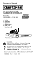
Operator's
Manual
[RAFTSMAN.°
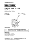
18-Inch Straight Shaft/31 cc/2-Cycle
GAS-POWERED BRUSHWACKER ®
Brushcutter/Trimmer
Model No.
316.74520
•
•
•
•
•
•
,_
manual and follow all its Safety Rules and
WARNING: Before using this product, read this
Operating Instructions.
Sears, Roebuck,
and Co., Hoffman
OPERATOR S MANUAL PART NO. 769-00066
PRINTED IN U.S.A.
Safety
Assembly
Operation
Maintenance
Parts List
Espa_ol
Save this manual for future reference.
Estates, IL 60179 USA
2/02
Revl
Warranty Statement
2
Maintenance
17
California Proposition 65 Warning
2
Service and Adjustments
19
Spark Arrestor
2
Storage
23
Rules for Safe Operation
Contents of Hardware Pack
3
Specifications
23
Assembly
7
8
Troubleshooting
EPA
Operation
12
Chart
24
26
Parts List
27
Espa_ol
E1
FULL ONE-YEAR WARRANTY ON CRAFTSMAN ® GAS-POWERED
BRUSHWACKER ® BRUSHCUTTER/'rRIMMER
For one year from the date of purchase, when this Craftsman Gas-Powered Brushwacker Brushcutter/Trimmer
is
maintained, lubricated and tuned up according to the operating and maintenance instructions in the operator's manual,
Sears will repair, free of charge, any defect in materials or workmanship.
This warranty excludes nylon line, spark plug, air filter, and expendable parts that become worn during normal use.
If this Brushwacker Brushcutter/Trimmer is used for commercial purposes, this warranty applies for 90 days from the date
of purchase. If this Brushwacker Brushcutter/Trimmer
is used for rental purposes, this warranty applies for 30 days from
the date of purchase.
This warranty applies only while this product is in use in the United States.
WARRANTY SERVICE IS AVAILABLE BY RETURNING THE BRUSHWACKER BRUSHCITTER/TRIMMER
EST SEARS SERVICE CENTER IN THE UNITED STATES.
TO THE NEAR-
This warranty gives you specific legal rights, and you may also have other rights which vary from state to state.
Sears, Roebuck and Co., D/817 WA, Hoffman Estates, IL 60179
THE ENGINE EXHAUST FROM THIS
PRODUCT CONTAINS CHEMICALS
KNOWN TO THE STATE OF CALIFORNIA
TO CAUSE CANCER, BIRTH DEFECTS
OR OTHER REPRODUCTIVE
HARM.
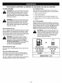
NOTE: For users on U.S. Forest Land and in the states of California, Maine, Oregon and Washington. All U.S. Forest
Land and the state of California (Public Resources Codes 4442 and 4443), Oregon and Washington require by law that
certain internal combustion engines operated on forest brush and/or grass-covered areas be equipped with a spark
arrestor, maintained in effective working order, or the engine be constructed, equipped and maintained for the prevention
of fire. Check with your state or local authorities for regulations pertaining to these requirements. Failure to follow these
requirements could subject you to liability or a fine. This unit is factory equipped with a spark arrestor. If it requires
replacement, ask your Sears Service Center to install the Accessory Part #182747 Spark Arrestor.
SPECIAL NOTE: exposure to vibrations through prolonged use of gasoline powered hand tools could cause blood vessel
or nerve damage in the fingers, hands, and joints of people prone to circulation disorders or abnormal swelling. Prolonged
use in cold weather has been linked to blood vessel damage in otherwise healthy people. If symptoms occur such as
numbness, pain, loss of strength, change in skin color or texture, or loss of feeling in the fingers, hands or joints,
discontinue use of this tool and seek medical attention. An anti-vibration system does not guarantee the avoidance of these
problems. Users who operate power tools on a continual and regular basis must monitor closely their physical condition
and the condition of this tool.
-2-
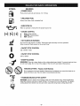
The purpose of safety symbols is to attract your
attention to possible dangers. The safety symbols, and
their explanations, deserve your careful attention and
understanding. The safety warnings do not by
themselves eliminate any danger. The instructions or
warnings they give are not substitutes for proper
accident prevention measures.
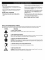
SYMBOL
MEANING
,_
DANGER: Failure to obey a safety warning
will result in serious injury to yourself or to
others. Always follow the safety precautions
to reduce the risk of fire, electric shock, and
personal injury.
WARNING: Failure to obey a safety warning
can result in injury to yourself and others.
Always follow the safety precautions to
reduce the risk of fire, electric shock, and
personal injury.
danger,
or caution. Indicates
Attention is
SAFETY warning,
ALERT SYMBOL:
required in order to avoid serious personal
injury. May be used in conjunction with other
symbols or pictographs.
_
NOTE: Advises you of information or instructions vital
to the operation or maintenance of the equipment.
IMPORTANT
READ ALL INSTRUCTIONS
BEFORE
AUTION: Failure to obey a safety warning
may result in property damage or personal
injury to yourself or to others. Always follow
the safety precautions to reduce the risk of
fire, electric shock, and personal injury.
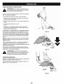
SAFETY INFORMATION
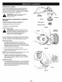
OPERATING
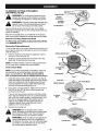
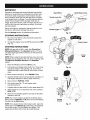
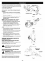
• Squeeze the throttle control and check that it returns
automatically to the idle position. Make all adjustments
or repairs before using unit.
• Read the instructions carefully. Be familiar with the
controls and proper use of the unit.
SAFETY WARNINGS
• Do not operate this unit when tired, ill, or under the
influence of alcohol, drugs, or medication.
FOR GAS UNITS
WARNING: Gasoline is highly flammable, and its vapors
can explode if ignited. Take the following precautions:
• Children and teens under the age of 15 must not use
the unit, except for teens guided by an adult.
• Store fuel only in containers specifically designed and
approved for the storage of such materials.
• All guards and safety attachments must be installed
properly before operating the unit.
• Avoid creating a source of ignition for spilled fuel. Do
not start the engine until fuel vapors dissipate.
• Inspect the unit before use. Replace damaged parts.
Check for fuel leaks. Make sure all fasteners are in
place and secure. Replace parts that are cracked,
chipped, or damaged in any way. Do not operate the
unit with loose or damaged parts.
• Always stop the engine and allow it to cool before
filling the fuel tank. Never remove the cap of the fuel
tank, or add fuel, when the engine is hot. Never
operate the unit without the fuel cap securely in place.
Loosen the fuel tank cap slowly to relieve any pressure
in the tank.
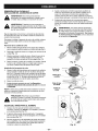
• Use only 0.095 in (2.41 mm) diameter genuine
Craftsman® replacement line. Never use metalreinforced line, wire, or rope, etc. These can break off
and become dangerous projectiles.
• Mix and add fuel in a clean, well-ventilated area
outdoors where there are no sparks or flames. Slowly
remove the fuel cap only after stopping engine and
allowing it to cool. Do not smoke while fueling or
mixing fuel. Wipe up any spilled fuel from the unit
immediately.
• Be aware of the risk of injury to the head, hands and feet.
• Clear the area to be cut before each use. Remove all
objects such as rocks, broken glass, nails, wire, or
string which can be thrown or become entangled in
the cutting attachment.
• Move the unit at least 30 ft. (9.1 m) from the fueling
source and site before starting the engine. Do not
smoke; keep sparks and open flames from the area
while adding fuel or operating the unit.
• Clear the area of children, bystanders and pets. At a
minimum keep all children, bystanders and pets outside a
50 ft. (15 m.) radius; there still may be a risk to bystanders
from thrown objects. Encourage bystanders to wear eye
protection. If you are approached, stop the engine and
cutting attachment immediately.
-3-
WHILE OPERATING
• Stop and switch the engine to OFF for maintenance,
repair, or for changing the cutting attachment or other
attachments.
• Never start or run the unit inside a closed room or
building. Breathing exhaust fumes can kill. Operate
this unit only in a well ventilated area outdoors.
• Use only genuine Craftsman® replacement parts when
servicing this unit. These parts are available from your
authorized service dealer. Do not use parts,
accessories or attachments not authorized by
Craftsman for this unit. Doing so could lead to serious
injury to the user, or damage to the unit, and void your
warranty.
• Wear safety glasses or goggles that are marked as
meeting ANSI Z87.1 standards, and ear/hearing
protection when operating this unit. Wear a face or
dust mask if the operation is dusty. Long sleeve shirts
are recommended.
• Wear heavy, long pants, boots and gloves. Do not
wear loose clothing, jewelry, short pants, sandals, or
go barefoot. Secure hair above shoulder level.
• Keep unit clean of vegetation and other materials.
They may become lodged between the cutting
attachment and shield.
• Adjust the assist handle to your size to provide the
best grip.
• To reduce fire hazard, replace faulty muffler and spark
arrestor and keep the engine and muffler free from
grass, leaves, excessive grease or carbon build up.
• Be sure the cutting attachment is not in contact with
anything before starting the unit.
WHILE
• The cutting attachment shield must always be in place
while operating the unit as a trimmer. Do not operate
unit without both trimming lines extended, and the
proper line installed. Do not extend the trimming line
beyond the length of the shield.
OPERATING
WITH
CUTTING
BLADE(S)
• Read and understand all safety warnings before
operating this unit.
• Always use the shoulder harness when using the
brush blade accessories.
• This unit has a clutch. The cutting attachment remains
stationary when the engine is idling. If it does not, have
the unit adjusted by any nonroad engine repair
establishment, individual or authorized service dealer.
• Keep the assist handle between the operator and
cutting attachment or blade at all times.
• NEVER cut with the cutting blade(s) located over 30
inches (76 cm) or more above the ground level.
• Use the unit only in daylight or good artificial light.
• Blade thrust may occur when the spinning blade
contacts an object that it does not immediately cut.
Blade thrust can be violent enough to cause the unit
and/or operator to be propelled in any direction, and
possibly lose control of the unit. Blade thrust can
occur without warning if the blade snags, stalls, or
binds. This is more likely to occur in areas where it is
difficult to see the material being cut.
• Avoid accidental starting. Be in the starting position
whenever pulling the starter rope. The operator and unit
must be in a stable position while starting. See
Stopping/Starting Instructions in the Operation section.
• Use the right tool. Only use this tool for the purpose
intended.
• Do not overreach. Always keep proper footing and
balance.
• Do not cut anything thicker than 1/2 inch with the
Craftsman 4-tooth blade, or thicker than 2 inches with
the 44-tooth saw blade, or a violent kickback could
• Always hold the unit with both hands when operating.
Keep a firm grip on both the front and rear handle or grips.
occur.
• Keep hands, face, and feet at a distance from all
moving parts. Do not touch or try to stop the cutting
attachment when it is rotating.
• Do not attempt to touch or stop the blade while it is
rotating.
• A coasting blade can cause injury while it continues to
spin after the engine is stopped or the throttle trigger
is released. Maintain proper control until the blade has
completely stopped rotating.
• Do not touch the engine or muffler. These parts get
extremely hot from operation. When turned off they
remain hot for a short time.
• Do not operate the engine faster than the speed
needed to cut, trim, or edge. Do not run the engine at
high speed when not cutting.
• Do not sharpen the cutting blade(s). Sharpening a
blade can cause the blade tip to break off while in use.
This can result in severe personal injury. Replace dull
blade(s).
• Always stop the engine when cutting is delayed or
when walking from one cutting location to another.
• Stop the engine IMMEDIATELY if you feel excessive
vibration. Vibration is a sign of trouble. Inspect
thoroughly for loose nuts, bolts, or damage before
continuing. Repair or replace affected parts as
necessary.
• If you strike or become entangled with a foreign
object, stop the engine immediately and check for
damage. Do not operate before repairing damage. Do
not operate the unit with loose or damaged parts. Do
not operate unit with a bent, cracked, or dull blade.
Discard blades that are bent, warped, cracked or
broken.
-4-
AFTER USE
Allow the engine to cool before storing or transporting.
Be sure to secure the unit while transporting.
• Clean cutting blade(s) with a household cleaner to
remove any gum buildup. Oil the blade(s) with machine
oil to prevent rust.
Store the unit in a locked up and dry, or high and dry
place to prevent unauthorized use or damage. Keep
out of the reach of children.
• Lock up and store the cutting blade in an appropriate
area to protect the blade from unauthorized use or
damage.
OTHER
Never douse or squirt the unit with water or any other
liquid. Keep handles dry, clean and free from debris.
Clean after each use. See the Maintenance and
Storage sections.
SAFETY WARNINGS
• Never store the unit, with fuel in the tank, inside a
building where fumes may reach an open flame or
spark.
Keep these instructions. Refer to them often and use
them to instruct other users. If you loan someone this
unit, also loan them these instructions.
SAVE THESE INSTRUCTIONS
SAFETY AND INTERNATIONAL
SYMBOLS
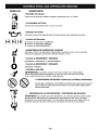
This operator's manual describes safety and international symbols and pictographs that may appear on this 3roduct.
Read the operator's manual for complete safety, assembly, operating and maintenance and repair information.
SYMBOL
MEANING
• SAFETY
ALERT
SYMBOL
ndicates danger, warning, or caution. May be used with other symbols.
Failure to follow operating instructions and safety precautions in operator s manual can result in
•serious
READ injury.
OPERATOR'S
MANUAL
Read operator's
manual before starting or operating this unit.
O
• WEAR
EYE AND HEARING
PROTECTION
WARNING: Thrown objects and loud noise can cause severe eye injury and hearing loss. Wear
eye protection meeting ANSI Z87.1-1989 standards and ear protection when operating this unit.
Use a full face shield when needec
• THROWN
/
//-_
OBJECTS
CAN CAUSE
SEVERE
Do not operate unit without proper attachments
• KEEP CHILDREN
INJURY
and guards in place.
AWAY
WARNING: Keep all bystanders, especially children and pets. at least 50 feet (15 m.) from the
operating area. Stop unit immediately if you are approachec
-5-
SYMBOL
MEANING
• PRIMER
BULB
Push primer bulb fully and slowly, 5 to 7 times.
• UNLEADED
FUEL
Always use clean, fresh unleaded fuel.
• INDICATES
OIL
Refer to operator's manual for the proper type of oil.
A
B
C
• CHOKE
B
C
CONTROL
PARTIAL choke position.
RUN position.
• HOT SURFACE
WARNING
Do not touch the engine or muffler. These parts get extremely hot from operation.
When turned off they remain hot for a short time.
• ON/OFF
STOP CONTROL
ON / START / RUN
• ON/OFF
STOP CONTROL
OFF or STOP
• SHARP
BLADE(S)
WARNING: There is a sharp blade on the cutting attachment shield. To prevent serious injury,
do not touch edge. Do not touch the edges of the 44-tooth saw blade. Wear gloves.
• BRUSHCUTTERS
- Replace
Dull Blade(s)
Do not sharpen the brush blade(s). Sharpening the blade(s) can cause the blade tip to
break off while in use; this can result in severe personal injury.
• TRIMMER/BRUSHCUTTER
SAFETY
WARNING: Thrown objects and rotating cutter can cause severe injury. Keep bystanders,
especially children and pets, at least 50 feet (15 m) away from the cutting area. The plastic
cutting attachment shield must be used when using the string head cutting attachment.
-6-
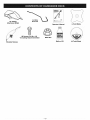
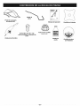
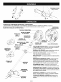
18" Cutting
Attachment Shield
Locking
Rod Tool
Operator's Manual
(3) Screws (1/4-20 x 1/2)
- for Cutting Attachment Shield
4-Tooth Blade
Blade Nut
Bottle of Oil
Shoulder Harness
-7-
44-Tooth
Blade
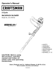
Your unit can be assembled in three (3) configurations:
]1
CUTTING ATTACHMENT
and light weeds.
-- used for cutting grass
4-TOOTH BLADE -- used for cutting grass, weeds.
and woody brush up to 1/2 inch in diameter.
I
i iiii ii i i_iiii iii!I_
u
44-TOOTH BLADE -- used for cutting grass, weeds,
and woody brush up to 2 inches in diameter.
CARTON
CONTENTS
ASSEMBLY
• Brushcutter/Trimmer
INFORMATION
To ensure safe and proper operation of your unit, all
parts and hardware you assemble must be tightened
securely.
• Assist Handle with upper and middle clamps attached
• Hardware Pack
-8-
TOOLS
REQUIRED
• 5/8 inch Closed-Ended
FOR ASSEMBLY
Remove the cutting attachment shield from the shield
mount by removing the three (3) screws with an
appropriate screwdriver (Fig. 4). Store parts for future use.
Wrench (if installing blade)
• Flat Blade Screwdriver
• Large Phillips Screwdriver
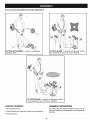
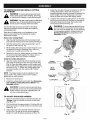
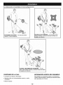
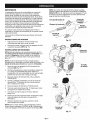
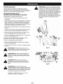
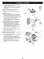
INSTALLING
HANDLE
AND ADJUSTING
Assist Handle
THE ASSIST
(4)
Installing
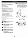
1. Remove the screws and nuts, and the top and middle
clamp pieces that were installed on the assist handle
for shipping.
2.
3.
Top Clamp
Middle Clamp
Place the assist handle between the top and middle
clamp pieces (Fig. 1).
Bottom Clamp
Nuts -_
While holding the three pieces together, install the four
(4) screws through the top clamp and into middle clamp.
_®
Fig, 1
NOTE: The holes in the top and middle clamps will line up
only when assembled correctly.
4.
Place the clamps and assist handle the over the shaft
housing and onto the bottom clamp.
5.
Hold each hex nut in the bottom clamp recess with a
finger. Start screws with a large Phillips screwdriver.
Do not tighten until you make the handle adjustment.
Adjusting
6. Loosen the screws so that the assist handle can be
easily moved in the clamp assembly. Do not remove
the screws or nuts.
7.
Slide the assist handle in or out until the arrow/white
line on the decal touches the clamp assembly (Fig. 2).
8.
While holding the unit in the operating position (Fig. 3),
position the assist handle to the location that provides
you the best grip.
9.
Tighten the clamp screws evenly, until the assist handle
is secure.
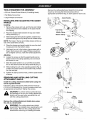
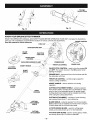
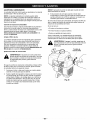
REMOVING AND INSTALLING
ATTACHMENT
SHIELD
Fig. 2
CUTTING
Install the cutting attachment shield when using the
unit as a grass trimmer.
Install the cutting attachment shield with the three (3)
(1/4-20 x 0.50) screws (Fig. 4) onto the blade shield with
an appropriate screwdriver. Tighten the screws.
Fig, 3
CAUTION: To prevent serious personal injury
and damage to the unit, the cutting attachment
shield must be used when operating this unit
with the cutting attachment.
Gear
Housing
Blade
Shield
Remove the cutting attachment shield when using
the unit as a brushcutter.
WARNING: The cutting attachment shield
should NOT be installed when operating the unit
with a blade. Remove the cutting attachment
shield before removing or installing the blade.
Cutting
Attachment
Shield
Fig. 4
-9-
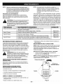
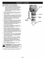
TO REMOVE CUTTING
AND INSTALL BLADE
A
,_
_!_
WARNING:
F.=.=.=.=.=.=-=-=-_
ATTACHMENT
Output Shaft
TO avoid serious personal injuryl
Output
always wear gloves while handling, removing,
or installing the blade(s) or cutting attachment.
_
Shaft Hole
Locking
WARNING: The gear housing gets hot after long
periods of use. TO avoid serious personal injury,
do not touch the housing until it has cooled.
/__--___)/
_
Rod Slot
Locking Rod _
J_
__.
V
Use the following instructions and refer to the safety
warnings to properly remove the cutting attachment and
install the blade(s).
Fig. 5
Place the unit upside down, on a workbench or the ground,
when removing and installing the cutting attachment or blade.
Remove the Cutting Attachment Shield
See Removing and Installing Cutting Attachment Shield
in the Assembly section.
Remove the Cutting Attachment
1. Line up the hole in the output shaft with the locking rod
slot. Insert the locking rod through the slot into the output
shaft hole (Fig. 5).
2. Hold the locking rod in place by grasping it next to
the boom of the unit (Fig. 6).
3.
Fig. 6
Cutting Attachment
Screw the cutting attachment clockwise off of the
shaft (Fig. 7) and store for future use.
NOTE: The blade retainer under the cutting attachment
will be used when installing the brush blade(s).
Install a Brush Blade
Locking Rod
Slot
NOTE: The 4-tooth brush blade is reversible, which can
be reversed by removing the blade, turning it upside
down, and reinstalling it. The 44-tooth saw blade is
NOT reversible and should be installed only as shown!
Locking Rod
Fig. 7
Install the blade, blade retainer and lock nut (Fig. 8).
Insert the locking rod through the slot into the outout
shaft hole. Make sure that the blade stays flat and
centered against the output shaft while tightening
the lock nut counterclockwise (Fig. 9).
4.
5.
Lock Nut
44-Tooth
If you have a torque wrench tighten the lock nut to
325-335 in..Ibs (37-38 N.m), while holding the
locking rod in the slot.
Blade Shield
J
If you do not have a torque wrench, hold the locking
rod in the slot. Rotate the lock nut counterclockwise
with a 5/8 inch closed-ended or socket wrench, until
the lock nut presses against the washer and the
blade is snug. Make sure the blade assembly is
installed correctly, then rotate the lock nut an
additional 1/4-1/2 turn (Fig. 9).
6.
A
Blade
Locking
Rod
Fig. 8
Remove the locking rod.
WARNING: Do not sharpen either cutting
blade. Sharpening the blades can cause a blade
tip to break off while in use. This can result in
severe personal injury to yourself or others.
output
shaft after
nut isis flat
tightened.
WARNING:
Verifythe
thelock
blade
against If
the
the blade is off-center, the unit will be damaged
by vibration, and the blade may fly off. which
can cause serious personal injury.
!/4-1/2
Turn
Fig. 9
-10-
TO REMOVE BLADE AND INSTALL
ATTACHMENT
jl_
A"
CUTTING
Adjust the shoulder harness for balance so that the
cutting attachment is level with the ground. A
properly adjusted shoulder harness will support the
entire weight of the unit, freeing your arms and
hands to guide and control the cutting motion.
4.
WARNING: To avoid serious personal injury,
always wear gloves while handling, removing,
or installing the blade(s) or cutting attachment.
.
A
WARNING: The gear housing gets hot after long
periods of use. To avoid serious personal injury,
do not touch the housing until it has cooled.
WARNING: To avoid serious personal injury,
do not connect the shoulder harness strap to
the unit until it is started and you are standing
in the operating position. Always follow the
Starting Instructions as described in the
Operation section.
Use the following instructions and refer to the safety
warnings to properly remove the blade and install the
cutting attachment.
Place the unit upside down, on a workbench or the
ground, when removing and installing the cutting
attachment or blade.
Remove the Cutting Blade
1. Align the shaft bushing hole with the locking rod slot
and insert the locking rod into the bushing hole (Fig. 5).
2.
Hold the locking rod in place by grasping it next to
the boom of the unit (Fig. 10).
3.
While holding the locking rod, loosen the lock nut on
the blade by turning it clockwise with a 5/8 inch
closed-end or socket wrench (Fig. 10).
4.
Remove the lock nut, blade retainer and blade. Store
the lock nut and blade together for future use in a
secure place. Store out of reach of children.
Loosen
Fig. 10
Install the Cutting Attachment
5. Align the output shaft hole with the locking rod slot
and insert the locking rod into the output shaft hole.
(Fig. 5). Place the blade retainer on the output shaft
with the flat surface against the output shaft bushing
as shown in Fig. 11. Screw the cutting attachment
counterclockwise onto the output shaft. Tighten
securely.
Cutting
Attachment
Blade
Retainer
NOTE: The blade retainer must be installed on the
output shaft in the position shown for the cutting
attachment to work correctly.
6.
Remove the locking rod.
7.
Install the cutting attachment shield. See Removing
and Installing Cutting Attachment Shield in the
Assembly section.
Lengthen the harness by pulling down on the strap
and moving the buckle up. Shorten the harness by
pulling the strap back through the buckle while
moving the buckle down (Fig. 13)
Output Shaft
Bushing
Locking Rod
--
Fig. 11
CAUTION: To prevent serious personal injury
and damage to the unit, the cutting attachment
shield must be used when operating this unit
with the cutting attachment.
TO ADJUST
SHOULDER
HARNESS
1. Place the shoulder harness on the left shoulder, the
"Danger" sign on the back, and hook on the right
thigh (Fig. 12).
2.
The hook should be approximately 15 inches (38 cm)
above your knee, or six (6) inches (15 cm) below your
waist (Fig. 12).
3.
Attach the hook to the shoulder harness clamp on
the unit (Fig. 14) and lift the unit to the operating
position to verify fit before operating unit (Fig. 12).
Fig. 12
-11 -
_
Fig. 14
Fig. 13
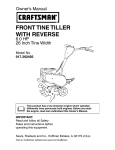
KNOW YOUR
Harness
Shoulder
Clamp
BRUSHCUTrER/TRIMMER
READ THIS OPERATOR'S MANUAL AND SAFETY RULES BEFORE OPERATING YOUR UNIT. Compare the illustrations
with your unit to familiarize yourself with the location of various controls and adjustments.
CHOKE CONTROL
Save this manual for future reference.
FUEL CAP
STARTER ROPE GRIP ____
BLADE
SHIELD
THROTTLE
___
LOCK-OUT\
ON/OFF STOP
\\
CONTROL
PRIMER BULB
_,/
44-TOOTH
SAW BLADE
SHOULDER
HARN_
THROTTLE
ASSIST HANDLE
SPARK PLUG
ON/OFF STOP CONTROL - used to turn the engine ON
and OFF. The switch must be in the ON position when
starting the engine.
BLADE
SHIELD
J
CONTROL
J
PRIMER BULB - removes air from the fuellines and fills
the carburetor with fuel.
THROTTLE CONTROL - controls engine speed for
various cutting conditions.
ASSIST HANDLE - used to hold the unit during
operation.
4-TOOTH
BLADE
CUTTING ATTACHMENT SHIELD - protects operator
from thrown debris. Contains line cut-off blade to make
sure the line is not extended beyond its proper length.
Cutting attachment shield must be installed at all times
when using the cutting attachment.
SHAFT
HOUSING
CUTTING ATTACHMENT - consists of a reel housing,
reel, spring, Bump Knob TM and cutting line.
CUTTING
_ATTACHMENT
SHIELD
BLADE SHIELD - protects operator from thrown debris.
Blade shield must be installed at all times when using the
4-tooth blade and the 44-tooth saw blade.
4-TOOTH BRUSH BLADE - used for cutting grass,
weeds, and woody brush up to 1/2 inch diameter.
CUTTING
ATTACHMENT
44-TOOTH SAW BLADE -used for cutting grass, weeds,
and woody brush up to 2 inches in diameter.
-12-
THIS ENGINE
IS CERTIFIED
TO OPERATE
ON UNLEADED
Use of Blended Fuels
TO FUEL ENGINE
If you choose to use a blended fuel, or if its use is unavoidable, the following precautions are recommended.
CAUTION: Be sure to read these instructions
carefully before attempting to start or operate
this unit. Using old or improper oil or fuel. or
improperly mixing the oil and fuel. can cause
engine damage. This type of damage will VOID
the engine warranty.
1. Always use fresh fuel mix.
2.
Drain the tank and run the engine dry before storing
the unit.
WARNING: Gasoline is extremely flammable
and its vapors can explode if they are ignited.
Always stop the engine and allow it to cool
before filling the fuel tank. Do not smoke while
filling the tank. Keep sparks and open flames
away from the area.
Use of Fuel Stabilizer
If using a brand of oil other than Craftsman, use of fuel
stabilizer will inhibit corrosion and minimize the formation
of gum deposit. Add 0.8 oz. (23 ml) of stabilizer per gallon
of fuel per instructions on container. NEVER add fuel
stabilizer directly to the unit's fuel tank. Using a fuel
stabilizer can keep fuel fresh for up to six (6) months.
Oil Type
A 3.2 oz. (95ml) bottle of Craftsman® engine oil. containing fuel stabilizer, is included with your product. Craftsman brand oil is recommended for this outdoor power
tool. If another brand is usea. make sure it is high quality
oil, formulated for 2-cycle. air-cooled engines.
,_
DANGER: Combustible mixture contains
petroleum distillate. Store away from heat or
open flame. Harmful or fatal if swallowed. If
swallowed, do not induce vomiting. CALL
PHYSICIAN IMMEDIATELY. Avoid prolonged
contact with skin. Wash thoroughly after
handling. Do not reuse bottle,
Recommended
Use a special additive.
3. Always agitate the fuel mix before fueling the unit,
4.
Recommended
GAS AND OIL MIXTURE,
Fuel Type
maximum reliability,
payengine
strict attention
the
CAUTION:
For proper
operation toand
oil and fuel mixing instructions on the 2-cycle
oil Container. Use a40:1 fuel/oil ratio. Use 2cycle oil. Using improperly mixed fuel can
severely damage the engine.
UNLEADED GAS
Use clean, fresh, unleaded gasoline that is less than 60
days old.
1 US, GALLON
SEARS 2 CYCLE OIL
+
(3,8 LITERS)
Oil and Fuel Mixing Instructions
Thoroughly mix the proper ratio of unleaded gasoline
with 2-cycle engine oil in a separate fuel can. 40:1. Do
not mix them directly in the engine fuel tank.
1 LITER
MIXING
Use 3.2 oz. (95ml) of 2-cycle engine oil per one gallon of
unleaded gasoline to achieve a 40:1 fuel/oil ratio.
-13-
3,2 FL, OZ,
(95 ml)
+
25 ml
RATIO - 40:1
IMPORTANT
Experience indicates that alcohol blended fuels (called
gasohol or using ethanol or methanol) can attract moisture which leads to separation and formation of acids
during storage. Acidic gas can damage the fuel system
of an engine while in storage. To avoid engine problems,
empty the fuel system before storage of 30 days or
longer. Drain the fuel tank, start the engine and let it run
until the fuel lines and carburetor are empty. Use fresh
fuel next season.
Start/OFF (I)
On/Off Stop Control
Throttle Lock-Out
- Stop/OFF (O)
\
Never use engine or carburetor cleaner products in the
fuel tank or permanent damage may occur.
See the Storage section for additional information.
STOPPING
Fig, 15
INSTRUCTIONS
1. Run the unit at idle for a few moments to allow the
engine to cool down.
2.
To stop the engine move On/Off Stop Control to OFF
(Fig. 15).
STARTING
_ke
INSTRUCTIONS
NOTE: Mix gas with oil (40:1 ratio). See Oil and Fuel
Mixing Instructions in the Operation section. Fill your
unit with oil and gas mixture and set it on the ground to
start (Fig. 17).
_
NOTE: When using the shoulder harness, have it on and
adjusted, but not clipped to the unit, prior to starting. See
To Adjust the Shoulder Harness in the Assembly
section..
1. Move On/Off Stop Control to ON (Fig. 16).
2.
Control
Fully press and release primer bulb 5 to 7 times. Fuel
should be visible in the bulb (Fig. 16). If fuel hasn't
entered the bulb, press three (3) more times or until it
does.
Fig. 16
3. Move choke control (Fig. 16) to CHOKE (H A).
4.
Squeeze throttle control and pull starter rope (Fig. 17)
until engine attempts to start (5 pulls maximum).
5.
Move choke to PARTIAL (1_1B).
6.
Pull starter rope (Fig. 17) until engine starts
(3 pulls maximum).
7.
If engine does not start within 3 pulls, repeat steps 2-6.
8.
Allow engine to run 10 seconds, then move choke to
RUN (1÷1C).
9.
Stand in the operating position and clip the shoulder
harness to the unit.
Starter
Rope
I
NOTE: For a warm engine, go directly to Step 5 above.
Move choke to PARTIAL (1_1B). Be sure the On/Off Stop
Control is in the ON position.
Throttle
/
Control
NOTE: If the engine floods while trying to start, place the
choke lever in the RUN (C)I÷1 position (Fig. 16). Squeeze
the throttle control. Pull the starter rope briskly. The
engine should start within three (3) to eight (8) pulls.
Fig. 17
- 14-
Primer
Bulb
HOLDING
_
THE TRIMMER
hearing,
and
body
protection
to
reduce
the
risk offoot
injury
WARNING: Always wear eye,
when operating this unit.
Before operating the unit, stand in the operating position
(Fig. 18). Check for the following:
• The operator is wearing eye protection and Proper
clothing.
• The right arm is slightly bent, and the hand iS holding
the shaft grip.
• The left arm is straight, and the hand is holding the
handle.
• The unit is below waist level.
• The cutting attachment is parallel to the ground and
easily contacts the vegetation to be cut without the
operator having to bend over.
TO ADJUST
THE TRIMMING
Fig. 18
LINE LENGTH
Your trimmer is equipped with a cutting attachment that
allows the operator to release more trimming line without
stopping the engine. To release additional line, lightly
bump the cutting attachment on the ground while
operating the trimmer at high speed (Fig, !9)-
%
NOTE: Line release becomes more difficult as cutting
line becomes shorter. Always keep the trimming line
extended to its full cutting length.
Each time the head is bumped, about 1 inch (25.4 mm)
of line is released. A blade in the guard will cut the line to
the proper length if excess line is released.
For best results, bump the head on bare ground or hard
soil. If line release is attempted in tall grass, the engine
may stall.
,_
,_
WARNING:
Fig. 19
Do not remove or alter the line
Cutting blade assembly. Excessive line length
can cause the clutch to overheat and result in
serious personal injury.
DECORATIVE
TRIMMING
Perform decorative trimming by removing all vegetation
around trees, posts, fences, etc.
Rotate the entire unit so that the cutting attachment
a 30° angle to the ground (Fig. 20).
is at
Fig. 20
-15-
PROPER
STANCE
WARNING:
Blade thrust may occur when the
spinning blade contacts an object that it does
not immediately cut. Blade thrust can be
violent enough to cause the unit and/or
operator to be propelled in any direction, and
possibly lose control of the unit. Blade thrust
can occur without warning if the blade snags,
stalls or binds. This is more likely to occur in
areas where it is difficult to see the material
being cut.
When operating the unit, maintain proper footing and
balance. Hold the unit with both hands (Fig. 21). Do not
overreach. Keep all parts of your body away from the
cutting attachment.
BLADE
OPERATING
TIPS
To establish a rhythmic cutting procedure:
• Plant feet firmly, comfortably
apart.
• Bring the engine to full throttle before entering the
material to be cut. The blade has maximum cutting
power at full throttle and is less likely to bind, stall, or
cause blade thrust, which can result in serious injury to
the operator or others.
• Cut while swinging the upper part of your body from
right to left.
• Always release the throttle trigger and allow the engine
to return to idle speed when not cutting.
• Swing the unit in the same direction as the blade
spins, increasing the cutting action.
• Move forward to the next area to be cut after the
return swing and plant feet again.
To reduce the chance of material wrapping around the
blade, follow these steps:
• Cut at full throttle.
• Swing the unit into material to be cut from your right to
your left (Fig. 22).
• When making the return swing avoid the material you
just cut.
Fig. 21
_lb
and
body protection
reduce
risk offoot
injury
WARNING:
Always to
wear
eye, the
hearing,
when operating this unit.
WARNING: Do not sharpen the brush
blade(s). Sharpening a blade can cause the
blade tip to break off while in use. This can result in severe personal injury.
Fig. 22
,_
never
operate To
thisavoid
unit serious
as an edger
whileinjury,
using
WARNING:
personal
the cutting blade.
WARNING: To avoid serious personal injury,
turn off engine and allow blade to stop before
removing materials wrapped around the blade
shaft. The coasting blade can seriously cut you
if accidentally touched.
Do not clear away cut material with the engine
running or the blade turning.
-16-
MAINTENANCE
SCHEDULE
NOTE: Maintenance, replacement, or repair of the emission
control devices and system may be performed by
any nonroad engine repair establishment, individual
or authorized service dealer.
These required maintenance procedures should be
performed at the frequency stated in the table. They
should also be included as part of any seasonal tune-up.
NOTE: Some maintenance procedures may require
special tools or skills. If you are unsure about
these procedures take your unit to any nonroad
engine repair establishment, individual or
authorized service dealer.
I
'_
WARNING: To prevent serious injury, never do I
k
maintenance
or repairs with
running.
Always do maintenance
and unit
repairs
on a cool
unit. Disconnect spark plug wire to ensure the
unit will not start.
I
In order to assure peak performance of your engine,
inspection of the engine exhaust port may be necessary
after 50 hours of operation, if you notice lost RPM, poor
performance or general lack of acceleration, this service
may be required. If you feel your engine is need of this
inspection, refer service to any nonroad engine repair
establishment, individual or authorized service dealer for
repair. DO NOT attempt to perform this process yourself
as engine damage may result from contaminants
involved in the cleaning process for the port.
FREQUENCY
MAINTENANCE
Before Starting Engine
Check for loose or damaged parts.
Fill fuel tank with correct oil and fuel mixture.
Page 13
Every 10 Hours
Clean and re-oil air filter.
Page 17
Every 25 Hours
Check spark arrestor and clean.
Check spark plug condition and gap.
Page 22
Page 18
Every 50 Hours
Inspect exhaust port and spark arrestor screen for clogging
or obstruction to assure maximum performance levels.
Page 22
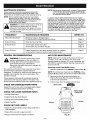
GENERAL
REQUIRED
RECOMMENDATIONS
NOTE: Clean and re-oil the air filter every 10 hours of
operation. Your unit's air filter is one of the most
important areas to maintain. If it is not maintained, you
will VOID the warranty. Before cleaning, make sure the
unit is turned off.
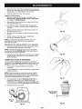
Removing the Air Filter/Muffler
DAMAGED/WORN
Cover
1. Place the choke lever in the PARTIAL choke position (B).
NOTE: The choke lever must be in the PARTIAL choke
position (B) (Fig. 23) to remove the air -'liter/muffler cover.
These required maintenance procedures should be
performed at the frequency stated in the table. They
should also be included as part of any seasonal tune-up.
FOR
TO:
AIR FILTER MAINTENANCE
WARNING: To prevent serious injury, never
perform maintenance on the unit while it is
running. Shut off the unit and allow it to cool
down before doing any maintenance.
Disconnect the spark plug wire to prevent the
Unit from starting.
The warranty on this line trimmer does not cover items
that have been subjected to operator abuse or
negligence. To receive full value from the warranty, the
operator must maintain the unit as instructed in this
operator's manua!.
CHECK
REFER
PARTS
2.
Remove the four (4) screws securing the air
filter/muffler cover (Fig. 23). Use a flat blade or
T-20 Torx bit screwdriver.
3.
Pull the cover from the engine. Do not force.
Choke Lever
Inspect the unit for any worn or damaged parts. Repair
or replace damaged parts before operating.
CHECK
FOR LOOSE FASTENER
PARTS
O
Partial Choke
Position (B]
• Cutting Attachment
• Assist Handle Hex Nuts/Screws
• Cutting Attachment Shield Screws
Screws
• Spark Plug Wire
CLEAN
_0_0_
UNIT AND LABELS
• Clean the unit and label s using a damp cloth with a
mild detergent.
• Wipe off the unit with a clean dry cloth.
• Keep air vents free from debris at all times.
Fig. 23
-17-
Screws
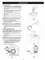
Cleaning the Air Filter
f
1. Remove air filter/muffler cover. See Removing the
Air filter/Muffler Cover in the Maintenance section.
2.
Remove the air filter from behind the air filter/muffler
cover (Fig. 24).
3.
Wash the filter in detergent and water (Fig. 25). Rinse
the filter thoroughly. Squeeze out excess water.
Allow it to dry Completely.
Apply enough clean SAE 30 oil to lightly Coat the
filter (Fig. 26).
4.
5.
Squeeze the filter to spread and remove excess oil
(Fig. 27),
6.
Replace the air filter in the air filter/muffler cover (Fig. 24).
NOTE: Operating the unit without the air filter and air
filter/muffler cover assembly wi!! VOID the warranty.
J
f
/
Fig, 25
Reinstalling the Air filter/Muff!er Cover
1. Place the air filter/muffler cover over the back of the
carburetor and muffler.
NOTE: The choke lever must be in the PARTIAL choke
position (B) (Eig. 23) to install the air filter!muffler cover.
2.
J
Insert the four (4) screws into the holes in the air
filter/muffler cover (Fig. 23) and tighten. Do not over
TO REPLACE
SPARK PLUG
Use a Champion RDJ7Y spark plug (or equivalent). Correct
air gap is 0.020 in. (0.50 ram). Remove plug after every 25
hours of operation and check its condition (Fig_28).
Fig, 26
1. Stop the engine and pull the spark plug wire off of
the spark plug.
2.
Clean around the spark plug and remove it from the
cylinder head.
/
/
NOTE: Replace a cracked, fouled, or dirty spark plug. Do
not sand blast, scrape, or clean electrodes because the
engine could be damaged by grit entering the cylinder.
3.
Set the air gap at 0.020 in. (0.50 mm) using a wire
feeler gauge (Fig. 28). Install a correctly gapped
spark plug into the cylinder head. Torque to
110.120 in.lb (12.3-1&5 N-m).
4.
Replace the spark plug wire.
/
Fig. 27
=
0.020 inch
(0.50 mm)
A
Fig. 28
-18-
TO CLEAN
\
UNIT
Do not use any strong detergents on the plastic housing
or the handle. They can be damaged by certain
household cleaners that contain aromatic oils such as
pine and lemon, and by solvents such as kerosene.
Wipe off any moisture with a soft cloth.
Reel
Housing
before
servicing
cutting
attachment.
WARNING:
To the
prevent
injury,
turn the unit off
Spring
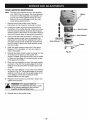
LINE INSTALLATION
FOR THE
CUTTING ATTACHMENT
Reel
The trimming line in the cutting attachment may be
replaced by two different methods:
Captured
Bolt
Bump Knob
• Winding the reel with new line, or
TM
• Installing a prewound reel
Fig. 29
The Correct Line to Use
\
WARNING: Always use Craftsman® trimmer
replacement line. To avoid injury, never use
metal-reinforced line, wire, or rope, etc..These
can break off and become a dangerous
projectile.
Reel
Reel
Housing
\
\
It is very important to use the correct size line. Use line
with a diameter of 0.095 inch (2.41 mm). The engine may
overheat and fail if you use a size other than specified.
Removing the Reel
1. Hold the reel housing with one hand and unscrew
the Bump Knob TM clockwise (Fig. 29). Inspect the
captured bolt inside the Bump Knob to make sure it
moves freely. Replace the Bump Knob if it is
damaged.
2.
Remove the inner reel and spring (Fig. 29).
3.
Use a clean cloth to clean the inner surface of the
reel housing (Fig. 39).
Spring
Fig. 30
NOTE: Always clean the reel, reel housing, and shaft
before reassembling the cutting head.
4.
\
\
Check the indexing teeth on the reel and reel
housing for wear. If necessary, remove any burrs or
replace the reel or reel housing (Fig. 39).
Winding the Reel
1. Take approximately 40 feet (12.2 m) of new trimming
line. Loop it into two equal lengths. Insert each end
of the line through one of the two holes in the reel.
Pull the ends through equally until the loop is as
small as possible (Fig. 31).
\
\
Loop
Fig. 31
-19-
2.
Place your index finger between the two lines to stop
the lines from overlapping (see Fig. 32).
3.
Wind both lines at the same time in even and tight
layers onto the reel, in the direction indicated on the
reel (Fig. 32).
NOTE: Failure to wind the lines in the direction indicated
will cause the cutting head to operate incorrectly.
4.
insert one line end into each holding slot (Fig. 33).
Reinstalling the Reel
Reel F--
1. insert one line end through each of the eyelets in the
reel housing, and insert the reel and spring back into
the reel housing (Fig. 34).
2.
Grasp the line ends and pull firmly to release them
from the holding slots in the reel.
3.
Hold the reel in place and screw the Bump Knob TM
counterclockwise back onto the reel (see Fig. 29).
TO INSTALL
A PREWOUND
Fig. 32
REEL
Holding
Slots
1. Hold the reel housing with one hand and unscrew
the Bump Knob clockwise (Fig. 29). Inspect the bolt
inside the Bump Knob to make sure it moves freely.
Replace the Bump Knob if damaged.
2.
Remove the old reel from the reel housing (Fig. 29).
3.
Remove the spring from the old reel (Fig. 29).
4.
Use a clean cloth to clean the inner surface of the
reel housing (Fig. 39).
5.
Place the spring in the new reel.
Fig. 33
NOTE: The spring must be assembled on the reel before
reassembling the cutting attachment.
6.
7.
8.
Reel
Housing
/
/
i
//
insert the ends of the line through the eyelets in the
reel housing (Fig. 34).
/
Place the new reel inside the reel housing. Push the
reel and reel housing together. While holding the reel
and reel housing, grasp the ends and pull firmly to
release the line from the holding slots in the reel.
/
Hold the reel in place and install the Bump Knob by
turning counterclockwise. Tighten securely.
Fig. 34
- 20 -
/
/
/
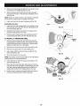
CARBURETOR
ADJUSTMENT
NOTE: The cutting attachment should not rotate when
the engine idles.
The idle speed of the engine is adjustable though the air
filter/muffler cover (Fig 35).
3.
NOTE: Careless adjustments can seriously damage your
unit. Any nonroad engine repair establishment, individual
or authorized service dealer should make carburetor
adjustments.
If the cutting attachment rotates when the engine
idles, turn the idle speed screw counterclockwise 1/8
of a turn at a time (as needed), to reduce idle speed.
Checking the fuel mixture, cleaning the air filter and
adjusting the idle speed screw should solve most engine
problems.
Check Fuel Mixture
If not and:
Old and/or improperly mixed fuel is usually the reason for
the unit not running properly. Drain and refill the tank with
fresh, properly mixed fuel prior to making any adjustments.
Refer to the Oil and Fuel Mixing Instructions in the
Operation section.
• The engine will not idle,
• The engine hesitates or stalls on acceleration,
• There is a loss of engine power,
have the carburetor adjusted by any nonroad engine
repair establishment, individual or authorized service
dealer.
Clean Air Filter
The condition of the air filter is important to the operation
of the unit. A dirty air filter will restrict air flow and
change the air/fuel mixture. This is often mistaken for an
out of adjustment carburetor. Check the condition of the
air filter before adjusting the idle speed screw. Refer to
Air Filter Maintenance in the Maintenance section.
WARNING When the unit is turned off make
sure the cutting attachment has stopped before
setting the unit down to prevent serious
personal injury.
Adjust Idle Speed Screw
WARNING The cutting attachment may be
spinning during idle speed adjustment. Wear
protective clothing and observe all safety
instructions to prevent serious personal injury.
Idle Speed Screw
If after checking the fuel mixture and cleaning the air
filter the engine still will not idle, adjust the idle speed
screw as follows.
1. Start the engine and let it run at a high idle for a
minute to warm up.
2.
Release the throttle trigger and let the engine idle. If
the engine stops, insert a small phillips or flat blade
screwdriver into the hole in the air filter/muffler cover
(Fig. 35). Turn the idle speed screw in, clockwise, 1/8
of a turn at a time (as needed) until the engine idles
smoothly.
Fig. 35
- 21 -
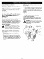
SPARK ARRESTOR
Note:
1.
2.
3.
4.
5.
6.
7.
8.
MAINTENANCE
The flow of the exhaust can be in one direction
only: AWAY from the engine. Pay close attention
to how the muffler assembly is put together, so
you can put it back together exactly as it was.
Failure to do so will damage the unit and may
cause serious personal injury.
!
!
!
!
Remove the air filter/muffler cover. See the
instructions in this manual for removing the cover.
Locate the muffler, and find the two (2) screws on
the bottom of the muffler (Fig. 36). These two screws
hold the exhaust deflector assembly and the spark
arrestor screen to the bottom of the muffler. Remove
the two (2) screws using an appropriate screwdriver.
Using a small flat blade screwdriver, carefully pry up
the spark arrestor screen from the recessed hole.
taking care to notice that the "bubbled out" part of
the spark arrestor screen is over the recessed hole.
and not inside it. Remove the spark arrestor screen
from the muffler.
Outer Deflector
Screws
Fig. 36
Reinstall the spark arrestor screen by laying it on top
of the hole on the bottom of the muffler. The
screen's "bubble" goes over the hole. and not inside
it. Make sure the edges of the spark arrestor screen
fit flat against the muffler.
Place the inner deflector on top of the spark arrestor
as shown in Fig. 36. The beveled edges of the inner
deflector must be away from the engine-side of the
muffler.
Place the outer aeflector on top of the inner deflector
as shown in Fig. 36. The beveled edges of the outer
deflector must line up with the beveled edges of the
inner deflector. Verify that the exhaust will be
directed AWAY from the engine.
Replace the two screws you removed in Step 2 and
tighten them securely.
deflector
securely, it could
the unit and
injury.
Spark Arrestor
ENGINE
Clean the spark arrestor screen with a wire brush.
Replace it if it is damaged, or if you are unable to
clean it thoroughly.
WARNING: If the exhaust
assembly is not tightened
fall off causing damage to
possible serious personal
9.
Muffler
1
I
I
Reinstall the air filter/muffler cover.
- 22 -
It is important to prevent gum deposits from forming in
essential fuel system parts such as the carburetor, fuel
filter, fuel hose or tank during storage. Also, experience
indicates that alcohol blended fuels (called gasohol or
using ethanol or methanol) can attract moisture which
leads to separation and formation of acids during
storage. Acidic gas can damage the fuel system of an
engine during storage.
Fuel stabilizer is an acceptable alternative in
minimizing the formation of fuel gum deposits
during storage. Add stabilizer to the gasoline in
fuel storage container. Follow the mix instructions
found on stabilizer container. Run engine at least
five (5) minutes after adding stabilizer.
Craftsman® 40:1, 2-cycle engine oil is already blended
with fuel stabilizer, if you do not use this Craftsman oil,
you can add a fuel stabilizer to your fuel. NEVER add
fuel stabilizer directly to the unit's fuel tank.
To avoid engine problems, the fuel system should be
emptied before storage of 30 days or longer. Follow
these instructions:
2.
3.
Allow the engine to cool. Remove the spark plug and
put about 1 oz. (30 ml) of any high quality motor oil
or 2-cycle oil into the cylinder. Pull the starter rope
slowly to distribute the oil. Reinstall the spark plug.
4.
1. Drain all fuel from the fuel tank and drain into a
container with the same 2-cycle fuel mixture. Do not
use fuel that has been stored for more than 60 days.
Dispose of the old fuel/oil mix in a safe manner and
use a fresh mix.
NOTE." Remove the spark plug and drain all of the oil from
the cylinder before attempting to start the unit after storage.
Start the engine and allow it to run until it stalls. This
ensures that all fuel has been drained from the
carburetor.
.
Under To Fuel Engine in the Operation section of
this manual, refer to the message labeled
iMPORTANT, regarding the use of gasohol in your
engine.
6.
Thoroughly clean the unit and inspect for any loose
or damaged parts. Repair or replace damaged parts
and tighten loose screws, nuts, or bolts. The unit is
now ready for storage.
Store the unit in a dry, well ventilated area and out of
the reach of children.
ENGINE
Engine Type .......................................................................
Displacement ................................................................................
Operating RPM (Trimmer) ..............................................................
Idle Speed ...........................................................................
Ignition Typ _, ..............................................................................
Ignition Swi1sh .........................................................................
Spark Plug .........................................................................
Spark Plug Gap ....................................................................
Lubrication ...........................................................................
Fuel/Oil Ratio .................................................................................
Carburetor .....................................................................
Starter .................................................................................
Muffler ............................................................................
Diaphragm, All-Position
Auto Rewind
Baffled with Guard
Throttle .........................................................................
Clutch Type ..............................................................................
Fuel Tank Capacity ....................................................................
Bearings .............................................................................
Fuel Tank ............................................................................
DRIVE SHAFT AND CUTTING
Air-Cooled, 2-Cycle
31 cc
7000-9000 rpm
3200-3800 rpm
Electronic
Rocker Switch
Champion RDJ7Y
0.020 in. (0.50 mm)
Fuel/Oil Mixture
40:1
Manual Spring Return
Centrifugal
12 oz. (530 ml)
Needle and Ball
HD Polyethylene
ATTACHMENT
Drive Shaft Housing ........................................................................
Steel Tube
Throttle Control ......................................................................
Finger-Tip Trigger
Shoulder Strap ...........................................................................
Quick-Snap
Cutting Mechanism .............................
String Head Cutting Attachment, 4-Tooth Blade, 44-Tooth Blade
Blade Diameter ........................................................................
8 in. (204 ram)
Line Spool Diameter ....................................................................
4 in. (102 ram)
Trimming Line Diameter .............................................................
0.095 in. (2.41 ram)
Cutting Path Diameter .................................................................
18 in. (440 ram)
Operating Weight .............................................................
Approx. 14.5 Ibs. (5.41 kg)
Gear Box Ratio (2 piece gearbox) ................................................................
1.25:1
- 23 -
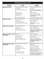
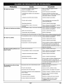
TROUBLE
CAUSE
Engine will not start
On/Off Stop Control is "OFF" position
Turn On/Off Stop Control to "ON"
Empty fuel tank
Fill fuel tank
Primer bulb wasn't pushed enough
Press primer bulb fully and slowly
5-7 times. Fuel should be visible in the
bulb
Fouled spark plug
Replace spark plug
Plugged spark arrestor
Clean or replace spark arrestor
Engine flooded
Use starting procedure WITHOUT
USING CHOKE
Old or improperly
Engine will not idle
Engine will not accelerate
Engine lacks power or stalls
when cutting
Cutting attachment
advance line
will not
REMEDY
Drain fuel tanWadd fresh fuel mixture
mixed fuel
Old or improperly mixed fuel
Drain fuel tanWadd
Dirty air filter
Clean or replace air filter
Carburetor misadjusted
Adjust carburetor
Cutting attachment bound with grass
Stop engine and clean cutting
attachment
Old or improperly mixed fuel
Drain fuel tanWadd
Dirty air filter
Clean or replace air filter
Plugged spark arrestor
Clean or replace spark arrestor
Improper carburetor adjustment
Take to any nonroad engine repair
establishment,
individual or authorized
service dealer for carburetor
adjustment
Dirty air filter
Clean or replace air filter
No oil in fuel or old fuel
Drain fuel tanWadd fresh fuel mixture
Fouled spark plug
Replace spark plug
Plugged spark arrestor
Clean or replace spark arrestor
Improper carburetor adjustment
Take to any nonroad engine repair
establishment, individual or authorized
service dealer for carburetor
adjustment
Cutting attachment
out of cutting
line
fresh fuel mixture
fresh fuel mixture
Refill cutting attachment
cutting line
with new
Reel bound up
Clean reel and rewind line
cutting attachment dirty
Clean reel and reel housing
Indexing teeth worn or burred
Replace reel and reel housing
Line welded
Disassemble, remove at the welded
section and rewind the line
Line twisted
when refilled
Not enough line is exposed
-24-
Disassemble
and rewind line in reel
Push the Bump Knob TM and pull out
line until 4 in. (102 mm) of the line is
outside of the cutting attachment
- 25 -
California / EPA Emission Control Warranty Statement;
Your Warranty Rights and Obligations
The California Air Resources Board, EPA (Environmental Protection Agency), and Sears, Roebuck, and Co. are pleased to
explain the emission Control System Warranty on your 2000 and later small off-road engine. In California and the 49 states,
new small off-roed engines must be designed, built and equipped to meet the state's stringent anti-smog standards. Sears
must warrant the emission control system on your small off-road engine for the periods of time listed below provided there
has been no abuse, neglect or improper maintenance of your small off-road engine.
Your Emission control system may include parts such as the carburetor or fuel-injection system, the ignition system, and
catalytic converter. Also included may be hoses, belts, connectors and other emission-related assemblies.
Where a warrantable condition exists, Sears will repair your small off-roed engine at no cost to you including diagnosis, parts
and labor.
The 2000 and later small off-road engines are warranted for two years. If any emission-related
defective, the part will be repaired or replaced by Sears.
part on your engine is
Owner's Warranty Responsibilities:
• As the small off-road engine owner, you are responsible for the performance of the required maintenance listed in your
operator's manual. Sears recommends that you retain all receipts covering maintenance on your small off-roed engine, but
Sears cannot deny warranty solely for the lack of receipts or for your failure to ensure the performance of all scheduled
maintenance.
• As the small off-roed engine owner, you should however be aware that Sears may deny you warranty coverage if your small
off-road engine or a part has failed due to abuse, neglect, improper maintenance or unapproved modifications.
• You are responsible for presenting your small off-road engine to an Authorized Sears Service Center as soon as problem
exists. The warranty repairs should be completed in a reasonable amount of time, not to exceed 30 days.
If you have any questions regarding your warranty rights and responsibilities, you should call 1-800-827-6655.
Manufacturer's Warranty Coverage:
• The warranty period begins on the date the engine or equipment is delivered to the retail purchaser.
• The manufacturer warrants to the initial owner and each subsequent purchaser, that the engine is free from defects in
material and workmanship which cause the failure of a warranted part for a period of two years.
• Repair and replacement of warranted part will be performed at no charge to the owner at an Authorized Sears Service
Center. For the nearest location please contact Sears at: 1-800-827-6655.
• Any warranted part which is not scheduled for replacement, as required maintenance or which is scheduled only for regular
inspection to the effect of "Repair or Replace as Necessary" is warranted for the period. Any warranted part which is
scheduled for replacement as required maintenance will be warranted for the period of time up to the first scheduled
replacement point for that part.
• The owner will not be charged for diagnostic labor which leads to the determination that a warranted part is defective. If the
diagnostic work is performed at an Authorized Sears Service Center.
• The manufacturer is liable for damages to other engine components caused by the failure of a warranted part still under
warranty.
• Failures caused by abuse, neglect or improper maintenance are not covered under warranty.
• The use of edd-on or modified parts can be grounds for disallowing a warranty claim. The manufacturer is not liable to cover
failures of warranted parts caused by the use of edd-on or modified parts.
• In order to file a claim, go to your nearest Authorized Sears Service Center. Warranty service or repairs will be provided at all
Authorized Sears Service Centers.
• Any manufacturer approved replacement part may be used in the performance of any warranty maintenance or repair of
emission related parts and will be provided without charge to the owner. Any replacement part that is equivalent in
performance or durability may be used in non-warranty maintenance or repair and will not reduce the warranty obligations of
the manufacturer.
• The following components are included in the emission related warranty of the engine, air filter, carburetor, primer, fuel lines,
fuel pick up/fuel filter, ignition module, spark plug and muffler.
- 26-
I
I
L\
@
@
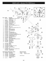
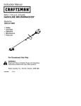
Item
1
2
3
4
5
Part No.
753-04105
8
791-180350B
791-180351
791-180226
791-182160
791-182161
791-182162
753-04106
9
10
11
12
13
14
15
16
791-810675
791-181860
791-181801
753-1196
791-884451
753-04107
753-1208
753-04108
17
18
19
20
21
22
23
24
25
791-812134
791-181802
791-182529
791-181168
791-882039
791-145308
791-153520
791-181861
791-182064
26
27
28
29
30
3!
32
33
34
791-180929
791-181065
791-181597
791-813102
791-181441
791-611061
791-181079
791-813103
791-182222
6
7
Description
Air Cleaner/Muffler
(includes 2 & 42)
Air Cleaner Filter
@
Cover Assembly
Item
35
36
37
Carburetor Mounting Screw Assembly
Wavey Washer
Choke Lever Assembly (includes 6)
Choke Knob and Screw
38
39
Choke Lever and Plate (includes 5)
Carburetor Assembly w/Umiter Caps
(includes 9 &21)
Carburetor Gasket
Carb Mount Screw
46
41
42
43
44
45
46
47
Primer and Hose Assembly
Carb Mount Assembly (includes 15)
Reed Assembly
Power Shaft Assembly
Carburetor Mount Gasket
48
49
5O
51
52
53
Crank Case Service Assembly
(includes 10, 14 & 24)
Rear Mounting Pad
Fuel Tank Assembly (includes 19-21)
Fuel Cap Assembly
Fuel Return Line
Fuel Line Assembly
Front Mounting Pad
Shroud Assembly
Shroud Screw
Shroud Extension and Stand
Flywheel Assembly
Spacer
Recoil Pulley Assembly
Recoil Spring
Pulley Retainer Assembly
Rope Guide
Pull Handle
Rope
Starter Housing Assembly(includes
Part No.
791-181862
791-182368
791-182369
791-153592
791-181798
791-181070
791-145569
791-181345
791-182798
791-611063
753-04109
791-610311B
791-182065
753-04110
791-147575
753-04111
753-1207
753-1197
791-182723
753-04113
791-180091
753-1209
753-04112
- 27 -
Clutch Rotor Assembly
Clutch Drum Assembly
Clutch Cover Assembly (includes 40-42)
Bolt
Anti Rotation Screw
Cover Screw
Lead Wire & Sleeve Assembly
Ground Tab
Module Assembly
Spark Plug
Exhaust Gasket
791-610309
791-18599
Muffler Assembly
Muffler Mounting Bolt Assembly
Cylinder Assembly(includes 53)
Piston and Rod Assembly
Cylinder Gasket
Cylinder Bolt
O.E.M. Carburetor Repair Kit (Zama)
Gasket Diaphragm Repair Kit (Zama)
Piston Ring Set
Short Block Assembly (includes 14, 16, 46, 50-53)
Crankcase Seal
Clutch Springs (Q_. 2)
791-182747
Spark Arrestor Kit
not shown
28-35)
Description
Housing Screw
Clutch Washer
®
/
®
Item
Part No.
Descd il_tien
1
753-04118
2
3
4
5
6
7
8
9
10
11
791-00041
753-04119
791-182690
791-182673
791-182877
791-610327
791-181808
791-181099
791-612831
791-612021
Throttle Housing and Trigger Assembly
(includes 2-4)
Throttle Trigger Lock-Out
Throttle Trigger
Throttle Trigger Spring
Switch Assembly
Throttle Cable Assembly
Harness Clip
Drive Shaft Housing
J-Handle Assembly (includes 10 & 11)
Grip
Tube Closure
12
13
791-683295
791-181811
Handle Bracket Assembly
Screw
14
15
16
17
18
19
791-181812
791-181813
791-181814
791-181815
791-145569
791-181817
Upper Handle Clamp
Middle Handle Clamp
Lower Handle Clamp
Nut
Anti-Rotation Screw
Lower Flexible Drive Shaft
20
21
22
23
24
25
791-182200
791-182193
791-182195
791-145569
791-147492
791-182196
Shield Mount Screw Assembly
2 piece GearboxAssembly
(includes 20-23)
Gearbox Mounting Hardware
Anti-Rotation Screw
Blade Shield/Shield Mount
Blade Driver
26
27
28
29
30
31
791-683304
753-1191
791-682061
791-147490
791-612483
791-683301
32
791-612026
Shield Mounting Screw
Shield and Blade Assembly (includes 28)
Blade Assembly
Retaining Washer
Spool Shaft
Outer Spool and
Eyelet Assembly
Retainer
33
34
791-610636B
791-147495
Sprin 9
Inner Reel
35
36
37
38
791-180814B
791-145873B
791-181695
791-181699
Bump Head Knob Assembly
4-Tooth Blade
44 Tooth Saw Blade
Nut
791-180014B
791-613226
791-181694
Blade Retaining Kit (includes 29 & 38)
Locking Rod Tool
Shoulder Harness
2 Piece Gearbox Assembly Parts - Item 26
39
40
41
42
43
44
791-182191
791-182192
791-182194
791-182199
791-182198
791-182197
45
753-1159
Left Housing
Right Housing
Pinion Gear Assembly
Output Shaft Bushing
Output Shaft Gear
Output Shaft Assembly
(includes 41 & 42)
O-Ring
2_(
@
\
(includes 13-18)
I
@
_7
Optional Accessories
71-85614
Bulk Line
71-36549
Craftsman 2-Cycle Oil
Items Not Shown
- 28 -
j
@
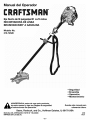
Manual del Operador
[RAFTSMAN.+
Eje Recto de18 pulgadas/31 cc/2 ciclos
RECORTADORA DE LINEA
BRUSHWACKER ®A GASOLINA
Modelo No.
316.74520
•
•
•
•
lea este manual y siga sus Reglas de seguridad
ADVERTENCIA:
antes de usar este producto,
e Instrucciones de operacibn,
Sears, Roebuck,
and Co., Hoffman
Seguridad
Ensamble
Operacibn
Mantenimiento
Guarde este manual para
referencia futura.
Estates, IL 60179 USA
2/02
Revl
MANUAL DEL OPERADOR, PARTE N ° 769-00066
IMPRESO EN LOS EE.UU.
- E1 -
Declaraci6n de Garantia Limitada
E2
Mantenimiento
Advertencia de la Proposici6n 65 de California
E2
Parachispas
Normas para una operaci6n segura
Contenidos de la Bolsa de Piezas
E2
E3
E7
Servicio y Ajustes
Almacenamiento
Ensamble
E8
Operaci6n
E12
Especificaciones
Resoluci6n de Problemas
E17
E19
E23
E23
E24
EPA E27
GARANTIA TOTAL DE UN AI_IO PARA LA CORTADORA DE MALEZAS / RECORTADORA
CRAFTSMAN@ BRUSHWACKER®
A GASOLINA
Sears reparar& sin costo alguno cualquier defecto de material o de mano de obra durante un periodo de un are a partir de la fecha de
compra, siempre que esta Cor_adora de Malezas / Recortadora a gasolina Craftsman Brushwacker haya recibido el mantenimiento,
lubricaci6n y puesta a punto de acuerdo con las instrucciones de operaci6n y mantenimiento indicadas en el Manual del Operador.
Esta garantia excluye la linea de nil6n, bujias de encendido y filtro de aire, asi como las piezas que se gastan durante el
uso normal.
Siesta Cortadora de Malezas / Recor_adora Brushwacker
Siesta Cortadora de Malezas / Recor_adora Brushwacker
partir de la fecha de compra.
se utiliza con fines comerciales, esta garantia tendr& una vigencia de 90 dias.
se utiliza con fines de alquiler, esta garantia tendr& una vigencia de 30 dias a
Esta garantia tendr& validez solamente mientras esta unidad sea utilizada en los Estados Unidos.
EL SERVlCIO A TRAVES DE LA GARANTiA ESTAR/_ DISPONIBLE CUANDO LLEVE LA CQRTADORA DE MALEZAS / RECQRTADORA
BRUSHWACKER A SU CENTRO DE SERVlCIO SEARS M,&S CERCANO EN LOS ESTADOS UNIDOS.
Esta garantia le otorga derechos legales especificos, yes posible que usted tambi6n tenga otros derechos que varian de acuerdo al estado.
Sears, Roebuck and Co., D/817 WA, Hoffman Estates, IL 60179
LAS EMISIONES
DEL MOTOR DE ESTE PRODUCTO
CONTIENEN
SUBSTANCIAS
QUJMICAS QUE EL
ESTADO DE CALIFORNIA
CONOCE COMO
CAUSANTES DE CANCER, DEFECTOS DE
NACIMIENTO
U OTROS DAI_IOS REPRODUCTIVOS,
NOTA: Para los usuarios en tierras forestales de los EE.UU. y en los estados de California, Maine, Oregon y Washington. Toda la
tierra forestal de EE.UU. y del estado de California (C6digos de Recursos PQblicos 4442 y 4443), Oregon y Washington requieren, por
ley, que ciertos motores de combusti6n operados en Areas de maleza forestales o recubier_as con c6sped est6n equipados con un
parachispas, que sean mantenidos en buenas condiciones de funcionamiento, o que el motor sea construido, equipado y mantenido
para la prevenci6n de incendios. Consulte con sus autoridades estatales o locales acerca de las normas relacionadas con dichos
requisitos. Si no cumple con estos requisitos, usted podrfa ser legalmente responsable o recibir una multa. Esta unidad viene
equipada de fbbriea con un paraehispas. Si necesita cambiarlo, solicite que su centre Sears de servicios instale el aceesorio
N° 182747, parachispas.
NOTA ESPECIAL: La exposicion a vibraciones mediante el use prolongado de herramientas manuales operadas a gasolina puede
causar daSos en los vases sanguineos o nervios de los dedos, manos y ar_icu]aciones en las personas con predisposicion a problemas
de circulaci6n o a inflamaciones excesivas. El uso prolongado durante el tiempo frio ha sido relacionado con daSos de vasos sanguineos
en personas sanas. Si ocurren sintomas come entumecimiento, dolor, p6rdida de fuerza, cambio en el color o textura de la piel, o p6rdida
de sensaci6n en los dedos, manes o arLiculaciones, abandone el use de esta herramienta y obtenga atenci6n m6dica. Un sistema de
antivibraci6n no garantiza la prevenci6n de estos problemas. Los usuarios que operan herramientas motrices en forma continua y regular
deben controlar de cerca su condici6n fisica y la condici6n de esta herramienta.
- E2 -
Los simbolos de seguridad se utilizan para Ilamar su
atenci6n sobre posibles peligros. Los slmbolos de
seguridad y sus explicaciones merecen toda su atenci6n
y comprensi6n. Los simbolos de seguridad no elirninan
ningQn peligro por si mismos. Las instrucciones o
advertencias que ofrecen no substituyen las medidas
adecuadas de prevenci6n de accidentes.
SJMBOLO
,_
PELIGRO: El no obedecer una advertencia de
seguridad puede conducir a que usted u otras
personas sufran graves lesiones. Siga siempre las
precauciones de seguridad para reducir el riesgo de
incendio, descarga el6ctrica y lesiones personales.
ADVERTENClA:
El no seguir una advertencia de
seguridad puede conducir a que usted u otras
personas sufran lesiones. Siga siempre las
precauciones de seguridad para reducir el riesgo de
incendio, descarga el6ctrica y lesiones personales.
SIGNIFICADO
Indica peligro, advertencia o precauci6n.
SiMBOLO
ALERTApara
DEevitar
SEGURIDAD:
Debe prestarDEatenci6n
sufrir
graves lesiones personales. Puede ser
utilizado junto con otros simbolos o figuras.
NOTA: Le ofrece informaci6n o instrucciones que son
esenciales para la operaci6n o mantenimiento
del equipo.
IMPORTANTE
LEA TODAS
1_1_
INFORMACI6N
LAS INSTRUCCIONES
seguridad puede conducir a daSo patrimonial o a que
usted u otras personas sufran lesiones personales.
Siga siempre las precauciones de seguridad para
reducir
el riesgo deEl
incendio,
el6ctrica de
y
PRECAUCI(_N:
no seguirdescarga
una advertencia
lesiones personales.
DE SEGURIDAD
w Oprima e! control del regulador y verifique que regrese a la
posici6n de minima en forma autom&tica. Haga todos los
ajustes 0 reparaciones antes de usar la unidad.
ANTES DE LA OPERACION
• Lea todas las instrucciones con cuJdado. Conozca bien los
controles y el uso correcto de la unidad.
ADVERTENCIAS
RECORTADORES
,, No opere esta unidad si est& cansado, enfermo, o bajo los
efectos del alcohol, drogas o mea=camentos.
DE SEGURIDAD
A GASOLINA
PARA
LOS
ADVERTENCIA: La gasolina es muy inflamable y sus gases
pueden explotar si se encienden. Tome !as siguientes
precauoiones:
" Los nifios y los adolescentes menores de 15 a6os no deben
operar las un=aaaes, excepto por los adolescentes gu=ados
por un adulto.
w Guarde el combustible en envases que hayan sido
diseSados y aprobados para el a!macenarniento de dichos
materiales.
• Todas las protecciones y accesonos de seguridad deben
estar instalados en torma correcta antes de operar la unidad.
Antes de Ilenar el tanque de combustible, apague siempre el
motor y espere que se enfrie. No retire nunca la tapa del
tanque de combustible ni cargue combustible mientras el
motor est6 caliente. No opere nunca la unidad sin la tapa del
combustible
colocada firmemente en su lugar. Afloje la tapa
del combustible lentamente para disipar la presion del
tanque.
• Inspecc_one la unidad antes de su uso. Cambie las partes
daSadas. Inspeccione si hay perdidas de combustible.
Verifieue aue todos los sujetadores esten en su lugar y
asegurados. Cambie las parses que esten auebradas.
cascadas o daSadas de cualquler moao. No opere esta
un_eaa con 3ar_es flojas ni daSadas.
Q Mezcle y cargue el combustible en un &rea exterior bien
ventilada donde no haya chispas ni llamas. Quite lentamente
la tapa del combustible s61o despu6s de apagar el motor.
No fume mientras carga o mezcla el combustible. Umpie de
inmediato todo el combustibl e que se haya derramad0.
• Use s61o linea de reemplazo Craftsman@ genuina de 0.095
pulgadas (2.41mm) de di&metro. Nunca use linea reforzada
con metal, cable o soga, e_c., ya que pueden romperse
convertlrse en proyectiles peligrosos.
• Tenga en cuenta el nesgo de lesiones en la cabeza, las
manos y los pres.
t Evite crear una fuente de encendido por combustible
derramado. No arranque el motor hasta que se hayan
disipad0 !0S yap ores del combustible.
• Limpie el _rea de corse antes de cada uso. Saque todos los
obje_os como rocas, vidrios rotos, clavos, alambre o cuerda
que puedan saint despedidos o enredarse en el accesorio de
coEe.
Aleje la unidad a por Io menos t0 pies (3 m.) del lugar de
carga de combustible antes de arrancar el motor. No fume,
mantenga las chispas y las llamas abier_as lejos del Area
mientras carga el combustible u opera la unidad.
• Aleje del &rea a todos los niSos, espectadores y an=males
domesticos. Uantenga toaos los niSos, espectadores
animales dom6sticos a un rad=o de por Io menos 15 m (50
pies); aun asi pueae exisur un nesgo de objetos despedidos
contra los espec[aaores. __osespectadores deben usar
protecci6n para sus ojos. Si algu=en se le acerca, pare el
motor y el accesorio de cotte de inmediato.
- E3 -
DURANTE
LAOPERACION
• Si goipea o se enreda con algQn objeto extrafio, apague el
motor de inmediato y verifique si hay daSos. No opere la
unidad antes de reparar los daSos. No opere la unidad si
tiene piezas flojas o daSadas. No opere la unidad con una
cuchilla torcida, rajada o desafilada. Deseche las cuchillas
que est6n torcidas,encorvadas,
rajadas o rotas.
• No arranque ni opere la unidad en una sala o edificio
cerrado. Los gases de escape de mon6xido de carbono
pueden ser letales en un &tea cerrada. Opere esta unidad
s61o en un &rea exterior bien ventilada.
• Use lentes o gafas de proteccidn
normas ANSI Z87.1, y protecci6n
mientras opere esta unidad. Use
o para protegerse contra el polvo
polvo.
que cumplan con las
para sus oidos/audicidn
siempre una m&scara facial
si la operaci6n levanta
• Apague el motor para realizar todo el mantenimiento,
reparaciones o cambio del accesorio de corte u otros
accesorios.
• Use solamente repuestos legitimos cuando realice el
servicio de esta unidad. Estas piezas est&n disponibles en
su distribuidor autorizado. No use piezas, accesorios ni
auxiliares que no hayan sido diseRados para esta unidad. Su
uso puede conducir a que el usuario sufra graves lesiones o
al daRo de la unidad y a la invalidaci6n de su garant[a.
• Use pantalones largos y gruesos y guantes. No vista ropa
holgada, alhajas, pantalones cortos, sandalias ni est6
descalzo. Asegure su cabello sobre el nivel de los hombros.
• Ajuste la manija auxiliar a su medida de modo que le brinde
el mejor agarre.
• Mantenga la unidad libre de vegetaci6n y otros materiales.
Pueden alojarse entre el accesorio de corte y la protecci6n.
• AsegQrese de que el accesorio de corse no est& en contacto
con ningQn objeto antes de arrancar la unidad.
• Para reducir el riesgo de incendio, cambie los silenciadores
y amortiguadores de chispas defectuosos, mantenga el
motor y el silenciador libre de pasto, hojas, grasa excesiva o
acumulaciones de carbono.
• La protecci6n accesoria de corte debe estar siempre
colocada en su lugar mientras opere la unidad. No opere la
unidad con las dos lineas de corte extendidas, y la linea
correcta instalada. No extienda la I[nea de corte m&s all& de
la Iongitud de la protecci6n.
MIENTRAS
DE CORTE
• Lea y comprenda todas las advertencias
de operar esta unidad.
• Esta unidad cuenta con un embrague. El accesorio de
corte permanece estacionario cuando el motor esta en
marcha lenta. Si no Io hace, haga ajustar la unidad por
un establecimiento de reparaci6n, persona o
proveedor de servicio autorizado que arregle motores
para uso fuera de la carretera.
de seguridad antes
• Use siempre el arn6s del hombro mientras opere el
accesorio de la cuchilla de corte.
• Mantenga siempre la manija auxiliar entre el operador y el
accesorio o cuchilla de corte.
• Use la unidad Qnicamente con la luz del d[a o con buena luz
artificial.
• NUNCA corte con la(s) cuchilla(s) ubicada a m&s de 30
pulgadas (76 cm.) o m&s de altura sobre el nivel del suelo.
• Evite arrancar la unidad accidentalmente. Col6quese en
posici6n de inicio siempre que tire de la cuerda de arranque.
El operador y la unidad deben estar en una posici6n estable
al comenzar. Yea Instrucciones de encendido y apagado en
la secci6n de Operaci6n.
• Cuando la cuchilla giratofia hace contacto con un objeto que
no corta de inmediato, puede ocurrir un impulso de la
cuchilla. El impulso de la cuchilla puede ser Io
suficientemente violento como para hacer que la unidad y/o
el operador sean impulsados en cualquier direcci6n, y
posiblemente perder el control de la unidad. El impulso de la
cuchilla puede ocurrir si la cuchilla se tropieza, se traba o se
atasca. Es m_s posible que esto ocurra en _reas donde es
dificil vet el material que est_ cortando.
• Use la herramienta adecuada. No use esta unidad para
ninguna tarea para la cual no ha sido diseSada.
• No se estire demasiado.
equilibrio adecuados.
USA LA CUCHILLA(S)
Mantenga siempre una posici6n y
• Sostenga siempre la unidad con ambas manos mientras
est6 en funcionamiento. Sostenga con firmeza tanto el
mango como la manija auxiliar.
• No corte nada de m&s de 1/2 puigada de espesor con la
cuchilla Craftsman de 4 dientes, o de m&s de 2 pulgadas
de espesor con la cuohina de sierra de 44 dientes, ya que
pudiera ocurrir una reacci6n de reculada violenta.
• Mantenga las manos, la cara y los pies lejos de todas las
partes mdviles. No intente tocar ni detener el accesorio de
corte mientras gira.
• NO intente tocar ni detener la cuchilla mientras est_ girando.
• No toque el silenciador ni el cilindro. Estas partes se
calientan mucho con la operaci6n. Luego de apagarlas
permanecen calientes durante un corto tiempo.
• Una cuchilla en deslizamiento puede causar graves lesiones
mientras continua girando luego de apagar el motor o de
soltar el gatillo del regulador. Mantenga buen control hasta
que la cuchilla se haya detenido pot completo.
• No opere el motor a una velocidad mayor que la necesaria
para cortar, recortar o recortar los bordes. No haga
funcionar el motor a alta velocidad mientras no est&
cortando.
• NO afile la(s) cuchilla(s) de corte. El afilar una cuchilla puede
hacer que la punta de la cuchilla se rompa mientras se est_
usando. Esto puede resultar en lesi6n personal grave.
Reemplace la(s) cuchilla(s) desafilada(s).
• Apague siempre el motor cuando demore el corte o mientras
camina entre zonas de corte.
- E4 -
• Si siente una vibraci6n excesiva, apague el motor DE
INMEDIATO. La vibraci6n indica que hay problemas.
Inspeccione si hay tuercas o pemos flojos o dafios antes de
continuar. Repare o cambie las pares afectadas segQn sea
necesario.
• Espere que el motor se enfrie antes de guardar o transportar
la unidad. Asegerese de que la unidad est6 segura al
transpor_arla.
* Guarde la unidad bajo Ilave en un lugar adecuado y seco
para evitar que sea usada per personas no autorizadas y se
daSe, fuera del alcance de los nifios.
DESPUES DEL use
Nunca moje ni rocie la unidad con agua ni con ningQn otro
I[quido. Mantenga las manijas secas, limpias y sin residues.
Limpie la unidad luego de cada use. Vea las secciones de
Mantenimiento y Almacenamiento.
• Limpie la(s) cuchilla(s) de corte con un limpiador dom6stico
para eliminar toda acumulaci6n de goma. Lubrique la(s)
cuchilla(s) con aceite de m&quina para evitar que se oxide(n).
• Guarde la cuchilla de corte bajo Ilave en un &rea adecuada
para evitar que sea utilizada per personas no autorizadas y
se daSe.
OTRAS ADVERTENCIAS
Guarde estas instrucciones. ConsQItelas con frecuencia y
utilicelas para enseSar a otros usuarios. Si le presta esta
unidad a alguien, pr6stele tambi6n estas instrucciones.
DE SEGURIDAD
GUARDE
• No guarde nunca la unidad con combustible en el tanque en
un edificio donde los gases puedan Ilegar a una llama
abierta o a una chispa.
S|MBOLOS
DE SEGURIDAD
ESTAS INSTRUCCIONES
E INTERNACIONALES
Este Manual del Operador describe los simbolos y fJguras ee seguridad e _nternac_onales que pueden aparecer en este producto. Lea e
Manual del Operador para obtener informaci6n correcta acerca de la seguridad, ensamble, operaci6n y mantenimiento y reparac_on.
SJMBOLOS
A
©
e
SIGNIFICADOS
• S[mbolo
de Alerta
ndica peligro,
de Seguridad
advertencia,
• Lea el Manual
o precauci6n.
Puede ser utilizado
con otros
simbolos.
del Operador
El no seguir las instrucciones de operaci6n y las precauciones de seguridad contenidas en el
Manual del Operador puede conducir a graves lesiones. Lea el Manual del Operador antes de
arrancar u operar esta unidad.
• Use protecci6n
ocular y auditiva
ADVERTENCIA: Los objetos arrojados per la unidad y el ruido fuerte pueden causar graves
esiones oculares y perdida auditiva. Utilice proteccion ocular que cumpla con las normas
ANSI Z87.1 y protecci6n auditiva cuando opere esta unidad.
• Los objetos arrojados per la unidad y la cabeza
causar graves lesiones
ff
junto
No opere esta unidad si la protecci6n
3ieza de corte en movimiento.
• Mantenga
alejados
de corte en movimiento
pueden
no esta colocada en su lugar. MantAngase alejado de la
a los nihos
ADVERTENCIA: Mantenga a todos los espectadores, en especial aniSos y animales
domAsticos a per Io menos 50 3ies (15 m) del Area de corte. Detenga la unidad de inmediato, s
alguien se le acerca.
- E5 -
S|MBOLOS
SIGNIFICADOS
5-7x
• BombUla del cebador
N
Presione la bombilla del cebador completa y lentamente, de 5 a 7 veces.
• Combustible
sin Plomo
Use siempre combustible
• Indicador
limpio y nuevo sin plomo.
de Aceite
Consulte el manual del operador para informarse sobre el tipo adecuado de aceite.
A
I÷1
B
C
• Control
del Obturador
A Posici6n de Obturaci6n COMPLETA
B Posici6n de Obturaci6n PARCIAL
C PosiciSn de FUNCIONAMIENTO
• ADVERTENCIA
DE SUPERFICIE
CALIENTE
No toque el motor ni el silenciador. Estas partes se calientan mucho con la operaci6n.
Despu6s de apagadas, permanecen calientes durante un rato.
• Control
de ENCENDIDO
Y APAGADO
ENCENDIDO / ARRANQUE / FUNCIONAMIENTO
• Control
de ENCENDIDO
Y APAGADO
APAGADO o PARADO
• CUCHILLA
AFILADA
ADMERTENCIA:
El protector accesorio de corte contiene una cuchilla afilada.
Para evitar graves lesiones personales, no toque la cuchilla. No toque los bordes
de la cuchilla de sierra de 44 dientes. Utilice guantes.
• CORTADORAS
DE MALEZA
Cambie
la(s) cuchUla(s)
desafilada(s)
No afile la(s) cuchilla(s) de corte. El afilar la cuchilla puede causar que la punta de
la(s) cuchilla(s) se desprenda mientras estA en uso. Esto puede originar graves
lesiones personales.
•
SEGURIDAD
DE LA RECORTADORA
/ CORTADORA
DE MALEZAS
ADVERTENCIA: Los objetos que salen despedidos y la cortadora giratoria pueden causar
graves lesiones. Mantenga a los espectadores, especialmente a los nidos y animales
dom6sticos a no menos de 50 pies (15 m) de distancia del Area de core. Debe utilizar el
protector accesorio de corte mientras use el accesorio de corte de la recortadora.
!
- E6 -
Varilla de
cierre
Protectoraccesorio
de corte de 18"
Manual del operador
(3) Tornillos (1/4-20 x 1/2)
- para el protector accesorio de
corte
Cuchilla de 4 dientes
Tuerca de la cuchina
(tamat_oreal)
Arn_s para el hombro
Botella de
aceite
- E7 -
Cuchilla de sierra
de 44 dientes
Su unidad puede ser ensamblada en tres (3) configuraciones:
CUCHILLA DE 4 DIENTES -- se usa para cortar
cesped, hierbas y arbustos le_osos de hasta 1/2
pu/gada de di&metro.
ACCESORIO DE CORTE -- se usa para cortar
cesped y hierbas deigadas.
CUCHILLA DE SIERRA DE 44 DIENTES -- se usa
para cortar cesped, hierbas y arbustos lefiosos de hasta
2 pulgadas de di&metro.
CONTENIDO
INFORMACI(_N
DE LA CAJA
• Cortadora de malezas / Recortador
ACERCA
DEL
ENSAMBLE
Para asegurar una operaci6n segura y correcta de su
unidad, todas las partes y piezas que ensamble deben
estar ajustadas con firmeza.
• Manija auxiiiar con ias abrazaderas superior y media
colocadas
• Bolsa de piezas
- E8 -
HERRAMIENTAS
NECESARIAS
PARAELENSAMBLE
Manija Au xiliar_
• Llave de boca cerrada de 5/8 de pulgada (si instala la cuchilla)
• Destornillador
de v&stago piano
• Destornillador
Phillips grande
INSTALACI_)N
Y AJUSTE
DE LA MANIJA
(4)
AUXILIAR
superior
Instalaci6n
1.
Abrazadera
Retire los tornillos y las tuercas, asi como las abrazaderas
superior y media que se instalaron en la manija auxiliar para
el envio.
2.
Coloque la manija auxiliar entre la abrazadera media y la
abrazadera superior (Fig. 1).
3.
Mientras sostiene las tres piezas juntas, instale los cuatro
(4) tornillos a trav6s de la abrazadera superior en la
abrazadera media.
Abrazadera
media
inferio=
Tuercas_
-_
Fig. 1
NOTA: Los orificios de la abrazadera media y superior se
alinear&n s61o cuando se ensamble en forma correcta.
4.
Coloque las abrazaderas y la manija auxiliar por encima
del bastidor del eje y sobre la abrazadera inferior.
5.
Sostenga cada tuerca hexagonal en el hueco de la
abrazadera inferior con un dedo. Comience a colocar los
tornillos con un destornillador Phillips grande. No los
apriete hasta ajustar la manija.
Ajuste
6.
Afloje los tornillos de modo que la manija auxiliar pueda
moverse f&cilmente en el ensamble de abrazaderas. No
saque los tornillos ni las tuercas.
7.
Deslice la manija auxiliar hacia dentro o hacia fuera hasta
que la fiecha o linea blanca de la calcomania toque el
ensamble de abrazaderas (Fig. 2).
8.
Mientras sostiene la unidad en posici6n de operaci6n
(Fig. 3), coloque la manija auxiliar en la posici6n que le
brinde el mejor agarre.
9.
Ajuste los tornillos de la abrazadera en forma pareja hasta
que la manija auxiliar est6 firme.
REMOCION E INSTALACION
ACCESORIO DE CORTE
Fig. 2
DEL PROTECTOR
Inetale el protector accesorio de corte cuando use la
unidad como recortador de cdsped.
Instale el protector accesorio de corse con los tres (3) tornillos
(1/4-20 x 0.50) (Fig. 4) en el protector de la cuchilla con un
destomillador
adecuado. Ajuste los tornillos.
Fig. 3
PRECAUCI(_N: Para evitar una grave lesi6n personal
y el da_o a la unidad, el protector accesorio de corte
debe ser usado cuando opere esta unidad con el
accesorio de corte.
Torninos
Bastidor de los
engranajes
Saque el protector accesorio de corte cuando use la
unidad como cortador de malezas.
Proteccibn de
la cuchina
ADVERTENCIA: El protector accesorio de corte NO
debe estar instalado cuando use la unidad con una
cuchilla. Saque el protector accesorio de corte antes
de sacar o instalar la cuchilla.
Protector
accesorio
de corte
Retire el protector del accesorio de corte del montaje del
protector quitando los tres (3) tornillos con un destornillador
adecuado (Fig. 4). AImacene las piezas para su uso futuro.
Fig. 4
- E9 -
REMOCION DEL ACCESORIO DE CORTE E
INSTALACI6N DE LA CUCHILLA
Ejedesalida
ADVERTENCIA: Para evitar graves lesiones
personales, use siempre guantes al manejar, sacar
o instalar !a(s) cuchi!la(s) o el accesorio de corte.
45,
_
_
Ranura de la __----------_-_J.}
varilla de cierre
__<_
Orificio
ADVERTENCIA: El bastidor de los engranajes se
calienta mucho despu6s de largos perfodos de uso.
Para evitar graves lesiones personales, n0 toque eI
bastidor hasta que se haya enfriado.
del
_
,__
casquino del __
Marina de
_
cierre
V
Fig. 5
Siga las instrucciones siguientes y consulte las advertencias
de seguridad para sacar el accesorio de corte e instalar la(s)
cuchilla(s) en forrna correcta.
Para sacar e instalar el accesorio de corte o la cuchilla,
coloque la unidad boca abajo sobre un banco de trabajo o
sobre el suelo.
Remocibn del protector accesorio
de corte
Yea Remoci6n e inetalaci6n del protector del accesorio de
corte en la secci6n de Ensamble.
Remocibn
del accesorio de corte
1.
Alinee el orificio del eje de salida con la ranura de la varilla
de cierre. InserLe la varilla de cierre a trav6s de la ranura en
el orificio del eje de salida (Fig. 5).
2.
Sostenga la varilla de cierre en su lugar junto al brazo de la
unidad (Fig. 6).
3.
Desenrosque el accesorio de corte del eje en sentido
horario (Fig. 7) y gu&rdelo para su uso futuro.
Fig. 6
Aocesorio de corte
'\
NOTA: El ret6n de la cuchilla ubicado debajo del accesorio de
corte set& utilizado para instalar la cuchilla de corte.
Instalaci6n
de las cuchillas
Ranura de la
varilla de cierre
NOTA: La cuchilla cortadora de maleza de 4 dientes es
reversible, y puede rever_irse retirando la cuchilla, d&ndole vuelta
y volviendo a instalarla, iLa cuchilla de sierra de 44 dientee NO
ee reversible, y sblo debe inetalarse de la forrna indicada!
4.
5.
Varilla de cierre
Fig. 7
Instale la cuchilla, el ret6n de la cuchilla y la tuerca (Fig. 8).
Inserte la varilla de cierre a trav6s de la ranura en el orificio
del eje de salida. Verifique que la cuchilla permanezca
plana y centrada contra el eje de salida mientras ajusta la
contratuerca en sentido antihorario (Fig. 9).
Tuerca
/
Ret_n de la
cuchilla
Protecci6n
de la cuchilla
Si tiene una Ilave de torsi6n, ajuste la tuerca a 325-335
pulg..libras (37-38 N.m), mientras sostiene la varilla de
cierre en la ranura.
Si no tiene una Ilave de torsi6n, sostenga la varilla de cierre
en la ranura. Gire la tuerca en sentido antihorario con una
Ilave de boca cerrada de 5/8 de pulgada o con una Ilave de
casquillo hasta que la tuerca haga contacto firme contra la
arandela y la cuchilla est6 ajustada sin huelgo. Verifique que
el ensamble de la cuchilla est_ bien instalado, luego gire la
tuerca de 1/4 a 1/2 vuelta m&s (Fig. 9).
6.
Marina de
cierre
Fig. 8
Saque la varilla de cierre.
_,
contra
el eje de salida
luegoque
de laajustar
Si
ADVERTENCIA:
Verifique
cuchillala tuerca.
est6 plana
la cuchilla est& descentrada, la unidad se daSar& con
la vibraci6n y la cuchilla podr& salir despedida, Io
cual puede causar graves lesiones personales.
A
A_,
ADVERTENCIA: No afile ninguna de las cuchillas de
corse. E! afilar las cuchillas puede hacer que la punta
de una cuchilla se rompa mientras est& en uso. Esto
puede resultar en lesiones personales graves para
usted o para los dem&s.
Cuchilla de sierra
de 44 dientes
1/4,1/2 vuelta
Fig. 9
- El0 -
REMOCION DE LA CUCHILLA E
INSTALACIeN DEL ACCESORIO DE CORTE
personales,
use siempre
guantes
al lesiones
manejar, sacar
ADVERTENCIA:
Para evitar
graves
o instalar la(s) cuchilla(s) o el accesorio de corte.
_lb
ADVERTENCIA: El bastidor de los engranajes se
calienta luego de largos periodos de uso. Para evitar
una grave lesi6n personal, no toque el bastidor basra
que se haya enfriado.
4,
Ajuste el ames para el hombro para darle equilibrio de
modo que el accesorio de corte quede nivelado con el
suelo. Un ames para el hombro bien ajustado debe
sostener todo el peso de la unidad, dejando sus brazos y
manos libres para guiar y controlar el movimiento de corte.
5,
Extienda el ames tirando de la correa hacia abajo y
subiendo la hebilla. Acorte el ames tirando de la correa a
traves de la hebilla mientras mueve la hebilla hacia abajo
(Fig. 13).
ADVERTENCIA:
Para evitar lesiones personales
graves no conecte la correa del ames del hombro a
la unidad hasta que se haya encendido y usted se
encuentre en la posici6n de operaci6n. Siga siempre
las Inetruocionee de encendido como se describen
en la seccien de Operacibn.
Siga las siguientes instrucciones y consulte las advertencias
de seguridad para sacar la cuchilla e instalar el accesorio de
corte en forma correcta.
Para sacar e instalar el acesorio de corte o la cuchilla, coloque
la unidad boca abajo sobre un banco de trabajo o sobre el
suelo.
Remocibn
1.
Alinee el orificio del buje del eje con la ranura de la varilla de
cierre e inserte la varilla de cierre en el orificio del buje (Fig. 5).
2.
Sostenga la varilla de cierre en su lugar junto al brazo de la
unidad (Fig. 10).
3.
Mientras sostiene la varilla de cierre, afloje la tuerca de la
cuchilla gir&ndola en sentido horario con una Ilave de
casquillo o de boca cerrada de 5/8 de pulgada (Fig. 10).
4.
Saque la tuerca, el reten de la cuchilla y la cuchilla. Guarde
la tuerca y la cuchilla juntas en un lugar seguro para su
uso futuro. Guarde fuera del alcance de los nieos.
Instalacibn
5.
Afloje
de la cuchilla de corte
Fig. 10
del accesorio de corte
Accesorio
de corte
Alinee el orificio del buje del eje con la ranura de la varilla de
cierre e inserte la varilla de cierre en el orificio del buje del
eje (Fig. 5). Coloque el reten de la cuchilla en el eje de salida
con la superficie plana contra el buje del eje de salida segt_n
se ilustra en la Fig. 11. Enrosque el accesorio de corte en
sentido antihorario en el eje de salida. Ajuste bien.
6.
Saque la varilla de cierre.
7.
IInstate el protector accesorio de corte. Vea Remocien e
instalacibn del protector del accesorio de corte en la secci6n
de Ensamble.
Ret_n de la
cuchilla __
Buje del eje
de salida
Marina de
cierre
NOTA: El retch de la cuchilla debe estar instalado en el eje de
salida en la posicien ilustrada para que el accesorio de corte
funcione en forma correcta.
Fig. 11
PRECAUCIeN: Para evitar una grave lesi6n
personal y el daeo a la unidad, el protector accesorio
de corte debe ser usado cuando opere esta unidad
con el accesorio de corte.
AJUSTE DEL ARNES PARA EL HOMBRO
1.
Coloque el ames para el hombro sobre el hombro
izquierdo, el letrero de "Danger" en la espalda, y abroche
en la cadera derecha (Fig. 12).
2.
El gancho debe quedar aproximadamente 15 pulgadas
(38 cm) sobre su rodilla, o seis (6) pulgadas (15 cm) debajo
de su cintura (Fig. 12).
3.
Abroche el gancho en la abrazadera del ames del hombro
de la unidad (Fig. 14) y levante la unidad hasta la posicien
de operaci6n para comprobar que ajuste bien antes de
comenzar a operar la unidad (Fig. 12).
Fig. 12
- Ell -
×\
Fig. 13
CONOZCA SU CORTADORA
Abrazadera del arn_s
para el hombro
Fig. 14
DE MALEZAS / RECORTADOR
LEA ESTE MANUAL DEL OPERADOR Y LAS NORMAS DE SEGURIDAD ANTES DE OPERAR SU UNIDAD. Compare las
ilustraciones con su unidad para familiarizarse con la ubicaci6n de los diferentes controles y ajustes.
CONTROL DE
Guarde eete manual para su referencia futura.
OBTURACI(_N
TAPA DEL COMBUSTIBLE
ASA DE LA CUERDA
PROTECCI(SN
DE LA
CUCHILLA
DE ARRANQUE
BLOQUEO DEL
ACELERADOR
CONTROL DE
APAGADO ON/OFF
\_
\
BOMBILLA
DE CEBADO
CONTROL DEL
REGULADOR
DEL HOMBRO
BUJ|A DE ENCENDIDO
MANIJA AUXIUAR
/
CUCHILLADE
CONTROL DE APAGADO ON/OFF - se usa para encender (ON)
y apagar (OFF) el motor. El interruptor debe estar en la posici6n
\de arranque (START) cuando arranque el motor.
PROTECCI6N
DE LA
//_CHILI_
/
CEBADOR - extrae el aire de las tuberias del
y Ilena el carburador con combustible.
la velocidad del
motor para diversas condiciones
MANIJA AUXlMAR,
operaci6n.
se usa para sostener la unidad durante la
PROTECTOR ACCESORIO DE CORTE -. protege al operad0r
de los residuos que salen despedidos. Contiene la cuchilla
coRadora de linea para verificar que la linea no ee extienda m&s
all& de la Iongitud adecuada. El protector accesorio de core debe
estar instalado en todo momento que use el accesodo de core.
/
CUCHILLADE
4DIENTES
de corte.
BASTIDOR
DEL EJE
ACCESORIO DE CORTE - consiste en un bastidor para el
carrete, el carrete, el resorte, la perilla percusiva y la linea de core.
f
PROTECCION DE LA CUCHILLA - protege al operador contra
los residuos que salen arrojados. La protecci6n de la cuchilla debe
estar instalada en todo momento que use la cuchilla de 4 dientes y
la cuchilla de sierra de 44 dientes
PROTECTOR
ACCESORIO DE
CORTE
CUCHILLA DE 4 DIENTES - se usa para coRar c_sped,
hierbas y arbustos leSosos de hasta 1/2 pu!gada de di_metro.
CUCHILLA DE SIERRA DE 44 DIENTES-se usa para cortar
c6sped, hierbas y arbustos le_osos de hasta 2 pulgadas de
di&metro.
ACCESORIO
DE CORTE
- E12 -
ESTE MOTOR
PARA ALIMENTAR
ESTA CERTIFICADO
PARA OPERAR CON UNA MEZCLA
GASOLINA SIN PLOMO Y ACEITE.
Uso de Combustibles
EL MOTOR
de Mezcla
Si usted decide utilizar un combustible mezcla o su uso es
inevitable, le recomendamos que siga las precauciones
siguientes.
PRECAUCI6N: Asegt_rese de leer estas
instrucclones con cuidado antes de intentar
encenaer u operar esta unidad. El utilizar aceite o
combustible viejos o no aaecua(]os puede daSar el
motor. Este t_po de daSo ANULARA la garantla Gel
motor.
ADVERTENCIA: La gasolina es exzremaaamente
inflamable y sus gases pueclen explotar si so£
encena_aos. Detenga siempre el motor y espere que
se enfrie antes de Ilenar el taneue del combustible.
Mantenga las chispas y las llamas abiertas lejos del
area.
1.
Use siempre mezcla de combustible nueva conforme a las
instrucciones de su manua! de! 0perador.
2.
Use un aditivo especial.
3.
Siempre agite la mezcla de combustible
la unidad.
4.
Drene e] tanque y haga funcionar el motor en seco antes
de guardar la unidad.
Uso de un estabilizador
antes de alimenta_
de combustible
Si utiliza una marca de aceite que no sea Craftsman, el uso de
un estabilizador impedira la corrosi6n y reducir& la formaci6n
de un deposito de goma. Agregue 0.8 onzas (23 ml) de
estabilizador por gal6n de combustibles segQn las
instrucciones del envase. NUNCA agregue estabilizador de
combustible directamente en el tanque de combustible de la
unidad. El uso de un estabilizador de combustible puede Iograr
que el combustible se mantenga fresco durante seis (6) meses.
Tipo de Aceite Recomendado
Su producto viene con una botella de aceite de mo_o"
Craftsman de 3.2 onzas (95ml), el cual contiene
estabilizador de combustible. Se recomienda el aceEe marca
Craftsman para esta herramienta el6ctrica de exteriores. Si se
utiliza otra marca, asegurese de que sea ace_te de buena
calidad, formulado para motores de 2 ciclos enfriados pot atre.
jl_
PELIGRO: La mezcla de combustible contiene
destilados de petr61eo. Mantengalo lejos del calor o
de la llama abierta. Su ingesti6n puecle set nocwa o
fatal. En caso de ingesti6n, no provoque el vomito.
LLAME A UN MEDICO INMEDIATAMENTE. Evite
el contacto prolongado con la piel. L&vese bien
luego de usarlo. No vuelva a usar la botella.
Tipo recomendado
DE
PEMGRO: Para que el motor funcione en forma
adecuada y con una maxima confiabilidad, preste
mucha atenci6n alas instrucciones de mezcla de
aceite y combustible del envase de aceite de 2
ciclos. Use una proporci6n de combustible / aceite
de 40:1. Use aceite de 2 ciclos. El usar aceite
mezclado en forma incorrecta puede dafiar
seriamente el motor.
de combustible
Use gasolina sin 31omo limpia y nueva que tenga menos de 60
dias de almacenamiento.
Instrucciones
para mezclar el aceite y el combustible
Mezcle bien la proporci6n adecuada de 40:1 de gasolina sin
plomo con aceite de motor de 2 ciclos en una lata de
combustible pot separado. No las mezcle directamente
en el tanoue de combustible de] motor.
GASOMNA SIN PLOMO
1 GAL(_N
Use 3.2 onzas (95 ml) de aceite de motor de 2 cic]os por cacla
gal6n de gasolina sin p]omo para Iograr una proporci6n entre
el combustible y e] aceite de 40:1
DE EE,UU,
ACEITE SEARS DE 2 CICLOS
+ 3,20NZAS
(3,8 LITROS)
1 LITRO
PROPORCI(SN
- E13 -
FLUIDAS
(95 ml)
+
25 ml
DE LA MEZCLA
- 40:1
IMPORTANTE
NOTA: Si el motor se inunda al intentar arrancar la unidad,
coloque la oalanca del obturador en la posici6n de MARCHA
(RUN) (C) 141(Fig. 16). Oprima el control del regulador. Tire de
la cuerda de arranque r&pidamente. El motor debe arrancar
luego de tres (3) a ocho (8) tirones.
La expefiencia indica que los combustibles con mezcla de
alcohol (llamados gasohol o que usan etanol o metanol)
pueden atraer humedad Io cual conduce a la separacidn y
formacidn de &eidos durante el almaeenamiento. El gas &cido
puede daSar el sistema de combustible de un motor mientras
se encuentra en almaeenamiento. Para evitar problemas en el
motor, vacie el sistema de combustible antes de almaeenarlo
durante 30 o m&s dias. Drene el tanque de combustible,
arranque el motor y deje que funcione hasta que las tuberias de
combustible y el carburador est6n vacios. Use combustible
nuevo al volver a utilizada la prdxima estaci6n.
Arranque!Encendido
B!oque 0 del aoelerador
No coloque nunca productos de limpieza para el motor o
carburador en el tanque de combustible ya que pueden causar
da_os permanentes.
Lea la seccidn de AImacenamiento
adicionaL
INSTRUCClONES
Parado/
/_pagado (O)
Con_olde
regulador_
para obtener informaci6n
DE APAGADO
Fig. 15
1.
Haga funcionar la unidad en minima durante unos
momentos para dejar que el motor se enfrie.
2.
Para parar el motor mueva el control de apagado On/Off a
la posici6n de parado (OFF) (Fig. 15).
INSTRUCCIONES
Control de
encendido y
(!)
DE ENCENDIDO
Palanca de
NOTA: Mezcle la gasolina con el aceite (proporci6n de 40:1).
Vea Instrucciones
de mezcla de aceite y combustible en la
secci6n de Operaci6n. Llene su unidad con la mezcla de
aceite y gasolina y coldquela sobre el piso para comenzar
(Fig. 17).
NOTA: AI usar el arn6s para el hombro, t6ngalo puesto y
ajustado pero no abrochado a la unidad, antes de arrancar. Yea
Ajuste del arn_s para el hombro en la secci6n de Ensamble.
1.
Mueva el control de apagado On/Off a la posici6n de
arranque (ON) (Fig. 15).
2.
Oprima completamente y suelte la bombilla de cebado de
5 a 7 veces. El combustible debe estar visible en ]a
bombilla (Fig. 16). Si el combustible no entr6 a la bombilla,
presione tres (3) veces m&s o hasta que Io haga.
3.
Mueva la palanca del obturador (Fig. 16) a la posici6n
CHOKE (H A).
4.
Oprima y sostenga el disparador y tire de la cuerda de
arranque (Fig. 17) hasta que el motor intente arrancar
(tire un m_ximo de 5 veces).
Bombilla
de cebado
Fig. 16
Cuerda
de
arranque
(Ixl B).
5.
Mueva la palanca del obturador a PARCIAL
6.
Tire de la cuerda de arranque (Fig. 17) hasta que el motor
arranque (tire un m&ximo de 3 veces).
7.
Si el motor no arranca luego de 3 veces, repita los
pasos 2 a 6.
8.
Espere que el motor funcione durante 10 segundos,
mueva la palanca del obturador a la posici6n de
RUN (1+1C).
9.
P&rese en posici6n de arranque y abroche el arn6s
para el hombro a la unidad.
luego
NOTA: Para un motor caliente, vaya directamente al paso 5
arriba. Mueva el obturador a PARCIAL (N B). Verifique que el
control de apagado On/Off est6 en posicidn de arranque (ON).
Control del z
regulador
Fig. 17
- E14 -
COMOSOSTENER
ELRECORTADOR
jl_
AL.
ADVERTENCIA: Use siempre protecci6n para sus
0jos, audicidn, pies y cuerpo para reducir el riesgo
de una lesi6n al operar esta unidad.
Antes de operar esta unidad, p_rese en posici6n de operaci6n
(Fig. 18). Verifique Io siguiente:
,, El operador tiene protecci6n
ocular y ropa adecuada.
• El brazo derecho est& levemente doblado, y la mano estA
sesteniend0 el mango del eJe• El brazo izquierdo est& recto, y la mano est,_ sosteniendo la
manija.
• La unidad estA debajo del nive! de !a
• El accesodo de corte est& paralelo al suelo y hace f&cil
contaeto con la vegetaei6n que va a set cortada sin que el
operad0r tenga que inclinarse.
AJUSTE
DE LA LONGITUD
DE LA LiNEA DE CORTE
Fig. 18
Su recortadora est& equipada con una cabeza de corLe que
permite que el operador suelte m&s linea sin tener que apagar
el motor. Para soltar m&s linea, golpee ligeramente la cabeza
contra el piso mientras opera la recortadora a alta velocidad
(Fig. 19)r
\
NOTA: A medida que la linea se acorta, es m&s dificil soltarla,
Mantenga siempre la linea de core extendida en su maxima
Iongitud de core.
Cada vez que golpea la cabeza, se suelta aproximadamente
1 pulgada (25.4 mm) de line& Una cuchilla ubicada en la
proteccidn cortar& la linea en su Iongitud adeeuada si se suelta
m_s linea que la necesada.
Para obtener mejores resultados, golpee la cabeza sobre el
terreno limpio o la tierra dura. Si intenta soltar la linea sobre el
Fig. 19
c_sped alto, el motor puede ahogarse.
,_
RECORTE
de la cuchilla de corte de line& La Iongitud de linea
ADVERTENCIA:
No retire alnirecalentamiento
altere el ensamble
excesiva puede conducir
del
embrague y causar graves lesiones personales.
DECORATIVe
Realice un recorte decorativo e!iminando toda la vegetaci6n de
alrededor de &rbo!es, postes, cercos, etc.
Gire toda la unidad a modo de que la cabeza se ubique a un
Angulo de 30° con el piso (Fig. 20)
Fig. 20
- E15 -
POSICI6N ADECUADA
ADVERTENCIA: Cuando la cuchilla giratoria hace
contacto con un objeto que no corta de inmediato,
puede ocurrir el impulso de la cuchilla. El impulso de
la cuchilla puede ser Io suficientemente violento
como para hacer que la unidad y/o el operador sean
impulsados en cualquier direcci6n, y posiblemente
perder el control de la unidad. El impulso de la
cuchilla puede ocurrir si la cuchilla se tropieza, se
traba o se atora. Es m&s posible que esto ocurra en
Areas donde es dificil ver el material que est&
cortando.
Cuando opere la recortadora, mantenga una posici6n y
equilibrio adecuados. Sostenga la recortadora con ambas
manos (Fig. 21). No se estire demasiado y mantenga todas las
partes de su cuerpo lejos de la cabeza de corte.
RECOMENDACIONES
PARA EL
USO DE LA HOJA CORTADORA
DE MALEZAS:
Para establecer
un m6todo ritmico de corse:
• Plante los pies con firmeza, separ&ndolos
comodidad.
para mayor
• Apriete el gatillo al m&ximo antes de penetrar en el material a
cor_ar. La hoja tiene su m&xima capacidad de corte con el
gatillo al m&ximo, y tiene tambi6n una menor probabilidad
de adherirse, trabarse, o causar el rechazo de la hoja, Io cual
podria lesionar gravemente al operador o a otros.
• Corte moviendo la parte superior de su cuerpo de derecha a
izquierda.
• Cuando no est6 cortando, suelte siempre el gatillo y espere
a que el motor vuelva a la velocidad de marcha lent&
• Mueva la unidad en la misma direcci6n en que gira la hoja,
con Io cual conseguir& una mejor acci6n de corse.
•Avance al &rea siguiente a cor_ar despu6s de la maniobra de
retorno, y plante los pies otra vez.
Para reducir la probabilidad de que el material se enrede
alrededor de la hoja, siga los pasos siguientes:
• Corte con el gatillo presionado al m&ximo.
• Mueva la unidad de derecha a izquierda hacia el material
que se va a cortar (Fig. 22).
• En el movimiento
de cortar.
de retomo, no toque el material que acaba
Fig. 21
,_
oidos, los pies, y el cuerpo a fin de reducir el riesgo
ADVERTENCIA:
siempre
ia vista,
de sufrir lesiones Prot6jase
al hacer uso
de esta
unidad.los
ADVERTENCIA: No afile la cuchilla cortadora. Si
afila la(s) cuchilla(s), la punta puede desprenderse
durante su uso. Esto puede oausar graves lesiones
personales.
ADVERTENCIA: Para evitar graves lesiones
personales, no opere nunca esta unidad como un
recortador de bordes mientras use la cuchilla de
corte.
Fig. 22
ADVERTENCIA: Para evitar graves lesiones
personales, apague el motor y espere que la cuchilla
se detenga antes de retirar materiales enredados del
eje dela cuchilla. Si toca accidentalmente la cuchilla
en desoenso, puede sufrir un corte severo.
No despeje el material cortado con el motor en
marcha o la cuchilla en movimiento.
- E16 -
NOTA:
NOTA:
Algunos procedimientos de mantenimiento pueden
requerir el uso de herramientas o habilidades especiales.
Si no est& seguro acerca de estos procedimientos, Ileve
su unidad a un establecimiento de reparaci6n, persona o
proveedor de servicio autorizado que arregle motores
para uso fuera de la carretera.
PROGRAMA
DE MANTENIMIENTO
El mantenimiento, la sustituci6n o arreglo de
dispositivos para el control de emisiones y sistemas
pueden ser hechos por cualquier establecimiento de
reparaci6n, persona o proveedor de servicio
autorizado que arregle motores para use fuera de la
carretera.
A fin de garantizar el mAximo desempeSo del motor, puede ser
necesario
inspeccionar
la lumbrera de escape del motor
despu6s de 50 horas de funcionamiento.
Si usted observa
p6rdida de RPM, funcionamiento deficiente o falta general de
aceleraci6n,
es posible que sea necesario
realizar este
mantenimiento. Si usted considera que su motor necesita esta
inspecci6n,
haga que un establecimiento
de reparaci6n,
persona o proveedor de servicio autorizado que arregle motores
para uso fuera de la carretera le preste el servicio. NO intente
realizar este proceso usted mismo ya que puede ocasionar
dares al motor producto
de los contaminantes
que se
encuentran en el proceso de limpieza de la lumbrera.
Estos procedimientos requeridos para el mantenimiento
deben ser realizados con la frecuencia indicada en la tabla.
Deben ser incluidos come parte de toda paesta a punto de
cada temporada.
ADVERTENCIA: Para evitar lesiones personales graves,
nunca realice mantenimiento ni reparaciones con la
unidad funcionando. Re.alicesiempre el mantenimiento y
las reparaciones con la unidad fda. Desconecte el cable
de la bujia de encendido para cerciorarse de que la
unidad no arranca_.
FRECUENCIA
MANTENIMIENTO
Antes de arrancar el motor
Llene el tanque de combustible con la mezcla correcta
de aceite y combustible.
Verifique que no existan partes flojas ni da_adas.
P&gina E13
Cada 10 horas
Limpie y vuelva a aceitar el filtro de aire.
P&gina E17
Cada 25 horas
Examine el parachispas y limpielo.
Inspeccione la condici6n y la separaci6n de la bujia de encendido.
P&gina E22
P&gina E18
Cada 50 horas
Inspeccione si la lumbrera de escape y la rejilla del parachispas est&n
tupidas u obstruidas para garantizar los niveles mAximos de rendimiento.
P&gina E22
RECOMENDACIONES
REQUERIDO
CONSULTE:
• Mantenga los odficios de venti!aci6n libres de residues en
todo momento.
GENERALES
La garantia de este recottador de linea no cubre los elementos
aue han sido sometidos al abuso o negligencia de] operaaor.
Para recibir el valor completo de la garantia, el operador debe
mamener esta un_dad segt_n se indica en el manual del operador.
MANTENIMIENTO
DEL FILTRO
DE AIRE
NOTA: Limpie y vuelva a aceitar el filtro de aire cada 10 horas
de uso. El filtro de aire de su unidad es una de las &reas m&s
importantes que debe mantener. Si no se mantiene, su
garantia eer& ANULADA. Antes de limpiarlo, verifique que la
unidad este aPagad&
Estos procedimientos de mantenimiento requerido deben ser
realizados con la frecuencia indicada en la tabla. Tambi6n
deben ser incluidos como paEe de toda puesta a punto de
carla temporada.
Remoci6n de la cubierta del filtro de aire/silenciador
1.
personales, no realice nunca el mantenimiento de la
ADVERTENCIA: Para evitar graves lesiones
unidad mientras est& en marcha. Apague la unidac y
espere que se enfrie antes de realizar ningun
mantenimiento. Desconecte la bujJa ae encena_ao
para ewtar que la untdad arranque.
Coloque la palanca del obturador en posici6n de
obturaci6n parcia I (PARTIAL) (B).
NOTA: La palanca del obturador debe estar en la posici6n de
obturaci6n parcial (PARTIAL) (B) (Fig. 23) para retirar la
cubierta del filtro de aire / silenciador.
INSPECCIONE SI EXISTEN PARTES DAI;,IADAS O
DESGASTADAS
Palanca del obturador
Inspeccione la un[dac para vet si existen pares dahadas o
aesgastadas. Repare o cambie las pares da£_adas antes de
operar la unidad.
Posicibn de
obturaci6n parcial
INSPECCIONE SI EXISTEN PARTES
SUJETADORAS QUE ESTEN FLOJAS
• Accesorio ae cor[e
• Tuercas y tornillos hexagonales
de la manija auxiliar
Tornillo <
• Tornillos del protector accesorio de corte
_
• Cable de la bujia de encendido
LIMPIE
LA UNIDAD
Y LAS ETIQUETAS
• Limpie la unidad y las et_auetas con un pa_o humedo y un
aetergente suave.
• Seaue la unidad con un paso limpio y seco.
Fig. 23
- E17 -
Tornillo
2.
Saaue los cuatro (4) tomillos que sostienen la cubier[a del
filtro de aire / sileneiador (Fig. 23t. Use un destornillador de
v_stago piano o an destomillador de broca 1"-20.
3.
Saaae la cubierLa del motor. No la fuerce.
f
Limpieza del filtro de aire
1. Saaue la cubierLa del filtro de aire / silenciador. Vea
Remoci6n de la cubierta del filtro de aire / silenciador
en la seeci6n de Mantenimiento.
2.
Saaue el fiitro de aire de atrAs de la cubier[a del filtro de
aire / silenciador [Fig. 24).
3.
Lave el filtro en agua y aetergente (Fig. 25L Enjuague
bien el filtro. Escurra el exceso de agua. D6jelo secar pot
completo.
4.
Aplique suficiente aceite nuevo SAE 30 para recabrir el
filtro ligeramente (Fig. 26).
5.
Apriete el filtro para esparc_r y ret_rar el exceso de ace_te
(Fig. 27).
Vuelva a colocar el filtro de aire en la cubierta del
filtro de aire / silenciador (Fig. 24).
6.
NO[A: La operaclon ae la unidad sin el filtro de aire y el
ensamble de la cubierLa del filtro de aire / silenciador
ANULARA la garantia.
\
Reinstalaoibn de la cubierta del filtro de aire / silenciador
1. Coloaue la cubier_a del filtro de aire / silenciador sobre la
pare postenor del carburador y silenciador.
NO[A: La palanca del obturador debe estar en la posici6n
de obturacion parcial (PARTIAL) (B) (Fig. 23} para instalar la
cubierta del filtro de aire / silenciador
2.
Fig. 26
Inserte los cuatro (4) tornillos en los orificios de la cubierLa
del filtro de aire / silenciador (Fig. 23) y ajt3stelos. No los
ajuste demas_ado.
CAMBIO DE LA BUJIA DE ENCENDIDO
Use una bujia Champion RDJ7Y [o similar). I_,t separaci6n
correcta de aire es 0,020 pulg. (0.50 rnm}. Saque la bujia cada
25 horas de operaci6n e inspeccione su condicion fFig. 28).
1.
Pare el motor y separe el alambre de la buj_a de
encendldo.
2.
Limpie alrededor de la bujia de encendido y s&auela de la
cabeza de] cilindro.
NOTA: Cambie las bujias de encendido que esten rajaaas,
deterioradas o sacias. No las limpie con chorro de arena, ni
raspe ni limpie los electrodos ya que eEmotor podria daSarse
s=penetran peque5as particulas en el cilindro.
3.
Fije la separaci6n de aire en 0.020 pulg. (0.50 mm} con
una galga de alambre (Fig. 28). Instale una bujia de
encend=oo con la separacidn aaecaaaa en la cabeza del
cilindro. Ajt3stela a 110-120 pulg.dibras (12.3-13.5 N,m}.
4.
Reemplace el cable de la bujia
0.020 pulgadas
(0.50 mm) _
t
Filtro de
aire
I
I
-
%
Fig. 28
Fig, 24
- E18 -
LIMPIEZA DE LA UNIDAD
\
No use ningt]n detergente fuerte para limpiar el bastidor de
pl&stico ni la manija. Estas piezas pueden daSarse ya que
cier_os productos dom6sticos de limpieza contienen aceites
arom&ticos como pino y lim6n, y solventes como el querosene.
Seque toda la humedad con un paso suave.
_lJ
Bastidor
del carrete
unidad antes de realizar el servicio del
ADVERTENCIA:
Para evitar lesiones, apague la
accesorio de corte.
Resole
INSTALACION
DE CORTE
DE LA LINEA PARA
EL ACCESORIO
Carrete
La linea de corte del accesorio de corte puede ser
cambiada utilizando dos m6todos diferentes:
Pemo cautivo
Perilla percusiva F
• Bobinando el carrete con linea nueva, o
• Instalando un carrete prebobinado
Fig. 29
Uso de la linea correcta
\
ADVERTENCIA: Use siempre la linea de corse de
repuesto Craftsman@. Para evitar lesiones, no use
nunca linea con refuerzo de metal, ni alambre, ni
cuerda, etc. Estas pueden desprenderse y
convertirse en un proyectil peligroso.
\
Bastidor
del carrete
\
Es muy impoCcanteque use el tamaSo de linea correcto. Use
linea con un di&metro de 0.095 pulgadas (2.41 ram). Si usa otra
linea que la indicada, el motor puede recalentarse y fallar.
Remocibn del carrete
1.
Sostenga el bastidor del carrete con una mano y
desenrosque la perilla percusiva en sentido horario
(Fig. 29). Inspeccione el pemo cautivo dentro de la perilla
percusiva para verificar que se mueva con libertad. Cambie
la perilla percusiva si est& daSada.
2.
Saque el carrete interior y el resorte (Fig. 29).
3.
Use un paso limpio para limpiar la superficie interna del
bastidor del carrete (Fig. 30).
Resorte
Fig, 30
NOTA: Limpie siempre el carrete, el bastidor del carrete y el eje
antes de volver a ensamblar la cabeza de corte.
4.
\
Inspeccione si los dientes de posicidn del carrete y
bastidor del carrete est_n desgastados. Si es necesario,
saque todas las rebabas o cambie el carrete o el bastidor
del carrete (Fig. 30).
\
Bobinado del carrete
1.
Tome aproximadamente 40 pies (12.2 m) de nueva linea de
corte. Enl&cela en dos largos iguales. Inserte cada extremo
de la linea a trav6s de uno de los dos orificios del carrete.
Pase los extremos en forma pareja hasta que el lazo tenga
el menor tamaSo posible (Fig. 31).
\
\
Lazo
Fig. 31
- E19 -
2.
Coloque su dedo indice entre las dos lineas para evitar
que se superpongan (yea la Fig. 32).
3.
Bobine ambas lineas al mismo tiempo en capas parejas y
ajustadas sobre el carrete, en el sentido indicado en el
carrete (Fig. 32).
NOTA: Si no bobina las lineas en el sentido indicado, la
cabeza de corte funcionar& en forma incorrecta.
4.
_,o_
Inserte un extremo de linea en cada ranura de fijaci6n
(Fig. 33).
Reinstalaci6n del carrete
1. Inser_e un extremo de linea a trav6s de cada uno de los
ojalillos del bastidor del carrete, e inserte el carrete y el
resorte nuevamente en el bastidor del carrete (Fig. 34).
2.
Tome los extremos de la linea y tire con firmeza para soltar
la linea de las ranuras de fijaci6n del carrete.
3.
Sostenga el carrete en su lugar y atornille la cabeza
percusiva en sentido antihorario nuevamente sobre el
carrete (vea la Fig. 29).
INSTALACI6N
Carrete
Fig. 32
DE UN CARRETE PREBOBINADO
1.
Sostenga el bastidor del carrete con una mano y
desenrosque la perilla percusiva en sentido horario
(Fig. 29). Inspeccione el perno cautivo dentro de la perilla
percusiva para verificar que se mueva con libertad.
Cambie la perilla percusiva si est& daSada.
2.
Saque el carrete viejo del bastidor del carrete (Fig. 29).
3.
Saque el resorte del carrete viejo (Fig. 29).
4.
Use un paso limpio para limpiar la superficie interna del
bastidor del carrete (Fig. 30).
5.
_
Ranuras
de
fijacnbn
Fig. 33
Coloque el resor_e en el carrete nuevo.
i
NOTA: El resor_e debe ser ensamblado en el carrete antes de
volver a ensamblar el accesorio de corte.
Bastidor
carrete del
/
/
/
6.
7.
8.
Inserte los extremos de la linea a trav6s de los ojalillos del
bastidor del carrete (Fig. 34).
/
Coloque el carrete nuevo dentro del bastidor del carrete.
Empuje el carrete y el bastidor del carrete entre si.
Mientras sostiene el carrete y el bastidor del carrete, tome
los extremos y tire con firmeza para soltar la linea de las
ranuras de fijaci6n del carrete.
/
Sostenga el oarrete en su lugar e instale la perilla
percusiva gir&ndola en sentido antihorario. Ajuste con
firmeza.
Fig. 34
- E20 -
/
/
/
AJUSTE DEL CARBURADOR
NOTA: El accesorio de corte no debe girar cuando el motor
est& funcionando en minima.
La velocidad ]enta del motor puede ser ajustada por la cubierta
del silenciador / filtro de aire (Fig. 35).
3.
NOTA: Los ajustes realizados sin cuidado pueden da_ar
seriamente su unidad. Los ajustes del carburador deben ser
realizados por un establecimiento de reparaei6n, persona o
proveedor de servicio autorizado que arregle motores para uso
fuera de la carretera.
El control de la mezcla de combustible, la limpieza del filtro de
aire y el ajuste del tomillo de marcha lenta deben resolver la
mayoria de los problemas del motor.
Controle la mezcla del combustible
De no ser asi y si
Una mezcla incorrecta o vieja de combustible es en general el
motivo por el cual la unidad no funciona adecuadamente.
Drene y vuelva a Ilenar el tanque con combustible nuevo y bien
mezclado antes de hacer ningQn ajuste. Consulte las
Instrucciones para mezclar el aceite y el combustible en la
secci6n de Operacibn.
" El motor no funciona en minima,
" El motor fluctt]a o se para al acelerar,
,. Existe una p6rdida de fuerza motriz,
Lleve el carburador a un establecimiento de reparaoi6n,
persona o proveedor de servicio autorizado que arregle
motores para uso fuera de la carretera para que Io ajuste.
Limpie el filtro de aire
La condicidn del filtro de aire es importante para la operaci6n
de la unidad. Un filtro de aire sucio limitar& el flujo de aire y
cambiar& la mezcla de combustible y aire en el carburador.
Esto con frecuencia se confunde con un carburador mal
ajustado. Verifique la condicidn del filtro de aire antes de
ajustar el tomillo de marcha lenta.Consulte Mantenimiento del
filtro de aire en la secci6n de Mantenimiento.
Ajuste del tomillo
Si el accesorio de core gira cuando el motor est&
funcionando en minima, gire el tomillo de marcha ]enta en
sentido antihorario de a 1/8 de vuelta pot vez (segQn sea
necesario) para reducir la velocidad minima.
ADVERTENCIA: A] apagar la unidad, asegQrese de
que el accesorio de corte se haya detenido antes de
apoyar la unidad para prevenir graves lesiones
personales.
Tomillo de
marcha lenta
de marcha lenta
ADVERTENCIA: El accesorio de corte puede estar
girando durante los ajustes del carburador. Use ropa
que Io proteja y cumpla con todas las instrucciones
de seguridad para prevenir graves lesiones
personales.
Si luego de verificar la mezcla del combustible y limpiar el filtro
de aire el motor at]n no funciona en minima, ajuste el tomillo
de velocidad ]enta de la siguiente manera.
1.
Arranque el motor y deje que funcione en marcha r&pida
durante un minuto para que se caliente.
2.
Suelte el gatillo del regulador y deje que el motor funcione
en marcha lenta. Si el motor se para, inserte un pequeSo
destornillador Phillips o de v&stago piano en el orificio de
la cubierta del silenciador / filtro de aire (Fig. 35). Gire el
tornillo de marcha lenta en sentido horario, de a 1/8 de
vuelta por vez (segt_n sea necesario) hasta que el motor
funcione en minima.
Fig. 35
- E21 -
MANTENIMIENTO
Nota:
1=
2.
3=
4=
5.
6=
7=
DEL PARACHISPAS
El flujo de las emisiones puede ser en una
direcci6n solamente: APARTANDOSE del motor.
Preste mucha atenci6n a c6mo se ensambla el
silenciador, de modo que Io pueda volver a
armar exactamente como est& El no hacerlo asr
daSara a la unidad y pudiera causar lesiones
personales graves.
Silenciador
Quite la cubierta del silenciador/filtro de aire. Yea las
instrucciones que aparecen en este manual para
quitar la cublerta.
Parachispas
Ublque el silenciador y encuentre los dos I2] tomillos
en la parte inferior del silenciador (Fig. 36). Estos dos
tomillos fijan el conjunto del deflector de emisiones y
la rejilla del parachispas a la parte infedor del
silenciador. Quite los dos (2) tomillos usando un
destomillador adecuado.
Deflector
interior
Deflector
Exterior
Usando un destomillador de punta plan& despegue
cuidadosamente la rejilla del parachispas del orificio
de bajo relieve, asegur_tndose de que la parte
"abombada" de la rejilla del parachispas este arriba
del orificio de bajo relieve. Quite la rejilla del
parachispas del silenciador.
Tornillos
Fig. 36
Lirr 3ie la rejila del parachispas con un cepillo de
cerdas metalicas. C&mbiela siesta da5ada o si no la
puede limpiar completamente.
Reinstale la rejila del parachispas colocandola
enclma del orificio de la parte inferior del silenciador.
La parte "abombada" de la rejilla va enclma del
orificio y no dentro del mismo. AsegQrese de que los
bordes de la rejilla del parachispas encajen en forma
plana contra el silenciador.
Coloque el deflector interior encima del parachispas
como se indica en la Fig. 36. Los bordes biselados
del deflector interior deben estar alejados del lado
del motor del silenciador.
Coloque el deflector exterior encima del deflector
interior como se muestra en la Fig. 36. Los bordes
blselados del deflector exterior deben estar
alineados con los bordes biselados del deflector
interior. Verifique que las emisiones esten dldgidas
APARTANDOSE del motor.
8. Vuelva a colocar los dos tomilos que quit6 en el
Paso 2 y aprietelos firmemente.
_b
9.
de emisiones no se apdeta firmemente.
DVERTENGIA" Si el conjunto del deflector
podria caerse, causando daSo a la unidad y
posibles lesiones personales graves.
Reinstale la cubierta del silenciador / filtro de aire.
- E22 -
Durante el almacenamieeto, es impor_ame evitar la formaci6e
ae aep6sitos de goma en piezas eseeciales del sistema de
combustible como pot ejemplo el carburador, el filtro de
combustible, la manguera o el tanque de combustible.
Adem&s. la experieecia nos indica que los combustibles con
mezcla de alcohol (llamados gasohol o que usan etaeol o
metanol) pueden atraer humedad. Io cual conduce a la
separac_on y formaci6n de &cidos durante el almacenamiento.
El gas acidico puede da_ar el sistema ae combustible de un
motor durante su almacenamiento.
El estabilizador de combustible es una alternativa aceptable
para reducir la formaci6e de dep6sitos de goma de
combustible que pueda ocurrir durante el almaceeamiento.
Agregue el estabilizador a la gasolina en el envase de
almaceeamiento de combustible. Siga las iestrucciones de
la mezcla indicadas en el envase del estabilizador. Haga
funcionar el motor por Io menos durante cieco {5) minutos
luego de agregar el estabilizador_
El aceite para motor de dos ciclos Craftsman@ 40:1 ya se
encueetra mezclado con el estabilizador de combustible.
Si usted no utiliza este aceite de Sears, puede agregar un
estabilizador de combustible a su combustible. No
agregue NUNCA un estabilizador de combustible
directamente ee el tanque de combustible de la ueidad.
Para evitar problemas en el motor, el sistema de combustible
aebe arenarse antes de almacenar la unidad durante 30 o m&s
dias. Siga estas instrucciones:
Drene todo
el combustible
del tanaue
de combustible
en
un recipiente
que contenga
la misma mezcla de
combustible
de 2 ciclos. No use combustible
que haya
perrnaneclao
guardado
durante m&s de 60 dias. Elimine la
mezcla vieja de combustible
y ace_te en un moao seguro y
utilice una mezcla nueva.
4.
Espere que el motor se enfrie. Retire la bujia de encendido
y coloque alrededor de 1 onza (30 ml) de cualquier aceite
de buena calidad para motor de 2 ciclos dentro del
ciliedro. Tire de la cuerda de arranque lentamente para
esparcir e! aceite. Vuelva a instalar la bujia de encendid0_
2.
Arranque el motor y dejelo funcionar hasta que se ahogue.
Esto asegura que todo el combustible ha s_ao urenado de]
carburaaor.
NOTA: Retire la bujia de encendido y drene todo el aceite del
cilindro antes de intentar arrancar la recortad0ra lueg0 de un
Peri0do de almacenamiento.
3.
Bajo Para alimentar el motor en la seccion de Operaci6n
de este manual, lea el mensaje titulado IMPORTANTE. en
refereecia al uso de gasohol en su motor.
5.
Limpie bien la unidad e inspeccione si existen par[es flojas
o daSadas. Repare o cambie las parses da_adas y ajuste
los toreillos, tuercas o pemos que puedan estar flojos. La
unidad est& ahora lista pata ser guardada.
6.
Guarde la unidad en un &rea seca, bien ventilada y fuera
del alcance de los niSos.
MOTOR
Tipo de motor .........................................................................
Desplazamiento
.........................................................................................
R.P.M. de operaci6n (Recor_adora)
................................................................
\Velocidad lenta ................................................................................
Tipo de encendido
...................................................................................
Interruptor de eeceedido .....................................................................
Bujia de encendido ..............................................................................
Separaci6n de la bujia de encendido ............................................................
Lubricaci6n .........................................................................
Proporci6n de combustible - aceite ...........................................................................
Carburador .............................................................................
Arranque .................................................................................
Silenciador ..............................................................................
Estrangulador .........................................................................
Tipo de embrague ....................................................................................
Capacidad del tanque de combustible ..............................................................
Cojinetes .........................................................................................
Tanque de combustible
.............................................................................
EJE IMPULSOR
Y CABEZA
Enfriado por aire, de 2 ciclos
31 cc
7000-9000 r.p.m.
3200-3800 r.p.m.
Electr6nico
Interruptor de Volquete
Champion RDJ7Y
0.020 pulg. (0.50 mm)
Mezcla de combustible y aceite
40:1
Diafragma, multiposicioeal
Rebobinado aatom&tico
Desviado, con protecci6e
Resorte de retroceso manual
Centrifugo
12 onzas (530 ml)
Aguja y bolilla
Polietileno HD
DE CORTE
Bastidor del eje impulsor ..........................................................................
Tubo de alumieio
Control del estrangulador ....................................................................
Disparador pare el dedo
Correa pare el hombro ............................................................................
Broche a preside
Mecaeismo de corte ..................................
Cabeza de core, cuchilla de 4 dientes, cuchilla de sierra de 44 dientes
Di&metro de la cuchilla ...........................................................................
8 palg. (204 ram)
Di&metro de la bobina de la linea ...................................................................
4 pulg. (102 ram)
Di&metro de la linea de corte ..................................................................
0.095 pulg. (2.41 ram)
Di&metro de la trayectoria de corte ................................................................
18 pulg. (440 ram)
Peso operativo
.........................................................................
Aprox. 14.5 libras. (5.41 kg)
Proporci6n de la caja de engranajes (Caja de engranajes de 2 pieza) ...............................................
1.25:1
- E23 -
PROBLEMA
El motor no arranca
El motor no funciona en minima
CAUSA
SOLUCION
El control de apagado On/Off est& en
posici6n de apagado ("OFF")
Gire el control de apagado On/Off a
arranque ("ON")
El tanque de combustible
Uene el tanque de combustible
est& vacio
La bombilla de cebado no fue oprimida Io
suficiente
Optima la bombilla de cebado total y
lentamente de 5 a 7 veces. El combustible
debe estar visible en la bombilla
La bujia de encendido
Cambie la bujia de encendido
est& arruinada
El motor est& inundado
Use el procedimiento de arranque SIN
USAR OBTURACION
Parachispas obstruido
Limpie o cambie el parachispas
El combustible
mezclado
es viejo o no fue bien
Drene el tanque de combustible
nueva mezcla de combustible
/ agregue
El combustible
es viejo o no fue bien mezclado
Drene el tanque de combustible
nueva mezcla de combustible
/ agregue
El filtro de aire est& sucio
Limpie o cambie el filtro de aire
El carburador
Ajuste el carburador
est& mal ajustado
El accesorio de corse est& atorado con hierba
El combustible
es viejo o no fue bien mezclado
Pare el motor y limpie el accesorio de corte
Drene el tanque de combustible / agregue
nueva mezcla de combustible
El motor no acelera
El motor no tiene potencia o se
para al cortar
El filtro de aire est& sucio
Limpie o cambie el filtro de aire
Parachispas obstruido
Limpie o cambie el parachispas
El carburador
Lleve la unidad a cualquier establecimiento
de reparaci6n, persona o proveedor de
servicio autorizado que arregle motores
para uso fuera de la carretera para hacer un
ajuste de carburador
no est& bien ajustado
El filtro de aire est& sucio
Limpie o cambie el filtro de aire
El combustible
Drene el tanque de combustible
nueva mezcla de combustible
es viejo o no tiene aceite
La bujia de encendido
El accesorio de corte no hace
avanzar linea
est& arruinada
/ agregue
Cambie la bujia de encendido
Parachispas obstruido
Limpie o cambie el parachispas
El carburador
Lleve la unidad a cualquier establecimiento
de reparaci6n, persona o proveedor de
servicio autorizado que arregle motores par;
uso fuera de la carretera para hacer un
ajuste de carburador
no est& bien ajustado
El accesorio de corse no tiene Iinea de corte
Coloque nueva linea de corte en el
accesorio de corte
El carrete est& atorado
Limpie el carrete y bobine la linea
El accesorio de corse est& sucio
Limpie el carrete y el bastidor del carrete
Los dientes de posici6n est&n desgastados
tienen rebabas
o
Cambie el carrete y el bastidor del carrete
La linea est& soldada
Desarme, saque la secci6n soldada y
rebobine la linea
La I[nea se retorci6 al instalarla
Desarme y rebobine la linea del carrete
No hay suficiente linea expuesta
Empuje la perilla percusiva y saque
4 pulgadas (102 mm) de linea del
accesorio de corte
- F_.24-
E24
- E25-
- E26-
DECLARACION DE LA GARANT|A DE CONTROL
DE EMISIONES
SUS DERECHOS
DE CALIFORNIA
/ EPA;
DE GARANT|A Y OBLIGACIONES
La Junta de Recursos del Aire de California, EPA (Agencia de Protecci6n del Medio Ambiente), y Sears, Roebuck, and Co. tienen el
gusto de explicar la garantia del sistema de control de emisions de su pequeSo motor todo-terreno del aSo 2000 y aSos ppsteriores.
Tanto en California como en los otros 49 estados, los nuevos motores pequeSo todo-terreno se deben diseSar, fabricar y equipar de
manera que cumplan con las estrictas normativas contra la contaminaci6n. Sears debe garantizar el sistema de control de emisiones
de su pequeSo motor todo-terreno durante los periodos de tempo descritos abajo, s_emprey cuando el pequeSo motor todo-terreno
nohaya estado sujeto a abuso, neghgencia o mantenimiento inapropiado.
El sistema de control de emisiones puede incluir piezas tales como el carburador o sistema de inyeccion de combustible, el sistema
de encendido y el convertidor catalftico. Tambien puede incluir mangueras, correas, conectores y otros componentes relacionados
con el control de emisiones.
Cuando exista una condici6r lustificable. Sears arreglara,su pequeSo motor todo-terreno sin costo alguno, incluyendo el diagn6stico,
piezas y mano de obra.
Los pequeSos motores todo-terreno del aSo 2000 y afios postenores estan garant_zados por dos aSos. Si su motor t_ene alguna
pieza defectuosa que este relacionada con las emisiones. Sears la arreglar& o cambiara.
Responsabilidades
del Propietario para la Garantia:
• Como propietario del peque_o motor todo-terreno, usted tiene la responsabilidad de la ejecuci6n del mantenimiento requerido que
se describe en el manual del operador. Sears le recomienda que conserve todos los recibos que cubran el mantenimiento de su
pequeSo motor todo-terreno,
mas Sears no puede negarle la garantfa por carecer de ellos o pot omit_r la elecucion
del
manten_m_ento programado.
• No obstante, como propietario del 0equeSo motor todo-terreno, usted debe tener en cuenta que Sears puede negade la cobertura
de garantfa si su pequeSo motor todo-terreno
o alguna parte falla debido al abuso, negligencia, mantenimiento
inapropiado
o
modificaciones
no aprobadas.
• Usted tiene la presponsabilidad de Ilevar el pequeSo motor todo-terreno a un centro de servicio autorizado Sears tan pronto como
exista un problema. Las reparaciones de garantia se deben Ilevar a cabo dentro de un tiempo razonable, que no exceda los 30 riles.
Si tiene alguna pregunta relacionada con los derechos y responsabilidades de su garantfa, debe Ilamar al 1-800-827-6655.
Cobertura de la Garantia del Fabricante:
• El perfodo de garantfa empieza en la fecha que el motor o equio se le entrega al comprador al detalle.
• El fabricante le garant_za al propierario original y a cada comprador postenor que el motor no tiene defectos en cuanto a su
material omano de obra. los cuales causen la falla de una pieza garantizada durante un pedodo de dos aSos.
• La reparaci6n o sustituci6n de una p_eza garantizada se har_. sin costo alguno para el propietano, en un centro de servicio
autorizado Sears. Por favor contacte a Sears para informarse sobre el lugar mas cercano. 1-800-827-6655.
• Cualqu_er p_eza garantizada cuya sustituci6n no este programada, como manten_m_ento requerido o que t3nicamente este
programada para una _nspeccion regular para "Arreglar o cambiar segQn sea necesario", est& garantizada durante el perfodo de
garantfa. Cualquier pieza garantizada cuya sustituci6n este programada como mantenimiento requerido, serA garantizada durante el
perfodo de tiempo hasta el punto de la primera sustituci6n programada para esa pieza.
• No se le cobrara al propietario por el trabajo de diagn6stico que conduzca a la conclusi6n de que una pieza garantizada se
encuentra defectuosa, si el trabajo de diagn6stico Io hace un centro de servicio autorizado Sears.
• El fabricante es responsabl de los daSos causados a otros componentes del motor cuando fane una pieza garantizada que aQn
este cubierta.
• Las fallas causadas por el abuso, negligencia o el mantenimiento inapropiado no estAn cubiertas bajo esta garantfa.
• La utilizaci6n de accesorios o piezas modificadas puede ser la raz6n para no permitir una reclamaci6n de garantfa. El fabricante no
es responsable de la cobertura de fallas de piezas garantizadas causadas por el uso de piezas incorporadas o modificadas.
• Para presentar una reclamaci6n dirijase a su centro de servicio autorizado Sears mEas cercana. Los servicios de garantfa o de
reparaci6n se prestar&n en todos los centros de servicio autorizado Sears.
• Se puede usar cualquier pieza de sustituci6n aprobada por el fabricante cuado se haga cualquier mantenimiento de garantfa o
reparaci6n de piezas relacionadas con las emisiones, y se har& sin costo al propietario. Se usara cualquier pieza que sea equivalente
en rendimiento o durabilidad en e mantenimiento o reparaci6n qua no esten cubiertos por la garantfa, Io cual no reducirA las
obligaciones de garantfa del fabdcante.
• Los siguientes componentes estAn includos en la garantla relaconada con las emisiones del motor, filtro de aire, carburador,
cebador, lineas de combustible, toma de combustible,/filtro de combustible, m6dulo de encendido, bujia y silenciador..
- E27 -
For in-home
major brand repair service:
Call 24 hours a day, 7 days a week
1-800-4-MY-HOME
Para pedir servicio de reparacibn
s" (1-800-469-4663)
a domicilio - 1-800-676-5811
In Canada for all your service and parts needs call - 1-800-665-4455
Au Canada pour tout le service ou les pieces
For the repair or replacement
parts you need:
Call 7 am - 7 pm, 7 days a week
1-800-366-PART
Para ordenar
piezas
con entrega
(1-808-388-7278)
a domicilio
- 1-800-659-7084
For the location of a Sears Parts and Repair Center in your area:
Call 24 hours a day, 7 days a week
1-800-488-1222
For information on purchasing a Sears Maintenance Agreement
or to inquire about an existing Agreement:
Call 9 am - 5 pm, Monday - Saturday
1-800-827-6655
H0meCentral
'"
TheService
SideofSearss.