1
YJ50RN
SERVICEMANUAL
LIT-11616-14-50
5LY-28197-E0
EAS00001
YJ50RN
SERVICE MANUAL
©2000 by Yamaha Motor Corporation, U.S.A.
First edition, December, 2000
All rights reserved.
Any reproduction or unauthorized use
without the written permission of
Yamaha Motor Corporation, U.S.A. is expressly
prohibited.
Printed in U.S.A.
P/N LIT-11616-14-50
EAS00002
NOTICE
This manual was produced by the Yamaha Motor Company, Ltd. primarily for use by Yamaha dealers and their qualified mechanics. It is not possible to include all the knowledge of a mechanic in
one manual. Therefore, anyone who uses this book to perform maintenance and repairs on Yamaha
vehicles should have a basic understanding of mechanics and the techniques to repair these types
of vehicles. Repair and maintenance work attempted by anyone without this knowledge is likely to
render the vehicle unsafe and unfit for use.
Yamaha Motor Company, Ltd. is continually striving to improve all of its models. Modifications and
significant changes in specifications or procedures will be forwarded to all authorized Yamaha dealers and will appear in future editions of this manual where applicable.
NOTE:
Designs and specifications are subject to change without notice.
@
EAS00005
IMPORTANT MANUAL INFORMATION
Particularly important information is distinguished in this manual by the following.
The Safety Alert Symbol means ATTENTION! BECOME ALERT! YOUR
SAFETY IS INVOLVED!
WARNING
CAUTION:
NOTE:
Failure to follow WARNING instructions could result in severe injury or death to
the scooter operator, a bystander or a person checking or repairing the scooter.
A CAUTION indicates special precautions that must be taken to avoid damage
to the scooter.
A NOTE provides key information to make procedures easier or clearer.
EAS00007
HOW TO USE THIS MANUAL
This manual is intended as a handy, easy-to-read reference book for the mechanic. Comprehensive
explanations of all installation, removal, disassembly, assembly, repair and check procedures are
laid out with the individual steps in sequential order.
1 The manual is divided into chapters. An abbreviation and symbol in the upper right corner of each
page indicate the current chapter. Refer to “SYMBOLS”.
2 Each chapter is divided into sections. The current section title is shown at the top of each page,
except in Chapter 3 (“PERIODIC CHECKS AND ADJUSTMENTS”), where the sub-section title(s)
appears.
3 Sub-section titles appear in smaller print than the section title.
4 To help identify parts and clarify procedure steps, there are exploded diagrams at the start of
each removal and disassembly section.
5 Numbers are given in the order of the jobs in the exploded diagram. A circled number indicates a
disassembly step.
6 Symbols indicate parts to be lubricated or replaced. Refer to “SYMBOLS”.
7 A job instruction chart accompanies the exploded diagram, providing the order of jobs, names of
parts, notes in jobs, etc.
8 Jobs requiring more information (such as special tools and technical data) are described sequentially.
1
EAS00009
2
GEN
INFO
SYMBOLS
The following symbols are not relevant to
every vehicle.
Symbols 1 to 8 indicate the subject of each
chapter.
SPEC
3
4
CHK
ADJ
1 General information
2 Specifications
3 Periodic checks and adjustments
4 Engine
5 Carburetor(s)
6 Chassis
7 Electrical system
8 Troubleshooting
ENG
5
6
CHAS
CARB
7
8
–
ELEC
TRBL
SHTG
+
9
Symbols 9 to F indicate the following.
0
A
B
C
D
9 Serviceable with engine mounted
0 Filling fluid
A Lubricant
B Special tool
C Tightening torque
D Wear limit, clearance
E Engine speed
F Electrical data
T.
R.
E
F
G
H
G
E
J
M
K
B
L
M
LS
M
Symbols G to L in the exploded diagrams
indicate the types of lubricants and lubrication
points.
I
Symbols M to N in the exploded diagrams
indicate the following.
N
LT
G Engine oil
H Gear oil
I Molybdenum disulfide oil
J Wheel bearing grease
K Lithium soap base grease
L Molybdenum disulfide grease
New
M Apply locking agent (LOCTITE®)
N Replace the part
EAS00011
TABLE OF CONTENTS
GENERAL INFORMATION
SPECIFICATIONS
PERIODIC CHECKS AND
ADJUSTMENTS
CHASSIS
ENGINE
CARBURETION
GEN
INFO
1
SPEC
2
CHK
ADJ
3
CHAS
4
ENG
5
CARB
6
–
ELECTRICAL SYSTEM
TROUBLESHOOTING
+
ELEC
7
TRBL
SHTG
8
MEMO
CONTENTS
CHAPTER 1
GENERAL INFORMATION
SCOOTER IDENTIFICATION..........................................................................1-1
VEHICLE IDENTIFICATION NUMBER .....................................................1-1
MODEL CODE...........................................................................................1-1
IMPORTANT INFORMATION..........................................................................1-2
PREPARATION FOR REMOVAL AND DISASSEMBLY ...........................1-2
REPLACEMENT PARTS ...........................................................................1-2
GASKETS, OIL SEALS AND O-RINGS ....................................................1-2
LOCK WASHERS/PLATES AND COTTER PINS .....................................1-2
BEARINGS AND OIL SEALS ....................................................................1-3
CIRCLIPS ..................................................................................................1-3
CHECKING THE CONNECTIONS ............................................................1-4
SPECIAL TOOLS ............................................................................................1-5
CHAPTER 2
SPECIFICATIONS
GENERAL SPECIFICATIONS.........................................................................2-1
ENGINE SPECIFICATIONS ...........................................................................2-2
CHASSIS SPECIFICATIONS ..........................................................................2-6
ELECTRICAL SPECIFICATIONS ...................................................................2-9
CONVERSION TABLE ..................................................................................2-11
GENERAL TIGHTENING TORQUE SPECIFICATIONS ...............................2-11
TIGHTENING TORQUES ..............................................................................2-12
ENGINE TIGHTENING TORQUES .........................................................2-12
CHASSIS TIGHTENING TORQUES .......................................................2-13
LUBRICATION POINTS AND LUBRICANT TYPES.....................................2-14
ENGINE ...................................................................................................2-14
CHASSIS ................................................................................................2-15
CABLE ROUTING .........................................................................................2-16
CHAPTER 3
PERIODIC CHECKS AND ADJUSTMENTS
INTRODUCTION..............................................................................................3-1
PERIODIC MAINTENANCE AND LUBRICATION INTERVALS ....................3-1
GEN
INFO
1
SPEC
2
CHK
ADJ
3
CHAS
4
ENG
5
CARB
6
SIDE COVERS AND FOOTREST BOARD .....................................................3-3
FRONT PANEL AND LEG SHIELD ................................................................3-5
ADJUSTING THE ENGINE IDLING SPEED .............................................3-7
ADJUSTING THE THROTTLE CABLE FREE PLAY.................................3-8
BLEEDING THE AUTOLUBE PUMP.........................................................3-9
CHECKING THE SPARK PLUG..............................................................3-10
MEASURING THE COMPRESSION PRESSURE ..................................3-11
CHECKING THE ENGINE OIL LEVEL ....................................................3-13
REPLACING THE TRANSMISSION OIL.................................................3-14
CLEANING THE AIR FILTER ELEMENT ................................................3-16
CHECKING THE CARBURETOR JOINT ................................................3-17
CHECKING THE FUEL AND VACUUM HOSES.....................................3-17
CHECKING THE CRANKCASE BREATHER HOSE...............................3-18
CHECKING THE EXHAUST SYSTEM ....................................................3-18
CHASSIS .......................................................................................................3-19
ADJUSTING THE FRONT BRAKE..........................................................3-19
ADJUSTING THE REAR BRAKE ............................................................3-19
CHECKING THE BRAKE SHOES ...........................................................3-20
CHECKING AND ADJUSTING THE STEERING HEAD .........................3-20
CHECKING THE FRONT SHOCK ABSORBER .....................................3-22
CHECKING THE TIRES ..........................................................................3-22
CHECKING THE WHEELS .....................................................................3-25
CHECKING AND LUBRICATING THE CABLES.....................................3-26
LUBRICATING THE LEVERS .................................................................3-26
LUBRICATING THE CENTERSTAND ....................................................3-26
ELECTRICAL SYSTEM.................................................................................3-27
CHECKING AND CHARGING THE BATTERY .......................................3-27
CHECKING THE FUSE ...........................................................................3-34
REPLACING THE HEADLIGHT BULB ....................................................3-35
ADJUSTING THE HEADLIGHT BEAM ...................................................3-36
–
+
ELEC
7
TRBL
SHTG
8
CHAPTER 4
CHASSIS
FRONT WHEEL AND BRAKE ........................................................................4-1
CHECKING THE FRONT WHEEL ............................................................4-5
CHECKING THE SPEEDOMETER GEAR UNIT.......................................4-6
CHECKING THE BRAKE ..........................................................................4-7
ASSEMBLING THE BRAKE SHOE PLATE ..............................................4-8
INSTALLING THE FRONT WHEEL ..........................................................4-8
REAR WHEEL AND BRAKE.........................................................................4-10
CHECKING THE REAR WHEEL .............................................................4-12
CHECKING THE BRAKE ........................................................................4-12
INSTALLING THE BRAKE SHOE PLATE ...............................................4-13
INSTALLING THE BRAKE SHOES .........................................................4-14
INSTALLING THE REAR WHEEL ...........................................................4-14
FRONT SHOCK ABSORBER ASSEMBLIES ...............................................4-15
CHECKING THE FRONT SHOCK ABSORBER ASSEMBLIES..............4-16
INSTALLING THE RELAY ARM ..............................................................4-16
HANDLEBAR.................................................................................................4-17
REMOVING THE HANDLEBAR ..............................................................4-19
CHECKING THE HANDLEBAR...............................................................4-19
INSTALLING THE HANDLEBAR.............................................................4-20
STEERING HEAD..........................................................................................4-22
REMOVING THE FORK ..........................................................................4-24
CHECKING THE STEERING HEAD .......................................................4-24
INSTALLING THE STEERING HEAD .....................................................4-25
REAR SHOCK ABSORBER ASSEMBLY.....................................................4-26
REMOVING THE REAR SHOCK ABSORBER ASSEMBLY ...................4-27
CHECKING THE REAR SHOCK ABSORBER ASSEMBLY....................4-27
INSTALLING THE REAR SHOCK ABSORBER ASSEMBLY..................4-27
CHAPTER 5
ENGINE
ENGINE REMOVAL.........................................................................................5-1
INSTALLING THE ENGINE .......................................................................5-3
CYLINDER HEAD, CYLINDER AND PISTON ...............................................5-4
REMOVING THE CYLINDER AND PISTON .............................................5-6
CHECKING THE CYLINDER HEAD .........................................................5-6
CHECKING THE CYLINDER AND PISTON..............................................5-7
CHECKING THE PISTON RINGS .............................................................5-8
CHECKING THE PISTON PIN ..................................................................5-9
INSTALLING THE PISTON AND CYLINDER .........................................5-11
KICKSTARTER..............................................................................................5-13
SHEAVES COVER .................................................................................5-13
CHECKING THE KICKSTARTER ...........................................................5-15
INSTALLING THE KICKSTARTER .........................................................5-15
BELT DRIVE .................................................................................................5-16
REMOVING THE SECONDARY PULLEY AND V-BELT ........................5-19
REMOVING THE PRIMARY SHEAVE ....................................................5-20
DISASSEMBLING THE SECONDARY PULLEY.....................................5-20
CHECKING THE CLUTCH SHOES ........................................................5-20
CHECKING THE SECONDARY PULLEY ...............................................5-21
CHECKING THE V-BELT ........................................................................5-22
CHECKING THE PRIMARY PULLEY WEIGHTS....................................5-22
ASSEMBLING THE SECONDARY PULLEY...........................................5-23
INSTALLING THE PRIMARY PULLEY ...................................................5-24
INSTALLING THE BELT DRIVE..............................................................5-25
STARTER CLUTCH AND STARTER MOTOR ............................................5-27
CHECKING THE STARTER CLUTCH ....................................................5-28
INSTALLING THE STARTER CLUTCH ..................................................5-28
GEN
INFO
1
SPEC
2
CHK
ADJ
3
CHAS
4
ENG
5
CARB
6
–
ELEC
7
TRBL
SHTG
8
TRANSMISSION ...........................................................................................5-30
CHECKING THE TRANSMISSION .........................................................5-32
GENERATOR AND AUTOLUBE PUMP .......................................................5-33
STATOR COIL ASSEMBLY ...................................................................5-33
AUTOLUBE PUMP ..................................................................................5-34
REMOVING THE GENERATOR .............................................................5-35
CHECKING THE AUTOLUBE PUMP ......................................................5-35
INSTALLING THE AUTOLUBE PUMP ....................................................5-35
INSTALLING THE GENERATOR ............................................................5-36
+
CRANKCASE ................................................................................................5-37
DISASSEMBLING THE CRANKCASE ....................................................5-39
CHECKING THE CRANKCASE ..............................................................5-39
CHECKING THE BEARINGS AND OIL SEALS ......................................5-40
CHECKING THE REED VALVE ..............................................................5-40
ASSEMBLING THE CRANKCASE ..........................................................5-41
CRANKSHAFT ..............................................................................................5-42
REMOVING THE CRANKSHAFT ASSEMBLY .......................................5-43
CHECKING THE CRANKSHAFT ............................................................5-43
INSTALLING THE CRANKSHAFT ..........................................................5-44
CHAPTER 6
CARBURETION
CARBURETOR................................................................................................6-1
CHECKING THE CARBURETOR .............................................................6-4
ASSEMBLING THE CARBURETOR .........................................................6-5
INSTALLING THE CARBURETOR ...........................................................6-6
MEASURING AND ADJUSTING THE FLOAT HEIGHT............................6-7
CHECKING THE AUTOCHOKE ASSEMBLY ...........................................6-7
CHECKING THE FUEL COCK OPERATION ............................................6-8
CHAPTER 7
ELECTRICAL
ELECTRICAL COMPONENTS........................................................................7-1
SWITCHES ......................................................................................................7-2
CHECKING SWITCH CONTINUITY..........................................................7-2
CHECKING THE SWITCHES ..........................................................................7-3
CHECKING THE BULBS AND BULB SOCKETS ..........................................7-5
TYPES OF BULBS ....................................................................................7-5
CHECKING THE CONDITION OF THE BULBS........................................7-6
CHECKING THE CONDITION OF THE BULB SOCKETS........................7-7
IGNITION SYSTEM..........................................................................................7-8
CIRCUIT DIAGRAM ..................................................................................7-8
TROUBLESHOOTING...............................................................................7-9
ELECTRIC STARTING SYSTEM ..................................................................7-13
CIRCUIT DIAGRAM ................................................................................7-13
TROUBLESHOOTING.............................................................................7-14
STARTER MOTOR ........................................................................................7-17
CHECKING THE STARTER MOTOR .....................................................7-19
ASSEMBLING THE STARTER MOTOR .................................................7-20
CHARGING SYSTEM ....................................................................................7-21
CIRCUIT DIAGRAM ................................................................................7-21
TROUBLESHOOTING.............................................................................7-22
GEN
INFO
1
LIGHTING SYSTEM ......................................................................................7-24
CIRCUIT DIAGRAM ................................................................................7-24
TROUBLESHOOTING.............................................................................7-25
CHECKING THE LIGHTING SYSTEM ....................................................7-26
SPEC
2
SIGNALING SYSTEM....................................................................................7-29
CIRCUIT DIAGRAM ................................................................................7-29
TROUBLESHOOTING.............................................................................7-31
CHECKING THE SIGNALING SYSTEM .................................................7-32
CHK
ADJ
3
AUTO CHOKE SYSTEM ...............................................................................7-39
CIRCUIT DIAGRAM ................................................................................7-39
TROUBLESHOOTING.............................................................................7-40
CHAS
4
ENG
5
CARB
6
CHAPTER 8
TROUBLESHOOTING
STARTING FAILURE/HARD STARTING........................................................8-1
ENGINE .....................................................................................................8-1
FUEL SYSTEM ..........................................................................................8-1
ELECTRICAL SYSTEMS ..........................................................................8-1
INCORRECT ENGINE IDLING SPEED...........................................................8-2
ENGINE .....................................................................................................8-2
FUEL SYSTEM ..........................................................................................8-2
ELECTRICAL SYSTEMS ..........................................................................8-2
POOR MEDIUM-AND-HIGH-SPEED PERFORMANCE .................................8-2
ENGINE .....................................................................................................8-2
FUEL SYSTEM ..........................................................................................8-2
FAULTY CLUTCH ...........................................................................................8-2
ENGINE OPERATES BUT SCOOTER WILL NOT MOVE ........................8-2
CLUTCH SLIPS .........................................................................................8-2
POOR STARTING PERFORMANCE ........................................................8-2
POOR SPEED PERFORMANCE ..............................................................8-2
–
+
ELEC
7
TRBL
SHTG
8
OVERHEATING ...............................................................................................8-3
ENGINE .....................................................................................................8-3
FUEL SYSTEM ..........................................................................................8-3
CHASSIS ...................................................................................................8-3
ELECTRICAL SYSTEMS ..........................................................................8-3
POOR BRAKING PERFORMANCE................................................................8-3
UNSTABLE HANDLING..................................................................................8-3
FAULTY LIGHTING OR SIGNALING SYSTEM..............................................8-4
HEADLIGHT DOES NOT LIGHT ...............................................................8-4
HEADLIGHT BULB BURNT OUT ..............................................................8-4
TAIL/BRAKE LIGHT DOES NOT LIGHT ...................................................8-4
TAIL/BRAKE LIGHT BULB BURNT OUT ..................................................8-4
TURN SIGNAL DOES NOT LIGHT ...........................................................8-4
TURN SIGNAL BLINKS SLOWLY .............................................................8-4
TURN SIGNAL REMAINS LIT ...................................................................8-4
TURN SIGNAL BLINKS QUICKLY ............................................................8-4
HORN DOES NOT SOUND ......................................................................8-4
SCOOTER IDENTIFICATION
GEN
INFO
EAS00015
GENERAL INFORMATION
SCOOTER IDENTIFICATION
1
EAS00017
VEHICLE IDENTIFICATION NUMBER
The vehicle identification number 1
stamped into the frame.
is
EAS00018
MODEL CODE
The model code label 1 is affixed to the location shown in the figure. Record the information on this label in the space provided. This
information will be needed to order spare
parts.
1-1
1
IMPORTANT INFORMATION
GEN
INFO
EAS00020
IMPORTANT INFORMATION
PREPARATION FOR REMOVAL AND
DISASSEMBLY
1. Before removal and disassembly, remove all
dirt, mud, dust and foreign material.
2. Use only the proper tools and cleaning
equipment.
Refer to “SPECIAL TOOLS”.
3. When disassembling, always keep mated
parts together. This includes gears, cylinders, pistons and other parts that have been
“mated” through normal wear. Mated parts
must always be reused or replaced as an
assembly.
4. During disassembly, clean all of the parts
and place them in trays in the order of disassembly. This will speed up assembly and
allow for the correct installation of all parts.
5. Keep all parts away from any source of fire.
EAS00021
REPLACEMENT PARTS
Use only genuine Yamaha parts for all
replacements. Use oil and grease recommended by Yamaha for all lubrication jobs.
Other brands may be similar in function and
appearance, but inferior in quality.
EAS00022
GASKETS, OIL SEALS AND O-RINGS
1. When overhauling the engine, replace all
gaskets, seals and O-rings. All gasket surfaces, oil seal lips and O-rings must be
cleaned.
2. During reassembly, properly oil all mating
parts and bearings and lubricate the oil seal
lips with grease.
EAS00023
LOCK WASHERS/PLATES AND COTTER
PINS
After removal, replace all lock washers/plates
1 and cotter pins. After the bolt or nut has
been tightened to specification, bend the lock
tabs along a flat of the bolt or nut.
1-2
IMPORTANT INFORMATION
GEN
INFO
EAS00024
BEARINGS AND OIL SEALS
Install bearings and oil seals so that the manufacturer’s marks or numbers are visible. When
installing oil seals, lubricate the oil seal lips
with a light coat of lithium soap base grease.
Oil bearings liberally when installing, if appropriate.
1 Oil seal
CAUTION:
@
Do not spin the bearing with compressed
air because this will damage the bearing
surfaces.
1 Bearing
EAS00025
CIRCLIPS
Before reassembly, check all circlips carefully
and replace damaged or distorted circlips.
Always replace piston pin clips after one use.
When installing a circlip 1, make sure the
sharp-edged corner 2 is positioned opposite
the thrust 3 that the circlip receives.
4 Shaft
1-3
1
IMPORTANT INFORMATION
GEN
INFO
EAS00026
CHECKING THE CONNECTIONS
Check the leads, couplers, and connectors for
stains, rust, moisture, etc.
1. Disconnect:
• lead
• coupler
• connector
2. Check:
• lead
• coupler
• connector
Moisture → Dry with an air blower.
Rust/stains → Connect and disconnect several times.
3. Check:
• all connections
Loose connection → Connect properly.
NOTE:
If the pin 1 on the terminal is flattened, bend it
up.
@
4.
•
•
•
Connect:
lead
coupler
connector
NOTE:
Make sure all connections are tight.
@
5. Check:
• continuity
(with the pocket tester)
Pocket tester
YU-03112
NOTE:
• If there is no continuity, clean the terminals.
• When checking the wire harness, perform
steps (1) to (3).
• As a quick remedy, use a contact revitalizer
available at most part stores.
@
1-4
SPECIAL TOOLS
GEN
INFO
EAS00027
SPECIAL TOOLS
The following special tools are necessary for complete and accurate tune-up and assembly. Use
only the appropriate special tools as this will help prevent damage caused by the use of inappropriate tools or improvised techniques. Special tools, part numbers or both may differ depending on the
country.
When placing an order, refer to the list provided below to avoid any mistakes.
Tool No.
Tool name/Function
Oil seal guide
YM-01409
This tool is used to install oil seals.
Crankshaft installer spacer
YM-01411
This tool is used to install the crankshaft.
Dynamic spark tester
YM-34487
This tool is used to check the ignition
system components.
Clutch spring holder
YS-28891
This tool is used to disassembly and
assembly the secondary pulley.
Crankcase separating tool
YU-01135
This tool is used to remove the crankshaft and to separate the crankcase.
Rotor holding tool
YU-01235
This tool is used to hold the generator
rotor when removing or installing the
generator rotor bolt.
Steering nut wrench (45 mm)
YU-01444
This tool is used to loosen and tighten
the lower steering stem nut.
1-5
Illustration
1
SPECIAL TOOLS
Tool No.
Tool name/Function
Sheave holder
YU-01701
This tool is used to hold the clutch housing when removing or installing the
clutch housing nut.
Pocket tester
YU-03112
This tool is used to check the electrical
system.
Compression gauge
YU-33223
This tool is used to measure engine
compression.
Steering nut wrench
YU-33975
This tool is used to loosen or tighten the
steering stem ring nut.
Inductive tachometer
YU-8036-A
This tool is used to check engine speed.
Crankshaft installer tool
set
YU-90050
Crankshaft installer pot
YU-90058
Crankshaft installer bolt
YU-90060
Crankshaft installer tool set
Crankshaft installer pot
Crankshaft installer bolt
These tools are used to install the
crankshaft.
Crankshaft installer adaptor (M10)
YU-90062
This tool is used to install the crankshaft.
Flywheel puller set
YU-90105
This tool is used to remove the generator rotor.
1-6
GEN
INFO
Illustration
SPECIAL TOOLS
Tool No.
Tool name/Function
Quick
ACC-1100-15-01
GEN
INFO
Illustration
Gasket®
This sealant is used to seal to mating
surfaces (e.g., crankcase mating surfaces).
1-7
1
GENERAL SPECIFICATIONS
SPEC
SPECIFICATIONS
GENERAL SPECIFICATIONS
Item
Model code
Dimensions
Overall length
Overall width
Overall height
Seat height
Wheelbase
Minimum ground clearance
Minimum turning radius
Weight
Wet (with oil and a full fuel tank)
Standard
Limit
5LY1
----
1,630 mm (64.1 in)
630 mm (24.8 in)
1,030 mm (40.5 in)
715 mm (28.1 in)
1,150 mm (45.3 in)
85 mm (3.3 in)
1,600 mm (63 in)
----------------------
74 kg (163 lb)
----
2-1
ENGINE SPECIFICATIONS
SPEC
ENGINE SPECIFICATIONS
Item
Engine
Engine type
Induction system
Displacement
Cylinder arrangement
Bore × stroke
Compression ratio
Engine idling speed
Fuel
Recommended fuel
Fuel tank capacity
Total (including reserve)
Engine oil
Lubrication system
Oil type or grade
Quantity
Capacity
Air filter oil grade
Transmission
Recommended oil
Periodic oil change
Total amount
Starting system type
Spark plug
Model (manufacturer) × quantity
Spark plug gap
Cylinder head
Max. warpage
Cylinder
Cylinder arrangement
Bore × stroke
Compression ratio
Bore
Max. taper
Max. out-of-round
Standard
Limit
Air-cooled, 2-stroke
Reed valve
49 cm3
Forward inclined single cylinder
40.0 × 39.2 mm (1.57 × 1.54 in)
7.3 : 1
1,800 r/min
----------------------
Unleaded fuel
----
6 L (5.3 Imp qt, 6.3 US qt)
----
Separate lubrication (Yamaha autolube)
Yamalube 2-cycle oil or
2-stroke engine oil
----------
1.4 L (1.23 Imp qt, 1.48 US qt)
Foam air-filter oil or SAE 10W30SE
-------
Yamalube 4 (10W30) or SAE 10W30 type
SE motor oil
0.1 L (0.09 Imp qt, 0.11 US qt)
0.11 L (0.1 Imp qt, 0.12 US qt)
Electric and kick starter
-------------
BPR7HS (NGK)
0.6 ~ 0.7 mm (0.02 ~ 0.03 in)
-------
----
0.02 mm
(0.0008 in)
Forward inclined single cylinder
---40.0 × 39.2 mm (1.57 × 1.54 in)
---7.3 : 1
---39.993 ~ 40.012 mm (1.5745 ~ 1.5753 in)
------0.05 mm
(0.002 in)
---0.05 mm
(0.002 in)
2-2
2
ENGINE SPECIFICATIONS
Item
SPEC
Standard
Piston
Piston-to-cylinder clearance
Limit
0.03 ~ 0.05 mm (0.0012 ~ 0.0020 in)
0.10 mm
(0.0039 in)
39.952 ~ 39.969 mm (1.5729 ~ 1.5736 in)
----
Diameter D
H
D
Height H
Oversize 1st
Oversize 2nd
Piston pin bore (in the piston)
Diameter
5 mm (0.2 in)
-------
----------
10.004 ~ 10.015 mm (0.3939 ~ 0.3943 in) 10.045 mm
(0.3955 in)
0 mm (0 in)
----
Offset
Piston pin
Outside diameter
9.996 ~ 10.000 mm (0.3935 ~ 0.3937 in)
9.976 mm
(0.3928 in)
Piston-pin-to-piston-pin-bore clear- 0.004 ~ 0.019 mm (0.00016 ~ 0.00075 in) 0.069 mm
ance
(0.0027 in)
Piston ring
Top ring
B
T
Ring type
Dimensions (B × T)
End gap (installed)
Keystone
1.2 × 1.8 mm (0.05 × 0.07 in)
0.15 ~ 0.35 mm (0.006 ~ 0.014 in)
Ring side clearance
0.03 ~ 0.05 mm (0.0012 ~ 0.0020 in)
------0.70 mm
(0.028 in)
0.10 mm
(0.0039 in)
2nd ring
B
T
Ring type
Dimensions (B × T)
End gap (installed)
Keystone
1.2 × 1.8 mm (0.05 × 0.07 in)
0.15 ~ 0.35 mm (0.006 ~ 0.014 in)
Ring side clearance
0.03 ~ 0.05 mm (0.0012 ~ 0.0020 in)
2-3
------0.70 mm
(0.028 in)
0.10 mm
(0.0039 in)
ENGINE SPECIFICATIONS
Item
Standard
SPEC
Limit
Crankshaft
F
C
C
E
D
A
Width A
Max. runout C
Big end side clearance D
Big end radial clearance E
Small end free play F
Clutch
Clutch type
Clutch shoe
Thickness
Clutch shoe spring
Free length
Kickstarter
Kickstarter type
Kickstarter pinion gear clip force
Transmission
Transmission type
Primary reduction system
Primary reduction ratio
Secondary reduction system
Secondary reduction ratio
Operation
Single speed automatic
Air filter type
37.90 ~ 37.95 mm (1.492 ~ 1.494 in)
----
---0.03 mm
(0.0012 in)
0.35 ~ 0.75 mm (0.0138 ~ 0.0295 in)
1.0 mm
(0.0394 in)
0.004 ~ 0.017 mm (0.00016 ~ 0.00067 in)
---0.4 ~ 0.8 mm (0.02 ~ 0.03 in)
---Dry, centrifugal automatic
4.0 mm (0.157 in)
---1.0 mm
(0.039 in)
29.9 mm (1.18 in)
----
Ratchet
0.15 ~ 0.25 kg (0.34 ~ 0.56 lb)
-------
V-belt automatic
Helical
48/13 (3.692)
Spur gear
42/13 (3.231)
Centrifugal automatic type
2.183 ~ 1.050:1
Wet element
-------------------------
2-4
2
ENGINE SPECIFICATIONS
Item
Carburetor
Model (manufacturer) × quantity
Throttle cable free play
(at the flange of the throttle grip)
ID mark
Main jet
Main air jet
Jet needle
Needle jet
Cutaway
Pilot jet
Bypass 1
Valve seat size
Starter jet 1
Float height
Reed valve
Thickness
Valve stopper height
Valve bending limit
Autolube pump
Plunger diameter
Minimum stroke
Maximum stroke
SPEC
Standard
Limit
Y14P/1 (TEIKEI) × 1
1.5 ~ 3.5 mm (0.06 ~ 0.14 in)
-------
5LY1 00
#64
2.0
3SOC-3/5
2.090
2.5
#46
0.8
1.8
#46
15 ~ 17 mm (0.59 ~ 0.67 in)
----------------------------------
0.164 ~ 0.176 mm (0.0065 ~ 0.0069 in)
7.0 ~ 7.4 mm (0.28 ~ 0.29 in)
0.2 mm (0.008 in)
----------
2.62 mm (0.103 in)
0.1 mm (0.0039 in)
0.49 mm (0.0193 in)
----------
2-5
CHASSIS SPECIFICATIONS
SPEC
CHASSIS SPECIFICATIONS
Item
Frame
Frame type
Caster angle
Trail
Front wheel
Wheel type
Rim
Size
Material
Wheel travel
Wheel runout
Max. radial wheel runout
Max. lateral wheel runout
Rear wheel
Wheel type
Rim
Size
Material
Wheel travel
Wheel runout
Max. radial wheel runout
Max. lateral wheel runout
Front tire
Tire type
Size
Model (manufacturer)
Tire pressure (cold)
0 ~ 90 kg (0 ~ 198 lb)
Min. tire tread depth
Rear tire
Tire type
Size
Model (manufacturer)
Tire pressure (cold)
0 ~ 90 kg (0 ~ 198 lb)
Min. tire tread depth
Standard
Limit
Steel tube underbone
25°
71 mm (2.8 in)
----------
Panel wheel
----
10 × 2.15
Steel
60 mm (2.36 in)
----------
----
1.0 mm
(0.04 in)
1.0 mm
(0.04 in)
----
Panel wheel
----
10 × 2.15
Steel
46 mm (1.81 in)
----------
----
1.0 mm
(0.04 in)
1.0 mm
(0.04 in)
----
Tubeless
80/90-10 (34J)
MB38/C-922 (INOUE/CHENG SHIN)
150 kPa (1.50 kg/cm2, 21.8 psi)
----
Tubeless
80/90-10 (34J)
MB38/C-922 (INOUE/CHENG SHIN)
175 kPa (1.75 kg/cm2, 25.4 psi)
----
2-6
------------1.0 mm
(0.04 in)
------------1.0 mm
(0.04 in)
2
CHASSIS SPECIFICATIONS
Item
Front brake
Brake type
Operation
Brake lever free play (at lever end)
Dram brake type
Brake drum inside diameter
Lining thickness
Rear brake
Brake type
Operation
Brake lever free play (at lever end)
Drum brake type
Brake drum inside diameter
Lining thickness
Front suspension
Suspension type
Front fork type
Front fork travel
Spring
Free length
Spring rate (K1)
Spring stroke (K1)
Spring rate (K2)
Spring stroke (K2)
Spring rate (K3)
Spring stroke (K3)
Optional spring available
Steering
Steering bearing type
SPEC
Standard
Drum brake
Right-hand operation
10 ~ 20 mm (0.39 ~ 0.79 in)
Leading, trailing
110 mm (4.33 in)
4 mm (0.16 in)
Drum brake
Left-hand operation
10 ~ 20 mm (0.39 ~ 0.79 in)
Leading, trailing
110 mm (4.33 in)
4 mm (0.16 in)
Bottom link fork
Coil spring/oil damper
40 mm (1.57 in)
156.5 mm (6.16 in)
12.8 N/mm (1.28 kgf/mm, 73.09 lb/in)
0 ~ 20 mm (0 ~ 0.79 in)
30.4 N/mm (3.04 kgf/mm, 173.58 lb/in)
20 ~ 30 mm (0.79 ~ 1.18 in)
67.6 N/mm (6.76 kgf/mm, 386 lb/in)
30 ~ 40 mm (1.18 ~ 1.57 in)
No
Ball and race bearing
2-7
Limit
------------110.5 mm
(4.35 in)
2 mm
(0.08 in)
------------110.5 mm
(4.35 in)
2 mm
(0.08 in)
---------153.4 mm
(6.04 in)
-------------------------
CHASSIS SPECIFICATIONS
Item
Rear suspension
Suspension type
Rear shock absorber assembly type
Rear shock absorber assembly travel
Spring
Free length
Installed length
Spring rate (K1)
Spring stroke (K1)
Optional spring available
Standard
Unit swing
Coil spring/oil damper
45 mm (1.77 in)
173.5 mm (6.83 in)
166.5 mm (6.56 in)
34.5 N/mm (3.45 kgf/mm, 197 lb/in)
0 ~ 45 mm (0 ~ 1.77 in)
No
2-8
SPEC
Limit
---------170.0 mm
(6.69 in)
-------------
2
ELECTRICAL SPECIFICATIONS
SPEC
ELECTRICAL SPECIFICATIONS
Item
System voltage
Ignition system
Ignition system type
Ignition timing
Advancer type
Pickup coil resistance/color
CDI unit model (manufacturer)
Ignition coil
Model (manufacturer)
Minimum ignition spark gap
Primary coil resistance
Secondary coil resistance
Spark plug cap
Material
Resistance
Charging system
System type
Model (manufacturer)
Standard output
Stator coil resistance (W-B)
Voltage regulator
Regulator type
Model (manufacturer)
No-load regulated voltage (DC)
No-load regulated voltage (AC)
Rectifier
Model (manufacturer)
Rectifier capacity (DC)
Rectifier capacity (AC)
Withstand voltage
Battery
Battery type
Battery voltage/capacity
Specific gravity
Headlight type
Indicator light type × quantity
Bulbs (voltage/wattage × quantity)
Headlight
Tail/brake light
Front turn signal light
Rear turn signal light
Meter light
Fuel level indicator light
High beam indicator light
Oil level indicator light
Turn indicator light
Standard
12 V
Limit
----
DC.CDI
14° BTDC at 5,000 r/min
Fixed
248 ~ 372 Ω/W/L–W/R
5BM (YAMAHA)
----------------
2JN (YAMAHA)
6 mm (0.24 in)
0.18 ~ 0.28 Ω
6.32 ~ 9.48 kΩ
-------------
Resin
5 kΩ
-------
AC magneto
F5BM (YAMAHA)
14 V/120 W at 5,000 r/min
0.29 ~ 0.43 Ω
-------------
Semiconductor, short circuit
SH671-12 (SHINDENGEN)
14.0 ~ 15.0 V
12.3 ~ 13.3 V
-------------
SH671-12 (SHINDENGEN)
8A
12 A
200 V
-------------
GT4B-5
12 V/2.5 AH
1.350
Halogen bulb
Bulb type × 3
----------------
12 V 35 W/35 W × 1
12 V 27 W/8 W × 1
12 V 10 W × 2
12 V 10 W × 2
12 V 1.7 W × 1
14 V 1.4 W × 1
12 V 1.7 W × 1
12 V 1.7 W × 1
14 V 3 W × 1
----------------------------
2-9
ELECTRICAL SPECIFICATIONS
Item
Electric starting system
System type
Starter motor
Model (manufacturer)
Power output
Brush
Overall length
Spring force
Armature coil resistance
Commutator diameter
Mica undercut
Starter relay
Model (manufacturer)
Amperage
Coil resistance
Horn
Horn type
Model (manufacturer) × quantity
Max. amperage
Performance
Coil resistance
Turn signal relay
Relay type
Model (manufacturer)
Self-cancelling device built-in
Turn signal blinking frequency
Wattage
Oil level gauge model (manufacturer)
Fuel level gauge
Model (manufacturer)
Sender unit resistance (full)
Sender unit resistance (empty)
Fuses (amperage × quantity)
Main fuse
Standard
SPEC
Limit
Constant mesh
----
5BM (YAMAHA)
0.14 kW
-------
6.1 mm (0.24 in)
0.9 mm
(0.04 in)
----
2.32 ~ 3.48 N
(236.5 ~ 355.0 gf, 8.35 ~ 12.53 oz)
0.065 ~ 0.079 Ω
15.8 mm (0.62 in)
1.15 mm (0.05 in)
---14.8 mm
(0.58 in)
----
G8MS-1A48T-L3-Y28 (OMRON)
20 A
54 ~ 66 Ω
----------
Plane
GF-12 (NIKKO) × 1
1.5 A
95 ~ 115 db (2 m)
4.3 ~ 4.8 Ω
----------------
Condenser
FZ222SD (DENSO)
No
75 ~ 95 cycles/min.
10 W × 2 + 3.4 W
53 L (ASTI)
-------------------
4JP (NIPPON SEIKI)
4 ~ 10 Ω
90 ~ 100 Ω
----------
7.5 A × 1
----
2 - 10
2
CONVERSION TABLE/
GENERAL TIGHTENING TORQUE SPECIFICATIONS
SPEC
EAS00028
EAS00030
CONVERSION TABLE
GENERAL TIGHTENING TORQUE
SPECIFICATIONS
All specification data in this manual are listed
in SI and METRIC UNITS.
Use this table to convert METRIC unit data to
IMPERIAL unit data.
This chart specifies tightening torques for standard fasteners with a standard ISO thread
pitch. Tightening torque specifications for special components or assemblies are provided
for each chapter of this manual. To avoid
warpage, tighten multi-fastener assemblies in
a crisscross pattern and progressive stages
until the specified tightening torque is reached.
Unless otherwise specified, tightening torque
specifications require clean, dry threads. Components should be at room temperature.
Ex.
METRIC
MULTIPLIER
IMPERIAL
** mm
×
0.03937
=
** in
2 mm
×
0.03937
=
0.08 in
CONVERSION TABLE
METRIC TO IMPERIAL
Metric unit
m·kg
Tightening torque m·kg
cm·kg
cm·kg
Multiplier
Imperial unit
7.233
86.794
0.0723
0.8679
ft·lb
in·lb
ft·lb
in·lb
Weight
kg
g
2.205
0.03527
lb
oz
Speed
km/hr
0.6214
mph
Distance
km
m
m
cm
mm
0.6214
3.281
1.094
0.3937
0.03937
mi
ft
yd
in
in
Volume/
Capacity
cc (cm3)
cc (cm3)
lt (liter)
lt (liter)
0.03527
0.06102
0.8799
0.2199
oz (IMP liq.)
cu-in
qt (IMP liq.)
gal (IMP liq.)
kg/mm
kg/cm2
Centigrade
(°C)
55.997
14.2234
9/5+32
lb/in
psi (lb/in2)
Fahrenheit (°F)
Misc.
A: Width across flats
B: Thread diameter
A
(nut)
2 - 11
B
(bolt)
General tightening
torques
Nm
m•kg
ft•lb
10 mm
6 mm
6
0.6
4.3
12 mm
8 mm
15
1.5
11
14 mm
10 mm
30
3.0
22
17 mm
12 mm
55
5.5
40
19 mm
14 mm
85
8.5
61
22 mm
16 mm
130
13.0
94
TIGHTENING TORQUES
SPEC
TIGHTENING TORQUES
ENGINE TIGHTENING TORQUES
Part to be tightened
Spark plug
Cylinder head
Cylinder head
Air shroud
Air shroud
Fan
Autolube pump
Air filter
Exhaust pipe
Muffler
Muffler protector
Right crankcase
Bearing retainer (right crankcase)
Transmission cover
Sheave cover
Air filter case
Starter motor ground lead
Transmission oil drain bolt
Oil filler plug
Idle gear plate
Kickstarter crank
Starter motor
Clutch housing
Bearing retainer (transmission cover)
Primary sheave
Stator coil assembly
Generator rotor
Clutch carrier
Intake manifold
Part name
Nut
Stud bolt
Screw
Screw
Screw
Bolt
Screw
Bolt
Bolt
Screw
Screw
Screw
Screw
Screw
Screw
Screw
Bolt
Screw
Bolt
Bolt
Nut
Screw
Nut
Screw
Nut
Nut
Bolt
2 - 12
Thread
size
Q’ty
M14
M7
M7
M6
M6
M6
M5
M6
M6
M8
M2
M6
M6
M6
M6
M6
M6
M8
M14
M6
M6
M6
M10
M6
M10
M6
M10
M28
M6
1
4
4
2
1
3
1
2
2
2
2
6
1
5
10
2
1
1
1
2
1
2
1
1
1
2
1
1
4
Tightening torque
Nm m·kgf ft·lb
20
14
10
7
2
7
6
9
13
28
9
9
7
9
9
9
7
18
3
8
11
13
40
7
30
8
38
50
11
2.0
1.4
1.0
0.7
0.2
0.7
0.6
0.9
1.3
2.8
0.9
0.9
0.7
0.9
0.9
0.9
0.7
1.8
0.3
0.8
1.1
1.3
4.0
0.7
3.0
0.8
3.8
5.0
1.1
14
10
7
5.1
1.4
5.1
4.3
6.5
9.4
20
6.5
6.5
5.1
6.5
6.5
6.5
5.1
13
2.2
5.8
8.0
9.4
29
5.1
22
5.8
27
36
8.0
Remarks
2
LT
TIGHTENING TORQUES
SPEC
CHASSIS TIGHTENING TORQUES
Part to be tightened
Thread size
Engine mounting:
Engine mounting bolt/nut
Rear shock absorber and engine
Engine bracket and frame
Tail reinforcement
Rear shock absorber and frame
Lower handlebar holder bracket
Upper race
Upper steering stem ring nut
Fork and relay arm assembly
Front shock absorber (upper)
Front shock absorber (lower)
Front turn signal light
Fuel tank (upper)
Fuel tank (lower)
Fuel sender and fuel tank
Seat lock assembly
Carrier (upper)
Carrier (lower)
Storage box
License plate bracket and rear turn signal bracket
Rear turn signal bracket and tail/brake light
Tail cover and rear turn signal bracket
Rear turn signal light
Front fender and reflector
Front wheel axle
Front brake camshaft lever
Rear wheel axle nut
Rear brake camshaft lever
Rear brake pivot pin
Speedometer cable
Upper handlebar holder
2 - 13
M12
M8
M10
M6
M10
M10
M45 (BCI)
M25 (BCI)
M8
M8
M8
M12
M6
M6
M5
M6
M6
M8
M6
M6
M6
M6
M12
M5
M10
M5
M14
M6
M8
M12
M6
Tightening torque
Nm
m·kgf
ft·lb
84
15
46
10
30
43
7
33
19
19
19
7
7
10
3
7
10
15
8
12
7
12
7
3
48
4
105
7
16
3
10
8.4
1.5
4.6
1.0
3.0
4.3
0.7
3.3
1.9
1.9
1.9
0.7
0.7
1.0
0.3
0.7
1.0
1.5
0.8
1.2
0.7
1.2
0.7
0.3
4.8
0.4
10.5
0.7
1.6
0.3
1.0
61
11
33
7.2
22
37
5.1
24
13
13
13
5.1
5.1
7.2
2.2
5.1
7.2
11
5.8
8.7
5.1
8.7
5.1
2.2
35
2.9
75
5.1
12
2.2
7.2
Remarks
LUBRICATION POINTS AND LUBRICANT TYPES
SPEC
LUBRICATION POINTS AND LUBRICANT TYPES
ENGINE
Lubrication Point
Symbol
Oil seal lips
LS
O-rings
LS
Bearings
E
Piston surface
E
Piston pin
E
Cylinder
E
Transmission case (bearing)
LT
Right crankcase (bearing retainer)
LT
Autolube pump
LS
Starter wheel gear
LS
Idle gear plate
M
Secondary drive gear
G
Kickstarter pinion gear
LS
Drive axle
M
Pump drive gear
LS
Main axle
G
Main axle (bearing)
G
2 - 14
2
LUBRICATION POINTS AND LUBRICANT TYPES
SPEC
CHASSIS
Lubrication Point
Symbol
Oil seal lips
LS
O-rings
LS
Bearings
LS
Speedometer drive gear
LS
Front brake camshaft
LS
Front brake cable
LS
Throttle cable
LS
Tube guide (throttle grip) inner surface
LS
Upper steering stem ring nut
LS
Upper bearing outer race
LS
Lower bearing outer race
LS
Rear brake camshaft
LS
Centerstand
LS
2 - 15
CABLE ROUTING
SPEC
CABLE ROUTING
È Push the brake cable flange in until it contacts
the lever holder.
É Fasten the handlebar switch leads, brake light
switch leads, meter light lead, speedometer
cable, brake cables and throttle cable with a
plastic locking tie.
Ê Pass the left handlebar switch lead, front brake
light switch lead, and throttle cable over the
cable guide.
1 Front brake cable
2 Rear brake cable
3 Front turn signal leads
4 Fuel level gauge coupler
5 Flasher relay
6 Horn lead
7 Throttle cable
8 Main switch
9 Fuel gauge
0 Speedometer cable
2
2 - 16
CABLE ROUTING
SPEC
C Crankcase breather hose
D Ground lead
E Carburetor overflow hose
F Rear brake cable
G Throttle cable
1 Front turn signal leads (left)
2 Headlight coupler
3 Fuel level gauge coupler
4 Flasher relay lead
5 Horn lead
6 Front turn signal leads (right)
7 Front brake cable
8 Speedometer cable
9 Battery
0 Rectifier/regulator coupler
A CDI unit lead coupler
B Fuel overflow hose
È Fasten the turn signal light leads with the clamp.
É Pass the front turn signal light leads, headlight
coupler, and horn lead through the hole of the
front turn signal light bracket.
2 - 17
CABLE ROUTING
SPEC
Î Install the fuel tank so that the paint mark on the
fuel hose is facing up.
Ï Pass the fuel overflow hose through the guide.
Ð Pass the crankcase breather hose between the
crankcase and rear brake cable.
Ñ Pass the carburetor overflow hose on the outside of the rear brake cable.
Ê Pass the front brake cable and speedometer
cable through the cable guide.
Ë Pass the front brake cable and speedometer
cable through the hole of the front fender.
Ì Fasten the speedometer cable, front brake
cable, handlebar switch leads and brake light
switch leads with a plastic band.
Í Pass the vacuum hose and fuel hose through
the holder. Be sure to pass the vacuum hose
through the holder first.
2
2 - 18
CABLE ROUTING
B Flasher relay lead
C Ignition coil lead
D Spark plug lead
E Oil hose
F Rear turn signal leads
G Wire harness
1 Tail/brake light coupler
2 Oil level switch lead
3 Battery leads
4 Battery
5 Starter motor coupler
6 AC magneto coupler
7 Auto choke coupler
8 Headlight coupler
9 Front turn signal leads
0 Horn lead
A Main switch lead
2 - 19
SPEC
CABLE ROUTING
SPEC
Í Pass one end of a plastic clip through the hole of
the fuel tank flange, and then fasten the tail/
brake light lead and rear turn signal light leads
with the clip.
È Fasten the wire harness with a plastic locking
tie.
É Fasten the wire harness, throttle cable and rear
brake cable with plastic locking tie.
Ê Fasten the main switch lead with a plastic locking tie.
Ë Fasten the wire harness with a plastic locking
tie.
Ì Pass the wire harness on the inside of the seat
bracket.
2
2 - 20
CABLE ROUTING
A CDI unit
B Vacuum hose
C Rectifier/regulator
D Fuel hose
E Auto choke lead
F Oil delivery hose
G Throttle cable
H Tail/brake light
1 Ignition coil lead
2 Ignition coil
3 Battery
4 Starter relay
5 Oil hose
6 Oil level switch lead
7 AC magneto lead
8 Fuel sender lead
9 Tail/brake light lead
0 Rear turn signal leads
2 - 21
SPEC
CABLE ROUTING
SPEC
Ì Fasten the auto choke lead with a plastic clip.
Í After connecting the AC magneto coupler and
starter motor coupler, cover the couplers with
the coupler cover.
Î Pass the rear brake cable through the bottom
cowling guide.
Ï To rear turn signal.
È Fasten the wire harness at the white tape
marker with a plastic locking tie.
É Pass the spark plug lead through the bottom
cowling guide.
Ê Pass the starter motor lead under the engine
bracket and engine mount spacer, and then
through the hole of the cover.
Ë Fasten the wire harness with a plastic locking tie
in front of the storage box bracket.
2
2 - 22
INTRODUCTION/
PERIODIC MAINTENANCE AND LUBRICATION
CHK
ADJ
EAS00036
PERIODIC CHECKS AND ADJUSTMENTS
INTRODUCTION
This chapter includes all information necessary to perform recommended checks and adjustments.
If followed, these preventive maintenance procedures will ensure more reliable vehicle operation, a
longer service life and reduce the need for costly overhaul work. This information applies to vehicles
already in service as well as to new vehicles that are being prepared for sale. All service technicians
should be familiar with this entire chapter.
EAS00037
PERIODIC MAINTENANCE AND LUBRICATION INTERVALS
No.
ITEM
ROUTINE
1
Spark plug
• Check condition.
• Clean or replace if necessary.
2
Air filter element
• Clean.
• Replace if necessary.
EVERY
BREAK-IN
4,000 mi
2,000 mi
300 mi
(500 km) (3,000 km) or (6,000 km) or
12 months
6 months
√
√
√
√
√
3 * Carburetor
• Check idle speed.
• Adjust if necessary.
4 * Fuel line
• Check fuel hose and vacuum hose for cracks or damage.
• Replace if necessary.
5 * Final gear oil
• Check oil leakage.
• Correct if necessary.
• Replace every 8,000 mi (12,000 km) or 24 months.
(Ride scooter a few minutes before draining.)
6 * Autolube pump
• Check operation.
• Correct if necessary
• Bleed.
7
• Check operation.
• Adjust if necessary.
√
√
8 * Wheels
• Check damage/runout.
• Replace if necessary.
√
√
9 * Wheel bearings
• Check bearing assembly for looseness/damage.
• Replace if damaged.
√
√
10 * Steering bearing
• Check bearing assembly for looseness.
• Correct if necessary.
• Moderately repack every 8,000 mi (12,000 km) or 24 months.**
√
√
√
√
11 *
Brakes
Rear shock
absorber
√
√
• Check operation/oil leakage.
• Replace if necessary.
• Check damage and wear.
• Replace if necessary.
• Replace every 6,000 mi (10,000 km).
13 * Chassis fasteners
• Check all chassis fittings and fasteners.
• Correct if necessary.
Control and meter
• Apply chain lube thoroughly.
cable
15 * Centerstand
√
√
√
√
√
12 * V-belt
14 *
REPLACE.
√
• Check operation.
• Repair if necessary.
√
√
√
√
√
√
√
√
√
√
√
* Since these items require special tools, data and technical skills, have a Yamaha dealer perform the service.
** Lithium soap base grease
3-1
PERIODIC MAINTENANCE AND LUBRICATION
CHK
ADJ
EAU00479
NOTE:
The air filter needs more frequent service if you are riding in unusually wet or dusty areas.
EAU03903
NOTE:
From 6,000 mi (9,000 km) or 18 months, repeat the maintenance intervals starting from 2,000 mi
(3,000 km) or 6 months.
3
3-2
SIDE COVERS AND FOOTREST BOARD
CHK
ADJ
EAS00038
SIDE COVERS AND FOOTREST BOARD
15 Nm (1.5 m • kg, 11 ft • Ib)
T.
1
R.
4
3
10 Nm (1.0 m • kg, 7.2 ft • Ib)
T.
R.
6
2
16
17
14
10
12
15
9
7
7
11
5
11
8
T.
R.
18
T.
R.
Order
1
2
3
4
5
6
7
8
9
10
11
13
7 Nm (0.7 m • kg, 5.1 ft • Ib)
12 Nm (1.2 m • kg, 8.7 ft • Ib)
Job/Part
Q’ty
Remarks
Removing the side covers and footRemove the parts in the order listed.
rest board
Seat
1
Pin
1
Seat bracket
1
Carrier
1
Center cover
1
Oil tank cover
1
Cowling bold cap
2
Side cover (left)
1
Side cover (right)
1
Tail/brake light coupler
1
Disconnect.
Rear turn signal lead
4
Disconnect.
3-3
SIDE COVERS AND FOOTREST BOARD
15 Nm (1.5 m • kg, 11 ft • Ib)
T.
1
CHK
ADJ
R.
4
3
10 Nm (1.0 m • kg, 7.2 ft • Ib)
T.
R.
6
2
16
17
14
10
12
15
9
7
7
11
5
11
8
T.
R.
18
T.
R.
Order
12
13
14
15
16
17
18
Job/Part
Rear turn signal bracket
Rear turn signal (left)
Rear turn signal (right)
Tail/brake light
Fuel tank cap
Tail cover
Footrest board
Q’ty
1
1
1
1
1
1
1
13
7 Nm (0.7 m • kg, 5.1 ft • Ib)
12 Nm (1.2 m • kg, 8.7 ft • Ib)
Remarks
For installation, reverse the removal
procedure.
3-4
3
FRONT PANEL AND LEG SHIELD
CHK
ADJ
EAS00040
FRONT PANEL AND LEG SHIELD
12
1
11
9
8
2 4 3
10
5
7
13
6
Order
1
2
3
4
5
6
7
8
9
10
Job/Part
Removing the front panel and leg
shield
Footrest board
Q’ty
Remarks
Remove the parts in the order listed.
Refer to “SIDE COVERS AND FOOTREST BOARD”.
Headlight cover
Headlight coupler
Front turn signal lead
Horn lead
Front turn signal bracket
Horn
Front turn signal (left)
Front turn signal (right)
Front panel
Fuel level gauge coupler
1
1
4
2
1
1
1
1
1
1
3-5
Disconnect.
Disconnect.
Disconnect.
Disconnect.
FRONT PANEL AND LEG SHIELD
CHK
ADJ
12
1
11
9
8
2 4 3
10
5
7
13
6
Order
11
12
13
Job/Part
Fuel level gauge
Main switch cover
Leg shield
Q’ty
1
1
1
Remarks
For installation, reverse the removal
procedure.
3-6
3
ADJUSTING THE ENGINE IDLING SPEED
CHK
ADJ
EAS00053
ADJUSTING THE ENGINE IDLING SPEED
NOTE:
Prior to adjusting the engine idling speed, the
carburetor should be adjusted properly, the air
filter element should be clean, and the engine
should have adequate compression.
@
1. Start the engine and let it warm up for several minutes.
2. Remove:
• center cover
Refer to “SIDE COVERS AND FOOTREST
BOARD”.
3. Attach:
• inductive tachometer 1
(onto the spark plug lead of cylinder)
1
Inductive tachometer
YU-8036-A
4. Measure:
• engine idling speed
Out of specification → Adjust.
Engine idling speed
1,800 r/min
5. Adjust:
• engine idling speed
▼▼▼▼▼▼▼▼▼▼▼▼▼▼▼▼▼▼▼▼▼▼▼▼▼▼▼▼▼▼▼▼
a. Turn the throttle stop screw 1 in direction
a or b until the specified engine idling
speed is obtained.
1
Direction a
Engine idling speed is
increased.
Direction b
Engine idling speed is
decreased.
▲▲▲▲▲▲▲▲▲▲▲▲▲▲▲▲▲▲▲▲▲▲▲▲▲▲▲▲▲▲▲▲
3-7
ADJUSTING THE ENGINE IDLING SPEED/
ADJUSTING THE THROTTLE CABLE FREE PLAY
CHK
ADJ
6. Adjust:
• throttle cable free play a
Refer to “ADJUSTING THE THROTTLE
CABLE FREE PLAY”.
Throttle cable free play
(at the flange of the throttle grip)
1.5 ~ 3.5 mm (0.06 ~ 0.14 in)
EAS00058
ADJUSTING THE THROTTLE CABLE FREE
PLAY
NOTE:
Prior to adjusting the throttle cable free play,
the engine idling speed should be adjusted.
@
1. Check:
• throttle cable free play a
Out of specification → Adjust.
Throttle cable free play
(at the flange of the throttle grip)
1.5 ~ 3.5 mm (0.06 ~ 0.14 in)
2. Adjust:
• throttle cable free play
▼▼▼▼▼▼▼▼▼▼▼▼▼▼▼▼▼▼▼▼▼▼▼▼▼▼▼▼▼▼▼▼
a. Loosen the locknut 1.
b. Turn the adjusting nut 2 in direction a or
b until the specified throttle cable free play
is obtained.
Direction a
Throttle cable free play
is increased.
Direction b
Throttle cable free play
is decreased.
c. Tighten the locknut.
WARNING
@
After adjusting the throttle cable free play,
start the engine and turn the handlebar to
the right and to the left to ensure that this
does not cause the engine idling speed to
change.
▲▲▲▲▲▲▲▲▲▲▲▲▲▲▲▲▲▲▲▲▲▲▲▲▲▲▲▲▲▲▲▲
3-8
3
BLEEDING THE AUTOLUBE PUMP
CHK
ADJ
BLEEDING THE AUTOLUBE PUMP
NOTE:
The Autolube pump and delivery lines must be
bled on the following occasions.
• Setting up a new scooter out of the crate.
• Whenever the oil tank has run dry.
• Whenever any portion of the engine oil system is disconnected.
1.
•
•
•
Remove:
center cover
side cover (right)
footrest board
Refer to “SIDE COVERS AND FOOTREST
BOARD”.
• air shroud
Refer to “GENERATOR” in chapter 5.
2. Check:
• oil level
Refer to “CHECKING THE ENGINE OIL
LEVEL”.
3. Fill:
• oil tank 1
• oil tank filler cap 2
Recommended oil
Yamalube 2-cycle oil or 2-stroke
engine oil
4. Bleed:
• pump case and/or oil hose
▼▼▼▼▼▼▼▼▼▼▼▼▼▼▼▼▼▼▼▼▼▼▼▼▼▼▼▼▼▼▼▼
a. Remove the bleed screw 1
b. Keep the oil running out until air bubbles
disappear.
c. When air bubbles are expelled completely,
tighten the bleed screw.
3-9
BLEEDING THE AUTOLUBE PUMP/
CHECKING THE SPARK PLUG
CHK
ADJ
NOTE:
• Check the bleed screw gasket, and if damaged, replace with a new one.
• Place a oil pan under the autolube pump to
catch oil.
▲▲▲▲▲▲▲▲▲▲▲▲▲▲▲▲▲▲▲▲▲▲▲▲▲▲▲▲▲▲▲▲
5. Install:
• air shroud
Refer to “GENERATOR AND AUTOLUBE
PUMP” in chapter 5.
• footrest board
• side cover (right)
• center cover
Refer to “SIDE COVERS AND FOOTREST
BOARD”.
EAS00060
CHECKING THE SPARK PLUG
1. Disconnect:
• spark plug cap
2. Remove:
• spark plug
CAUTION:
@
Before removing the spark plug, blow away
any dirt accumulated in the spark plug well
with compressed air to prevent it from falling into the cylinder.
3. Check:
• spark plug type
Incorrect → Change.
Spark plug type (manufacturer)
BPR7HS (NGK)
3 - 10
3
CHECKING THE SPARK PLUG/
MEASURING THE COMPRESSION PRESSURE
CHK
ADJ
4. Check:
• electrodes 1
Damage/wear → Replace the spark plug.
• insulator 2
Abnormal color → Replace the spark plug.
Normal color is medium-to-light tan.
5. Clean:
• spark plug
(with a spark plug cleaner or wire brush)
6. Measure:
• spark plug gap a
(with a wire gauge)
Out of specification → Regap.
Spark plug gap
0.6 ~ 0.7 mm (0.02 ~ 0.03 in)
T.
R.
7. Install:
• spark plug
20 Nm (2.0 m · kg, 14 ft · lb)
NOTE:
Before installing the spark plug, clean the
spark plug and gasket surface.
@
8. Connect:
• spark plug cap
EAS00067
MEASURING THE COMPRESSION
PRESSURE
NOTE:
Insufficient compression pressure will result in
a loss of performance.
@
1. Start the engine, warm it up for several minutes, and then turn it off.
2. Remove:
• center cover
• footrest board
Refer to “SIDE COVERS AND FOOTREST
BOARD”.
3. Disconnect:
• spark plug cap
4. Remove:
• spark plug
3 - 11
MEASURING THE COMPRESSION PRESSURE
CHK
ADJ
CAUTION:
@
Before removing the spark plug, use compressed air to blow away any dirt accumulated in the spark plug well to prevent it
from falling into the cylinder.
5. Install:
• compression gauge 1
Compression gauge
YU-33223
3
1
6. Measure:
• compression pressure
Out of specification → Refer to steps (c)
and (d).
Compression pressure
(at sea level)
Minimum
600 kPa (6.0 kg/cm, 85.3 psi)
Standard
800 kPa (8.0 kg/cm, 113.8 psi)
Maximum
1,000 kPa (10.0 kg/cm, 142.2 psi)
▼▼▼▼▼▼▼▼▼▼▼▼▼▼▼▼▼▼▼▼▼▼▼▼▼▼▼▼▼▼▼▼
a. Set the main switch to “ON”.
b. With the throttle wide open, crank the
engine until the reading on the compression
gauge stabilizes.
WARNING
@
To prevent sparking, ground the spark plug
lead before cranking the engine.
c. If the compression pressure is above the
maximum specification, check the cylinder
head and piston crown for carbon deposits.
Carbon deposits → Eliminate.
3 - 12
MEASURING THE COMPRESSION PRESSURE/
CHECKING THE ENGINE OIL LEVEL
CHK
ADJ
d. If the compression pressure is below the
minimum specification, squirt a few drops of
oil into the cylinder and measure again.
Refer to the following table.
Compression pressure
(with oil applied into the cylinder)
Reading
Diagnosis
Higher than without oil
Piston wear or
damage → Repair.
Same as without
oil
Piston ring(s), cylinder head gasket
or piston possibly
defective → Repair.
▲▲▲▲▲▲▲▲▲▲▲▲▲▲▲▲▲▲▲▲▲▲▲▲▲▲▲▲▲▲▲▲
R.
Install:
spark plug
Connect:
spark plug cap
T.
7.
•
8.
•
20 Nm (2.0 m · kg, 14 ft · lb)
EAS00072
CHECKING THE ENGINE OIL LEVEL
1. Stand the scooter on a level surface.
NOTE:
• Place the scooter on a suitable stand.
• Make sure the scooter is upright.
2. Check:
• oil level warning light 1
Refer to “SIGNAL SYSTEM” in chapter 7.
3 - 13
CHECKING THE ENGINE OIL LEVEL/
REPLACING THE TRANSMISSION OIL
CHK
ADJ
3. Remove:
• oil tank cover
Refer to “SIDE COVERS AND FOOTRESTBOARD”.
• oil tank cap 1
4. Fill:
• engine oil
Make sure the engine oil is at the specified
level. Fill with oil as necessary.
Recommended oil
Yamalube 2-cycle oil or 2-stroke
engine oil
REPLACING THE TRANSMISSION OIL
1. Stand the scooter on a level surface.
NOTE:
• Place the scooter on a suitable stand.
• Make sure the scooter is upright.
2. Start the engine, warm it up for several minutes, and then turn it off.
3. Place a container under the transmission oil
drain bolt.
4. Remove:
• oil filler plug 1
• O-ring 2
1
1
2
3 - 14
3
REPLACING THE TRANSMISSION OIL
CHK
ADJ
5. Remove:
• transmission oil drain bolt 1
• gasket
1
6. Drain:
• transmission oil
(completely from the transmission case)
7. Check:
• O-ring
Damage → Replace.
8. Install:
• gasket 1 New
• transmission oil drain bolt 2
New
T.
R.
1
18 Nm (1.8 m · kg, 13 ft · lb)
2
9. Fill:
• crankcase
(with the specified amount of the recommended transmission oil)
Recommended oil
SAE 10W30SE
Total amount
0.11 L (0.1 Imp qt, 0.12 US qt)
10.Install:
• O-ring
• oil filler plug
3 - 15
CLEANING THE AIR FILTER ELEMENT
CHK
ADJ
EAS00089
CLEANING THE AIR FILTER ELEMENT
NOTE:
On the bottom of the air filter case is a check
hose 1. If dust or water or both collects in this
hose, clean the air filter element and air filter
case.
@
1. Remove:
• footrest board
Refer to “SIDE COVERS AND FOOTREST
BOARD”.
2. Remove:
• air filter case cover 1
• air filter element 2
3. Clean:
• air filter element
(with solvent)
WARNING
@
Never use low flash point solvents, such as
gasoline, to clean the air filter element.
Such solvents may cause a fire or an explosion.
NOTE:
After cleaning, gently squeeze the air filter element to remove the excess solvent.
@
CAUTION:
@
Do not twist the air filter element when
squeezing it.
4. Check:
• air filter element 1
Damage → Replace.
5. Apply the recommended oil to the entire
surface of the air filter element and squeeze
out the excess oil. The air filter element
should be wet but not dripping.
Recommended oil
Foam air filter oil or
Yamalube 2-cycle oil or 2-stroke
engine oil
3 - 16
3
CLEANING THE AIR FILTER ELEMENT/
CHECKING THE CARBURETOR JOINT/
CHECKING THE FUEL AND VACUUM HOSES
CHK
ADJ
6. Install:
• air filter element
• air filter case cover
CAUTION:
@
Never operate the engine without the air filter element installed. Unfiltered air will
cause rapid wear of engine parts and may
damage the engine. Operating the engine
without the air filter element will also affect
the carburetor tuning, leading to poor
engine performance and possible overheating.
7. Install:
• footrest board
Refer to “SIDE COVERS AND FOOTREST
BOARD”.
EAS00094
CHECKING THE CARBURETOR JOINT
1. Remove:
• center cover
• footrest board
Refer to “SIDE COVERS AND FOOTREST
BOARD”.
• air filter case
2. Check:
• carburetor joint 1
Cracks/damage → Replace.
Refer to “CARBURETOR” in chapter 6.
3. Install:
• air filter case
• footrest board
• center cover
Refer to “SIDE COVERS AND FOOTREST
BOARD”.
EAS00096
CHECKING THE FUEL AND VACUUM
HOSES
The following procedure applies to all of the
fuel and vacuum hoses.
1. Remove:
• side cover (left)
Refer to “SIDE COVERS AND FOOTREST
BOARD”.
3 - 17
CHECKING THE FUEL AND VACUUM HOSES/
CHECKING THE CRANKCASE BREATHER HOSE/
CHECKING THE EXHAUST SYSTEM
CHK
ADJ
2. Check:
• vacuum hose 1
• fuel hoses 2
Cracks/damage → Replace.
Loose connection → Connect properly.
3. Install:
• side cover (left)
Refer to “SIDE COVERS AND FOOTREST
BOARD”.
EAS00098
CHECKING THE CRANKCASE BREATHER
HOSE
1. Check:
• crankcase breather hose 1
Cracks/damage → Replace.
Loose connection → Connect properly.
CAUTION:
@
Make sure the crankcase breather hose is
routed correctly.
EAS00099
4
CHECKING THE EXHAUST SYSTEM
The following procedure applies to all of the
exhaust pipes and gaskets.
1. Check:
• exhaust pipe
• muffler 1
Cracks/damage → Replace.
• gasket 2
Exhaust gas leaks → Replace.
2. Check:
• tightening torque
1
2
3
T.
R.
3 - 18
Exhaust pipe bolt 3
13 Nm (1.3 m · kg, 9.4 ft · lb)
Muffler and muffler bracket bolt 4
28 Nm (2.8 m · kg, 20 ft · lb)
3
ADJUSTING THE FRONT BRAKE/
ADJUSTING THE REAR BRAKE
CHK
ADJ
EAS00109
CHASSIS
ADJUSTING THE FRONT BRAKE
1. Check:
• brake lever free play a
Out of specification → Adjust.
Brake lever free play
(at the end of the brake lever)
10 ~ 20 mm (0.39 ~ 0.79 in)
2. Adjust:
• brake lever free play
▼▼▼▼▼▼▼▼▼▼▼▼▼▼▼▼▼▼▼▼▼▼▼▼▼▼▼▼▼▼▼▼
a. Turn the adjusting nut 1 in direction a or
b until the specified brake lever free play is
obtained.
Direction a
Brake lever free play is
increased.
Direction b
Brake lever free play is
decreased.
CAUTION:
@
After adjusting the brake lever free play,
make sure there is no brake drag.
▲▲▲▲▲▲▲▲▲▲▲▲▲▲▲▲▲▲▲▲▲▲▲▲▲▲▲▲▲▲▲▲
EAS00114
ADJUSTING THE REAR BRAKE
1. Check:
• brake lever free play a
Out of specification → Adjust.
Brake lever free play
10 ~ 20 mm (0.39 ~ 0.79 in)
3 - 19
ADJUSTING THE REAR BRAKE/
CHECKING THE BRAKE SHOES/
CHECKING AND ADJUSTING THE STEERING HEAD
CHK
ADJ
2. Adjust:
• brake lever free play
▼▼▼▼▼▼▼▼▼▼▼▼▼▼▼▼▼▼▼▼▼▼▼▼▼▼▼▼▼▼▼▼
a. Turn the adjusting nut 1 in direction a or
b until the specified brake lever free play is
obtained.
Direction a
Brake lever free play is
increased.
Direction b
Brake lever free play is
decreased.
CAUTION:
@
After adjusting the brake lever free play,
make sure there is no brake drag.
▲▲▲▲▲▲▲▲▲▲▲▲▲▲▲▲▲▲▲▲▲▲▲▲▲▲▲▲▲▲▲▲
È
EAS00127
CHECKING THE BRAKE SHOES
1. Operate the brake.
2. Check:
• wear indicator 1
Reaches the wear limit line 2 → Replace
the brake shoes as a set.
Refer to “FRONT WHEEL AND BRAKE”
and “REAR WHEEL AND BRAKE” in chapter 4.
È Front brake
É Rear brake
É
EAS00148
CHECKING AND ADJUSTING THE
STEERING HEAD
1. Stand the scooter on a level surface.
WARNING
@
Securely support the scooter so that there
is no danger of it falling over.
3 - 20
3
CHECKING AND ADJUSTING THE STEERING HEAD
CHK
ADJ
NOTE:
Place the scooter on a suitable stand so that
the front wheel is elevated.
@
2. Check:
• steering head
Grasp the bottom of the front fork legs and
gently rock the front fork.
Binding/looseness → Adjust the steering head.
3. Remove:
• center cover
• footrest board
Refer to “SIDE COVERS AND FOOTREST
BOARD”.
• leg shield
Refer to “FRONT PANEL AND LEG
SHIELD”.
4. Adjust:
• steering head
▼▼▼▼▼▼▼▼▼▼▼▼▼▼▼▼▼▼▼▼▼▼▼▼▼▼▼▼▼▼▼▼
a. Remove the upper steering stem ring nut.
b. Loosen the upper race 1 and then tighten it
to specification with the steering nut wrench
(45 mm) 2.
2
Steering nut wrench (45 mm)
YU-01444
1
NOTE:
Set the torque wrench at a right angle to the
steering stem ring nut wrench.
@
3
T.
Upper race
7 Nm (0.7 m · kg, 5.1 ft · lb)
R.
c. Hold the upper race with a steering nut
wrench (45 mm) and tighten the upper steering stem ring nut 3 with a steering nut
wrench 4.
4
Steering nut wrench
YU-33975
T.
Upper steering stem ring nut
33 Nm (3.3 m · kg, 24 ft · lb)
R.
d. Check the steering head for looseness or
binding by turning the front fork all the way
in both directions.
▲▲▲▲▲▲▲▲▲▲▲▲▲▲▲▲▲▲▲▲▲▲▲▲▲▲▲▲▲▲▲▲
3 - 21
CHECKING AND ADJUSTING THE STEERING HEAD/
CHECKING THE FRONT SHOCK ABSORBER/
CHECKING THE TIRES
CHK
ADJ
5. Install:
• Steering shaft bolt 5
T.
R.
42 Nm (4.2 m · kg, 30 ft · lb)
6. Install:
• leg shield
Refer to “FRONT PANEL AND LEG SHIELD”.
• footrest board
• center cover
Refer to “SIDE COVERS AND FOOTREST
BOARD”.
5
EAS00151
CHECKING THE FRONT SHOCK
ABSORBER
1. Stand the scooter on a level surface.
WARNING
@
Securely support the scooter so that there
is no danger of it falling over.
2. Hold the scooter upright and apply the front
brake.
3. Check:
• front shock absorber operation
Push down hard on the handlebar several
times and check if the front fork rebounds
smoothly.
Rough movement → Repair.
Refer to “FRONT SHOCK ABSORBER
ASSEMBLIES” in chapter 4.
EAS00163
CHECKING THE TIRES
The following procedure applies to both of the
tires.
1. Measure:
• tire pressure
Out of specification → Regulate.
3 - 22
3
CHECKING THE TIRES
CHK
ADJ
WARNING
@
• The tire pressure should only be checked
and regulated when the tire temperature
equals the ambient air temperature.
• The tire pressure and the suspension
must be adjusted according to the total
weight (including cargo, rider and accessories) and the anticipated riding speed.
• Operation of an overloaded scooter could
cause tire damage, an accident or an
injury.
NEVER OVERLOAD THE SCOOTER.
Basic weight
(with oil and
a full fuel
tank)
74 kg (163 lb)
Maximum
load*
76 kg (168 lb)
Cold tire
pressure
Front
Rear
150 kPa
(1.50 kgf/cm2,
21.8 psi)
175 kPa
(1.75 kgf/cm2,
25.4 psi)
* total of cargo, rider and accessories
WARNING
@
It is dangerous to ride with a worn-out tire.
When the tire tread reaches the wear limit,
replace the tire immediately.
2. Check:
• tire surfaces
Damage/wear → Replace the tire.
Minimum tire tread depth
1.0 mm (0.04 in)
1 Tire tread depth
2 Side wall
3 Wear indicator
3 - 23
CHECKING THE TIRES
CHK
ADJ
WARNING
@
È
• Do not use a tubeless tire on a wheel
designed only for tube tires to avoid tire
failure and personal injury from sudden
deflation.
• When using tube tires, be sure to install
the correct tube.
• Always replace a new tube tire and a new
tube as a set.
• To avoid pinching the tube, make sure the
wheel rim band and tube are centered in
the wheel groove.
• Patching a punctured tube is not recommended. If it is absolutely necessary to
do so, use great care and replace the tube
as soon as possible with a good quality
replacement.
É
È Tire
É Wheel
Tube wheel
Tube tire only
Tubeless wheel
Tube or tubeless
tire
• After extensive tests, the tires listed
below have been approved by Yamaha
Motor Co., Ltd. for this model. The front
and rear tires should always be by the
same manufacturer and of the same
design. No guarantee concerning handling characteristics can be given if a tire
combination other than one approved by
Yamaha is used on this scooter.
Front tire
3 - 24
Manufacturer
Model
Size
INOUE
MB38
80/90-10
(34J)
CHENG SHIN
C-922
80/90-10
(34J)
3
CHECKING THE TIRES/CHECKING THE WHEELS
CHK
ADJ
Rear tire
Manufacturer
Model
Size
INOUE
MB38
80/90-10
(34J)
CHENG SHIN
C-922
80/90-10
(34J)
WARNING
@
New tires have a relatively low grip on the
road surface until they have been slightly
worn. Therefore, approximately 100 km
should be traveled at normal speed before
any high-speed riding is done.
NOTE:
For tires with a direction of rotation mark 1:
• Install the tire with the mark pointing in the
direction of wheel rotation.
• Align the mark 2 with the valve installation
point.
@
EAS00168
CHECKING THE WHEELS
The following procedure applies to both of the
wheels.
1. Check:
• wheel
Damage/out-of-round → Replace.
WARNING
@
Never attempt to make any repairs to the
wheel.
NOTE:
After a tire or wheel has been changed or
replaced, always balance the wheel.
@
3 - 25
CHECKING AND LUBRICATING THE CABLES/
LUBRICATING THE LEVERS/LUBRICATING THE CENTERSTAND
CHK
ADJ
EAS00170
CHECKING AND LUBRICATING THE
CABLES
The following procedure applies to all of the
cable sheaths and cables.
WARNING
@
Damaged cable sheaths may cause the
cable to corrode and interfere with its
movement.
Replace
damaged
cable
sheaths and cables as soon as possible.
1. Check:
• cable sheath
Damage → Replace.
2. Check:
• cable operation
Rough movement → Lubricate.
Recommended lubricant
Engine oil or a suitable cable
lubricant
NOTE:
Hold the cable end upright and pour a few
drops of lubricant into the cable sheath or use
a suitable lubricating device.
@
EAS00171
LUBRICATING THE LEVERS
Lubricate the pivoting point and metal-to-metal
moving parts of the levers.
Recommended lubricant
Lithium soap base grease
EAS00173
LUBRICATING THE CENTERSTAND
Lubricate the pivoting point and metal-to-metal
moving parts of the centerstand.
Recommended lubricant
Lithium soap base grease
3 - 26
3
CHECKING AND CHARGING THE BATTERY
CHK
ADJ
EAS00179
ELECTRICAL SYSTEM
CHECKING AND CHARGING THE
BATTERY
WARNING
@
Batteries generate explosive hydrogen gas
and contain electrolyte which is made of
poisonous and highly caustic sulfuric acid.
Therefore, always follow these preventive
measures:
• Wear protective eye gear when handling
or working near batteries.
• Charge batteries in a well-ventilated area.
• Keep batteries away from fire, sparks or
open flames (e.g., welding equipment,
lighted cigarettes).
• DO NOT SMOKE when charging or handling batteries.
• KEEP BATTERIES AND ELECTROLYTE
OUT OF REACH OF CHILDREN.
• Avoid bodily contact with electrolyte as it
can cause severe burns or permanent eye
injury.
FIRST AID IN CASE OF BODILY CONTACT:
EXTERNAL
• Skin — Wash with water.
• Eyes — Flush with water for 15 minutes
and get immediate medical attention.
INTERNAL
• Drink large quantities of water or milk followed with milk of magnesia, beaten egg
or vegetable oil. Get immediate medical
attention.
CAUTION:
@
Charging time, charging amperage and
charging voltage for an MF battery are different from those of conventional batteries.
The MF battery should be charged as
explained in the charging method illustrations. If the battery is overcharged, the
electrolyte level will drop considerably.
Therefore, take special care when charging
the battery.
3 - 27
CHECKING AND CHARGING THE BATTERY
CHK
ADJ
NOTE:
Since MF batteries are sealed, it is not possible to check the charge state of the battery by
measuring the specific gravity of the electrolyte. Therefore, the charge of the battery has to
be checked by measuring the voltage at the
battery terminals.
@
1. Remove:
• center cover
Refer to “SIDE COVERS AND FOOTREST
BOARD”.
• battery box
Refer to “ENGINE REMOVAL” in chapter 5.
3
2. Disconnect:
• battery lead coupler 1
(from the battery terminals)
1
NOTE:
Push down on the tab a, and then remove the
battery lead coupler.
3. Remove:
• battery
4. Measure:
• battery charge
▼▼▼▼▼▼▼▼▼▼▼▼▼▼▼▼▼▼▼▼▼▼▼▼▼▼▼▼▼▼▼▼
1
a. Connect a battery tester 1 to the battery
terminals.
Tester positive probe →
battery positive terminal
Tester negative probe →
battery negative terminal
NOTE:
• The charge state of an MF battery can be
checked by measuring its open-circuit voltage (i.e., the voltage when the positive terminal is disconnected).
• No charging is necessary when the open-circuit voltage equals or exceeds 12.8 V.
@
3 - 28
CHECKING AND CHARGING THE BATTERY
CHK
ADJ
b. Check the charge of the battery, as shown
in the charts and the following example.
Example
c. Open-circuit voltage = 12.0 V
d. Charging time = 6.5 hours
e. Charge of the battery = 20 ~ 30%
▲▲▲▲▲▲▲▲▲▲▲▲▲▲▲▲▲▲▲▲▲▲▲▲▲▲▲▲▲▲▲▲
5. Charge:
• battery
(refer to the appropriate charging method
illustration)
WARNING
@
Do not quick charge a battery.
CAUTION:
@
• Never remove the MF battery sealing
caps.
• Do not use a high-rate battery charger
since it forces a high-amperage current
into the battery quickly and can cause
battery overheating and battery plate
damage.
• If it is impossible to regulate the charging
current on the battery charger, be careful
not to overcharge the battery.
• When charging a battery, be sure to
remove it from the scooter. (If charging
has to be done with the battery mounted
on the scooter, disconnect the negative
battery lead from the battery terminal.)
• To reduce the chance of sparks, do not
plug in the battery charger until the battery charger leads are connected to the
battery.
• Before removing the battery charger lead
clips from the battery terminals, be sure
to turn off the battery charger.
• Make sure the battery charger lead clips
are in full contact with the battery terminal and that they are not shorted. A corroded battery charger lead clip may
generate heat in the contact area and a
weak clip spring may cause sparks.
3 - 29
CHECKING AND CHARGING THE BATTERY
CHK
ADJ
• If the battery becomes hot to the touch at
any time during the charging process,
disconnect the battery charger and let the
battery cool before reconnecting it. Hot
batteries can explode!
• As shown in the following illustration, the
open-circuit voltage of an MF battery stabilizes about 30 minutes after charging
has been completed. Therefore, wait 30
minutes after charging is completed
before measuring the open-circuit voltage.
3
3 - 30
CHECKING AND CHARGING THE BATTERY
Charging method using a variable voltage charger
3 - 31
CHK
ADJ
CHECKING AND CHARGING THE BATTERY
CHK
ADJ
Charging method using a constant voltage charger
3
3 - 32
CHECKING AND CHARGING THE BATTERY
6.
•
7.
•
8.
•
9.
•
CHK
ADJ
Install:
battery
Connect:
battery lead coupler
(to the battery terminals)
Check:
battery terminals
Dirt → Clean with a wire brush.
Loose connection → Connect properly.
Lubricate:
battery terminal
Recommended lubricant
Dielectric grease
10.Install:
• battery box
Refer to “ENGINE REMOVAL” in chapter 5.
• center cover
Refer to “SIDE COVERS AND FOOTREST
BOARD”.
3 - 33
CHECKING THE FUSE
CHK
ADJ
EAS00181
CHECKING THE FUSE
CAUTION:
@
To avoid a short circuit, always set the
main switch to “OFF” when checking or
replacing a fuse.
1. Remove:
• center cover
Refer to “SIDE COVERS AND FOOTREST
BOARD”.
• battery
Refer to “ENGINE REMOVAL” in chapter 5.
2. Check:
• continuity
▼▼▼▼▼▼▼▼▼▼▼▼▼▼▼▼▼▼▼▼▼▼▼▼▼▼▼▼▼▼▼▼
a. Connect the pocket tester to the fuse and
check the continuity.
NOTE:
Set the pocket tester selector to “Ω × 1”.
@
Pocket tester
YU-03112
b. If the pocket tester indicates “∞”, replace
the fuse.
▲▲▲▲▲▲▲▲▲▲▲▲▲▲▲▲▲▲▲▲▲▲▲▲▲▲▲▲▲▲▲▲
3. Replace:
• blown fuse
▼▼▼▼▼▼▼▼▼▼▼▼▼▼▼▼▼▼▼▼▼▼▼▼▼▼▼▼▼▼▼▼
a. Set the main switch to “OFF”.
b. Install a new fuse of the correct amperage.
c. Set on the switches to verify if the electrical
circuit is operational.
d. If the fuse immediately blows again, check
the electrical circuit.
3 - 34
Items
Amperage
rating
Q’ty
Main fuse
7.5 A
1
3
CHECKING THE FUSE/REPLACING THE HEADLIGHT
CHK
ADJ
WARNING
@
Never use a fuse with an amperage rating
other than that specified. Improvising or
using a fuse with the wrong amperage rating may cause extensive damage to the
electrical system, cause the lighting and
ignition systems to malfunction and could
possibly cause a fire.
4. Install:
• battery
Refer to “ENGINE REMOVAL” in chapter 4.
• center cover
Refer to “SIDE COVERS AND FOOTREST
BOARD”.
EAS00182
REPLACING THE HEADLIGHT BULB
1. Remove:
• Headlight cover
Refer to “FRONT PANEL AND LEG
SHIELD”.
2.
•
3.
•
Disconnect:
headlight coupler 1
Remove:
headlight bulb holder cover 2
4.
•
5.
•
Detach:
headlight bulb holder 1
Remove:
headlight bulb 2
WARNING
@
Since the headlight bulb gets extremely hot,
keep flammable products and your hands
away from the bulb until it has cooled down.
3 - 35
REPLACING THE HEADLIGHT BULB/
ADJUSTING THE HEADLIGHT BEAM
CHK
ADJ
6. Install:
• headlight bulb New
Secure the new headlight bulb with the
headlight bulb holder.
CAUTION:
@
Avoid touching the glass part of the headlight bulb to keep it free from oil, otherwise
the transparency of the glass, the life of the
bulb and the luminous flux will be
adversely affected. If the headlight bulb
gets soiled, thoroughly clean it with a cloth
moistened with alcohol or lacquer thinner.
7. Attach:
• headlight bulb holder
8. Install:
• headlight bulb holder cover
9. Connect:
• headlight coupler
10.Install:
• Headlight cover
Refer to “FRONT PANEL AND LEG
SHILD”.
EAS00184
ADJUSTING THE HEADLIGHT BEAM
1. Adjust:
• headlight beam (vertically)
▼▼▼▼▼▼▼▼▼▼▼▼▼▼▼▼▼▼▼▼▼▼▼▼▼▼▼▼▼▼▼▼
a. Loosen the adjusting screw 1 and push the
headlight lens unit in direction a or b.
Direction a
Headlight beam is
raised.
Direction b
Headlight beam is lowered.
▲▲▲▲▲▲▲▲▲▲▲▲▲▲▲▲▲▲▲▲▲▲▲▲▲▲▲▲▲▲▲▲
3 - 36
3
ADJUSTING THE HEADLIGHT BEAM
CHK
ADJ
2. Adjust:
• headlight beam (horizontally)
▼▼▼▼▼▼▼▼▼▼▼▼▼▼▼▼▼▼▼▼▼▼▼▼▼▼▼▼▼▼▼▼
a. Turn the adjusting knob 2 in direction a or
b.
Direction a
Headlight beam moves
to the right.
Direction b
Headlight beam moves
to the left.
▲▲▲▲▲▲▲▲▲▲▲▲▲▲▲▲▲▲▲▲▲▲▲▲▲▲▲▲▲▲▲▲
3 - 37
FRONT WHEEL AND BRAKE
CHAS
EAS00517
CHASSIS
FRONT WHEEL AND BRAKE
6
9
T.
R.
48 Nm (4.8 m • kg, 35 ft • Ib)
5
1
4
7
8
3
4
2
Order
Job/Part
Q’ty
Remarks
Removing the front wheel and brake
Remove the parts in the order listed.
NOTE:
Place the scooter on a suitable stand so
that the front wheel is elevated.
@
1
2
3
4
5
6
7
Speedometer cable assembly
Adjusting nut
Front brake cable
Pin
Axle nut
Wheel axle
Front wheel assembly
1
1
1
1
1
1
1
4-1
Refer to “INSTALLING THE FRONT
WHEEL”.
FRONT WHEEL AND BRAKE
CHAS
6
9
T.
R.
48 Nm (4.8 m • kg, 35 ft • Ib)
5
1
7
8
3
4
2
Order
8
9
Job/Part
Front brake shoe plate
Spacer
Q’ty
1
1
Remarks
For installation, reverse the removal
procedure.
4-2
FRONT WHEEL AND BRAKE
CHAS
1 New
2
4
3
LS
5
6
LS
Order
1
2
3
4
5
6
Job/Part
Disassembling the front wheel
Oil seal
Wheel bearing (right)
Spacer
Collar
Wheel bearing (left)
Dust seal
Q’ty
1
1
1
1
1
1
Remarks
Remove the parts in the order listed.
Refer to “CHECKING THE FRONT
WHEEL”.
For assembly, reverse the disassembly
procedure.
4-3
4
FRONT WHEEL AND BRAKE
3
New
CHAS
LS
1
A
9
4
2
5
New
08
7
LS
T.
R.
Order
1
2
3
4
5
6
7
8
9
0
A
4 Nm (0.4 m • kg, 2.9 ft • Ib)
6
Job/Part
Q’ty
Remarks
Disassembling the front brake shoe
Remove the parts in the order listed.
plate
Brake shoe
2
Brake shoe spring (pin side)
1
Brake shoe spring
1
(brake camshaft side)
Bushing
1
Speedometer drive gear
1
Brake camshaft lever
1
Brake shoe wear indicator
1
Spring
1
Brake camshaft
1
Oil seal
1
O-ring
1
For assembly, reverse the disassembly
procedure.
4-4
FRONT WHEEL AND BRAKE
CHAS
EAS00525
CHECKING THE FRONT WHEEL
1. Check:
• wheel axle
Roll the wheel axle on a flat surface.
Bends → Replace.
WARNING
@
Do not attempt to straighten a bent wheel
axle.
2. Check:
• tire
• front wheel
Damage/wear → Replace.
Refer to “CHECKING THE TIRES” and
“CHECKING THE WHEELS” in chapter 3.
3. Measure:
• radial wheel runout 1
• lateral wheel runout 2
Over the specified limits → Replace.
Radial wheel runout limit
1.0 mm (0.04 in)
Lateral wheel runout limit
1.0 mm (0.04 in)
4. Check:
• wheel bearings
Front wheel turns roughly or is loose →
Replace the wheel bearings.
• oil seal
Damage/wear → Replace.
4-5
4
FRONT WHEEL AND BRAKE
CHAS
5. Replace:
• oil seal New
• wheel bearings New
2
1
▼▼▼▼▼▼▼▼▼▼▼▼▼▼▼▼▼▼▼▼▼▼▼▼▼▼▼▼▼▼▼▼
a. Clean the outside of the front wheel hub.
b. Remove the oil seal 1 with a flat-head
screwdriver.
NOTE:
To prevent damaging the wheel, place a rag 2
between the screwdriver and the wheel surface.
@
c. Remove the wheel bearings 3 with a general bearing puller.
d. Install the new wheel bearings and oil seal
in the reverse order of disassembly.
CAUTION:
@
Do not contact the wheel bearing inner race
4 or balls 5. Contact should be made only
with the outer race 6.
NOTE:
Use a socket 7 that matches the diameter of
the wheel bearing outer race and oil seal.
@
▲▲▲▲▲▲▲▲▲▲▲▲▲▲▲▲▲▲▲▲▲▲▲▲▲▲▲▲▲▲▲▲
EAS00535
CHECKING THE SPEEDOMETER GEAR
UNIT
1. Check:
• speedometer drive gear
Damage/wear → Replace.
4-6
FRONT WHEEL AND BRAKE
CHAS
EAS00536
CHECKING THE BRAKE
The following procedure applies to all of the
brake shoes.
1. Check:
• brake shoe lining
Glazed areas → Repair.
Sand the glazed areas with course sandpaper.
NOTE:
After sanding the glazed areas, clean the
brake shoe with a cloth.
@
2. Measure:
• brake shoe lining thickness a
Out of specification → Replace.
Brake shoe lining thickness limit
(minimum)
2 mm (0.08 in)
WARNING
@
Do not allow oil or grease to contact the
brake shoes.
NOTE:
Replace the brake shoes as a set, if either is
worn to the wear limit.
@
3. Measure:
• brake drum inside diameter a
Out of specification → Replace the wheel.
Brake drum inside diameter limit
(maximum)
110.5 mm (4.35 in)
4. Check:
• brake drum inner surface
Oil deposits → Clean.
Remove the oil with a rag soaked in lacquer
thinner or solvent.
Scratches → Repair.
Lightly and evenly polish the scratches with
an emery cloth.
5. Check:
• brake camshaft
Damage/wear → Replace.
4-7
4
FRONT WHEEL AND BRAKE
CHAS
EAS00537
ASSEMBLING THE BRAKE SHOE PLATE
1. Install:
• brake camshaft 1
• spring
• brake shoe wear indicator 2
• brake camshaft lever 3
2
1
▼▼▼▼▼▼▼▼▼▼▼▼▼▼▼▼▼▼▼▼▼▼▼▼▼▼▼▼▼▼▼▼
a. Align the projection on the brake shoe wear
indicator with the notch in the brake camshaft.
b. Install the brake camshaft so its punch mark
a is positioned as shown.
c. Check that the brake shoes are properly
positioned.
3
▲▲▲▲▲▲▲▲▲▲▲▲▲▲▲▲▲▲▲▲▲▲▲▲▲▲▲▲▲▲▲▲
2. Install:
• speedometer drive gear
• bushing
EAS00540
INSTALLING THE FRONT WHEEL
1. Lubricate:
• wheel axle
• wheel bearings
• oil seal lips
• speedometer drive gear
Recommended lubricant
Lithium soap base grease
2. Install:
• brake shoe plate 1
Align the tabs on the wheel hub with the slit
between the speedometer drive gear and
the bushing.
3. Install:
• collar
1
4. Install:
• front wheel
NOTE:
Make sure the slot in the brake shoe plate fits
over the stopper on the outer tube.
@
4-8
FRONT WHEEL AND BRAKE
CHAS
5. Tighten:
• wheel axle nut
T.
R.
48 Nm (4.8 m · kg, 35 ft · lb)
WARNING
@
Make sure the brake cable is routed properly.
CAUTION:
@
Before tightening the wheel axle nut, push
down hard on the handlebar several times
and check if the front fork rebounds
smoothly.
4
4-9
REAR WHEEL AND BRAKE
CHAS
EAS00551
REAR WHEEL AND BRAKE
T.
R.
13 Nm (1.3 m • kg, 9.4 ft • Ib)
2 New
1
5
6
T.
R.
28 Nm (2.8 m • kg, 20 ft • Ib)
4
3
T.
R.
Order
Job/Part
Removing the rear wheel and brake
Q’ty
105 Nm (10.5 m • kg, 75 ft • lb)
Remarks
Remove the parts in the order listed.
NOTE:
Place the scooter on a suitable stand so
that the rear wheel is elevated.
@
1
2
3
4
5
6
Muffler
Gasket
Axle nut
Rear wheel assembly
Washer
Dust seal
1
1
1
1
1
1
For installation, reverse the removal
procedure.
4 - 10
REAR WHEEL AND BRAKE
CHAS
LS
4
1
3
A
2
4
0
8
9
5 New
LS
T.
R.
7 Nm (0.7 m • kg, 5.1 ft • Ib)
Order
1
2
3
4
5
6
7
8
9
0
A
6 New
7
Job/Part
Removing the rear brake shoe plate
Adjusting nut
Rear brake cable
Pin
Brake shoe
Brake shoe spring (pin side)
Brake shoe spring
(brake camshaft side)
Brake camshaft lever
Brake shoe wear indicator
Spring
Brake camshaft
O-ring
Q’ty
Remarks
Remove the parts in the order listed.
1
1
1
2
1
1
1
1
1
1
2
For installation, reverse the removal
procedure.
4 - 11
REAR WHEEL AND BRAKE
CHAS
EAS00565
CHECKING THE REAR WHEEL
1. Check:
• rear wheel
Refer to “CHECKING THE FRONT
WHEEL”.
2. Check:
• tire
• rear wheel
Damage/wear → Replace.
Refer to “CHECKING THE TIRES” and
“CHECKING THE WHEELS” in chapter 3.
3. Measure:
• radial wheel runout
• lateral wheel runout
Refer to “CHECKING THE FRONT
WHEEL”.
EAS00569
CHECKING THE BRAKE
The following procedure applies to all of the
brake shoes.
1. Check:
• brake shoe lining
Glazed areas → Repair.
Sand the glazed areas with course sandpaper.
NOTE:
After sanding the glazed areas, clean the
brake shoe with a cloth.
@
2. Measure:
• brake shoe lining thickness a
Out of specification → Replace.
Brake shoe lining thickness limit
(minimum)
2 mm (0.08 in)
WARNING
@
Do not allow oil or grease to contact the
brake shoes.
NOTE:
Replace the brake shoes as a set, if either is
worn to the wear limit.
@
4 - 12
REAR WHEEL AND BRAKE
CHAS
3. Measure:
• brake drum inside diameter a
Out of specification → Replace the wheel.
Brake drum inside diameter limit
(maximum)
110.5 mm (4.35 in)
4. Check:
• brake drum inner surface
Oil deposits → Clean.
Remove the oil with a rag soaked in lacquer
thinner or solvent.
Scratches → Repair.
Lightly and evenly polish the scratches with
an emery cloth.
5. Check:
• brake camshaft
Damage/wear → Replace.
EAS00570
INSTALLING THE BRAKE SHOE PLATE
1. Install:
• brake camshaft 1
• spring
• brake shoe wear indicator 2
▼▼▼▼▼▼▼▼▼▼▼▼▼▼▼▼▼▼▼▼▼▼▼▼▼▼▼▼▼▼▼▼
1
a. Align the projection a on the brake shoe
wear indicator with the notch in the brake
shoe camshaft.
b. Install the brake camshaft so its punch mark
is positioned as shown.
c. Check that the brake shoes are properly
positioned.
2
▲▲▲▲▲▲▲▲▲▲▲▲▲▲▲▲▲▲▲▲▲▲▲▲▲▲▲▲▲▲▲▲
4 - 13
4
REAR WHEEL AND BRAKE
CHAS
EAS00573
INSTALLING THE BRAKE SHOES
1. Install:
• brake camshaft lever 1
1
NOTE:
• Align the punch mark a in the brake camshaft with the mark b on the brake camshaft
lever.
• Lubricate the brake camshaft and pin with
lithium soap base grease.
@
WARNING
@
After installing the rear brake camshaft,
remove any excess grease.
2. Install:
• brake shoes
NOTE:
Do not to damage the springs during installation.
@
INSTALLING THE REAR WHEEL
1. Tighten:
• wheel axle nut
T.
R.
105 Nm (10.5 m · kg, 75 ft · lb)
CAUTION:
@
Do not loosen the wheel axle nut after tightening it to the specified torque.
2.
•
•
3.
•
4 - 14
Install:
rear brake cable
adjuster
Adjust:
brake lever free play
Refer to “ADJUSTING THE REAR BRAKE”
in chapter 3.
FRONT SHOCK ABSORBER ASSEMBLIES
CHAS
EAS00647
FRONT SHOCK ABSORBER ASSEMBLIES
4
Order
1
2
3
4
Job/Part
Q’ty
Remarks
Removing the front shock absorber
Remove the parts in the order listed.
assemblies
The following procedure applies to both
of the front shock absorbers.
Front panel
Refer to “FRONT PANEL AND LEG
SHIELD” in chapter 3.
Front wheel
Refer to “FRONT WHEEL AND BRAKE”.
Relay arm cover
2
Front fender
1
Relay arm assembly
2
Front shock absorber assembly
2
(left/right)
For installation, reverse the removal
procedure.
4 - 15
FRONT SHOCK ABSORBER ASSEMBLIES
CHAS
CHECKING THE FRONT SHOCK
ABSORBER ASSEMBLIES
The following procedure applies to both front
shock absorber assemblies.
1. Check:
• front shock absorber rod
Bends/damage → Replace the front shock
absorber assembly.
• front shock absorber
Oil leaks → Replace the front shock
absorber assembly.
• spring
Damage/wear → Replace the front shock
absorber assembly.
• bolt
Bends/damage/wear → Replace.
INSTALLING THE RELAY ARM
1. Install:
• metal spacer 1
• oil seal 2 New
• bushing 3
• spacer 4
2 New
3
4
1
LS
2 New
LS
4 - 16
HANDLEBAR
CHAS
EAS00664
HANDLEBAR
4
Order
1
2
3
4
5
6
Job/Part
Removing the handlebar switches
and handlebar grips
Center cover
Q’ty
Remarks
Remove the parts in the order listed.
Refer to “SIDE COVERS AND FOOTREST BOARD” in chapter 3.
Rear view mirror (left/right)
Front brake cable
Rear brake cable
Throttle cable holder
Right handlebar switch
Throttle grip
2
1
1
1
1
1
4 - 17
Loosen.
HANDLEBAR
Order
7
8
9
10
Job/Part
Left handlebar switch
Upper handlebar holder
Handlebar
Handlebar grip
CHAS
Q’ty
Remarks
1
Refer to “INSTALLING THE HANDLE2
BAR”.
1
1
Refer to “REMOVING THE HANDLEBAR”.
For installation, reverse the removal
procedure.
4 - 18
HANDLEBAR
CHAS
EAS00666
REMOVING THE HANDLEBAR
1. Stand the scooter on a level surface.
WARNING
@
Securely support the scooter so that there
is no danger of it falling over.
2. Remove:
• handlebar grip 1
1
NOTE:
Blow compressed air between the handlebar
and the handlebar grip, and gradually push the
grip off the handlebar.
@
EAS00668
CHECKING THE HANDLEBAR
1. Stand the scooter on a level surface.
WARNING
1
@
Securely support the scooter so that there
is no danger of it falling over.
2. Check:
• handlebar 1
Bends/cracks/damage → Replace.
WARNING
@
Do not attempt to straighten a bent handlebar as this may dangerously weaken it.
3. Install:
• handlebar grip
▼▼▼▼▼▼▼▼▼▼▼▼▼▼▼▼▼▼▼▼▼▼▼▼▼▼▼▼▼▼▼▼
a. Apply a thin coat of rubber adhesive onto
the left end of the handlebar.
b. Slide the handlebar grip over the left end of
the handlebar.
c. Wipe off any excess rubber adhesive with a
clean rag.
WARNING
@
Do not touch the handlebar grip until the
rubber adhesive has fully dried.
▲▲▲▲▲▲▲▲▲▲▲▲▲▲▲▲▲▲▲▲▲▲▲▲▲▲▲▲▲▲▲▲
4 - 19
4
HANDLEBAR
CHAS
EAS00671
INSTALLING THE HANDLEBAR
1. Stand the scooter on a level surface.
WARNING
@
Securely support the scooter so that there
is no danger of it falling over.
2. Install:
• handlebar 1
• upper handlebar holders 2
1
2
T.
R.
10 Nm (1.0 m · kg, 7.2 ft · lb)
CAUTION:
@
• First, tighten the bolts on the front side of
the handlebar holder, and then on the rear
side.
NOTE:
• Install the upper handlebar holders with the
grooves a facing inward.
• Align the match marks b on the handlebar
with the upper surface of the lower handlebar
holder.
@
3. Install:
• left handlebar switch 1
NOTE:
Align the mating surfaces of the left handlebar
switch with the punch mark a on the handlebar.
@
1
4 - 20
HANDLEBAR
CHAS
4. Install:
• throttle grip
• throttle cable
NOTE:
Lubricate the inside of the throttle grip with a
thin coat of lithium soap base grease and
install it onto the handlebar.
@
5. Install:
• right handlebar switch 1
WARNING
@
Make sure
smoothly.
the
throttle
grip
operates
NOTE:
Align the mating surfaces of the right handlebar switch with the punch mark a on the handlebar.
@
1
6. Adjust:
• throttle cable free play
Refer to “ADJUSTING THE THROTTLE
CABLE FREE PLAY” in chapter 3.
Throttle cable free play
(at the flange of the throttle grip)
1.5 ~ 3.5 mm (0.06 ~ 0.14 in)
4 - 21
4
STEERING HEAD
CHAS
STEERING HEAD
Order
Job/Part
Removing the lower handlebar
holder
Footrest board
Q’ty
Front panel/leg shield
Front shock absorber assemblies
1
2
3
4
5
6
Handlebar
Meter light lead coupler
Speedometer assembly
Speedometer cable
Lower handlebar holder cover
Rubber cover
Lower handlebar holder bracket
1
1
1
1
1
1
4 - 22
Remarks
Remove the parts in the order listed.
Refer to “SIDE COVERS AND FOOTREST BOARD” in chapter 3.
Refer to “FRONT PANEL AND LEG
SHIELD” in chapter 3.
Refer to “FRONT SHOCK ABSORBER
ASSEMBLIES”.
Refer to “HANDLEBAR”.
Disconnect.
For installation, reverse the removal
procedure.
STEERING HEAD
CHAS
4
Order
1
2
3
4
5
6
7
8
Job/Part
Removing the fork
Cover
Upper steering stem ring nut
Upper race
Fork
Upper bearing
Lower bearing
Upper bearing outer race
Lower bearing outer race
Q’ty
Remarks
Remove the parts in the order listed.
1
1
1
1
1
1
1
1
For installation, reverse the removal
procedure.
4 - 23
STEERING HEAD
CHAS
EAS00680
REMOVING THE FORK
1. Stand the scooter on a level surface.
WARNING
@
Securely support the scooter so that there
is no danger of it falling over.
1
2. Remove:
• upper steering stem ring nut 1
• upper race 2
NOTE:
Hold the upper race with the steering nut
wrench (45 mm), and then remove the upper
steering stem ring nut with the steering nut
wrench.
2
@
Steering nut wrench
YU-33975
Steering nut wrench (45 mm)
YU-01444
WARNING
@
Securely support the lower bracket so that
there is no danger of it falling.
EAS00681
CHECKING THE STEERING HEAD
1. Wash:
• bearings
• bearing races
Recommended cleaning solvent
Kerosene
2
2. Check:
• bearings 1
• bearing races 2
Damage/pitting → Replace.
1
4 - 24
STEERING HEAD
CHAS
3. Replace:
• bearings
• bearing races
▼▼▼▼▼▼▼▼▼▼▼▼▼▼▼▼▼▼▼▼▼▼▼▼▼▼▼▼▼▼▼▼
a. Remove the bearing races from the steering
head pipe with a long rod 1 and hammer.
b. Install new bearing races.
CAUTION:
@
If the bearing race is not installed properly,
the steering head pipe could be damaged.
NOTE:
• Always replace the bearings and bearing
races as a set.
• Whenever the steering head is disassembled, replace the rubber seal.
@
▲▲▲▲▲▲▲▲▲▲▲▲▲▲▲▲▲▲▲▲▲▲▲▲▲▲▲▲▲▲▲▲
4. Check:
• upper bracket
• lower bracket
(along with the steering stem)
Bends/cracks/damage → Replace.
EAS00684
INSTALLING THE STEERING HEAD
1. Lubricate:
• upper bearing
• lower bearing
• bearing races
Recommended lubricant
Lithium soap base grease
2. Install:
• upper race 1
T.
2
R.
7 Nm (0.7 m · kg, 5.1 ft · lb)
• upper steering stem ring nut 2
T.
1
R.
33 Nm (3.3 m · kg, 24 ft · lb)
Refer to “CHECKING AND ADJUSTING
THE STEERING HEAD” in chapter 3.
4 - 25
4
REAR SHOCK ABSORBER ASSEMBLY
CHAS
EAS00685
REAR SHOCK ABSORBER ASSEMBLY
T.
R.
30 Nm (3.0 m • kg, 22 ft • Ib)
1
T.
R.
Order
1
15 Nm (1.5 m • kg, 11 ft • Ib)
Job/Part
Q’ty
Remarks
Removing the rear shock absorber
Remove the parts in the order listed.
assembly
Side cover (left)
Refer to “SIDE COVERS AND FOOTREST BOARD” in chapter 3.
Rear shock absorber assembly
1
For installation, reverse the removal
procedure.
4 - 26
REAR SHOCK ABSORBER ASSEMBLY
CHAS
EAS00692
REMOVING THE REAR SHOCK ABSORBER
ASSEMBLY
1. Stand the scooter on a level surface.
WARNING
@
Securely support the scooter so that there
is no danger of it falling over.
NOTE:
Place the scooter on a suitable stand so that
the rear wheel is elevated.
@
2. Remove:
• rear shock absorber assembly
EAS00695
CHECKING THE REAR SHOCK ABSORBER
ASSEMBLY
1. Check:
• rear shock absorber rod
Bends/damage → Replace the rear shock
absorber assembly.
• rear shock absorber
Oil leaks → Replace the rear shock
absorber assembly.
• spring
Damage/wear → Replace the rear shock
absorber assembly.
• bolts
Bends/damage/wear → Replace.
EAS00697
INSTALLING THE REAR SHOCK
ABSORBER ASSEMBLY
1. Install:
• rear shock absorber assembly
• rear shock absorber assembly upper nut
T.
R.
30 Nm (3.0 m · kg, 22 ft · lb)
• rear shock absorber assembly lower bolt
T.
R.
15 Nm (1.5 m · kg, 11 ft · lb)
NOTE:
When installing the rear shock absorber
assembly, lift up the crankcase.
@
4 - 27
4
ENGINE REMOVAL
ENG
ENGINE
ENGINE REMOVAL
T.
R.
T.
84 Nm (8.4 m • kg, 61 ft • Ib)
R.
28 Nm (2.8 m • kg, 20 ft • Ib)
T.
R.
15 Nm (1.5 m • kg, 11 ft • Ib)
4 3
14
New
15
2
1
10
11
12
9
8
6
7
16
13
T.
R.
1
2
3
4
5
6
7
8
9
R.
Order
T.
5
13 Nm (1.3 m • kg, 9.4 ft • Ib)
11 Nm (1.1 m • kg, 8.0 ft • Ib)
Job/Part
Q’ty
Remarks
Removing the engine
Remove the parts in the order listed.
Center cover, side cover (left/right) and
Refer to “SIDE COVERS AND FOOTfootrest board
REST BOARD” in chapter 3.
Carburetor
Refer to “CARBURETOR” in chapter 6.
Muffler
1
Coupler cover
1
Stator coil coupler
1
Disconnect.
Starter motor coupler
1
Disconnect.
Starter relay coupler
1
Disconnect.
Battery
1
Battery box
1
Oil hose
1
Spark plug cap
1
5-1
ENGINE REMOVAL
T.
R.
T.
84 Nm (8.4 m • kg, 61 ft • Ib)
ENG
R.
28 Nm (2.8 m • kg, 20 ft • Ib)
T.
R.
15 Nm (1.5 m • kg, 11 ft • Ib)
4 3
14
New
15
2
1
10
11
12
9
8
6
7
16
13
T.
R.
R.
Order
10
11
12
13
14
15
16
T.
5
Job/Part
Adjusting nut
Rear brake cable
Pin
Kickstarter crank
Bolt (rear shock absorber-lower)
Engine mounting bolt/nut
Engine assembly
Q’ty
1
1
1
1
1
1/1
1
13 Nm (1.3 m • kg, 9.4 ft • Ib)
11 Nm (1.1 m • kg, 8.0 ft • Ib)
Remarks
For installation, reverse the removal
procedure.
5-2
5
ENGINE REMOVAL
ENG
EAS00192
INSTALLING THE ENGINE
1. Install:
• engine mounting bolt/nut 1
T.
R.
84 Nm (8.4 m · kg, 61 ft · lb)
• bolt (rear shock absorber-lower) 2
T.
R.
15 Nm (1.5 m · kg, 11 ft · lb)
2. Install:
• kickstarter crank
T.
R.
11 Nm (1.1 m · kg, 8.0 ft · lb)
T.
• muffler
• bolts
28 Nm (2.8 m · kg, 20 ft · lb)
• exhaust pipe bolts
R.
T.
R.
5-3
13 Nm (1.3 m · kg, 9.4 ft · lb)
CYLINDER HEAD, CYLINDER AND PISTON
ENG
CYLINDER HEAD, CYLINDER AND PISTON
T.
R.
28 Nm (2.8 m • kg, 20 ft • Ib)
New
T.
R.
2
13 Nm (1.3 m • kg, 9.4 ft • Ib)
New 13
E
New 6
1
5
4
7
8 New
12 11
9
3
T.
R.
T.
R.
1
2
3
4
5
6
7
8
9
5
8
20 Nm (2.0 m • kg, 14 ft • Ib)
Order
10 New
E
E
14 Nm (1.4 m • kg, 10 ft • Ib)
Job/Part
Q’ty
Remarks
Removing the cylinder head, cylinRemove the parts in the order listed.
der and piston
Center cover, side cover (left/right) and
Refer to “SIDE COVERS AND FOOTfootrest board
REST BOARD” in chapter 3.
Muffler/gasket
Refer to “ENGINE REMOVAL”.
Spark plug cap
1
Air shroud
2
Cylinder head cover
1
Spark plug
1
Cylinder head
1
Cylinder head gasket
1
Cylinder
1
Piston pin clip
2
Piston pin
1
5-4
CYLINDER HEAD, CYLINDER AND PISTON
ENG
T.
R.
28 Nm (2.8 m • kg, 20 ft • Ib)
New
T.
R.
2
13 Nm (1.3 m • kg, 9.4 ft • Ib)
New 13
E
New 6
1
5
4
7
8 New
12 11
9
3
8
T.
R.
20 Nm (2.0 m • kg, 14 ft • Ib)
T.
R.
Order
10
11
12
13
10 New
E
E
14 Nm (1.4 m • kg, 10 ft • Ib)
Job/Part
Bearing
Piston
Piston ring set
Cylinder gasket
Q’ty
1
1
1
1
Remarks
For installation, reverse the removal
procedure.
5-5
CYLINDER HEAD, CYLINDER AND PISTON
ENG
EAS00253
REMOVING THE CYLINDER AND PISTON
1. Remove:
• piston pin clip 1
• piston pin 2
• piston 3
3
2
CAUTION:
@
Do not use a hammer to drive the piston
pin out.
1
NOTE:
Before removing the piston pin clip, cover the
crankcase opening with a clean rag to prevent
the piston pin clip from falling into the crankcase.
@
2. Remove:
• piston ring
NOTE:
When removing a piston ring, open the end
gap with your fingers and lift the other side of
the ring over the piston crown.
@
EAS00227
CHECKING THE CYLINDER HEAD
1. Eliminate:
• combustion chamber carbon deposits
(with a rounded scraper)
NOTE:
Do not use a sharp instrument to avoid damaging or scratching:
• spark plug bore threads
@
2. Check:
• cylinder head
Damage/scratches → Replace.
3. Measure:
• cylinder head warpage
Out of specification → Resurface the cylinder head.
Maximum cylinder head warpage
0.05 mm (0.002 in)
5-6
5
CYLINDER HEAD, CYLINDER AND PISTON
ENG
▼▼▼▼▼▼▼▼▼▼▼▼▼▼▼▼▼▼▼▼▼▼▼▼▼▼▼▼▼▼▼▼
1
a. Place a straightedge 1 and a thickness
gauge 2 across the cylinder head.
b. Measure the warpage.
c. If the limit is exceeded, resurface the cylinder head as follows.
d. Place a 400 ~ 600 grit wet sandpaper on
the surface plate and resurface the cylinder
head using a figure-eight sanding pattern.
2
NOTE:
To ensure an even surface, rotate the cylinder
head several times.
@
▲▲▲▲▲▲▲▲▲▲▲▲▲▲▲▲▲▲▲▲▲▲▲▲▲▲▲▲▲▲▲▲
EAS00255
CHECKING THE CYLINDER AND PISTON
1. Check:
• piston wall
• cylinder wall
Vertical scratches → Rebore or replace the
cylinder, and replace the piston and piston
rings as a set.
2. Measure:
• piston-to-cylinder clearance
▼▼▼▼▼▼▼▼▼▼▼▼▼▼▼▼▼▼▼▼▼▼▼▼▼▼▼▼▼▼▼▼
a. Measure cylinder bore “C” with the cylinder
bore gauge.
NOTE:
Measure cylinder bore “C” by taking side-toside and front-to-back measurements of the
cylinder. Then, find the average of the measurements.
@
Cylinder bore “C”
39.993 ~ 40.012 mm
(1.5745 ~ 1.5753 in)
Max. taper “T”
0.05 mm (0.002 in)
Out-of-round “R”
0.05 mm (0.002 in)
“C” = maximum of D1 ~ D6
“T” = maximum of D1 or D2 – maximum of
D5 or D6
“R” = maximum of D1, D3 or D5 – minimum of D2, D4 or D6
5-7
CYLINDER HEAD, CYLINDER AND PISTON
ENG
b. If out of specification, rebore or replace the
cylinder, and replace the piston and piston
rings as a set.
c. Measure piston skirt diameter “P” with the
micrometer.
a 5 mm (0.20 in) from the bottom edge of the piston
Piston size “P”
Standard
39.952 ~ 39.969 mm
(1.5729 ~ 1.5736 in)
Oversize 1
40.25 mm (1.58 in)
Oversize 2
40.5 mm (1.59 in)
d. If out of specification, replace the piston and
piston rings as a set.
e. Calculate the piston-to-cylinder clearance
with the following formula.
Piston-to-cylinder clearance =
Cylinder bore “C” –
Piston skirt diameter “P”
Piston-to-cylinder clearance
0.036 ~ 0.048 mm
(0.0014 ~ 0.0019 in)
<Limit>: 0.1 mm (0.0039 in)
f. If out of specification, rebore or replace the
cylinder, and replace the piston and piston
rings as a set.
▲▲▲▲▲▲▲▲▲▲▲▲▲▲▲▲▲▲▲▲▲▲▲▲▲▲▲▲▲▲▲▲
EAS00263
CHECKING THE PISTON RINGS
1. Measure:
• piston ring side clearance
Out of specification → Replace the piston
and piston rings as a set.
NOTE:
Before measuring the piston ring side clearance, eliminate any carbon deposits from the
piston ring grooves and piston rings.
@
5-8
5
CYLINDER HEAD, CYLINDER AND PISTON
ENG
Piston ring side clearance
Top ring
0.03 ~ 0.05 mm
(0.0012 ~ 0.0020 in)
<Limit>: 0.10 mm (0.0039 in)
2nd ring
0.03 ~ 0.05 mm
(0.0012 ~ 0.0020 in)
<Limit>: 0.10 mm (0.0039 in)
2. Install:
• piston ring (into the cylinder)
NOTE:
Level the piston ring in the cylinder with the
piston crown.
@
a 10 mm (0.39 in)
3. Measure:
• piston ring end gap
Out of specification → Replace the piston
ring.
NOTE:
The oil ring expander spacer’s end gap cannot
be measured. If the oil ring rail’s gap is excessive, replace all three piston rings.
@
Piston ring end gap
Top ring
0.15 ~ 0.35 mm (0.006 ~ 0.014 in)
<Limit>: 0.70 mm (0.028 in)
2nd ring
0.15 ~ 0.35 mm (0.006 ~ 0.014 in)
<Limit>: 0.70 mm (0.028 in)
EAS00265
CHECKING THE PISTON PIN
1. Check:
• piston pin
Blue discoloration/grooves → Replace the
piston pin and then check the lubrication
system.
5-9
CYLINDER HEAD, CYLINDER AND PISTON
ENG
2. Measure:
• piston pin outside diameter a
Out of specification → Replace the piston pin.
Piston pin outside diameter
9.996 ~ 10.000 mm
(0.3935 ~ 0.3937 in)
<Limit>: 9.976 mm (0.3928 in)
3. Measure:
• piston pin bore diameter (in the piston) 1
Out of specification → Replace the piston
pin.
Piston pin bore diameter (in the
piston)
10.004 ~ 10.015 mm
(0.3939 ~ 0.3943 in)
<Limit>: 10.045 mm (0.3955 in)
4. Calculate:
• piston-pin-to-piston-pin-bore clearance
Out of specification → Replace the piston
pin and piston as a set.
Piston-pin-to-piston-pin-bore clearance =
Piston pin bore diameter –
Piston pin outside diameter a
Piston-pin-to-piston clearance
0.004 ~ 0.019 mm
(0.00016 ~ 0.00075 in)
<Limit>: 0.069 mm (0.0027 in)
5. Check:
• bearing
Damage/pitting → Replace.
5 - 10
5
CYLINDER HEAD, CYLINDER AND PISTON
ENG
EAS00267
INSTALLING THE PISTON AND CYLINDER
1. Install:
• top ring 1
• 2nd ring 2
NOTE:
• Be sure to install the piston rings so that the
manufacturer’s marks or numbers face up.
• Before installing the cylinder, align the piston
ring end gaps to the respective knock pins as
shown.
@
1
2
2.
•
•
•
•
1
2
3 New
Install:
bearing
piston 1
piston pin 2
piston pin clip 3 New
NOTE:
• Lubricate the piston pin with engine oil.
• Make sure the arrow mark a on the piston
points towards the exhaust side of the cylinder.
• Before installing the piston pin clip, cover the
crankcase opening with a clean rag to prevent the clip from falling into the crankcase.
@
5 - 11
CYLINDER HEAD, CYLINDER AND PISTON
3.
•
4.
•
•
•
2
1
New
ENG
Install:
cylinder gasket 1 New
Lubricate:
piston
piston rings
cylinder
(with the recommended lubricant)
Recommended lubricant
Yamalube 2-cycle oil or 2-stroke
engine oil
5. Install:
• cylinder 2
NOTE:
While compressing the piston rings with one
hand, install the cylinder with the other hand.
@
• cylinder head gasket
• cylinder head
T.
Cylinder nut
14 Nm (1.4 m · kg, 10 ft · lb)
R.
5
5 - 12
KICKSTARTER
ENG
EAS00338
KICKSTARTER
SHEAVES COVER
6
5
4
3
6
2
T.
R.
11 Nm (1.1 m • kg, 8.0 ft • Ib)
1
Order
1
2
3
4
5
6
Job/Part
Removing the sheave cover
Air filter case assembly
Transmission oil
Kickstarter crank
Cover
Damper
Ground lead
Sheave cover
Dowel pin
Q’ty
Remarks
Remove the parts in the order listed.
Refer to “CARBURETOR” in chapter 6.
Drain.
1
1
1
1
1
2
For installation, reverse the removal
procedure.
5 - 13
KICKSTARTER
ENG
5
6
2
1
LS
7
4
Order
1
2
3
4
5
6
7
Job/Part
Disassembling the kickstarter shaft
Kickstarter pinion gear
Kickstarter pinion gear clip
Circlip
Washer
Kickstarter shaft
Kickstarter spring
Spacer
Q’ty
3 New
Remarks
Remove the parts in the order listed.
1
1
1
1
1
1
1
For assembly, reverse the disassembly
procedure.
5 - 14
5
KICKSTARTER
ENG
EAS00339
CHECKING THE KICKSTARTER
1. Check:
• kickstarter shaft
• kickstarter pinion gear
Damage/wear → Replace.
2. Check:
• kickstarter spring
Damage/wear → Replace.
3. Measure:
• kickstarter pinion gear clip force
(with the spring gauge)
Out of specification → Replace the kickstarter pinion gear clip.
Kickstarter pinion gear clip force
0.15 ~ 0.25 kg (0.34 ~ 0.56 lb)
EAS00340
INSTALLING THE KICKSTARTER
1. Install:
• kickstarter shaft 1
• kickstarter spring 2
• spacer
• washer
• circlip
2
1
NOTE:
• Install the wire 3 onto the kickstarter spring.
• Install the kickstarter spring straight end on
the kickstarter shaft notch 4 and hook the
spring hooked end on the projection 5 as
shown.
@
3
4
5
5 - 15
BELT DRIVE
ENG
EAS00316
BELT DRIVE
16 New
40 Nm (4.0 m • kg, 29 ft • Ib)
T.
R.
4
3
13
11
14
2
10
1
9
8
7
6
R.
5
T.
15
30 Nm (3.0 m • kg, 22 ft • Ib)
12
Order
1
2
3
4
5
6
7
8
9
10
Job/Part
Removing the V-belt, primary and
secondary pulley
Sheaves cover
Air shroud/fan
Q’ty
Remarks
Remove the parts in the order listed.
Refer to “KICK STARTER”.
Refer to “GENERATOR AND AUTOLUBE PUMP”.
O-ring
Clutch housing
Secondary pulley
V-belt
Conical spring washer
Kickstarter one-way clutch
Claw washer
Primary fixed sheave
Washer
Spacer
1
1
1
1
1
1
1
1
1
1
5 - 16
5
BELT DRIVE
ENG
16 New
40 Nm (4.0 m • kg, 29 ft • Ib)
T.
R.
4
3
13
11
14
2
10
1
9
8
7
6
R.
5
T.
15
30 Nm (3.0 m • kg, 22 ft • Ib)
12
Order
11
12
13
14
15
16
Job/Part
Collar
Primary sliding sheave
Slider
Cam
Primary pulley weight
Gasket
Q’ty
1
1
1
1
6
1
Remarks
For installation, reverse the removal
procedure.
5 - 17
BELT DRIVE
ENG
LS
3 New
2
9
6
5
1
4
9
3 New
7
T.
R.
50 Nm (5.0 m • kg, 36 ft • Ib)
8 New
0
5
LS
LS
Order
1
2
3
4
5
6
7
8
9
0
Job/Part
Q’ty
Remarks
Disassembling the secondary pulley
Remove the parts in the order listed.
Clutch carrier nut
1
Clutch carrier
1
Clutch spring
2
Spring
1
Spring seat
1
Pin
2
Secondary sliding sheave
1
O-ring
2
Oil seal
1
Secondary fixed sheave
1
For assembly, reverse the disassembly
procedure.
5 - 18
BELT DRIVE
ENG
EAS00318
REMOVING THE SECONDARY PULLEY
AND V-BELT
1. Remove:
• air shroud
• fan
Refer to “GENERATOR AND AUTOLUBE
PUMP”.
2. Remove:
• clutch housing nut 1
• clutch housing 2
2
1
3
NOTE:
While holding the clutch housing with the
sheave holder 3, loosen the clutch housing
nut.
@
Sheave holder
YU-01701
3. Remove:
• secondary pulley 1
• V-belt 2
2
NOTE:
Pull the secondary sliding sheave out as
shown, remove the V-belt from the primary
pulley, and then remove the secondary pulley
1 along with the V-belt 2.
@
1
4. Loosen:
• clutch carrier nut 1
CAUTION:
1
@
Do not remove the clutch carrier nut at this
stage.
2
NOTE:
While holding the clutch carrier with the rotor
holding tool 2, loosen the clutch carrier nut
one full turn with the locknut wrench.
@
Rotor holding tool
YU-01235
Locknut wrench
90890-01348
5 - 19
BELT DRIVE
ENG
EAS00317
REMOVING THE PRIMARY SHEAVE
1. Remove:
• primary sheave nut 1
• conical spring washer
• kickstarter one-way clutch
• claw washer
• primary fixed sheave 2
2
1
NOTE:
While holding the generator rotor with the rotor
holding tool 3, loosen the primary sheave nut.
3
@
Rotor holding tool
YU-01235
EAS00319
DISASSEMBLING THE SECONDARY
PULLEY
1. Remove:
• clutch carrier nut 1
1
NOTE:
Install the clutch spring holder 2 onto the secondary pulley as shown. Then, compress the
spring, and remove the clutch carrier nut 1.
@
2
Clutch spring holder
YS-28891
EAS00291
CHECKING THE CLUTCH SHOES
The following procedure applies to all of the
clutch shoes.
1. Check:
• clutch shoe
Damage/wear → Replace the clutch shoes
as a set.
Glazed areas → Sand with course sandpaper.
NOTE:
After sanding the glazed areas, clean the
clutch with a cloth.
@
5 - 20
5
BELT DRIVE
ENG
2. Measure:
• clutch shoe thickness
Out of specification → Replace the clutch
shoes as a set.
Clutch shoe thickness
4.0 mm (0.157 in)
<Limit>: 1.0 mm (0.039 in)
3. Check:
• clutch housing inside diameter a
Out of specification → Replace the clutch
housing.
Clutch housing inside diameter
105.0 mm (4.13 in)
<Limit>: 105.5 mm (4.15 in)
EAS00322
CHECKING THE SECONDARY PULLEY
1. Check:
• secondary fixed sheave
• secondary sliding sheave
Cracks/damage/wear → Replace the secondary fixed and sliding sheaves as a set.
2. Check:
• guide pin groove 1
Damage/wear → Replace the secondary
fixed and sliding sheaves as a set.
3. Check:
• guide pin 2
Damage/wear → Replace the secondary
fixed and sliding sheaves as a set.
2
1
4. Check:
• spring free length
Out of specification → Replace the spring
Spring free length
95.4 mm (3.76 in)
<Limit>: 90.7 mm (3.57 in)
5 - 21
BELT DRIVE
ENG
EAS00320
CHECKING THE V-BELT
1. Check:
• V-belt 1
Cracks/damage/wear → Replace.
Grease/oil → Check the primary and secondary pulleys.
2. Measure:
• V-belt width a
Out of specification → Replace.
1
V-belt width
16.6 mm (0.65 in)
<Limit>: 15.0 mm (0.59 in)
EAS00321
CHECKING THE PRIMARY PULLEY
WEIGHTS
The following procedure applies to all of the
primary pulley weights.
1. Check:
• primary pulley weight
Cracks/damage/wear → Replace.
2. Measure:
• primary pulley weight outside diameter a
Out of specification → Replace.
Primary pulley weight outside
diameter
15.0 mm (0.59 in)
<Limit>: 14.5 mm (0.57 in)
5 - 22
5
BELT DRIVE
ENG
EAS00324
1
ASSEMBLING THE SECONDARY PULLEY
1. Lubricate:
• secondary fixed sheave’s inner surface 1
• secondary sliding sheave’s inner surface 2
• oil seals
(with the recommended lubricant)
LS
2
LS
Recommended lubricant
Lithium soap base grease
2. Install:
• secondary sliding sheave 1
3
NOTE:
Install the secondary sliding sheave onto the
secondary fixed sheave 2 with the oil seal
guide 3.
@
1
2
Oil seal guide
YM-01409
3. Install:
• guide pin 1
1
4. Lubricate:
• guide pin groove 2
• O-ring 3 New
(with the recommended lubricant)
3
Recommended lubricant
Lithium soap base grease
LS
2
5 - 23
BELT DRIVE
5.
•
•
•
•
4
3
5
ENG
Install:
secondary fixed sheave 1
secondary sliding sheave 2
spring
clutch carrier 3
NOTE:
Attach the clutch spring holder 4 onto the secondary pulley as shown. Then, compress the
spring, and tighten the clutch carrier nut 5.
@
1
2
Clutch spring holder
YS-28891
EAS00323
INSTALLING THE PRIMARY PULLEY
1. Clean:
• primary fixed sheave
• primary sliding sheave
• spacer
• primary pulley weights
1 3
1
2
3
2.
•
•
•
Install:
primary pulley weights 1
slider 2
cams 3
3.
•
•
•
Install:
primary sliding sheave 4
collar 5
spacer 6
3
1
5
6
4
5 - 24
5
BELT DRIVE
0
4.
•
•
•
•
•
•
A
7
8
9
0
B
Install:
washer 7
primary fixed sheave 8
claw washer 9
kickstarter one-way clutch 0
conical spring washer A
primary sheave nut B
T.
R.
A
ENG
30 Nm (3.0 m · kg, 22 ft · lb)
NOTE:
• Install the conical spring washer A as shown
in the illustration.
• While holding the generator rotor with the
rotor holding tool, tighten the primary sheave
nut.
Rotor holding tool
YU-01235
EAS00325
INSTALLING THE BELT DRIVE
1. Install:
• clutch carrier nut 1
1
T.
R.
50 Nm (5.0 m · kg, 36 ft · lb)
NOTE:
While holding the clutch carrier with the rotor
holding tool 2, tighten the clutch carrier nut
with the locknut wrench.
2
@
Rotor holding tool
YU-01235
5 - 25
BELT DRIVE
2. Install:
• V-belt 1
• secondary pulley 2
3
1
ENG
CAUTION:
@
Do not allow grease to contact the V-belt,
secondary pulley or clutch assembly.
2
NOTE:
• The V-belt must be installed, with the arrow
3 forward.
• Install the V-belt on the primary pulley, then
install the secondary pulley 2 along with the
V-belt 1.
@
3. Install:
• clutch housing 1
• clutch housing nut 2
1
T.
R.
40 Nm (4.0 m · kg, 29 ft · lb)
NOTE:
Tighten the clutch housing nut while holding
the clutch housing with the sheave holder 3.
2
@
3
Sheave holder
YU-01701
1
4. Position:
• V-belt 1
3
NOTE:
Position the V-belt on the primary pulley 2
(when the pulley is at its widest position) and
on the secondary pulley 3 (when the pulley is
at its narrowest position), and make sure the
V-belt is tight.
@
2
5 - 26
5
STARTER CLUTCH AND STARTER MOTOR
ENG
STARTER CLUTCH AND STARTER MOTOR
T.
R.
13 Nm (1.3 m • kg, 9.4 ft • Ib)
8
9
LS
New
2
3
2
1
T.
R.
8 Nm (0.8 m • kg, 5.8 ft • Ib)
7
LS
6
4
5
M
Order
1
2
3
4
5
6
7
8
9
Job/Part
Removing the starter clutch and
starter motor
Sheaves cover
Primary sliding sheave
Idle gear plate
Washer
Idle gear
Starter clutch assembly
Starter wheel gear
Bearing
Spacer
Starter motor coupler
Starter motor
Q’ty
Remarks
Remove the parts in the order listed.
Refer to “KICKSTARTER”.
Refer to “BELT DRIVE”
1
2
1
1
1
1
1
1
1
Disconnect.
For installation, reverse the removal
procedure.
5 - 27
STARTER CLUTCH AND STARTER MOTOR
ENG
EAS00351
CHECKING THE STARTER CLUTCH
1. Check:
• starter clutch rollers 1
• starter clutch spring caps 2
• starter clutch springs 3
Damage/wear → Replace.
1
2
3
2. Check:
• starter wheel gear 1
Burrs/chips/roughness/wear → Replace the
defective part(s).
3. Check:
• starter wheel gear contacting surface
Damage/pitting/wear → Replace the starter
wheel gear.
1
4. Check:
• starter clutch operation
▼▼▼▼▼▼▼▼▼▼▼▼▼▼▼▼▼▼▼▼▼▼▼▼▼▼▼▼▼▼▼▼
a. Install the starter wheel gear onto the
starter clutch and hold the starter clutch.
b. When turning the starter wheel gear clockwise È, the starter clutch and the starter
wheel gear should engage, otherwise the
starter clutch is faulty and must be
replaced.
c. When turning the starter wheel gear counterclockwise É, it should turn freely, otherwise the starter clutch is faulty and must be
replaced.
▲▲▲▲▲▲▲▲▲▲▲▲▲▲▲▲▲▲▲▲▲▲▲▲▲▲▲▲▲▲▲▲
EAS00355
1 2
INSTALLING THE STARTER CLUTCH
1. Install:
• starter clutch springs 1
• starter clutch spring caps 2
• starter clutch rollers 3
3
2
3
1
5 - 28
5
STARTER CLUTCH AND STARTER MOTOR
ENG
2. Install:
• starter wheel gear 1
• starter clutch assembly 2
1
NOTE:
Install the starter clutch assembly 1 while
turning the starter wheel gear 2 clockwise.
@
2
5 - 29
TRANSMISSION
ENG
EAS00419
TRANSMISSION
8
LT
LT
10
3
2 New
1
9 New
3
11
G
New
LS
7
New
T.
R.
6
5
9 Nm (0.9 m • kg, 6.5 ft • Ib)
4
5
G
T.
R.
Order
1
2
3
4
5
6
7
8
18 Nm (1.8 m • kg, 13 ft • Ib)
Job/Part
Removing the transmission
Transmission oil
Rear wheel
Q’ty
Secondary pulley
Transmission cover
Gasket
Dowel pin
Washer
Conical spring washer
Main axle
Drive axle
Secondary drive gear
1
1
2
1
1
1
1
1
5 - 30
Remarks
Remove the parts in the order listed.
Drain.
Refer to “REAR WHEEL AND BRAKE” in
chapter 4.
Refer to “BELT DRIVE”.
TRANSMISSION
ENG
8
LT
LT
10
3
2 New
1
9 New
3
11
G
New
LS
7
New
T.
R.
6
5
9 Nm (0.9 m • kg, 6.5 ft • Ib)
4
G
T.
R.
Order
9
10
11
18 Nm (1.8 m • kg, 13 ft • Ib)
Job/Part
Circlip
Bearing
Oil seal
Q’ty
1
1
1
Remarks
For installation, reverse the removal
procedure.
5 - 31
TRANSMISSION
ENG
EAS00425
CHECKING THE TRANSMISSION
1. Check:
• drive axle
• main axle
• secondary drive gear
Damage/wear → Replace.
2. Check:
• bearing
Rough movement → Replace.
3. Check:
• secondary drive gear movement
Rough movement → Replace the defective
part.
4. Check:
• circlips
Bends/damage/looseness → Replace.
5
5 - 32
GENERATOR AND AUTOLUBE PUMP
ENG
GENERATOR AND AUTOLUBE PUMP
STATOR COIL ASSEMBLY
5
1
New 8
6
7
4
2
T.
R.
38 Nm (3.8 m • kg, 27 ft • Ib)
3
Order
1
2
3
4
5
6
7
8
Job/Part
Q’ty
Remarks
Removing the stator coil assembly
Remove the parts in the order listed.
Center cover, side cover (right) and
Refer to “SIDE COVERS AND FOOTfootrest board
REST BOARD” in chapter 3.
Coupler cover
1
Air shroud
1
Fan
1
Generator rotor
1
Stator coil assembly coupler
1
Disconnect.
Stator coil assembly
1
Woodruff key
1
Gasket
1
For installation, reverse the removal
procedure.
5 - 33
GENERATOR AND AUTOLUBE PUMP
ENG
AUTOLUBE PUMP
7
New 3
4
5
6
New 9
New 3
1
8
LS
2
T.
R.
Order
1
2
3
4
5
6
7
8
9
6 Nm (0.6 m • kg, 4.3 ft • Ib)
Job/Part
Removing the autolube pump
Stator coil assembly
Q’ty
Spark plug cap
Cylinder head cover
Circlip
Pump drive gear
Pin
Oil hose
Oil delivery hose
Autolube pump
O-ring
Remarks
Remove the parts in the order listed.
Refer to “GENERATOR AND AUTOLUBE PUMP”.
1
1
2
1
1
1
1
1
1
For installation, reverse the removal
procedure.
5 - 34
5
GENERATOR AND AUTOLUBE PUMP
ENG
EAS00346
REMOVING THE GENERATOR
1. Remove:
• generator rotor nut 1
• washer
2
1
NOTE:
While holding the generator rotor 2 with the
rotor holding tool 3, loosen the generator rotor
nut.
@
3
Rotor holding tool
YU-01235
2. Remove:
• generator rotor 1
(with the flywheel puller set 2)
• woodruff key
1
2
Flywheel puller set
YU-90105
CHECKING THE AUTOLUBE PUMP
1. Check:
• oil hose 1
Obstruction → Blow out with compressed
air.
2. Check:
• autolube pump 2
• pump drive gear 3
Damage → Replace.
INSTALLING THE AUTOLUBE PUMP
1. Install:
• autolube pump 1
• pump drive gear 2
2
CAUTION:
Push the autolube pump in until it contacts
the right crankcase a, and then tighten the
pump bolt to the specified torque.
1
5 - 35
GENERATOR AND AUTOLUBE PUMP
ENG
EAS00354
LS
INSTALLING THE GENERATOR
1. Install:
• gasket 1 New
• woodruff key
• generator rotor 2
• washer
• generator rotor nut
1
NOTE:
• Clean the tapered portion of the crankshaft
and the generator rotor hub.
• When installing the generator rotor, make
sure the woodruff key is properly seated in
the keyway of the crankshaft.
• Do not allow the rotor holding tool to touch
the projection on the generator rotor.
@
2
2. Tighten:
• generator rotor nut 1
T.
R.
2
38 Nm (3.8 m · kg, 27 ft · lb)
NOTE:
• While holding the generator rotor 2 with the
rotor holding tool 3, tighten the generator
rotor nut 1.
• Do not allow the rotor holding tool to touch
the projection on the generator rotor.
@
1
3
Rotor holding tool
YU-01235
5 - 36
5
CRANKCASE
ENG
CRANKCASE
T.
R.
7 Nm (0.7 m • kg, 5.1 ft • Ib)
T.
R.
9 Nm (0.9 m • kg, 6.5 ft • Ib)
(6)
LT
LT
5
7
6
8
9 New
10
11 New
7
1
T.
R.
11 Nm (1.1 m • kg, 8.0 ft • Ib)
LS
2
3
New 4
Order
Job/Part
Separating the crankcase
Rear wheel assembly
Q’ty
Engine assembly
Cylinder head, cylinder and piston
Sheaves cover
V-belt and secondary pulley
Starter clutch assembly and starter
motor
Generator rotor
Autolube pump
Rear wheel
Transmission
5 - 37
Remarks
Remove the parts in the order listed.
Refer to “REAR WHEEL AND BRAKE” in
chapter 4.
Refer to “ENGINE REMOVAL”.
Refer to “CYLINDER HEAD, CYLINDER
AND PISTON”.
Refer to “KICKSTARTER”.
Refer to “BELT DRIVE”.
Refer to “STARTER CLUCH AND
STARTER MOTOR”.
Refer to “GENERATOR AND AUTOLUBE PUMP”.
Refer to “AUTOLUBE PUMP”.
Refer to “REAR WEEL AND BRAKE” in
chapter 4.
Refer to “TRANSMISSION”.
CRANKCASE
T.
R.
7 Nm (0.7 m • kg, 5.1 ft • Ib)
ENG
T.
R.
9 Nm (0.9 m • kg, 6.5 ft • Ib)
(6)
LT
LT
5
7
6
8
9 New
10
11 New
7
1
T.
R.
11 Nm (1.1 m • kg, 8.0 ft • Ib)
LS
2
3
5
New 4
Order
1
2
3
4
5
6
Job/Part
Cover
Intake manifold
Reed valve assembly
Valve seat gasket
Bearing retainer
Right crankcase
7
8
9
10
11
Dowel pin
Engine mount spacer
Circlip
Bearing
Oil seal
Q’ty
Remarks
1
1
1
1
1
1
Refer
to
“DISASSEMBLING
THE
CRANKCASE”.
2
1
1
1
1
For installation, reverse the removal
procedure.
5 - 38
CRANKCASE
ENG
EAS00385
DISASSEMBLING THE CRANKCASE
1. Remove:
• crankcase screws 1
NOTE:
Loosen each screw 1/4 of a turn at a time, in
stages and in a crisscross pattern. After all of
the screws are fully loosened, remove them.
@
2. Remove:
• right crankcase 1
CAUTION:
@
2
Tap on one side of the crankcase with a
soft-face hammer. Tap only on reinforced
portions of the crankcase, not on the
crankcase mating surfaces. Work slowly
and carefully and make sure the crankcase
halves separate evenly.
1
NOTE:
Remove the crankcase separating tool 2.
@
Crankcase separating tool
YU-01135
EAS00399
CHECKING THE CRANKCASE
1. Thoroughly wash the crankcase halves in a
mild solvent.
2. Thoroughly clean all the gasket surfaces
and crankcase mating surfaces.
3. Check:
• crankcase
Cracks/damage → Replace.
• oil delivery passages
Obstruction → Blow out with compressed
air.
5 - 39
CRANKCASE
ENG
EAS00401
CHECKING THE BEARINGS AND OIL
SEALS
1. Check:
• bearings
Clean and lubricate the bearings, then
rotate the inner race with your finger.
Rough movement → Replace.
2. Check:
• oil seals
Damage/wear → Replace.
CHECKING THE REED VALVE
1. Measure:
• reed valve bending a
Out of specification → Replace.
Reed valve bending
<Limit>: 0.2 mm (0.008 in)
2. Measure:
• valve stopper height b
Out of specification → Adjust stopper/
replace valve stopper.
Valve stopper height
7.0 ~ 7.4 mm (0.28 ~ 0.29 in)
5 - 40
5
CRANKCASE
ENG
EAS00416
ASSEMBLING THE CRANKCASE
1. Apply:
• sealant
(onto the crankcase mating surfaces)
1
Quick Gasket®
ACC-1100-15-01
1
NOTE:
Do not allow any sealant to come into contact
with the oil gallery.
@
2. Install:
• dowel pins 1
2
3. Install:
• left crankcase 1
(onto the right crankcase)
Use the crankshaft installing tool.
3
4
Crankshaft installer pot 2
YU-90058
Crankshaft installer bolt 3
YU-90060
Crankshaft installer adapter
(M10) 4
YU-90062
1
4. Install:
• crankcase screws
T.
R.
9 Nm (0.9 m · kg, 6.5 ft · lb)
NOTE:
Tighten each bolt 1/4 of a turn at a time, in
stages and in a crisscross pattern.
5. Apply:
• engine oil
(onto the crankshaft pins bearings and oil
delivery holes)
6. Check:
• crankshaft and transmission operation
Rough movement → Repair.
5 - 41
CRANKSHAFT
ENG
EAS00381
CRANKSHAFT
3 New
LS
E
2
1
2
5
4
E
E
New 3
Order
1
2
3
4
Job/Part
Removing the crankshaft
Engine assembly
Crankcase
Q’ty
Crankshaft
Bearing
Oil seal
Crankcase 1
LS
Remarks
Remove the parts in the order listed.
Refer to “ENGINE REMOVAL”.
Separate.
Refer to “CRANKCASE”.
1
2
1
1
For installation, reverse the removal
procedure.
5 - 42
CRANKSHAFT
ENG
EAS00388
REMOVING THE CRANKSHAFT
ASSEMBLY
1. Remove:
• crankshaft assembly 1
NOTE:
• Remove the crankshaft assembly with the
crankcase separating tool 2.
• Make sure the crankcase separating tool is
centered over the crankshaft assembly.
@
1
2
Crankcase separating tool
YU-01135
EAS00394
CHECKING THE CRANKSHAFT
1. Measure:
• crankshaft runout 1
Out of specification → Replace the crankshaft, bearing(s) or both.
NOTE:
Turn the crankshaft slowly.
@
Maximum crankshaft runout
0.03 mm (0.0012 in)
2. Measure:
• big end side clearance 2
Out of specification → Replace the big end
bearing, crankshaft pin, or connecting rod.
Big end side clearance
0.35 ~ 0.75 mm
(0.0138 ~ 0.0295 in)
<Limit>: 1 mm (0.0394 in)
3. Measure:
• crankshaft width 3
Out of specification → Replace the crankshaft.
Crankshaft width
37.90 ~ 37.95 mm (1.492 ~ 1.494 in)
5 - 43
CRANKSHAFT
ENG
4. Check:
• bearing
Cracks/damage/wear → Replace.
EAS00408
5
INSTALLING THE CRANKSHAFT
1. Install:
• crankshaft installing tool
4 3
1
Crankshaft installer pot 1
YU-90058
Crankshaft installer bolt 2
YU-90060
Crankshaft installer adapter
(M10) 3
YU-90062
2
2. Install:
• crankshaft assembly 4
(to the left crankcase 5)
CAUTION:
@
To avoid scratching the crankshaft and to
ease the installation procedure, lubricate
the oil seal lips with grease and each bearing with engine oil.
NOTE:
Hold the connecting rod at top dead center
(TDC) with one hand while turning the nut of
the crankshaft installing tool with the other.
Turn the crankshaft installing tool until the
crankshaft assembly bottoms against the bearing.
@
5 - 44
5
CARBURETOR
CARB
CARBURETION
CARBURETOR
5
4
8
7
2
10
9
3
Order
1
2
3
4
5
6
7
8
9
10
1
6
Job/Part
Q’ty
Remarks
Removing the carburetor
Remove the parts in the order listed.
Center cover, side cover (left) and footRefer to “SIDE COVERS AND FOOTrest board
REST BOARD” in chapter 3.
Air filter case assembly
1
Clip
1
Auto choke coupler
1
Disconnect.
Oil delivery hose
1
Clamp screw (intake manifold)
1
Loosen.
Carburetor assembly
1
Fuel hose
1
Vacuum hose
1
Throttle assembly
1
O-ring
1
For installation, reverse the removal
procedure.
6-1
CARBURETOR
CARB
4
5
1
3
6
2
E
D
C
B
A
0
9
8
7
Order
Job/Part
Disassembling the carburetor
Q’ty
Remarks
Remove the parts in the order listed.
NOTE:
Before disassembling the carburetor,
make sure to note the number of times
the pilot air screw is turned out from the
seated position to its set position.
@
1
2
3
4
5
6
7
Throttle cables
Throttle valve
Jet needle kit
Mixing chamber cap
Throttle stop screw
Auto choke assembly
Float chamber
2
1
1
1
1
1
1
6-2
6
CARBURETOR
CARB
4
5
1
3
6
2
E
D
C
B
A
0
9
8
7
Order
8
9
0
A
B
C
D
E
Job/Part
O-ring
Float pivot pin
Float
Needle valve
Main jet
Needle jet
Pilot jet
Carburetor body
Q’ty
1
1
1
1
1
1
1
1
Remarks
For assembly, reverse the disassembly
procedure.
6-3
CARBURETOR
CARB
EAS00485
CHECKING THE CARBURETOR
NOTE:
Before disassembling the carburetor, make
sure to note the number of times the pilot air
screw is turned out from the seated position to
its set position.
1.
•
•
•
Check:
carburetor body
float chamber
jet housing
Cracks/damage → Replace.
2. Check:
• fuel passages
Obstruction → Clean.
▼▼▼▼▼▼▼▼▼▼▼▼▼▼▼▼▼▼▼▼▼▼▼▼▼▼▼▼▼▼▼▼
a. Wash the carburetor in a petroleum-based
solvent. Do not use any caustic carburetor
cleaning solution.
b. Blow out all of the passages and jets with
compressed air.
▲▲▲▲▲▲▲▲▲▲▲▲▲▲▲▲▲▲▲▲▲▲▲▲▲▲▲▲▲▲▲▲
3. Check:
• float chamber body
Dirt → Clean.
4. Check:
• float chamber rubber gasket
Cracks/damage/wear → Replace.
5. Check:
• float
Damage → Replace.
6. Check:
• needle valve 1
Damage/obstruction/wear → Replace the
needle valve.
1
6-4
6
CARBURETOR
CARB
7. Check:
• throttle valve 1
Damage/scratches/wear→ Replace.
1
8.
•
•
•
•
1
2
3
4
Check:
jet needle kit 1
needle jet 2
main jet 3
pilot jet 4
Bends/damage/wear → Replace.
Obstruction → Clean.
Blow out the jets with compressed air.
9. Check:
• throttle valve movement
Insert the throttle valve into the carburetor
body and move it up and down.
Tightness → Replace the piston valve.
10.Check:
• vacuum hose
• fuel hose
Cracks/damage/wear → Replace.
Obstruction → Clean.
Blow out the hoses with compressed air.
EAS00487
ASSEMBLING THE CARBURETOR
NOTE:
Before assembling the carburetor, make sure
to turn out the pilot air screw the same number
of times, as noted before disassembly, from
the seated position to the set position.
CAUTION:
@
• Before assembling the carburetor, wash
all of the parts in a petroleum-based solvent.
• Always use a new gasket.
2
3
1.
•
•
•
1
6-5
Install:
needle jet 1
main jet 2
pilot jet 3
CARBURETOR
2.
•
•
•
•
1
4
3
CARB
Install:
needle valve 1
float 2
float pivot pin 3
screw 4
2
3. Install:
• float chamber 1
1
4.
•
5.
•
•
•
Install:
starter plunger kit
Install:
throttle valve
jet needle holder
jet needle kit
NOTE:
Align the groove of the throttle valve with the
projection of the carburetor body.
6
6. Install:
• throttle cable
EAS00492
INSTALLING THE CARBURETOR
1. Adjust:
• engine idling speed
Engine idling speed
1,800 r/min
Refer to “ADJUSTING THE
IDLING SPEED” in chapter 3.
2. Adjust:
• throttle cable free play
ENGINE
Throttle cable free play (at the
flange of the throttle grip)
1.5 ~ 3.5 mm (0.06 ~ 0.14 in)
Refer to “ADJUSTING THE THROTTLE
CABLE FREE PLAY” in chapter 3.
6-6
CARBURETOR
CARB
EAS00499
MEASURING AND ADJUSTING THE FLOAT
HEIGHT
1. Measure:
• float height a
Out of specification → Replace the needle
valve.
Float height
15 ~ 17 mm (0.59 ~ 0.67 in)
▼▼▼▼▼▼▼▼▼▼▼▼▼▼▼▼▼▼▼▼▼▼▼▼▼▼▼▼▼▼▼▼
a. Remove the carburetor.
b. Hold the carburetor in an upside down position.
c. Measure the distance from the mating surface of the float chamber to the top of the
float.
d. If the float height is not within specification,
check the needle valve.
e. If either is worn, replace them as a set.
f. Install the carburetor.
▲▲▲▲▲▲▲▲▲▲▲▲▲▲▲▲▲▲▲▲▲▲▲▲▲▲▲▲▲▲▲▲
EAS00503
CHECKING THE AUTOCHOKE ASSEMBLY
NOTE:
When checking the autochoke assembly, the
ambient temperature must be lower than 45 °C
(113 °F).
@
1.
•
2.
•
Remove:
carburetor
Check:
autochoke assembly
▼▼▼▼▼▼▼▼▼▼▼▼▼▼▼▼▼▼▼▼▼▼▼▼▼▼▼▼▼▼▼▼
a. Connect a 3.3-mm hose 1 to the starter air
passage 2 and blow into the hose.
NOTE:
When the starter plunger is open, air should
come out of the other side of the starter air
passage.
2
@
1
6-7
CARBURETOR
CARB
Starter plunger
opens.
Perform step (3).
Starter plunger
closes.
Replace the autochoke assembly.
▲▲▲▲▲▲▲▲▲▲▲▲▲▲▲▲▲▲▲▲▲▲▲▲▲▲▲▲▲▲▲▲
1
3. Check:
• autochoke assembly
2
B
▼▼▼▼▼▼▼▼▼▼▼▼▼▼▼▼▼▼▼▼▼▼▼▼▼▼▼▼▼▼▼▼
B
a. Connect the autochoke assembly leads to a
12.0-V battery for five minutes.
Positive battery lead 1 → black
Negative battery lead 2 → black
4
3
b. Connect a 3.3-mm hose 3 to the starter air
passage 4 and blow into the hose.
Starter plunger
opens.
Replace the autochoke assembly.
Starter plunger
closes.
Autochoke is OK.
▲▲▲▲▲▲▲▲▲▲▲▲▲▲▲▲▲▲▲▲▲▲▲▲▲▲▲▲▲▲▲▲
EAS00506
CHECKING THE FUEL COCK OPERATION
NOTE:
After installing the fuel cock, check its operation.
@
1
1. Place a container under the end of the fuel
hose 1.
2. Check:
• fuel cock operation
1
▼▼▼▼▼▼▼▼▼▼▼▼▼▼▼▼▼▼▼▼▼▼▼▼▼▼▼▼▼▼▼▼
a. Suck on the end of the vacuum hose 1.
Fuel flows.
Fuel cock is OK.
Fuel does not flow.
Replace the fuel
cock.
▲▲▲▲▲▲▲▲▲▲▲▲▲▲▲▲▲▲▲▲▲▲▲▲▲▲▲▲▲▲▲▲
6-8
6
ELEC
ELECTRICAL COMPONENTS
–
+
EAS00729
ELECTRICAL
ELECTRICAL COMPONENTS
8 Battery
9 Spark plug cap
0 Ignition coil
A Wire harness
B Turn signal relay
C Horn
1 Main switch
2 Starter relay
3 Fuel sender
4 Oil level switch
5 CDI unit
6 Rectifier/regulator
7 Main fuse
2
1
3
C
4
B
5
6
A
7
9
8
0
7-1
SWITCHES
ELEC
–
+
EAS00730
“∞”
SWITCHES
“0”
CHECKING SWITCH CONTINUITY
Check each switch for continuity with the
pocket tester. If the continuity reading is incorrect, check the wiring connections and if necessary, replace the switch.
“Ω×1”
CAUTION:
@
Never insert the tester probes into the coupler terminal slots 1. Always insert the
probes from the opposite end of the coupler, taking care not to loosen or damage
the leads.
1
Pocket tester
YU-03112
NOTE:
• Before checking for continuity, set the pocket
tester to “0” and to the “Ω × 1” range.
• When checking for continuity, switch back
and forth between the switch positions a few
times.
@
OFF
Gy Br R
ON
The terminal connections for switches (e.g.,
main switch, engine stop switch) are shown in
an illustration similar to the one on the left.
The switch positions a are shown in the far
left column and the switch lead colors b are
shown in the top row in the switch illustration.
Gy Br R
NOTE:
“
” indicates a continuity of electricity
between switch terminals (i.e., a closed circuit
at the respective switch position).
@
The example illustration on the left shows
that:
There is continuity between red and brown
when the switch is set to “ON”.
7-2
7
CHECKING THE SWITCHES
ELEC
–
+
EAS00731
CHECKING THE SWITCHES
Check each switch for damage or wear, proper connections, and also for continuity between the terminals. Refer to “CHECKING SWITCH CONTINUITY”.
Damage/wear → Repair or replace.
Improperly connected → Properly connect.
Incorrect continuity reading → Replace the switch.
7-3
CHECKING THE SWITCHES
ELEC
–
+
1 Front brake light switch
2 Turn signal switch
3 Dimmer switch
4 Horn switch
5 Main switch
6 Rear brake light switch
7 Start switch
8 Engine stop switch
9 Main fuse
7
7-4
CHECKING THE BULBS AND BULB SOCKETS
ELEC
–
+
EAS00733
CHECKING THE BULBS AND
BULB SOCKETS
Check each bulb and bulb socket for damage
or wear, proper connections, and also for continuity between the terminals.
Damage/wear → Repair or replace the
bulb, bulb socket or both.
Improperly connected → Properly connect.
No continuity → Repair or replace the bulb,
bulb socket or both.
TYPES OF BULBS
The bulbs used on this scooter are shown in
the illustration on the left.
• Bulbs A and B are used for the headlights
and usually use a bulb holder that must be
detached before removing the bulb. The
majority of these types of bulbs can be
removed from their respective socket by
turning them counterclockwise.
• Bulbs C are used for turn signal and tail/
brake lights and can be removed from the
socket by pushing and turning the bulb
counterclockwise.
• Bulbs D and E are used for meter and indicator lights and can be removed from their
respective socket by carefully pulling them
out.
7-5
CHECKING THE BULBS AND BULB SOCKETS
ELEC
–
+
CHECKING THE CONDITION OF THE
BULBS
The following procedure applies to all of the
bulbs.
1. Remove:
• bulb
WARNING
@
Since the headlight bulb gets extremely
hot, keep flammable products and your
hands away from the bulb until it has
cooled down.
CAUTION:
@
• Be sure to hold the socket firmly when
removing the bulb. Never pull the lead,
otherwise it may be pulled out of the terminal in the coupler.
• Avoid touching the glass part of the headlight bulb to keep it free from oil, otherwise the transparency of the glass, the
life of the bulb, and the luminous flux will
be adversely affected. If the headlight
bulb gets soiled, thoroughly clean it with
a cloth moistened with alcohol or lacquer
thinner.
2. Check:
• bulb (for continuity)
(with the pocket tester)
No continuity → Replace.
Pocket tester
YU-03112
NOTE:
Before checking for continuity, set the pocket
tester to “0” and to the “Ω × 1” range.
@
▼▼▼▼▼▼▼▼▼▼▼▼▼▼▼▼▼▼▼▼▼▼▼▼▼▼▼▼▼▼▼▼
a. Connect the positive tester probe to terminal 1 and the negative tester probe to terminal 2, and check the continuity.
b. Connect the positive tester probe to terminal 1 and the negative tester probe to terminal 3, and check the continuity.
c. If either of the readings indicate no continuity, replace the bulb.
▲▲▲▲▲▲▲▲▲▲▲▲▲▲▲▲▲▲▲▲▲▲▲▲▲▲▲▲▲▲▲▲
7-6
7
CHECKING THE BULBS AND BULB SOCKETS
ELEC
–
+
CHECKING THE CONDITION OF THE BULB
SOCKETS
The following procedure applies to all of the
bulb sockets.
1. Check:
• bulb socket (for continuity)
(with the pocket tester)
No continuity → Replace.
Pocket tester
YU-03112
NOTE:
Check each bulb socket for continuity in the
same manner as described in the bulb section;
however, note the following.
@
▼▼▼▼▼▼▼▼▼▼▼▼▼▼▼▼▼▼▼▼▼▼▼▼▼▼▼▼▼▼▼▼
a. Install a good bulb into the bulb socket.
b. Connect the pocket tester probes to the
respective leads of the bulb socket.
c. Check the bulb socket for continuity. If any
of the readings indicate no continuity,
replace the bulb socket.
▲▲▲▲▲▲▲▲▲▲▲▲▲▲▲▲▲▲▲▲▲▲▲▲▲▲▲▲▲▲▲▲
7-7
7-8
B
(RED)
Br
G
B
Br
Gy Br
Br
G
(RED)
B
X
ON
OFF
1
G
B
B
G
G
Z Y
R
B
R
[
2
R
Br
Gy
R
B
T
B Br
Br/W Y
Gy
Br B
Y Br/W
Gy
R
R R
S
R
3
R
Br
Gy
B
Gy
U
Br
6
5
R
V
B
Y
W
L/W
L/W
B
7
Y/R
4
R
W
R
Br/W
L/Y B
P
P
K
Br
L/Y L/W
B L/W
M
L
L/W B
L/W B
R
G/Y
R
L/W
8
R
G/Y
R A R
R
R
B
N
R
B (BLACK)
A
B
B
9
L
B
G Y
G Y
Y
B
B
B
A
0
Y/R
B
B
B
Q
N
O
Br
Br/W
B
Dg
Ch
B
Dg
Ch
Q
Br/W
Br/W
J
B
P
L Ch
P Br/W
B Dg
P
(RED)
Ch L
Br/W P
Dg B
(RED)
Gy/B
B
Dg
Y
G
Ch
Gy
Gy/B
I
Gy/B
Gy
L/Y
B
L/W
B
(BLACK)
B W/L L/Y
O L/W Br
Y
G
Br
W/L W/L
Br
(BLACK) (BLACK)
G
Y/R
Y/R
Y/R
L/W
W
W
W/R W/L
W Y/R
W/L B
Y/R W
H
Br
O
G
B
O
B
L G/Y
G/Y
B
B
Br
G/Y
D
L
Y
B
L
G/Y
B
G/Y
B
B
Br
G/Y
(GREEN)(GREEN)
E
Br
1 Main switch
2 Battery
3 Main fuse
7 Engine stop switch
0 AC magneto
B CDI unit
C Ignition coil
D Spark plug
(GREEN)(GREEN)
F
Br
C
B
B
MAIN HARNESS WIRE LEAD
R
R
A
IGNITION SYSTEM
ELEC
–
+
EAS00734
IGNITION SYSTEM
CIRCUIT DIAGRAM
7
IGNITION SYSTEM
EAS00736
ELEC
–
+
EAS00739
TROUBLESHOOTING
2. Battery
The ignition system fails to operate (no
spark or intermittent spark).
• Check the condition of the battery.
Refer to “CHECKING AND CHARGING
THE BATTERY” in chapter 3.
Check:
1. main fuse
2. battery
3. spark plug
4. ignition spark gap
5. spark plug cap resistance
6. ignition coil resistance
7. pickup coil resistance
8. main switch
9. engine stop switch
10.wiring (of the entire ignition system)
Minimum open-circuit voltage
12.8 V or more at 20 °C (68 °F)
• Is the battery OK?
YES
• Clean the battery
terminals.
• Recharge or
replace the battery.
NOTE:
• Before troubleshooting, remove the following
part(s):
1) center cover
2) side cover (left)
3) side cover (right)
4) leg shield
• Troubleshoot with the following special
tool(s).
@
EAS00740
3. Spark plug
• Check the condition of the spark plug.
• Check the spark plug type.
• Measure the spark plug gap.
Refer to “CHECKING THE SPARK PLUG”
in chapter 3.
Standard spark plug
BPR7HS (NGK)
Spark plug gap
0.6 ~ 0.7 mm (0.02 ~ 0.03 in)
Dynamic spark tester
YU-34487
Pocket tester
YU-03112
• Is the spark plug in good condition, is it of
the correct type, and is its gap within specification?
EAS00738
1. Main fuse
• Check the main fuse for continuity.
Refer to “CHECKING THE FUSE” in chapter 3.
• Is the main fuse OK?
YES
Replace
fuse.
the
NO
YES
NO
Re-gap or replace
the spark plug.
NO
main
7-9
IGNITION SYSTEM
EAS00742
ELEC
–
+
EAS00744
4. Ignition spark gap
5. Spark plug cap resistance
• Disconnect the spark plug cap from the
spark plug.
• Connect the ignition checker/dynamic
spark tester 1 as shown.
• Remove the spark plug cap from the spark
plug lead.
• Connect the pocket tester (“Ω × 1k” range)
to the spark plug cap as shown.
• Measure the spark plug cap resistance.
2 Spark plug cap
• Set the main switch to “ON”.
• Measure the ignition spark gap a.
• Crank the engine by pushing the starter
switch and gradually increase the spark
gap until a misfire occurs.
Ω×1k
Spark plug cap resistance
5 kΩ at 20°C (68°F)
• Is the spark plug cap OK?
YES
Minimum ignition spark gap
6 mm (0.24 in)
Replace the spark
plug cap.
• Is there a spark and is the spark gap within
specification?
NO
NO
YES
The ignition system
is OK.
7
7 - 10
ELEC
IGNITION SYSTEM
EAS00746
–
+
EAS00748
6. Ignition coil resistance
7. Pickup coil resistance
• Disconnect the ignition coil connectors
from the ignition coil terminals.
• Connect the pocket tester (Ω × 1) to the
ignition coil as shown.
• Disconnect the stator coil assembly coupler from the wire harness.
• Connect the pocket tester (Ω × 100) to the
pickup coil terminal as shown.
Positive tester probe → orange 1
Negative tester probe →
ignition coil base 2
Positive tester probe → white/red 1
Negative tester probe → white/blue 2
2
1
2
W/R W/L
W Y/R
1
• Measure the pickup coil resistance.
• Measure the primary coil resistance.
Pickup coil resistance
248 ~ 372 Ω at 20 °C (68 °F)
(between white/red and white/
blue)
Primary coil resistance
0.18 ~ 0.28 Ω at 20 °C (68 °F)
• Connect the pocket tester (Ω × 1k) to the
ignition coil as shown.
• Is the pickup coil OK?
Negative tester probe → orange 1
Positive tester probe → spark plug lead 2
NO
YES
Replace the stator
coil assembly.
EAS00749
8. Main switch
2
• Check the main switch for continuity.
Refer to “CHECKING THE SWITCHES”.
• Is the main switch OK?
1
Secondary coil resistance
6.32 ~ 9.48 kΩ at 20 °C (68 °F)
Replace
switch.
• Is the ignition coil OK?
YES
NO
YES
• Measure the secondary coil resistance.
NO
Replace the ignition
coil.
7 - 11
the
main
IGNITION SYSTEM
ELEC
–
+
EAS00750
9. Engine stop switch
• Check the engine stop switch for continuity.
Refer to “CHECKING THE SWITCHES”.
• Is the engine stop switch OK?
YES
NO
Replace the right
handlebar switch.
EAS00754
10.Wiring
• Check the entire ignition system’s wiring.
Refer to “CIRCUIT DIAGRAM”.
• Is the ignition system’s wiring properly
connected and without defects?
YES
Replace the ignitor
unit.
NO
Properly connect or
repair the ignition
system’s wiring.
7
7 - 12
7 - 13
B
(RED)
Br
G
B
Br
Gy Br
Br
G
(RED)
B
X
ON
OFF
1
G
B
B
G
G
Z Y
R
B
R
[
2
R
Br
Gy
R
B
T
B Br
Br/W Y
Gy
Br B
Y Br/W
Gy
R
R R
S
R
3
R
Br
Gy
B
Gy
U
Br
6
5
R
V
B
Y
W
L/W
L/W
7
R
4
B
Y/R
W
R
Br/W
L/Y B
P
P
K
Br
L/Y L/W
B L/W
M
L
L/W B
L/W B
R
G/Y
R
L/W
8
R
G/Y
R A R
R
R
B
N
R
B (BLACK)
A
B
B
9
L
B
G Y
G Y
Y
B
B
B
A
0
Y/R
B
B
B
Q
N
O
Br
Br/W
B
Dg
Ch
B
Dg
Ch
Q
Br/W
Br/W
J
B
P
L Ch
P Br/W
B Dg
P
(RED)
Ch L
Br/W P
Dg B
(RED)
Gy/B
B
Dg
Y
G
Ch
Gy
Gy/B
I
Gy/B
Gy
L/Y
B
L/W
B
(BLACK)
B W/L L/Y
O L/W Br
Y
G
Br
W/L W/L
Br
(BLACK) (BLACK)
G
Y/R
Y/R
Y/R
L/W
W
W
W/R W/L
W Y/R
W/L B
Y/R W
H
Br
O
G
B
O
B
L G/Y
G/Y
B
B
Br
G/Y
D
L
Y
B
L
G/Y
B
G/Y
B
B
Br
G/Y
(GREEN)(GREEN)
E
Br
1 Main switch
2 Battery
3 Main fuse
6 Start switch
7 Engine stop switch
8 Starter relay
9 Starter motor
B CDI unit
E Rear brake light switch
F Front brake light switch
(GREEN)(GREEN)
F
Br
C
B
B
MAIN HARNESS WIRE LEAD
R
R
A
ELECTRIC STARTING SYSTEM
ELEC
–
+
EAS00755
ELECTRIC STARTING SYSTEM
CIRCUIT DIAGRAM
ELECTRIC STARTING SYSTEM
EAS00757
ELEC
–
+
EAS00739
TROUBLESHOOTING
2. Battery
The starter motor fails to turn.
• Check the condition of the battery.
Refer to “CHECKING AND CHARGING
THE BATTERY” in chapter 3.
Check:
1. main fuse
2. battery
3. starter motor
4. starter relay
5. main switch
6. engine stop switch
7. start switch
8. front brake light switch
9. rear brake light switch
10.wiring (of the entire starting system)
Minimum open-circuit voltage
12.8 V or more at 20 °C (68 °F)
• Is the battery OK?
NO
YES
• Clean the battery
terminals.
• Recharge or
replace the battery.
NOTE:
• Before troubleshooting, remove the following
part(s):
1) center cover
2) side cover (left)
3) side cover (right)
4) front panel
5) leg shield
• Troubleshoot with the following special
tool(s).
@
EAS00758
3. Starter motor
• Connect the positive battery terminal 1
and starter motor lead 2 with a jumper
lead 3.
Pocket tester
YU-03112
EAS00738
1. Main fuse
• Check the main fuse for continuity.
Refer to “CHECKING THE FUSE” in chapter 3.
• Is the main fuse OK?
WARNING
@
• A wire that is used as a jumper lead
must have at least the same capacity or
more as that of the battery lead, otherwise the jumper lead may burn.
• This check is likely to produce sparks,
therefore make sure nothing flammable
is in the vicinity.
NO
YES
Replace
fuse.
the
main
• Does the starter motor turn?
YES
NO
Repair or replace
the starter motor.
7 - 14
7
ELECTRIC STARTING SYSTEM
EAS00761
ELEC
–
+
EAS00750
4. Starter relay
6. Engine stop switch
• Remove the starter relay from the wire
harness.
• Connect the pocket tester (Ω × 1) and battery (12 V) to the starter relay coupler as
shown.
• Check the engine stop switch for continuity.
Refer to “CHECKING THE SWITCHES”.
• Is the engine stop switch OK?
NO
YES
Negative battery terminal → green/yellow 1
Positive battery terminal → blue/white 2
Replace the right
handlebar switch.
Positive tester probe → red 3
Negative tester probe → red 4
EAS00764
7. Start switch
• Check the start switch for continuity.
Refer to “CHECKING THE SWITCHES”.
• Is the start switch OK?
NO
YES
Replace the right
handlebar switch.
• Does the starter relay have continuity
between red and black?
NO
YES
8. Front brake light switch
• Check the front brake light switch for continuity.
Refer to “CHECKING THE SWITCHES”.
• Is the front brake light switch OK?
Replace the starter
relay.
EAS00749
5. Main switch
YES
• Check the main switch for continuity.
Refer to “CHECKING THE SWITCHES”.
• Is the main switch OK?
Replace the front
brake light switch.
NO
YES
Replace
switch.
the
NO
main
7 - 15
ELECTRIC STARTING SYSTEM
ELEC
–
+
9. Rear brake light switch
• Check the rear light switch for continuity.
Refer to “CHECKING THE SWITCHES”
• Is the rear brake light switch OK?
YES
NO
Replace the rear
brake light switch.
EAS00766
10.Wiring
• Check the entire starting system’s wiring.
Refer to “CIRCUIT DIAGRAM”.
• Is the starting system’s wiring properly
connected and without defects?
YES
The starting system
circuit is OK.
NO
Properly connect or
repair the starting
system’s wiring.
7
7 - 16
STARTER MOTOR
ELEC
–
+
EAS00767
STARTER MOTOR
Order
1
2
Job/Part
Removing the starter motor
Air shroud
Q’ty
Starter motor coupler
Starter motor assembly
Remarks
Remove the parts in the order listed.
Refer to “CYLINDER HEAD, CYLINDER
AND PISTON” in chapter 5.
1
1
For installation, reverse the removal
procedure.
7 - 17
STARTER MOTOR
ELEC
–
+
EAS00768
2
3
4
6
1 New
5
LS
Order
1
2
3
4
5
6
Job/Part
Disassembling the starter motor
O-ring
Starter motor yoke
Armature assembly
Gasket
Brush holder
Starter motor cover
Q’ty
Remarks
Remove the parts in the order listed.
1
1
1
2
1
1
7
For assembly, reverse the disassembly
procedure.
7 - 18
STARTER MOTOR
ELEC
–
+
EAS00769
CHECKING THE STARTER MOTOR
1. Check:
• commutator
Dirt → Clean with 600-grit sandpaper.
2. Measure:
• commutator diameter a
Out of specification → Replace the starter
motor.
Commutator wear limit
14.8 mm (0.58 in)
3. Measure:
• mica undercut a
Out of specification → Scrape the mica to
the proper measurement with a hacksaw
blade that has been grounded to fit the
commutator.
Mica undercut
1.15 mm (0.05 in)
NOTE:
The mica must be undercut to ensure proper
operation of the commutator.
@
4. Measure:
• armature assembly resistances (commutator and insulation)
Out of specification → Replace the starter
motor.
▼▼▼▼▼▼▼▼▼▼▼▼▼▼▼▼▼▼▼▼▼▼▼▼▼▼▼▼▼▼▼▼
a. Measure the armature assembly resistances with the pocket tester.
Pocket tester
YU-03112
7 - 19
STARTER MOTOR
ELEC
–
+
Armature coil
Commutator resistance 1
0.065 ~ 0.079 Ω at 20 °C (68 °F)
Insulation resistance 2
Above 1 MΩ at 20 °C (68 °F)
b. If any resistance is out of specification,
replace the starter motor.
▲▲▲▲▲▲▲▲▲▲▲▲▲▲▲▲▲▲▲▲▲▲▲▲▲▲▲▲▲▲▲▲
5. Measure:
• brush length a
Out of specification → Replace the brushes
as a set.
Brush length wear limit
0.9 mm (0.04 in)
6. Measure:
• brush spring force
Out of specification → Replace the brush
springs as a set.
Brush spring force
2.32 ~ 3.48 N
(236.5 ~ 355.0 gf, 8.35 ~ 12.53 oz)
7. Check:
• gear teeth
Damage/wear → Replace the gear.
EAS00772
ASSEMBLING THE STARTER MOTOR
1. Install:
• starter motor yoke 1
• starter motor cover 2
7
R.
7 - 20
T.
3. Install:
• O-ring 1 New
• screws 2
2.5 Nm (0.25 m · kg, 1.7 ft · lb)
–
ELEC
CHARGING SYSTEM
+
EAS00773
CHARGING SYSTEM
CIRCUIT DIAGRAM
R
Br
Gy
W
B
R
Y/R
W/L B
Y/R W
B W/L L/Y
O L/W Br
(BLACK)
R
Br
Gy
W/R W/L
W Y/R
R
4
R
W
W
Y/R
Y/R
B
L/W
R
G/Y
R
W/L W/L
0
O
B
Br
B
L/Y
B
L/W
8
R
R
L/W
G/Y
R A R
R
Y/R
9
R
2
5
R R
6
3
7
(BLACK) (BLACK)
L/Y L/W
B L/W
L/W B
L/W B
R
B
R
B
B (BLACK)
A
B
B
R
L/W
Y/R
B
B
B
B
R
A
L/W
L/Y B
Br
Gy
Br
S
Gy
Br
Gy
J
K
Br/W
I
Br
Y
T
U
V
W
G
B Br
Br/W Y
Gy
G
Gy/B
Gy/B
Br/W
L
B
Y
H
Br/W
P
Br B
Y Br/W
Gy
Br
Gy/B
P
L
M
Br/W
O
N
Y
G
N
[
Y
G
(RED)
(RED)
L Ch
P Br/W
B Dg
Ch L
Br/W P
Dg B
B
B
G Y
Ch
Dg
Ch
Dg
Ch
Dg
G Y
G
R
Y
B
Q
Q
B
B
7 - 21
P
P
2 Battery
B MainBfuse B
3
4 Rectifier/regulator
0 AC magneto
CHARGING SYSTEM
EAS00774
ELEC
–
+
EAS00739
TROUBLESHOOTING
2. Battery
The battery is not being charged.
• Check the condition of the battery.
Refer to “CHECKING AND CHARGING
THE BATTERY” in chapter 3.
Check:
1. main fuse
2. battery
3. charging voltage
4. wiring (of the entire charging system)
Minimum open-circuit voltage
12.8 V or more at 20°C (68°F)
• Is the battery OK?
NOTE:
• Before troubleshooting, remove the following
part(s):
1) center cover
2) side cover (left)
3) side cover (right)
• Troubleshoot with the following special
tool(s).
@
NO
YES
• Clean the battery
terminals.
• Recharge or
replace the battery.
EAS00775
3. Charging voltage
Inductive tachometer
YU-8036-A
Pocket tester
YU-03112
• Connect the inductive tachometer to the
spark plug lead.
• Connect the pocket tester (DC 20 V) to the
battery as shown.
EAS00738
Positive tester probe →
positive battery terminal 1
Negative tester probe →
negative battery terminal 2
1. Main fuse
• Check the main fuse for continuity.
Refer to “CHECKING THE FUSE” in chapter 3.
• Is the main fuse OK?
NO
YES
Replace
fuse.
the
main
2
1
• Start the engine and let it run at approximately 5,000 r/min.
• Measure the charging voltage.
Charging voltage
14 V at 5,000 r/min
7 - 22
7
CHARGING SYSTEM
NOTE:
Make sure the battery is fully charged.
@
• Is the charging voltage within specification?
NO
YES
The charging circuit
is OK.
EAS00779
4. Wiring
• Check the wiring connections of the entire
charging system.
Refer to “CIRCUIT DIAGRAM”.
• Is the charging system’s wiring properly
connected and without defects?
YES
Replace the rectifier/regulator.
NO
Properly connect or
repair the charging
system’s wiring.
7 - 23
ELEC
–
+
7 - 24
B
(RED)
Br
G
B
Br
Gy Br
Br
G
(RED)
B
X
ON
OFF
1
G
B
B
G
G
Z Y
R
B
R
[
2
R
Br
Gy
R
B
T
B Br
Br/W Y
Gy
Br B
Y Br/W
Gy
R
R R
S
R
3
R
Br
Gy
B
Gy
U
Br
6
5
R
V
B
Y
W
L/W
L/W
7
R
4
B
Y/R
W
R
Br/W
L/Y B
P
P
K
Br
L/Y L/W
B L/W
M
L
L/W B
L/W B
R
G/Y
R
L/W
8
R
G/Y
R A R
R
R
B
N
R
B (BLACK)
A
B
B
9
L
B
G Y
G Y
Y
B
B
B
A
0
Y/R
B
B
B
Q
N
O
Br
Br/W
B
Dg
Ch
B
Dg
Ch
Q
Br/W
Br/W
J
B
P
L Ch
P Br/W
B Dg
P
(RED)
Ch L
Br/W P
Dg B
(RED)
Gy/B
B
Dg
Y
G
Ch
Gy
Gy/B
I
Gy/B
Gy
L/Y
B
L/W
B
(BLACK)
B W/L L/Y
O L/W Br
Y
G
Br
W/L W/L
Br
(BLACK) (BLACK)
G
Y/R
Y/R
Y/R
L/W
W
W
W/R W/L
W Y/R
W/L B
Y/R W
H
Br
O
G
B
O
B
L G/Y
G/Y
B
B
Br
G/Y
D
L
Y
B
L
G/Y
B
G/Y
B
B
Br
G/Y
(GREEN)(GREEN)
E
Br
1 Main switch
2 Battery
3 Main fuse
4 Rectifier/regulator
0 AC magneto
G Tail/brake light
N Dimmer switch
R Headlight
U Meter light
V High beam indicator light
(GREEN)(GREEN)
F
Br
C
B
B
MAIN HARNESS WIRE LEAD
R
R
A
LIGHTING SYSTEM
ELEC
–
+
EAS00780
LIGHTING SYSTEM
CIRCUIT DIAGRAM
7
LIGHTING SYSTEM
EAS00782
ELEC
–
+
EAS00739
TROUBLESHOOTING
2. Battery
Any of the following fail to light: Headlight, high beam indicator light, taillight,
auxiliary light, and meter light.
• Check the condition of the battery.
Refer to “CHECKING AND CHARGING
THE BATTERY” in chapter 3.
Minimum open-circuit voltage
12.8 V or more at 20°C (68°F)
Check:
1. main fuse
2. battery
3. main switch
4. dimmer switch
5. wiring (of the entire charging system)
• Is the battery OK?
NO
YES
NOTE:
• Before troubleshooting, remove the following
part(s):
1) center cover
2) side cover (left)
3) side cover (right)
4) tail cover
5) headlight cover
6) front panel
• Troubleshoot with the following special
tool(s).
• Clean the battery
terminals.
• Recharge or
replace the battery.
@
EAS00749
3. Main switch
• Check the main switch for continuity.
Refer to “CHECKING THE SWITCHES”.
• Is the main switch OK?
NO
YES
Pocket tester
YU-03112
Replace
switch.
EAS00738
1. Main fuse
the
main
EAS00785
4. Dimmer switch
• Check the main fuse for continuity.
Refer to “CHECKING THE FUSE” in chapter 3.
• Is the main fuse OK?
• Check the dimmer switch for continuity.
Refer to “CHECKING THE SWITCHES”.
• Is the dimmer switch OK?
NO
YES
Replace
fuse.
the
YES
main
NO
The dimmer switch
is faulty.
Replace the left handlebar switch.
7 - 25
LIGHTING SYSTEM
–
ELEC
+
EAS00787
5. Wiring
2. Voltage
• Check the entire lighting system’s wiring.
Refer to “CIRCUIT DIAGRAM”.
• Is the lighting system’s wiring properly
connected and without defects?
È When the dimmer switch is set to “
É When the dimmer switch is set to “
NO
YES
Check the condition of each of the
lighting system’s circuits.
Refer to “CHECKING THE LIGHTING SYSTEM”.
• Connect the pocket tester (DC 20 V) to the
headlight and high beam indicator light
couplers as shown.
Headlight coupler (wire harness side)
Properly connect or
repair the lighting
system’s wiring.
Positive tester probe → yellow 1
Negative tester probe → black 3
EAS00788
CHECKING THE LIGHTING SYSTEM
1. The headlight and the high beam indicator
light fail to come on.
Headlight
Positive tester probe →
yellow 1 or green 2
Negative tester probe → black 3
High beam indicator light
Positive tester probe → yellow 4
Negative tester probe → black 5
1. Headlight bulb and socket
• Check the headlight bulb and socket for
continuity.
• Are the headlight bulb and socket OK?
YES
”.
”.
Meter light assembly coupler (wire harness side)
NO
5
Replace the headlight bulb, socket or
both.
Br B
Y Br/W
Gy
B Br
Br/W Y
Gy
4
•
•
•
•
Set the main switch to “ON”.
Start the engine.
Set the dimmer switch to “
” or “
”.
Measure the voltage (12 V) of green 2 on
the headlight coupler (wire harness side).
• Is the voltage within specification?
YES
This circuit is OK.
7 - 26
NO
7
ELEC
LIGHTING SYSTEM
–
+
EAS00776
4. Source coil resistance
2. Voltage
• Disconnect the stator coil assembly coupler from the wire harness.
• Connect the pocket tester (Ω × 1) to the
source coils as shown.
• Connect the pocket tester (20 V) to the
meter light coupler (wire harness side) as
shown.
Positive tester probe → brown 1
Negative tester probe → black 2
Positive tester probe → white 1
Negative tester probe → ground 2
Meter light assembly coupler
Positive tester probe → yellow/red 3
Negative tester probe → ground 2
2 1
Br B
Y Br/W
Gy
B Br
Br/W Y
Gy
2
1
W/R W/L
W Y/R
• Set the main switch to “ON”.
• Measure the voltage (12 V) of brown 1 on
the meter light coupler (wire harness side).
• Is the voltage within specification?
3
• Measure the source coil resistances.
This circuit is OK.
• Is the stator coil OK?
NO
YES
The wiring circuit
from
the
main
switch to the headlight
coupler
is
faulty and must be
repaired.
Replace the rectifier/regulator.
The wiring circuit
from
the
main
switch to the meter
light
coupler
is
faulty and must be
repaired.
EAS00790
3. The tail/brake light fails to come on.
1. Tail/brake light bulb and socket
• Check the tail/brake light bulb and socket
for continuity.
• Are the tail/brake light bulb and socket
OK?
EAS00789
2. The meter light fails to come on.
1. Meter light bulb and socket
• Check the meter light bulb and socket for
continuity.
• Are the meter light bulb and socket OK?
YES
NO
YES
Stator coil resistance (W-B)
0.29 ~ 0.43 Ω at 20°C (68°F)
YES
NO
Replace the tail/
brake light bulb,
socket or both.
NO
Replace the meter
light bulb, socket or
both.
7 - 27
LIGHTING SYSTEM
ELEC
–
+
2. Voltage
• Connect the pocket tester (DC 20 V) to the
tail/brake light coupler (wire harness side)
as shown.
Positive tester probe → blue 1
Negative tester probe → black 2
L
Y
B
L
G/Y
B
1
2
• Set the main switch to “ON”.
• Measure the voltage (12 V) of blue 1 on
the tail/brake light coupler (tail/brake light
side).
• Is the voltage within specification?
YES
This circuit is OK.
NO
The wiring circuit
from
the
main
switch to the tail/
brake light coupler
is faulty and must
be repaired.
7
7 - 28
7 - 29
B
(RED)
Br
G
B
Br
Gy Br
Br
G
(RED)
B
X
ON
OFF
1
G
B
B
G
G
Z Y
R
B
R
[
2
R
Br
Gy
R
B
T
B Br
Br/W Y
Gy
Br B
Y Br/W
Gy
R
R R
S
R
3
R
Br
Gy
B
Gy
U
Br
6
5
R
V
B
Y
W
L/W
L/W
7
R
4
B
Y/R
W
R
Br/W
L/Y B
P
P
K
Br
L/Y L/W
B L/W
M
L
L/W B
L/W B
R
G/Y
R
L/W
8
R
G/Y
R A R
R
R
B
N
R
B (BLACK)
A
B
B
9
L
B
G Y
G Y
Y
B
B
B
A
0
Y/R
B
B
B
Q
N
O
Br
Br/W
B
Dg
Ch
B
Dg
Ch
Q
Br/W
Br/W
J
B
P
L Ch
P Br/W
B Dg
P
(RED)
Ch L
Br/W P
Dg B
(RED)
Gy/B
B
Dg
Y
G
Ch
Gy
Gy/B
I
Gy/B
Gy
L/Y
B
L/W
B
(BLACK)
B W/L L/Y
O L/W Br
Y
G
Br
W/L W/L
Br
(BLACK) (BLACK)
G
Y/R
Y/R
Y/R
L/W
W
W
W/R W/L
W Y/R
W/L B
Y/R W
H
Br
O
G
B
O
B
L G/Y
G/Y
B
B
Br
G/Y
D
L
Y
B
L
G/Y
B
(GREEN)(GREEN)
F
Br
C
B
B
G/Y
B
B
Br
G/Y
(GREEN)(GREEN)
E
Br
MAIN HARNESS WIRE LEAD
R
R
A
SIGNALING SYSTEM
ELEC
–
+
EAS00793
SIGNALING SYSTEM
CIRCUIT DIAGRAM
SIGNALING SYSTEM
ELEC
–
+
1 Main switch
2 Battery
3 Main fuse
E Rear brake light switch
F Front brake light switch
G Tail/brake light
H Oil level gauge
I Diode
J Turn signal relay
K Horn
M Horn switch
O Turn signal switch
P Rear turn signal light
Q Front turn signal light
T Oil level warning light
W Turn signal indicator light
X Fuel gauge assembly
Y Fuel level gauge
Z Fuel level indicator light
[ Fuel sender
7
7 - 30
SIGNALING SYSTEM
EAS00794
ELEC
–
+
EAS00739
TROUBLESHOOTING
2. Battery
• Any of the following fail to light:
Flasher light, brake light or an indicator
light.
• The horn fails to sound.
• Check the condition of the battery.
Refer to “CHECKING AND CHARGING
THE BATTERY” in chapter 3.
Minimum open-circuit voltage
12.8 V or more at 20 °C (68 °F)
Check:
1. main fuse
2. battery
3. main switch
4. wiring (of the entire signaling system)
Is the battery OK?
NO
YES
NOTE:
• Before troubleshooting, remove the following
part(s):
1) center cover
2) side cover (left)
3) side cover (right)
4) tail cover
5) headlight cover
6) front panel
• Troubleshoot with the following special
tool(s).
• Clean the battery
terminals.
• Recharge
or
replace the battery.
@
EAS00749
3. Main switch
• Check the main switch for continuity.
Refer to “CHECKING THE SWITCHES”.
• Is the main switch OK?
NO
YES
Pocket tester
YU-03112
Replace
switch.
EAS00738
1. Main fuse
4. Wiring
• Check the entire signal system’s wiring.
Refer to “CIRCUIT DIAGRAM”.
• Is the signaling system’s wiring properly
connected and without defects?
NO
Replace
fuse.
the
main
EAS00795
• Check the main fuse for continuity.
• Refer to “CHECKING THE FUSE” in chapter 3.
• Is the main fuse OK?
YES
the
YES
main
Check the condition of each of the
signaling system’s
circuits.
Refer to “CHECKING THE SIGNALING SYSTEM”.
7 - 31
NO
Properly connect or
repair the signaling
system’s wiring.
SIGNALING SYSTEM
ELEC
–
+
EAS00796
3. Horn
CHECKING THE SIGNALING SYSTEM
1. The horn fails to sound.
• Disconnect the pink connector at the horn
terminal.
• Connect a jumper lead 1 to the horn terminal and ground the jumper lead.
• Set the main switch to “ON”.
• Push the horn switch.
• Does the horn sound?
1. Horn switch
• Check the horn switch for continuity.
Refer to “CHECKING THE SWITCHES”.
• Is the horn switch OK?
NO
YES
Replace the left handlebar switch.
2. Voltage
• Connect the pocket tester (DC 20 V) to the
horn connector at the horn terminal as
shown.
NO
Positive tester probe → brown 1
Negative tester probe → ground
The horn is OK.
• Set the main switch to “ON”.
• Push the horn switch.
• Measure the voltage (12 V) of brown at the
horn terminal.
• Is the voltage within specification?
YES
YES
7
NO
The wiring circuit
from the main switch
to the horn connector is faulty and must
be repaired.
7 - 32
SIGNALING SYSTEM
ELEC
–
+
4. Voltage
2. Brake light switches
• Connect the pocket tester (DC 20 V) to the
horn connector at the pink terminal as
shown.
• Check the brake light switches for continuity.
Refer to “CHECKING THE SWITCHES”.
• Is the brake light switch OK?
Positive tester probe → pink 1
Negative tester probe → ground
NO
YES
Replace the brake
light switch.
3. Voltage
• Connect the pocket tester (DC 20 V) to the
tail/brake light coupler (wire harness side)
as shown.
• Set the main switch to “ON”.
• Measure the voltage (12 V) of pink 1 at
the horn terminal.
• Is the voltage within specification?
NO
YES
Repair or replace
the horn.
Positive tester probe → green/yellow 1
Negative tester probe → black 2
L
Y
B
Replace the horn.
L
G/Y
B
1
2
EAS00798
2. The tail/brake light fails to come on.
1. Tail/brake light bulb and socket
• Set the main switch to “ON”.
• Pull in the brake levers.
• Measure the voltage (12 V) of green/yellow 1 on the tail/brake light coupler (wire
harness side).
• Is the voltage within specification?
• Check the tail/brake light bulb and socket
for continuity.
• Are the tail/brake light bulb and socket
OK?
YES
NO
YES
Replace the tail/
brake light bulb,
socket or both.
This circuit is OK.
7 - 33
NO
The wiring circuit
from
the
main
switch to the tail/
brake light coupler
is faulty and must
be repaired.
SIGNALING SYSTEM
ELEC
–
+
EAS00799
3. Voltage
3. The turn signal light, turn signal indicator
light or both fail to blink.
• Connect the pocket tester (DC 20 V) to the
turn signal relay coupler (wire harness
side) as shown.
1. Turn signal indicator light bulb and socket
• Check the turn signal light bulb and socket
for continuity.
Refer to “CHECKING THE SWITCHES”.
• Are the turn signal light bulb and socket
OK?
YES
Positive tester probe → brown 1
Negative tester probe → ground
Br/W
NO
1
Br
Replace the turn signal light bulb, socket
or both.
• Set the main switch to “ON”.
• Measure the voltage (12 V) on brown 1 at
the turn signal relay coupler (wire harness
side).
• Is the voltage within specification?
2. Turn signal switch
• Check the turn signal switch for continuity.
Refer to “CHECKING THE SWITCHES”.
• Is the turn signal switch OK?
YES
YES
NO
NO
The wiring circuit
from the main switch
to the turn signal
relay
coupler
is
faulty and must be
repaired.
Replace the left handlebar switch.
7
7 - 34
SIGNALING SYSTEM
ELEC
–
+
4. Voltage
5. Voltage
• Connect the pocket tester (DC 20 V) to the
turn signal relay coupler (wire harness
side) as shown.
• Connect the pocket tester (DC 20 V) to the
turn signal light connector (wire harness
side) as shown.
Positive tester probe → brown/white 1
Negative tester probe → ground
È Turn signal light
Left turn signal light
Positive tester probe → chocolate 1
Negative tester probe → ground
Right turn signal light
Positive tester probe → dark green 2
Negative tester probe → ground
1
Br/W
Br
É Turn signal indicator light
Positive tester probe → brown 3
Negative tester probe → brown/white 4
È
• Set the main switch to “ON”.
• Set the turn signal switch to “
” or
“
”.
• Measure the voltage (12 V) on brown/
white 1 at the turn signal relay coupler
(wire harness side).
• Is the voltage within specification?
YES
NO
É
4
The turn signal relay
is faulty and must be
replaced.
Br B
Y Br/W
Gy
3
B Br
Br/W Y
Gy
• Set the main switch to “ON”.
• Set the turn signal switch to “
” or
“
”.
• Measure the voltage (12 V) of the chocolate 1 or dark green 2 at the turn signal
light connector (wire harness side).
• Is the voltage within specification?
YES
This circuit is OK.
7 - 35
NO
The wiring circuit
from the turn signal
switch to the turn
signal light connector is faulty and
must be repaired.
ELEC
SIGNALING SYSTEM
–
+
EAS00802
3. Diode
5. The oil level warning light fails to come on.
• Remove the diode from the wire harness.
• Connect the pocket tester (Ω × 1) to the
diode terminals as shown.
• Check the diode for continuity as follows.
1. Oil level warning light bulb and socket
• Check the oil level warning light bulb and
socket for continuity.
Refer to “CHECKING THE SWITCHES”.
• Are the oil level warning light bulb and
socket OK?
YES
Tester positive probe →
gray 1 Continuity
Tester negative probe →
gray/black 2
NO
Tester positive probe →
gray/black 1
Tester negative probe →
gray 2
Replace the oil level
warning light bulb,
socket or both.
2. Oil level switch
1
• Remove the oil level switch from the oil
tank.
• Connect the pocket tester (Ω × 1) to the oil
level switch.
Gy
Gy/B
2
Positive tester probe → terminal 1
Negative tester probe → terminal 2
1
No Continuity
NOTE:
When you switch the tester’s positive and
negative probes, the readings in the above
chart will be reversed.
2
• Are the tester readings correct?
3
YES
• Check the oil level switch for continuity.
• Hold the oil level switch in an upright position È and let the float 3 go all the way
down É.
• Is the oil level switch OK?
YES
NO
Replace the diode.
NO
Replace the oil level
switch.
7 - 36
7
ELEC
SIGNALING SYSTEM
–
+
EAS00804
4. Voltage
2. Fuel sender
• Connect the pocket tester (DC 20 V) to the
meter assembly coupler (wire harness
side) as shown.
• Remove the fuel sender from the fuel tank.
• Connect the pocket tester to the fuel
sender coupler (fuel sender side) as
shown.
Positive tester probe → gray 1
Negative tester probe → black 2
Positive tester probe → green 1
Negative tester probe → black 2
2
Br B
Y Br/W
Gy
2
B Br
Br/W Y
Gy
1
B G
1
• Set the main switch to “ON”.
• Measure the voltage (12 V) of gray 1 and
black 2 at the meter assembly coupler.
• Is the voltage within specification?
YES
This circuit is OK.
Fuel sender resistance (up position) È
(Ω × 1)
4 ~ 10 Ω at 20 °C (68 °F)
Fuel sender resistance (down position) É
(Ω × 10)
90 ~ 100 Ω at 20 °C (68 °F)
NO
• Is the fuel sender OK?
The wiring circuit
from
the
main
switch to the meter
light
coupler
is
faulty and must be
repaired.
Replace
sender.
EAS00803
6. The fuel level indicator light fails to come on.
1. Fuel level indicator light bulb and socket
• Check the fuel level indicator light bulb
and socket for continuity.
• Are the fuel level indicator light bulb and
socket OK?
YES
NO
YES
NO
Replace the fuel
level indicator light
bulb, socket or both.
7 - 37
the
fuel
SIGNALING SYSTEM
–
ELEC
+
3. Fuel level gauge
4. Voltage
• Set the main switch to “ON”.
• Move the float up 1 or down 2.
• Check that the fuel level gauge needle
moves to “F” or “E”.
• Connect the pocket tester (DC 20 V) to the
fuel level gauge coupler (wire harness
side) as shown.
Fuel level gauge
Positive tester probe → brown 1
Negative tester probe → green 2
Fuel level indicator light
Positive tester probe → brown 1
Negative tester probe → black 3
NOTE:
Before reading the fuel level meter, leave
the float in one position (either up or down)
for at least three minutes.
1
2
• Set the main switch to “ON”.
• Measure the voltage (12 V) of brown 1 on
the fuel level gauge coupler (wire harness
side).
• Is the voltage within specification?
• Does the fuel level gauge needle move
appropriately?
YES
NO
Replace the
level gauge.
fuel
YES
This circuit is OK.
NO
Check the wiring
connections of the
entire signaling system.
7
7 - 38
AUTO CHOKE SYSTEM
ELEC
–
+
AUTO CHOKE SYSTEM
CIRCUIT DIAGRAM
W/L B
Y/R W
B W/L L/Y
O L/W Br
(BLACK)
W/R W/L
W Y/R
W
W/L W/L
0
Y/R
O
B
O
Br
B
B
L/Y
B
L/W
Y/R
A
B
B
Y/R
B
(BLACK) (BLACK)
R
LACK)
B
Br
Gy
Br
Gy
J
Gy/B
Br
0 AC magneto
A Auto choke
F
Br/W
7 - 39
B
B
ELEC
AUTO CHOKE SYSTEM
TROUBLESHOOTING
–
+
2. Source coil resistance
The auto choke fails to operate
• Disconnect the stator coil assembly coupler from wire harness.
• Connect the pocket tester (Ω × 1) to the
source coil lead.
Check:
1. auto choke resistance
2. lighting coil resistance
3. voltage
NOTE:
• Before troubleshooting, remove the following
part(s):
1) center cover
• Troubleshoot with the following special
tool(s).
Tester positive probe → yellow/red 1
Tester negative probe → ground 2
@
2
Pocket tester
YU-03112
W/R W/L
W Y/R
1. Auto choke resistance
Source coil resistance
0.18 ~ 0.28 Ω at 20 °C (68 °F)
• Disconnect the auto choke coupler from
the wire harness.
• Connect the pocket tester (Ω × 1) to the
auto choke coupler as shown.
YES
Tester positive probe → black 1
Tester negative probe → black 2
2
B B
1
NO
Replace the stator
coil assembly.
1
7
Auto choke resistance
8 ~ 12 Ω at 20 °C (68 °F)
• Is the auto choke unit OK?
NO
YES
Replace
choke.
the
auto
7 - 40
AUTO CHOKE SYSTEM
3. Voltage
• Connect the pocket tester (AC 20 V) to the
auto choke lead.
Tester positive probe → yellow/red 1
Tester negative probe → black 2
B
B
B
Y/R
1
2
• Set the main switch to “ON”.
• Start the engine and accelerate to about
3,000 r/min
• Check the voltage.
Voltage
12.8 V or more at 20 °C (68 °F)
YES
This auto choke is
OK.
NO
Check the entire
auto choke unit for
connection.
Refer to the “CIRCUIT DIAGRAM”.
7 - 41
ELEC
–
+
STARTING FAILURE/HARD STARTING
TRBL
SHTG
EAS00845
TROUBLESHOOTING
NOTE:
The following guide for troubleshooting does not cover all the possible causes of trouble. It should
be helpful, however, as a guide to basic troubleshooting. Refer to the relative procedure in this manual for checks, adjustments, and replacement of parts.
@
STARTING FAILURE/HARD STARTING
ENGINE
Cylinder and cylinder head
• Loose spark plug
• Loose cylinder head or cylinder
• Damaged cylinder head gasket
• Damaged cylinder gasket
• Worn or damaged cylinder
Piston and piston ring(s)
• Improperly installed piston ring
• Damaged, worn or fatigued piston ring
• Seized piston ring
• Seized or damaged piston
Air filter
• Improperly installed air filter
• Clogged air filter element
Crankcase and crankshaft
• Improperly assembled crankcase
• Seized crankshaft
FUEL SYSTEM
Fuel tank
• Empty fuel tank
• Clogged fuel tank cap breather hole
• Deteriorated or contaminated fuel
• Clogged or damaged fuel hose
Carburetor
• Deteriorated or contaminated fuel
• Clogged pilot jet
• Clogged pilot air passage
• Sucked-in air
• Damaged float
• Worn needle valve
• Improperly installed needle valve seat
• Incorrect fuel level
• Improperly adjusted pilot air screw
• Improperly installed pilot jet
• Clogged starter jet
• Clogged emulsion tube
Autochoke unit
• Faulty starter plunger
• Faulty ignitor unit
ELECTRICAL SYSTEMS
Battery
• Improperly charged battery
• Faulty battery
Fuse
• Blown, damaged or incorrect fuse
• Improperly installed fuse
Spark plug
• Incorrect spark plug gap
• Incorrect spark plug heat range
• Fouled spark plug
• Worn or damaged electrode
• Worn or damaged insulator
• Faulty spark plug cap
Ignition coil
• Broken or shorted primary or secondary coil
• Faulty spark plug lead
• Cracked or broken ignition coil body
Ignition system
• Faulty ignitor unit
• Faulty pickup coil
• Broken generator rotor woodruff key
Switches and wiring
• Faulty main switch
• Faulty engine stop switch
• Broken or shorted wiring
• Faulty front, rear or both brake switches
• Faulty start switch
• Improperly grounded circuit
• Loose connections
Starting system
• Faulty starter motor
• Faulty starter relay
• Faulty starter clutch
8-1
8
INCORRECT ENGINE IDLING SPEED/POOR MEDIUMAND-HIGH-SPEED PERFORMANCE/FAULTY CLUTCH
TRBL
SHTG
EAS00847
INCORRECT ENGINE IDLING SPEED
ELECTRICAL SYSTEMS
Battery
• Discharged battery
• Faulty battery
Spark plug
• Incorrect spark plug gap
• Incorrect spark plug heat range
• Fouled spark plug
• Worn or damaged electrode
• Worn or damaged insulator
• Faulty spark plug cap
Ignition coil
• Faulty spark plug lead
Ignition system
• Faulty ignitor unit
• Faulty pickup coil
ENGINE
Air filter
• Clogged air filter element
FUEL SYSTEM
Carburetor
• Faulty starter plunger
• Loose or clogged pilot jet
• Loose or clogged pilot air jet
• Damaged or loose carburetor joint
• Improperly adjusted engine idling speed
(throttle stop screw)
• Improper throttle cable free play
• Flooded carburetor
Autochoke unit
• Faulty starter plunger
• Faulty ignitor unit
EAS00848
POOR MEDIUM-AND-HIGH-SPEED PERFORMANCE
Refer to “STARTING FAILURE/HEAD STARTING”.
ENGINE
FUEL SYSTEM
Air filter
Carburetor
• Clogged air filter element
• Faulty diaphragm
• Incorrect fuel level
• Loose or clogged main jet
EAS00853
FAULTY CLUTCH
ENGINE OPERATES BUT SCOOTER WILL NOT MOVE
Primary sliding sheave
V-belt
• Faulty operation
• Bent, damaged or worn V-belt
• Worn pin groove
• Slipping V-belt
Primary pulley cam and primary pulley
• Worn pin
Clutch shoe(s)
slider
• Bent, damaged or worn clutch shoe(s)
• Damaged or worn primary pulley cam
POOR ACCELERATION PERFORMANCE
• Damaged or worn primary pulley slider
V-belt
Transmission gear(s)
• Oil or grease on the V-belt
• Damaged transmission gear
Primary pulley weight(s)
CLUTCH SLIPS
Clutch shoe spring(s)
• Faulty operation
• Worn primary pulley weight(s)
• Damaged, loose or worn clutch shoe
Primary fixed sheave
spring(s)
Clutch shoe(s)
• Worn primary fixed sheave
Primary sliding sheave
• Damaged or worn clutch shoe(s)
Primary sliding sheave
• Worn primary sliding sheave
Secondary fixed sheave
• Seized primary sliding sheave
POOR STARTING PERFORMANCE
• Worn secondary fixed sheave
Secondary sliding sheave
V-belt
• Worn secondary sliding sheave
• Slipping V-belt
• Oil or grease on the V-belt
8-2
OVERHEATING/POOR BRAKING PERFORMANCE/
UNSTABLE HANDLING
TRBL
SHTG
EAS00854
OVERHEATING
ENGINE
Cylinder head and piston
• Heavy carbon buildup
Engine oil and transmission oil
• Incorrect oil level
• Incorrect oil viscosity
• Inferior oil quality
FUEL SYSTEM
Carburetor
• Incorrect main jet setting
• Incorrect fuel level
• Damaged or loose carburetor joint
Air filter
• Clogged air filter element
CHASSIS
Brake(s)
• Dragging brake
ELECTRICAL SYSTEMS
Spark plug
• Incorrect spark plug gap
• Incorrect spark plug heat range
Ignition system
• Faulty ignitor unit
EAS00858
POOR BRAKING PERFORMANCE
•
•
•
•
•
•
•
•
•
•
Worn brake shoe lining
Worn or rusty brake drum
Incorrect brake lever position
Incorrect brake lever free play
Incorrect brake camshaft lever position
Incorrect brake shoe position
Damaged or fatigued brake shoe spring
Oil or grease on the brake shoe
Oil or grease on the brake drum
Broken brake torque rod
EAS00862
UNSTABLE HANDLING
Tire(s)
• Uneven tire pressures (front and rear)
• Incorrect tire pressure
• Uneven tire wear
Wheel(s)
• Incorrect wheel balance
• Deformed cast wheel
• Damaged wheel bearing
• Bent or loose wheel axle
• Excessive wheel runout
Frame
• Bent frame
• Damaged steering head pipe
• Improperly installed bearing race
Handlebar
• Bent or improperly installed handlebar
Steering head components
• Improperly installed lower handlebar holder
• Improperly installed fork
(improperly tightened ring nut)
• Bent steering stem
• Damaged ball bearing or bearing race
Front shock absorber assembly (-ies)
• Faulty front shock absorber spring(s)
• Leaking oil
Rear shock absorber assembly
• Faulty rear shock absorber spring
• Leaking oil
8
8-3
FAULTY LIGHTING OR SIGNALING SYSTEM
TRBL
SHTG
EAS00866
FAULTY LIGHTING OR SIGNALING SYSTEM
HORN DOES NOT SOUND
• Improperly adjusted horn
• Damaged or faulty horn
• Faulty main switch
• Faulty horn switch
• Faulty battery
• Blown, damaged or incorrect fuse
• Faulty wire harness
HEADLIGHT DOES NOT LIGHT
• Wrong headlight bulb
• Too many electrical accessories
• Hard charging
• Incorrect connection
• Improperly grounded circuit
• Poor contacts (main switch)
• Burnt-out headlight bulb
HEADLIGHT BULB BURNT OUT
• Wrong headlight bulb
• Faulty battery
• Faulty rectifier/regulator
• Improperly grounded circuit
• Faulty main switch
• Headlight bulb life expired
TAIL/BRAKE LIGHT DOES NOT LIGHT
• Wrong tail/brake light bulb
• Too many electrical accessories
• Incorrect connection
• Burnt-out tail/brake light bulb
TAIL/BRAKE LIGHT BULB BURNT OUT
• Wrong tail/brake light bulb
• Faulty battery
• Tail/brake light bulb life expired
TURN SIGNAL DOES NOT LIGHT
• Faulty turn signal switch
• Faulty turn signal relay
• Burnt-out turn signal bulb
• Incorrect connection
• Damaged or faulty wire harness
• Improperly grounded circuit
• Faulty battery
• Blown, damaged or incorrect fuse
TURN SIGNAL BLINKS SLOWLY
• Faulty turn signal relay
• Faulty main switch
• Faulty turn signal switch
• Incorrect turn signal bulb
TURN SIGNAL REMAINS LIT
• Faulty turn signal relay
• Burnt-out turn signal bulb
TURN SIGNAL BLINKS QUICKLY
• Incorrect turn signal bulb
• Faulty turn signal relay
• Burnt-out turn signal bulb
8-4
YAMAHA MOTOR CO., LTD.
2500 SHINGAI IWATA SHIZUOKA JAPAN
PRINTED IN U.S.A.
B
(RED)
Br
G
B
Br
Gy Br
Br
G
(RED)
B
X
ON
OFF
1
G
B
B
G
G
Z Y
R
B
R
[
2
R
Br
Gy
R
B
T
B Br
Br/W Y
Gy
Br B
Y Br/W
Gy
R
R R
S
R
3
R
Br
Gy
U
Br
V
B
Y
W
L/W
L/W
7
Y/R
R
4
B
W
R
Br/W
L/Y B
R A R
R
R
P
B
N
R
B (BLACK)
A
B
B
9
Gy.......... gray
L ............ blue
O ........... orange
P............ pink
R............ red
M
L
P
K
Br
L/Y L/W
B L/W
L/W
L/W B
L/W B
R
G/Y
R
8
R
G/Y
L
B
G Y
G Y
Y
B
B
B
A
0
W/R W/L
W Y/R
W/L B
Y/R W
Y/R
B
B
Q
B
Dg
Ch
B
Dg
Ch
Q
Br/W
Br/W
J
B
B
H
Br
O
G
B
O
B
L G/Y
G/Y
B
B
C
Br
G/Y
D
L
Y
B
L
G/Y
B
(GREEN)(GREEN)
F
Br
L/W ....... blue/white
L/Y ........ blue/yellow
W/L ....... white/blue
W/R ....... white/red
Y/R ........ yellow/red
P
L Ch
P Br/W
B Dg
P
(RED)
Ch L
Br/W P
Dg B
(RED)
Gy/B
Dg
Y
G
Ch
Gy
Gy/B
I
Gy/B
Gy
L/Y
B
L/W
B
(BLACK)
B W/L L/Y
O L/W Br
Y
G
W ...........white
Y ............yellow
Br/W.......brown/white
G/Y ........green/yellow
Gy/B.......gray/black
B
N
O
Br
Br/W
Br
W/L W/L
Br
(BLACK) (BLACK)
G
Y/R
Y/R
Y/R
L/W
W
W
B ............black
Br ...........brown
Ch ..........chocolate
Dg ..........dark green
G ............green
COLOR CODE
B
Gy
6
5
R
YJ50RN WIRING DIAGRAM
B
B
G/Y
B
B
Br
G/Y
(GREEN)(GREEN)
E
Br
MAIN HARNESS WIRE LEAD
R
R
A
1 Main switch
2 Battery
3 Main fuse
4 Rectifier/regulator
5 Right handlebar switch
6 Start switch
7 Engine stop switch
8 Starter relay
9 Starter motor
0 AC magneto
A Auto choke
B CDI unit
C Ignition coil
D Spark plug
E Rear brake light switch
F Front brake light switch
G Tail/brake light
H Oil level gauge
I Diode
J Turn signal relay
K Horn
L Left handlebar switch
M Horn switch
N Dimmer switch
O Turn signal switch
P Rear turn signal light
Q Front turn signal light
R Headlight
S Meter assembly
T Oil level warning light
U Meter light
V High beam indicator light
W Turn signal indicator light
X Fuel gauge assembly
Y Fuel level gauge
Z Fuel level indicator light
[ Fuel sender


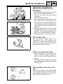
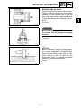
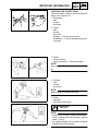


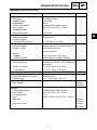
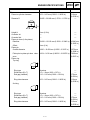


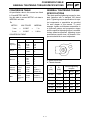

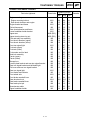
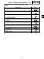
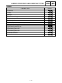


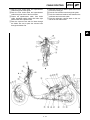
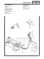

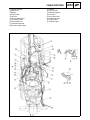
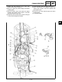

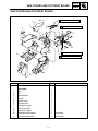

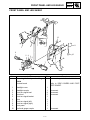
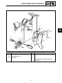
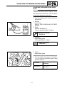


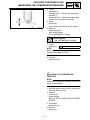


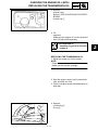

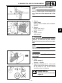
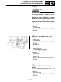
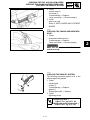

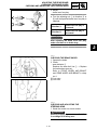
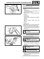
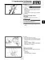

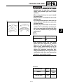

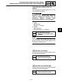

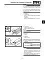


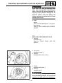
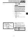
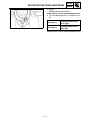
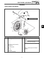

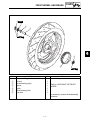


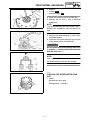
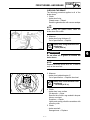
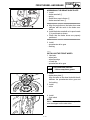


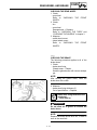
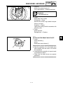
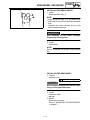
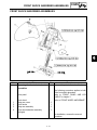
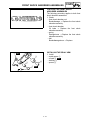

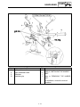

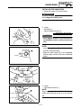

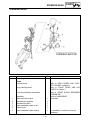
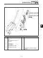

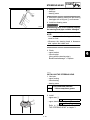
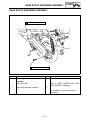

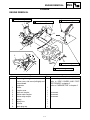

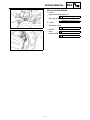
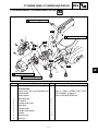
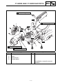
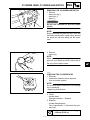
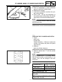

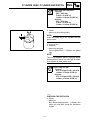
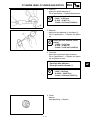
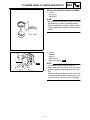
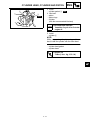

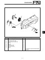
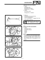


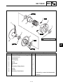
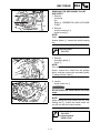
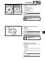
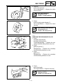

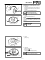

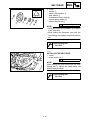

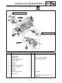
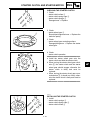
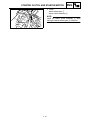

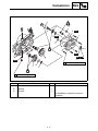

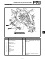

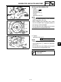
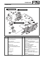
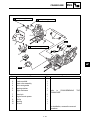
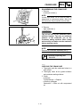
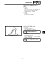
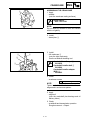
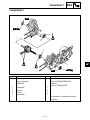
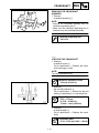


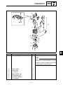
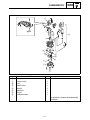
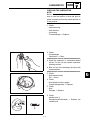
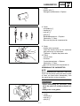
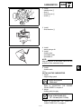
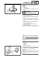
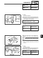
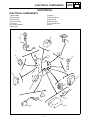
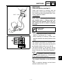


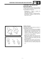


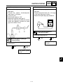

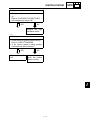
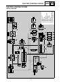

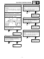
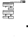


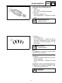
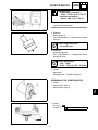
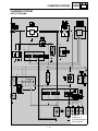


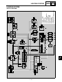


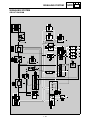
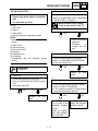
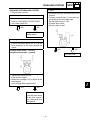
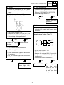

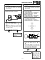


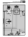


![Manuale Officina [ ITA ] Yamaha R1 2002-2003](http://vs1.manualzilla.com/store/data/006110674_1-52d32bbc9127defc0419b49b1226ec2b-150x150.png)