1
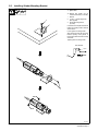
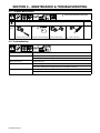
OM-230 915B
2007−03
Processes
TIG (GTAW) Welding
Description
Tungsten Grinder
MTG Plus
Tungsten Grinder
File: TIG (GTAW)
Visit our website at
www.MillerWelds.com
From Miller to You
Thank you and congratulations on choosing Miller. Now you can get
the job done and get it done right. We know you don’t have time to do
it any other way.
That’s why when Niels Miller first started building arc welders in 1929,
he made sure his products offered long-lasting value and superior
quality. Like you, his customers couldn’t afford anything less. Miller
products had to be more than the best they could be. They had to be the
best you could buy.
Today, the people that build and sell Miller products continue the
tradition. They’re just as committed to providing equipment and service
that meets the high standards of quality and value established in 1929.
This Owner’s Manual is designed to help you get the most out of your
Miller products. Please take time to read the Safety precautions. They
will help you protect yourself against potential hazards on the worksite.
We’ve made installation and operation quick
and easy. With Miller you can count on years
of reliable service with proper maintenance.
And if for some reason the unit needs repair,
there’s a Troubleshooting section that will
help you figure out what the problem is. The
Miller is the first welding parts list will then help you to decide the
equipment manufacturer in exact part you may need to fix the problem.
the U.S.A. to be registered to
the ISO 9001:2000 Quality Warranty and service information for your
System Standard.
particular model are also provided.
Miller Electric manufactures a full line
of welders and welding related equipment.
For information on other quality Miller
products, contact your local Miller distributor to receive the latest full
line catalog or individual specification sheets. To locate your nearest
distributor or service agency call 1-800-4-A-Miller, or visit us at
www.MillerWelds.com on the web.
Mil_Thank 2005−04
Working as hard as you do
− every power source from
Miller is backed by the most
hassle-free warranty in the
business.
TABLE OF CONTENTS
SECTION 1 − SAFETY PRECAUTIONS - READ BEFORE USING . . . . . . . . . . . . . . . . . . . . . . . . . . . . . . . . . . .
1-1. Symbol Usage . . . . . . . . . . . . . . . . . . . . . . . . . . . . . . . . . . . . . . . . . . . . . . . . . . . . . . . . . . . . . . . . . . . . . . . .
1-2. Tungsten Grinding Hazards . . . . . . . . . . . . . . . . . . . . . . . . . . . . . . . . . . . . . . . . . . . . . . . . . . . . . . . . . . . . .
1-3. California Proposition 65 Warnings . . . . . . . . . . . . . . . . . . . . . . . . . . . . . . . . . . . . . . . . . . . . . . . . . . . . . . .
1-4. Principal Safety Standards . . . . . . . . . . . . . . . . . . . . . . . . . . . . . . . . . . . . . . . . . . . . . . . . . . . . . . . . . . . . .
SECTION 2 − DEFINITIONS . . . . . . . . . . . . . . . . . . . . . . . . . . . . . . . . . . . . . . . . . . . . . . . . . . . . . . . . . . . . . . . . . . .
2-1. Manufacturer’s Rating Label For CE Products . . . . . . . . . . . . . . . . . . . . . . . . . . . . . . . . . . . . . . . . . . . . .
2-2. Symbols And Definitions . . . . . . . . . . . . . . . . . . . . . . . . . . . . . . . . . . . . . . . . . . . . . . . . . . . . . . . . . . . . . . .
SECTION 3 − SPECIFICATIONS . . . . . . . . . . . . . . . . . . . . . . . . . . . . . . . . . . . . . . . . . . . . . . . . . . . . . . . . . . . . . . . .
3-1. Description . . . . . . . . . . . . . . . . . . . . . . . . . . . . . . . . . . . . . . . . . . . . . . . . . . . . . . . . . . . . . . . . . . . . . . . . . .
3-2. Included With Your Unit . . . . . . . . . . . . . . . . . . . . . . . . . . . . . . . . . . . . . . . . . . . . . . . . . . . . . . . . . . . . . . . .
3-3. Specifications . . . . . . . . . . . . . . . . . . . . . . . . . . . . . . . . . . . . . . . . . . . . . . . . . . . . . . . . . . . . . . . . . . . . . . . .
SECTION 4 − INSTALLATION . . . . . . . . . . . . . . . . . . . . . . . . . . . . . . . . . . . . . . . . . . . . . . . . . . . . . . . . . . . . . . . . . .
4-1. Connecting Input Power . . . . . . . . . . . . . . . . . . . . . . . . . . . . . . . . . . . . . . . . . . . . . . . . . . . . . . . . . . . . . . . .
4-2. Connecting Grinder To Exhaust (Vacuum) Hose . . . . . . . . . . . . . . . . . . . . . . . . . . . . . . . . . . . . . . . . . . . .
SECTION 5 − OPERATION . . . . . . . . . . . . . . . . . . . . . . . . . . . . . . . . . . . . . . . . . . . . . . . . . . . . . . . . . . . . . . . . . . . .
5-1. Grinder Components . . . . . . . . . . . . . . . . . . . . . . . . . . . . . . . . . . . . . . . . . . . . . . . . . . . . . . . . . . . . . . . . . .
5-2. Grinding And Cutting Electrodes . . . . . . . . . . . . . . . . . . . . . . . . . . . . . . . . . . . . . . . . . . . . . . . . . . . . . . . . .
5-3. Replacing Grinding Wheels . . . . . . . . . . . . . . . . . . . . . . . . . . . . . . . . . . . . . . . . . . . . . . . . . . . . . . . . . . . . .
5-4. Installing Optional Double-Decker Kit . . . . . . . . . . . . . . . . . . . . . . . . . . . . . . . . . . . . . . . . . . . . . . . . . . . . .
5-5. Installing Grinder Mounting Bracket . . . . . . . . . . . . . . . . . . . . . . . . . . . . . . . . . . . . . . . . . . . . . . . . . . . . . .
SECTION 6 − MAINTENANCE & TROUBLESHOOTING . . . . . . . . . . . . . . . . . . . . . . . . . . . . . . . . . . . . . . . . . . .
6-1. Routine Maintenance . . . . . . . . . . . . . . . . . . . . . . . . . . . . . . . . . . . . . . . . . . . . . . . . . . . . . . . . . . . . . . . . . .
6-2. Troubleshooting . . . . . . . . . . . . . . . . . . . . . . . . . . . . . . . . . . . . . . . . . . . . . . . . . . . . . . . . . . . . . . . . . . . . . .
SECTION 7 − PARTS LIST . . . . . . . . . . . . . . . . . . . . . . . . . . . . . . . . . . . . . . . . . . . . . . . . . . . . . . . . . . . . . . . . . . . . .
1
1
1
2
2
3
3
3
4
4
4
5
5
5
6
7
7
8
9
10
11
12
12
12
13
SECTION 1 − SAFETY PRECAUTIONS - READ BEFORE USING
Tung_Grind 9/06
Warning: Protect yourself and others from injury — read and follow these precautions.
1-1. Symbol Usage
Means Warning! Watch Out! There are possible hazards
with this procedure! The possible hazards are shown in
the adjoining symbols.
Marks a special safety message.
Means “Note”; not safety related.
This group of symbols means Warning! Watch Out! possible
ELECTRIC SHOCK, MOVING PARTS, and HOT PARTS hazards.
Consult symbols and related instructions below for necessary actions
to avoid the hazards.
1-2. Tungsten Grinding Hazards
The symbols shown below are used throughout this manual to
call attention to and identify possible hazards. When you see
the symbol, watch out, and follow the related instructions to
avoid the hazard. The safety information given below is only
a summary of the more complete safety information found in
the Safety Standards listed in Section 1-4. Read and follow all
Safety Standards.
Only qualified persons should install, operate, maintain, and
repair this unit.
GRINDING can cause FIRE OR EXPLOSION.
Do not grind where flying sparks can strike
flammable material.
Protect yourself and others from flying sparks
and hot metal.
Be alert that sparks and hot materials from grinding can easily go
through small cracks and openings to adjacent areas.
Watch for fire, and keep a fire extinguisher nearby.
During operation, keep everybody, especially children, away.
FLYING SPARKS can cause injury.
ELECTRIC SHOCK can kill.
Touching live electrical parts can cause fatal shocks
or severe burns. The input power circuit and
machine internal circuits are also live when power is
on. Incorrectly installed or improperly grounded
equipment is a hazard.
Do not touch live electrical parts.
Wear dry, hole-free insulating gloves and body protection.
Disconnect input power before installing or servicing this
equipment.
Properly install this equipment according to its Owner’s Manual
and national, state, and local codes.
Frequently inspect input power cord for damage or bare wiring −
replace cord immediately if damaged − bare wiring can kill.
Turn off all equipment when not in use.
Use only well-maintained equipment. Repair or replace damaged
parts at once. Maintain unit according to manual.
Wear a face shield to protect eyes and face.
Shape tungsten electrode only on grinder with proper
guards in a safe location wearing proper face, hand,
and body protection.
Sparks can cause fires — keep flammables away.
HOT PARTS can cause severe burns.
Do not touch hot parts bare handed.
Allow cooling period before touching parts.
To handle hot parts, use proper tools and/or
wear heavy, insulated welding gloves and
clothing to prevent burns.
OVERUSE can cause OVERHEATING
Allow cooling period; follow rated duty cycle.
Keep air holes free of dust; clean if necessary.
Keep all panels and covers securely in place.
READ INSTRUCTIONS.
GRINDING DUST can be hazardous.
Grinding produces dust. Breathing this dust can be
hazardous to your health.
Do not breathe the dust.
Use local exhaust (forced ventilation) to remove dust or wear an
approved respirator.
Grinding dust from thoriated electrodes contains low-level radioactive material. Consider using tungsten containing ceria,
lanthana, or yttria instead of thoria.
Properly dispose of grinder dust in an environmentally safe way.
Read and understand the Material Safety Data Sheets (MSDSs)
and the manufacturer’s instructions for metals and consumables.
Read Owner’s Manual before using or servicing unit.
Use only genuine Miller replacement parts.
MOVING PARTS can cause injury.
Keep away from moving parts.
Keep all doors, panels, covers, and guards
closed and securely in place.
Have only qualified persons remove doors,
panels, covers, or guards for maintenance as
necessary.
Reinstall doors, panels, covers, or guards
when maintenance is finished and before reconnecting input power.
OM-230 915 Page 1
1-3. California Proposition 65 Warnings
Welding or cutting equipment produces fumes or gases which
contain chemicals known to the State of California to cause
birth defects and, in some cases, cancer. (California Health &
Safety Code Section 25249.5 et seq.)
1-4. Principal Safety Standards
Safety in Welding, Cutting, and Allied Processes, ANSI Standard Z49.1,
from Global Engineering Documents (phone: 1-877-413-5184, website:
www.global.ihs.com).
Recommended Safe Practices for the Preparation for Welding and Cutting of Containers and Piping, American Welding Society Standard
AWS F4.1 from Global Engineering Documents (phone:
1-877-413-5184, website: www.global.ihs.com).
National Electrical Code, NFPA Standard 70, from National Fire Protection Association, P.O. Box 9101, 1 Battery March Park, Quincy, MA
02269−9101 (phone: 617−770−3000, website: www.nfpa.org).
Practice For Occupational And Educational Eye And Face Protection,
ANSI Standard Z87.1, from American National Standards Institute, 11
West 42nd Street, New York, NY 10036−8002 (phone: 212−642−4900,
website: www.ansi.org).
Standard for Fire Prevention During Welding, Cutting, and Other Hot
Work, NFPA Standard 51B, from National Fire Protection Association,
P.O. Box 9101, 1 Battery March Park, Quincy, MA 02269−9101 (phone:
617−770−3000,website: www.nfpa.org).
Safe Handling of Compressed Gases in Cylinders, CGA Pamphlet P-1,
from Compressed Gas Association, 1735 Jefferson Davis Highway,
Suite 1004, Arlington, VA 22202−4102 (phone: 703−412−0900, website: www.cganet.com).
OSHA, Occupational Safety and Health Standards for General Industry, Title 29, Code of Federal Regulations (CFR), Part 1910, Subpart Q,
and Part 1926, Subpart J, from U.S. Government Printing Office, Superintendent of Documents, P.O. Box 371954, Pittsburgh, PA 15250 (there
are 10 Regional Offices−−phone for Region 5, Chicago, is
312−353−2220,website: www.osha.gov).
Code for Safety in Welding and Cutting, CSA Standard W117.2, from
Canadian Standards Association, Standards Sales, 178 Rexdale
Boulevard, Rexdale, Ontario, Canada M9W 1R3 (phone:
800−463−6727 or in Toronto 416−747−4044, website: www.csa−international.org).
Pacemaker wearers consult your doctor before welding or going near
welding operations. If cleared by your doctor, then following the above
procedures is recommended.
OM-230 915 Page 2
About Pacemakers:
SECTION 2 − DEFINITIONS
2-1. Manufacturer’s Rating Label For CE Products
2-2. Symbols And Definitions
NOTE
Some symbols are found only on CE products.
Output
Alternating Current
Single Phase
Line Connection
A
Hz
Amperes
Hertz
V
Volts
Read Instructions
Notes
Work like a Pro!
Pros weld and cut
safely. Read the
safety rules at
the beginning
of this manual.
OM-230 915 Page 3
SECTION 3 − SPECIFICATIONS
3-1. Description
The MTG Plus cuts, grinds, and planes tungsten electrodes used in the TIG (GTAW) welding process. Additional features and benefits of this unit are:
•
Electrodes are sharpened to conform to recognized standards.
•
The replaceable grinding wheel is diamond-coated on both sides.
•
•
The grinding wheel has an offset edge for easy cutting − an industry exclusive!
•
The unit can be hand operated, or wall or table-mounted using the supplied mounting bracket.
The head assembly allows for different electrode angles and diameters.
Grinding the tungsten electrode produces dust and flying sparks which can cause injury and start fires. Use local exhaust (forced ventilation) at the grinder or wear an approved respirator.
Read MSDS for safety information. Consider using tungsten containing ceria, lanthana, or yttria instead of thoria. Grinding dust from
thoriated electrodes contains low-level radioactive material. Properly dispose of grinder dust in an environmentally safe way. Wear
proper face, hand, and body protection. Keep flammables away.
3-2. Included With Your Unit
1
2
3
2
3
4
5
MTG Plus Tungsten Grinder
With Diamond Grinding Wheel
Steel Carrying Case
Electrode Holder With
Clamping Collet
Torx Screwdriver
Mounting Bracket
4
1
5
804 716 / Ref 804 762
OM-230 915 Page 4
3-3. Specifications
Dimensions
Weight
Input Power
2.6 x 13.8 in
(65 x 250 mm)
3 lb (1.4 kg)
(w/Grinding Wheel)
Noise
Rating
Vibration
Level
Power-On Time
Cord
Length
Rotary
Speed
100%
9.8 ft
(3 m)
30,000
RPM
(U/min)
120 V AC
2.5 m/s2
83 dBa
(per EN23741)
(per EN28662, Part 1)
50/60 Hz
(500 watt
Rating)
Electrode
Material
Electrode Angles
Tungsten electrodes
alloyed with zirconium,
lanthanum, and cerium
15°
Consult
country-specific regulations for
electrodes containing
Thorium.
Electrode Diameters
0.04 in (1 mm)
1/16 in (1.6 mm)
18°
3/32 in (2.4 mm)
22.5°
1/8 in (3.2 mm)
30°
5/32 in (4 mm)
SECTION 4 − INSTALLATION
Operation
4-1. Connecting Input Power
1
Rating Label
2
Power Cord
3
120 Volt AC Plug
4
AC Receptacle
Connect plug to matching AC receptacle. See rating label for electrical specifications.
4
3
2
1
804 717
OM-230 915 Page 5
4-2. Connecting Grinder To Exhaust (Vacuum) Hose
Grinding the tungsten electrode produces dust and flying sparks which can cause
injury and start fires. Use local exhaust (forced ventilation) at the grinder or wear an
approved respirator.
2
1
Read MSDS for safety information. Consider using
tungsten containing ceria,
lanthana, or yttria instead of
thoria. Grinding dust from
thoriated electrodes contains low-level radioactive
material. Properly dispose
of grinder dust in an environmentally safe way. Wear
proper face, hand, and body
protection. Keep flammables
away.
1
2
Grinder
Exhaust (Vacuum) System
The grinding head is designed to
accept a 1−1/4 in (32 mm) exhaust
(vacuum) hose.
Connect the grinder to the exhaust
(vacuum) hose as shown.
The optional protective cover/
adapter can also be used to connect the exhaust (vacuum) hose to
the grinder.
804 811
Notes
WELD POSITION: FLAT
WELD JOINT
TYPES
HORIZONTAL
BUTT
1G
VERTICAL
BUTT
2G
FILLET
Ref. AWS/ANSI D1.1
OM-230 915 Page 6
T−JOINT
1F
BUTT
4G
BUTT
3G
T−JOINT
2F
GROOVE
OVERHEAD
T−JOINT
4F
T−JOINT
3F
Ref. 804 248-A
SECTION 5 − OPERATION
Operation
5-1. Grinder Components
1
2
3
4
5
6
7
8
On/Off Switch
Identification Label
Grinding Head
Tungsten Sharpening Angle
Tungsten Sharpening
Diameters
Tungsten Sharpening Holes
Tungsten Surface Grinding
Holes
Tungsten Cutting Slot
1
2
6
5
3
4
8
7
804 718
OM-230 915 Page 7
5-2. Grinding And Cutting Electrodes
Grinding the tungsten electrode
produces dust and flying sparks
which can cause injury and start
fires. Use local exhaust (forced
ventilation) at the grinder or wear
an approved respirator.
Sharpening Electrode
Read MSDS for safety information. Consider using tungsten
containing ceria, lanthana, or yttria instead of thoria. Grinding
dust from thoriated electrodes
contains low-level radioactive
material. Properly dispose of
grinder dust in an environmentally safe way. Wear proper face,
hand, and body protection. Keep
flammables away.
Do not exert excessive pressure on
the grinding wheel or the life of the
wheel will be shortened.
Use
a rough grinding wheel to
sharpen large electrodes.
1
Wait until grinding wheel stops before restarting grinder.
Surface Grinding Electrode
1
Tungsten Electrode
To Sharpen Electrode:
Determine diameter of electrode and
desired sharpening angle.
Turn on grinder. Insert electrode in corresponding hole in grinder.
Slowly turn the electrode until tip is
sharpened evenly. If the electrode is not
turned the tip will be flat ground to the
selected angle.
To Surface Grind Electrode:
1
Determine diameter of electrode.
Turn on grinder. Insert electrode in corresponding hole at front of grinding
head. Grind the electrode tip until
square.
To Cut Electrode To Length:
(For Orbital Or Manual Welding):
2
Cutting Slot
Turn on grinder. Insert electrode in cutting slot and turn electrode slowly until
cut.
Cutting Electrode To Length
An optional
cutting device is available for larger electrodes. See Section 7.
Turn grinder off.
2
1
804 719
OM-230 915 Page 8
5-3. Replacing Grinding Wheels
Turn off grinder and disconnect
power cord.
1
2
3
4
5
6
Head Screw
Head
Head Nut
1/8 in (3 mm) rod
Grinding Wheel
Grinding Wheel Screw
Use Torx screwdriver to remove head
screw. Remove head. Do not remove
head nut.
Slide rod through cross hole and motor
shaft to prevent rotation of the grinding
wheel.
Remove grinding wheel screw. Remove
grinding wheel. Reverse or replace
grinding wheel.
2
To ensure correct installation, align
grinding wheel pilot hole with locator pin on shaft.
Reinstall grinding wheel screw and
washer, head, and head screw. Remove rod.
3
1
4
5
6
Tools Needed:
Torx
1/8 in (3 mm) Diameter Rod
804 720
OM-230 915 Page 9
5-4. Installing Optional Double-Decker Kit
Tools Needed:
Torx
2
1/8 in (3 mm) Diameter Rod
3
1
4
5
7
6
2
8
6
9
10
804 720 / 804 721
Turn off grinder and disconnect
power cord.
7
8
Items 7 − 10 are included in the kit.
9 Additional Grinding Head
10 Additional Head Screw (M4 x 34)
Screw shaft extension in shaft and tighten
with Torx screwdriver.
Use Torx screwdriver to remove original
head screw. Remove original head. Do not
remove head nut.
Reinstall original grinding head.
1
2
3
4
5
6
Original Head Screw (M4 x 15)
Original Grinding Head
Head Nut
1/8 in (3 mm) Rod
Standard Grinding Wheel
Grinding Wheel Screw
OM-230 915 Page 10
Shaft Extension
Rough Grinding Wheel
Slide rod through cross hole and motor
shaft to prevent rotation of the grinding
wheel.
Remove grinding wheel screw. Do not remove standard grinding wheel.
Install rough grinding wheel and secure with
grinding wheel screw.
Install new grinding head and head screw.
Remove rod.
5-5. Installing Grinder Mounting Bracket
Turn off grinder and disconnect
power cord.
Bracket
and grinder can be
mounted horizontally or vertically.
1
2
2
3
1
Bracket
1/4−20 x 1−/2 Mounting Screw
(Not Supplied)
Grinder Mounting Screws
(w/Collar)
Use bracket as a template to mark hole
location on mounting surface. Drill hole
where marked.
Loosen grinder mounting screws.
Align mounting screws with grooves in
bracket opening. Insert grinder in
bracket and rotate until switch is easily
accessible.
Tighten grinder mounting screws.
Tools Needed:
1/4 in
Torx
3
804 762
OM-230 915 Page 11
SECTION 6 − MAINTENANCE & TROUBLESHOOTING
6-1. Routine Maintenance
Disconnect power before maintaining.
= Check
= Clean
Reference
Every
8
Hours
Section 5-1
Grinder Head Is Secure
Power Cord For Damage Grinder Head Holes
Inside Of Housing
6-2. Troubleshooting
Trouble
Motor does not run.
Remedy
Have Factory Authorized Service Agent check power cable, and replace if necessary.
Have Factory Authorized Service Agent check motor, and replace if necessary.
Grinder head is loose.
Tighten head screw.
Grinding wheel does not turn.
Tighten grinding wheel screw.
Have Factory Authorized Service Agent check motor, and replace if necessary.
Grinding wheel wobbles.
Tighten grinding wheel screw.
Replace grinding wheel.
OM-230 915 Page 12
SECTION 7 − PARTS LIST
Hardware is common and
not available unless listed.
1
2
3
4
5
6
804 722
Figure 7-1. Complete Assembly
Item
No.
Dia.
Mkgs.
Part
No.
Description
Quantity
Figure 7-1. Complete Assembly
. . . 1 . . . . . . . . . . . . 232 143 . .
... 2 .......................
. . . . . . . . . . . . . . . . . . 232 144 . .
. . . 3 . . . . . . . . . . . . 232 145 . .
. . . 4 . . . . . . . . . . . . 232 146 . .
. . . 5 . . . . . . . . . . . . 232 147 . .
. . . 6 . . . . . . . . . . . . 232 148 . .
Motor, Electric 120 V, 50/60 Hz (Includes Flange) . . . . . . . . . . . . . . . . . . . . .
Label, Warning . . . . . . . . . . . . . . . . . . . . . . . . . . . . . . . . . . . . . . . . . . . . . . . . . . .
Brush, Carbon . . . . . . . . . . . . . . . . . . . . . . . . . . . . . . . . . . . . . . . . . . . . . . . . . . . .
Wheel, Grinding (Standard) . . . . . . . . . . . . . . . . . . . . . . . . . . . . . . . . . . . . . . . . .
Screw, Grinding Wheel M4 x 6 . . . . . . . . . . . . . . . . . . . . . . . . . . . . . . . . . . . . . .
Head, Grinding . . . . . . . . . . . . . . . . . . . . . . . . . . . . . . . . . . . . . . . . . . . . . . . . . . .
Screw. Head w/Collar M4 x 15 (Includes Head Nut) . . . . . . . . . . . . . . . . . . . .
1
1
2
1
1
1
2
To maintain the factory original performance of your equipment, use only Manufacturer’s Suggested
Replacement Parts. Model and serial number required when ordering parts from your local distributor.
OM-230 915 Page 13
Item
No.
Dia.
Mkgs.
Part
No.
Description
Quantity
Accessories
. . . . . . . . . . . . . . . . . . 232 149 . . Wheel, Grinding Rough . . . . . . . . . . . . . . . . . . . . . . . . . . . . . . . . . . . . . . . . . . 1
. . . . . . . . . . . . . . . . . . 232 150 . . Electrode Holder (Without Clamping Collets) . . . . . . . . . . . . . . . . . . . . . . 1
. . . . . . . . . . . . . . . . . . 232 151 . . Clamping Collet (For Clamping Electrode In Holder) . . . . . . . . . . . . . . . . 1
1/16 − 1/8 in. (1.6 mm − 3.2 mm)
. . . . . . . . . . . . . . . . . . 232 152 . . Wall/Table/Vice Mounting Plate (Includes Two Head Screws) . . . . . . . . 1
. . . . . . . . . . . . . . . . . . 232 153 . . Protective Cover (Protects Grinder Head) . . . . . . . . . . . . . . . . . . . . . . . . . . 1
..................
..................
..................
..................
..................
232 154
232 147
232 149
232 155
232 156
. . Double-Decker Kit (Consists Of)
. . . Head, Grinding . . . . . . . . . . . . . . . . . . . . . . . . . . . . . . . . . . . . . . . . . . . . . . . . . .
. . . Wheel, Grinding (Rough) . . . . . . . . . . . . . . . . . . . . . . . . . . . . . . . . . . . . . . . . .
. . . Screw, Head w/Collar M4 x 34 . . . . . . . . . . . . . . . . . . . . . . . . . . . . . . . . . . . .
. . . Extension, Shaft . . . . . . . . . . . . . . . . . . . . . . . . . . . . . . . . . . . . . . . . . . . . . . . .
1
1
1
1
To maintain the factory original performance of your equipment, use only Manufacturer’s Suggested
Replacement Parts. Model and serial number drequired when ordering parts from your local distributor.
OM-230 915 Page 14
Effective January 1, 2007
(Equipment with a serial number preface of “LH” or newer)
Warranty Questions?
Call
1-800-4-A-MILLER
for your local
Miller distributor.
Your distributor also gives
you ...
Service
You always get the fast,
reliable response you
need. Most replacement
parts can be in your
hands in 24 hours.
Support
Need fast answers to the
tough welding questions?
Contact your distributor.
The expertise of the
distributor and Miller is
there to help you, every
step of the way.
This limited warranty supersedes all previous Miller warranties and is exclusive with no other
guarantees or warranties expressed or implied.
LIMITED WARRANTY − Subject to the terms and conditions
* Induction Heating Coils and Blankets, Cables, and
below, Miller Electric Mfg. Co., Appleton, Wisconsin, warrants to
Non-Electronic Controls
its original retail purchaser that new Miller equipment sold after
* APT & SAF Model Plasma Cutting Torches
the effective date of this limited warranty is free of defects in
* Remote Controls
material and workmanship at the time it is shipped by Miller. THIS
WARRANTY IS EXPRESSLY IN LIEU OF ALL OTHER
* Accessory (Kits)
WARRANTIES, EXPRESS OR IMPLIED, INCLUDING THE
* Replacement Parts (No labor)
WARRANTIES OF MERCHANTABILITY AND FITNESS.
* Spoolmate Spoolguns
Within the warranty periods listed below, Miller will repair or
* Canvas Covers
replace any warranted parts or components that fail due to such
defects in material or workmanship. Miller must be notified in
writing within thirty (30) days of such defect or failure, at which
time Miller will provide instructions on the warranty claim
procedures to be followed.
Miller shall honor warranty claims on warranted equipment listed
below in the event of such a failure within the warranty time
periods. All warranty time periods start on the delivery date of the
equipment to the original end-user purchaser, and not to exceed
one year after the equipment is shipped to a North American
distributor or eighteen months after the equipment is shipped to
an International distributor.
1.
5 Years Parts — 3 Years Labor
2.
3 Years — Parts and Labor
*
*
*
*
*
*
*
*
*
3.
Original main power rectifiers
Transformer/Rectifier Power Sources
Plasma Arc Cutting Power Sources
Process Controllers
Semi-Automatic and Automatic Wire Feeders
Inverter Power Sources (Unless Otherwise Stated)
Water Coolant Systems (Integrated)
Intellitig
Engine Driven Welding Generators
(NOTE: Engines are warranted separately by the
engine manufacturer.)
1 Year — Parts and Labor Unless Specified
*
*
*
*
*
*
*
*
*
*
*
*
*
*
*
*
*
*
*
Motor Driven Guns (w/exception of Spoolmate
Spoolguns)
Positioners and Controllers
Automatic Motion Devices
RFCS Foot Controls
Induction Heating Power Sources, Coolers, and
Electronic
Controls/Recorders
Water Coolant Systems (Non-Integrated)
Flowgauge and Flowmeter Regulators (No Labor)
HF Units
Grids
Spot Welders
Load Banks
Arc Stud Power Sources & Arc Stud Guns
Racks
Running Gear/Trailers
Plasma Cutting Torches (except APT & SAF
Models)
Field Options
(NOTE: Field options are covered under True Blue®
for the remaining warranty period of the product they
are installed in, or for a minimum of one year —
whichever is greater.)
Bernard-Branded Mig Guns (No Labor)
Weldcraft-Branded TIG Torches (No Labor)
Subarc Wire Drive Assemblies
4.
6 Months — Batteries
5.
90 Days — Parts
*
MIG Guns/TIG Torches and Subarc (SAW) Guns
Miller’s True Blue® Limited Warranty shall not apply to:
1.
Consumable components; such as contact tips,
cutting nozzles, contactors, brushes, slip rings, relays
or parts that fail due to normal wear. (Exception:
brushes, slip rings, and relays are covered on Bobcat,
Trailblazer, and Legend models.)
2.
Items furnished by Miller, but manufactured by others, such
as engines or trade accessories. These items are covered
by the manufacturer’s warranty, if any.
3.
Equipment that has been modified by any party other than
Miller, or equipment that has been improperly installed,
improperly operated or misused based upon industry
standards, or equipment which has not had reasonable and
necessary maintenance, or equipment which has been
used for operation outside of the specifications for the
equipment.
MILLER PRODUCTS ARE INTENDED FOR PURCHASE AND
USE BY COMMERCIAL/INDUSTRIAL USERS AND PERSONS
TRAINED AND EXPERIENCED IN THE USE AND
MAINTENANCE OF WELDING EQUIPMENT.
In the event of a warranty claim covered by this warranty, the
exclusive remedies shall be, at Miller’s option: (1) repair; or (2)
replacement; or, where authorized in writing by Miller in
appropriate cases, (3) the reasonable cost of repair or
replacement at an authorized Miller service station; or (4)
payment of or credit for the purchase price (less reasonable
depreciation based upon actual use) upon return of the goods at
customer’s risk and expense. Miller’s option of repair or
replacement will be F.O.B., Factory at Appleton, Wisconsin, or
F.O.B. at a Miller authorized service facility as determined by
Miller. Therefore no compensation or reimbursement for
transportation costs of any kind will be allowed.
TO THE EXTENT PERMITTED BY LAW, THE REMEDIES
PROVIDED HEREIN ARE THE SOLE AND EXCLUSIVE
REMEDIES. IN NO EVENT SHALL MILLER BE LIABLE FOR
DIRECT,
INDIRECT,
SPECIAL,
INCIDENTAL
OR
CONSEQUENTIAL DAMAGES (INCLUDING LOSS OF
PROFIT), WHETHER BASED ON CONTRACT, TORT OR ANY
OTHER LEGAL THEORY.
ANY EXPRESS WARRANTY NOT PROVIDED HEREIN AND
ANY
IMPLIED
WARRANTY,
GUARANTY
OR
REPRESENTATION AS TO PERFORMANCE, AND ANY
REMEDY FOR BREACH OF CONTRACT TORT OR ANY
OTHER LEGAL THEORY WHICH, BUT FOR THIS
PROVISION, MIGHT ARISE BY IMPLICATION, OPERATION
OF LAW, CUSTOM OF TRADE OR COURSE OF DEALING,
INCLUDING
ANY
IMPLIED
WARRANTY
OF
MERCHANTABILITY OR FITNESS FOR PARTICULAR
PURPOSE, WITH RESPECT TO ANY AND ALL EQUIPMENT
FURNISHED BY MILLER IS EXCLUDED AND DISCLAIMED
BY MILLER.
Some states in the U.S.A. do not allow limitations of how long an
implied warranty lasts, or the exclusion of incidental, indirect,
special or consequential damages, so the above limitation or
exclusion may not apply to you. This warranty provides specific
legal rights, and other rights may be available, but may vary from
state to state.
In Canada, legislation in some provinces provides for certain
additional warranties or remedies other than as stated herein,
and to the extent that they may not be waived, the limitations and
exclusions set out above may not apply. This Limited Warranty
provides specific legal rights, and other rights may be available,
but may vary from province to province.
miller_warr 2007−01
Owner’s Record
Please complete and retain with your personal records.
Model Name
Serial/Style Number
Purchase Date
(Date which equipment was delivered to original customer.)
Distributor
Address
City
State
Zip
For Service
Contact a DISTRIBUTOR or SERVICE AGENCY near you.
Always provide Model Name and Serial/Style Number.
Contact your Distributor for:
Welding Supplies and Consumables
Options and Accessories
Personal Safety Equipment
Service and Repair
Miller Electric Mfg. Co.
Replacement Parts
Training (Schools, Videos, Books)
Technical Manuals (Servicing Information
and Parts)
Circuit Diagrams
Welding Process Handbooks
To locate a Distributor or Service Agency visit
www.millerwelds.com or call 1-800-4-A-Miller
Contact the Delivering Carrier to:
File a claim for loss or damage during
shipment.
For assistance in filing or settling claims, contact
your distributor and/or equipment manufacturer’s
Transportation Department.
PRINTED IN USA
© 2007 Miller Electric Mfg. Co. 2007−01
An Illinois Tool Works Company
1635 West Spencer Street
Appleton, WI 54914 USA
International Headquarters−USA
USA Phone: 920-735-4505 Auto-Attended
USA & Canada FAX: 920-735-4134
International FAX: 920-735-4125
European Headquarters −
United Kingdom
Phone: 44 (0) 1204-593493
FAX: 44 (0) 1204-598066
www.MillerWelds.com