1
90-MM6900
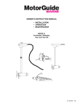
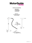
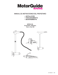
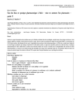
This MotorGuide Electric Motor, assembled of U.S.A. and foreign components by MotorGuide, 835
W. 41st St., Tulsa, OK, USA, complies with requirements of Directives 89/392/EEC and
89/336/EEC, 92/31/EEC, and 93/68 EEC as amended.
Dave Rowland
MotorGuide Business Unit Manager
MotorGuide
835 W. 41st Street, Tulsa, OK,
USA
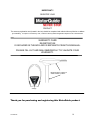
IMPORTANT!!
At MotorGuide, we’ve taken all the victories,
failures, blood, sweat, tears, hours, days and
years to heart and built what are possibly the
best performing, most reliable trolling motors
ever.
It’s a result of re-engineering from top to
bottom, from our new digital modules, to new
switches and props. Why? The reason is
simple. To give you the advantage—and, in
this case it’s a digital advantage.
Because at MotorGuide, we believe there are
some things you should Never Stop doing,
NEVER STOP LEARNING,
NEVER STOP IMPROVING,
AND NEVER EVER STOP FISHING.
REGISTER YOUR
PRODUCT
The warranty registration card (located
inside the box) should be completed and
mailed to MotorGuide to validate your
warranty.
WARRANTY CARD
REGISTRATION
IS INCLUDED IN THE BOX AND IS
SEPARATE FROM THIS MANUAL.
PLEASE FILL OUT IMMEDIATELY
AND MAIL TO VALIDATE YOUR
WARRANTY.
Thank you for purchasing this MotorGuide product.
90-MM6900
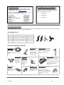
TABLE OF CONTENTS
General Information
Safety DO’s and DON’Ts ....................................2
How to use this Manual ......................................2
Specifications......................................................2
Wiring & Battery Information
Wire and Cable Routing......................................3
Establishing a Common Ground .......................3
Recommendations ..............................................3
12 Volt Battery Hook-up .....................................4
24 Volt Battery Hook Up .....................................4
36 Volt Battery Hook Up .....................................4
Mount Installations
Transom Mount Installation ...............................5
Twist Tiller Models ..................................5
Using Quick Stow ...................................5
Pontoon Mount Installation........................ 5
Bow Mount Installation............................... 6
Bow Mount Operation
Digital Steering Trolling Motors
Features and Operation......................................10
How to Operate the Digital Steer Motor ............10
Steering the Motor ..................................11
Controlling the Motor Prop......................11
Motor Set-Up .......................................................11
Stow Alignment Procedure .....................11
Programming Momentary Buttons ..........11
Center Alignment ....................................12
Center Alignment Procedure ..................12
Making Final Touches ........................................12
Hard Mounting the Foot Pedal ................12
Adjusting Foot Pedal Resistance ............13
Foot Pedal Calibration ............................13
Maintenance
Replacing the Propeller ......................................14
Tour Edition–Cable Tension Adjustment..........14
Customer Responsibilities.................................14
Battery ....................................................14
Freezing Temperature Storage...............14
Great White Saltwater Models ................14
Troubleshooting
Problems & Possible Causes / Solutions .........15
Installing the Motor into the Mount ...................7
Removing the Motor from the Mount ................7
Raising and Lowering the Trolling Motor..........7
Raising The Motor ..................................7
Lowering the Motor .................................7
Adjusting the Steering Tension
(Hand Operated Models).....................................7
Adjusting the Motor Depth .................................8
Trolling Motor Operation
Directional Indicator ...........................................8
Repair Parts and Service
For Repair Service ..............................................16
Replacement Parts & Ordering ..........................16
MotorGuide Accessories....................................16
Warranty Information
Two-Year Warranty .............................................17
Three-Year Warranty........................................... 17
Speed Control......................................................9
Five-Speed & Variable-Speed Motors.....9
Constant / Momentary /
High-Bypass ...........................................9
Twist Tiller Speed Control.......................9
Permanent Foot Pedal Mounting .......................9
90-MM6900
1
GENERAL INFORMATION
Please read and retain this manual. The information within
describes the proper procedures for safely installing,
operating and maintaining your motor.
The description and specifications contained herein were
in effect at the time this manual was approved for printing.
MotorGuide, whose policy is one of continual
improvement, reserves the right to discontinue models at
any time, to change specifications, designs, and methods
of procedure without notice and without incurring
obligation.
Safety and operating information that is practiced along
with good common sense can help prevent personal injury
and product damage.
! WARNING
DIGITAL MOTORS:
If the motor automatically throttles back, it
indicates something may be wrong with the motor
and it should be taken in for service.
! WARNING
DIGITAL MOTORS:
A slight voltage drain occurs when the trolling
motor is continually connected to the battery for
extended periods of time. To prevent battery drain
when not in use fro an extended period,
disconnect the trolling motor from the power
source.
!
Do secure loose items on your boat before traveling
at high speeds across the water.
How to Use This Manual
Review the following information carefully. These
notices will alert you to potential dangers and
important information.
The observance of WARNINGS and CAUTIONS
alone does not eliminate the possibility of personal
injury or product damage. Your close attention to the
performance of recommended service procedures
and the practice of responsible personal safety are
major accident prevention measures.
! WARNING
Failure to follow a safety WARNING can result in
bodily injury.
CAUTION
Failure to observe CAUTION instructions can result in
failure or damage to the product or equipment.
INFORMATION
Signifies important information about your trolling
motor.
NOTE
Signifies a statement calling attention to general
information about your trolling motor.
CAUTION
Disconnect the trolling motor from the battery(s)
before charging.
Safety DO’s and DON’Ts
!
Do not allow children to operate the trolling motor
without adult supervision.
!
Do not modify the unit in any way or add accessories
other than approved MotorGuide accessories.
!
!
!
Do not power-wash your trolling motor.
Do disconnect the power from the motor when
replacing the prop, removing debris around the prop,
charging batteries, putting your boat on a trailer or
when the motor is not in use.
Do make sure the foot pedal is secured and the motor
is securely locked into the stowed position when using
a gasoline motor to move to another location, or when
putting your boat on a trailer.
90-MM6900
Specifications
Model
Volts
Kwatts
Kilos
T25
T30
30
36
40
46
54
71
54 V
70 V
71 V
82 V
109 V
54 V DS
82 V DS
109 V DS
12
12
12
12
12
12
12
24
12
24
24
24
36
12
24
36
0.20
0.20
0.20
0.25
0.25
0.28
0.34
0.48
0.34
0.48
0.48
0.78
0.88
0.34
0.78
0.88
6.11
6.11
7.08
7.7
7.7
8.17
10.7
15.92
10.7
15.92
19.92
22.4
24.2
10.7
21.8
23.3
2
WIRING & BATTERY
Establishing a Common Ground
! WARNING
Batteries contain sulfuric acid which can cause
severe burns. Avoid contact with skin, eyes, and
clothing. The battery also produces hydrogen and
oxygen gasses when being charged. This
explosive gas is released through the battery
vents and may form an explosive atmosphere
around the battery for several hours after it has
been charged. Electrical arcing or flames can
ignite the gas and cause an explosion which may
shatter the battery and could cause blindness or
other serious personal and property damage.
Refer to your battery manufacturer’s guidelines for
charging instructions.
! WARNING
Be sure all switches are in the OFF position before
connecting the motor to the batteries. Electrical
arcing near the battery could ignite hydrogen gas
and cause the battery to explode.
! WARNING
MotorGuide recommends isolating the trolling motor
battery/batteries from the main engine battery.
Electrolysis Issues – Using the engine starting battery as
a source of power for any trolling motor may cause
electrolysis on metallic parts.
9
If you have followed the battery wiring and
installation instructions in this manual and your
boat continues to have electrolysis issues, you
will need to separate the trolling motor from any
other boat electronics.
9
Remove the engine starting battery from the
wiring configuration of the boat and isolate the
power circuit for your trolling motor.
•
Establish a Common Ground: Common ground
means the ground for the main engine accessories
and your trolling motor are connected to the same
negative ground terminal.
•
Not having a common ground can cause severe
corrosion or electrolysis. If left unchecked, damage
may be caused to your trolling motor and boat.
•
Establishing a common ground connection will allow
increased sensitivity and improve detail on a sonar
display.
Avoid serious injury or death from a possible fire
caused by a direct short; do not jump-start an
outboard motor using the trolling motor
battery/batteries.
Recommendations
Wire & Cable Routing
•
Route trolling motor wires on the opposite side of the
boat from other miscellaneous boat wiring (bow light
wireing, spot light wiring, etc.).
•
Transducer installation should be installed according
to the manufacturer’s specifications. To avoid
interference, cables should be routed separately from
the trolling motor power cables.
•
IMPORTANT: Do not route the transducer cable
down the trolling motor power cord or foot pedal
assembly cable. Route the transducer cable down
the arm of the mount, then into the bow console.
•
Sensitive electronics, depth finders in particular,
should be connected directly to the main engine
battery. If only a one battery system is used, then
connect with separate cables.
90-MM6900
•
Battery Type – The recommended battery is a 12volt Deep Cycle battery.
•
Circuit Protection – MotorGuide recommends
installing a 50 amp manual-reset circuit breaker in line
with the trolling motor positive leads within (1.8 m) 72
inches of the battery(s). To order a circuit breaker kit,
contact your local Service Dealer, request kit number
MM5870.
•
Wire Size – For optimum performance, MotorGuide
recommends the use of six (6) gauge (13 mm) wire if
extending existing wire beyond the standard battery
cable supplied with the product.
•
Bow Plugs – For temporary trolling motor
installations, MotorGuide recommends the use of a
quality plug designed for marine applications.
3
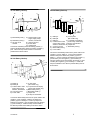
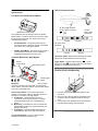
12 Volt Battery Hook-up
36 Volt Battery Hook-up
F
E
D
E
D
AA
G
H
F
G
I
B
J
A
C
L
K
B
K
C
A)
B)
C)
D)
Battery A
Battery B
Battery C
Positive lead to main
engine, bilge pumps,
aerators, accessories
E) Common ground
F) Black battery lead (-)
G) Power Cable
A) Black battery lead (-)
D) Positive lead to main
engine, bilge pumps,
B) Red battery lead (+)
aerators, accessories
C) 50 amp circuit
E) Common ground
breaker
F) Power cable
G) Jumper Wire
Connect the red battery lead to the battery positive (+)
post and the black battery lead to the battery negative (-)
post. Install a 50 amp circuit breaker in line with the
positive lead as shown above.
24 Volt Battery Hook-up
C
E
F
D
H
G
K
H) To foot pedal
(DS models only)
I) To optional sonar display
(sonar ready models only)
J) 50 amp circuit breaker
K) Jumper wire
L) Red battery lead (+)
Connect the black battery lead from the power cable to the
negative (-) post on battery A. Connect the red battery
lead from the power cable to the positive (+) post of
battery C. Connect a jumper wire between the positive (+)
post of battery A to the negative (-) post of battery B.
Connect another jumper wire between the positive (+) post
of battery B to negative (-) post of battery C. Install a 50
amp circuit breaker in line with the positive battery lead as
shown above.
K
A
I
J
B
A) Battery A
B) Battery B
C) Positive lead to main
engine bilge pumps,
aerators, accessories
D) Common ground
E) Power cable
J
F) To foot pedal
(DS models only)
G) To optional sonar display
(sonar ready models only)
H) Black battery lead (-)
I) Red battery leads (+)
J) Jumper wire
K) 50 amp circuit breaker
Connect the black battery lead from the power cable to the
negative (-) post on battery A and the red lead to the
positive (+) post on battery B. Connect a jumper wire
between the negative (-) post of battery B and the positive
(+) post of battery A. Install a 50 amp circuit breaker in
line with the positive lead to battery B as shown above.
90-MM6900
4
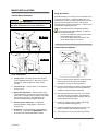
MOUNT INSTALLATIONS
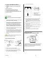
Using Quick Stow
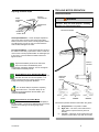
Transom Mount Installation
CAUTION
When adjusting the tilt on your motor, keep your fingers
clear of the area between the column and bracket.
2
3
09 Mount
4
Quick Stow allows you to stow your motor vertically as you
move from spot to spot. To lock the trolling motor in a
raised position, loosen the steering tension knob and raise
the motor the full length of the column, then push the
Quick Stow lever up into the lock position. Leave the lever
unlocked while operating the motor.
The Quick Stow device is designed to be stiff to
ensure extended life without slipping. To make the
operation of Quick Stow easier:
•
To loosen the Quick Stow, pull up on the column
while pushing down on the lever.
•
To secure the Quick Stow, push down on the
column while pulling up on the lever.
5
Pontoon Mount Installation
2
3
1
Mounting Holes
03 Mount
4
Twist Tiller Models
1)
Clamp screws – The clamp screws allow for easy
motor installation and removal. Mount your motor on
the transom, and then tighten the clamp screws
securely.
1)
Carefully select the area on the deck to install the
mount. Choose an area where the mount will provide
ample clearance for all of the motor positions
including the running and stowing positions.
2)
Tilt position pin – This pin allows you to adjust the
tilt of the motor.
2)
Place the mount base on the surface of the boat deck
where it is to be mounted; use the mount base as a
template to mark the location of the holes.
3)
Depth collar adjustment – The depth of the motor
can be adjusted up and down by loosening the depth
collar knob. The depth collar is located on the column
directly above the mount. After adjusting to the
position and depth desired, retighten the knob.
3)
Drill mounting holes with a (6.5 mm) ¼ inch drill bit
and clear the holes of any debris. Countersink the
holes (only on fiberglass boats) and again clear any
remaining debris from the holes.
4)
Steering tension adjustment – To adjust the
steering resistance, simply tighten or loosen the
tension knob.
4)
Install the 4 stainless steel mounting bolts through
each of the bracket mounting holes.
5)
5)
Quick Stow – Comes standard on some saltwater
models only. A Quick Stow kit (MGA052B6) can be
purchased from a MotorGuide Service Dealer.
Install the 4 stainless steel washers and nuts on the
bottom side of the deck and tighten securely.
6)
The trolling motor can now be placed in the mount.
90-MM6900
5
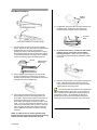
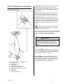
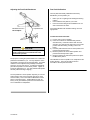
Bow Mount Installation
Rubber
Isolator
4)
07 Standard bow mount
IF applicable, insert the rubber mounting isolators into
the drilled holes. Position the wider side of the
isolator toward the outside of the mount bracket.
Tie Down
Strap
Heavy duty breakaway mount with springs
1)
Carefully select the area on the deck to install the
mount. Choose an area where the mount will provide
ample clearance for all of the motor positions
including the running and stowing positions. Ensure
the forward mounting screws are placed in a location
on the deck where there is enough room to install the
screws and washers without penetrating the hull.
Decket
2)
3)
5)
07 standard mount only – Position tie down strap
between the rear mount holes and the rubber
mounting isolators. Position the velcro side down
on the deck and the buckle facing toward the outside
of the boat.
6)
Place the mount bracket on the isolators and align the
holes. Install the two longer screws into the front
holes and the two shorter screws into the rear holes.
Tighten all of the mounting screws.
Standard Bow
Mount Only
Using a Phillips head screwdriver and the decket
screws provided in the hardware bag, secure the
decket to the mount base. (The decket for heavy duty
spring mounts can be installed last.)
Use the front mounting holes that go through the
plastic decket and the rear mounting holes on the
mount base. Place the mount base on the surface of
the boat deck where it is to be mounted; use the
mount base as a template to mark the location of the
holes. Use a very sharp drill bit to drill holes (5 cm) 2
inches into the boat deck. Drill a (13mm) ½ inch hole
when using the optional rubber isolators; otherwise
follow installation instructions for specific mounting
hardware.
It is important that the bracket lies even against the
isolators before bolting it to the deck. If the mount is not
even, it will bind as it is bolted down making it difficult or
impossible to unlatch. Once installed, the latch pins
should snap firmly into place and release easily with a
quick snap of the wrist and a light pull of the rope handle.
NOTE: A rubber spacer or washer should by used
between the base of the mount and the boat mounting
surface when the rubber isolators are not used.
90-MM6900
6
BOW MOUNT OPERATION
Raising the Motor
Installing the Motor into the Mount
Mount Rope
Handle
Bracket Door
Knob
1.
Turn the bracket door knob to the left to loosen and
open the bracket door.
2.
Place the motor column into the bracket and close the
door.
3.
Turn the bracket door knob to the right to tighten the
motor column in the bracket.
Removing the Motor from the Mount
Raise the motor out of the water by pulling on the mount
rope handle. Be careful not to let the weight of the motor
cause it to drop. Pull the rope handle until the motor can
be gently laid across the mount in the stow position.
Pressure is required to lock the motor into the stow
position. The trolling motor shaft is designed to bend
slightly, therefore apply pressure by pushing down on the
top housing and the shaft to lock the motor into stow.
Lowering the Motor
Bracket Door
Knob
1.
Turn the bracket door knob to the left to loosen and
open the bracket door.
2.
Remove the motor column from the bracket and close
the door.
Trolling Motor
& Mount in
Stow Position
To lower the motor into the water from the stow position;
lift the motor up by pulling the rope handle. Be careful not
to let the weight of the motor cause it to drop. Gently
lower the motor into the water.
Raising and Lowering the Trolling Motor
! WARNING
Your trolling motor should be raised and lowered
slowly by rope to avoid damage to your boat and
motor. To avoid pinching a toe or finger in the
mount, keep your hands and feet clear of the
mechanism when extending and retracting the
mount.
! WARNING
Ensure the motor is turned off before raising and
lowering the motor.
90-MM6900
Adjusting the Steering Tension (Hand Operated
Motors)
Steering
Tension Knob
Loosen the steering tension knob until the motor column
turns around freely. Tighten the steering tension knob to
secure the motor column in place.
7
TROLLING MOTOR OPERATION
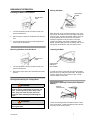
Adjusting the Motor Depth
Directional Indicator
Depth
Adjustment
Collar
Steering
Tension Knob
Bracket Door
Knob
! WARNING
Do not operate the trolling motor while it is out of
the water. Keep clear of the propeller. A rotating
propeller can cause personal injury.
Directional Indicator
Breakaway
Tension Knob
Hand Operated Motors – Loosen the depth adjustment
collar so the motor column moves freely up and down.
Raise or lower the motor column until the propeller blades
are submerged (15 to 30 cm) 6 to 12 inches below the
water surface and tighten the collar.
Foot Operated Motors - Loosen the bracket door knob so
the column moves freely up and down. Raise or lower the
motor column until the propeller blades are submerged (15
to 30 cm) 6 to 12 inches below the water surface and
tighten the door.
Motor in
Reverse
Adjust the breakaway knobs on the side of the
mount so the motor will breakaway when
encountering underwater obstacles. Do not over-tighten
or lubricate the breakaway handle.
Special Note for the 07 Standard Bow Mount:
It is normal for the bow arms to bend out slightly and
flex when the motor is in the stow position. The
mount is designed this way to keep pressure on the
trolling motor during rough water situations.
Directional
Indicator
Arrows
The Tie-Down Strap is required to completely
secure the motor. A Tie Down Strap can be
ordered through a MotorGuide Service Dealer, part
number # MGA029B6.
Special Note for the 16 Bow Mount
It is normal for the motor column to bend slightly in
the stow position. The mount is designed this way to keep
pressure on the trolling motor during rough water
situations.
bB
cC
REVERSE
REVERSE
The indicator provides directional information at a glance:
A)
B)
C)
90-MM6900
aA
CENTER
Straight Ahead – Foot pedal in middle
Right Turn – Toe down; motor steers boat to
right (continue to push all the way down for
reverse).
Left Turn – Heel down; motor steers boat to left
(continue to press all the way down for reverse).
8
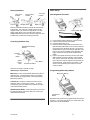
Twist Tiller Speed Control
Speed Control
Five-Speed and Variable Speed Motors
On /Off Toggle Switch &
Decal (Variable Speed Only)
Foot operated motors are either five-speed or variable
speed models. Control the speed of your motor by rolling
the speed control knob with your hand or foot until you
reach the desired speed.
9
Five-Speed Motor - The speed control knob on a
five-speed motor is numbered 1 through 5 and allows
you to select one of five preset speeds.
9
Variable Speed Motor - The speed control knob on a
variable speed motor allows you the capability of
variable speed selections from off to high.
On
Off
Forward
Five-speed Twist
Tiller Decal
Forward
Reverse
Reverse
Twist Tiller Handle - Rotate handle clockwise for forward
speeds and counterclockwise for reverse speeds.
Constant / Momentary / High-Bypass
Speed
Control Knob
Variable
Speed Twist
Tiller Decal
{
Speed Control Knob
Momentary Switch
Toggle Switch – Flip the Toggle switch to “
“ to turn
the motor on and ”{” to turn the motor off. This switch is
available on variable speed motors only.
Permanent Foot Pedal Mounting
Three
Position
Switch
A
B
C
On/Off Toggle
Switch
Momentary Switch – The Momentary Switch is located
on the top right side of the foot pedal. The Momentary
Switch works in conjunction with the Three-Position Switch
when it is in positions B and C.
Three-Position Switch - This three-position switch
provides you with three options for operating the motor:
constant on, momentary, and high-bypass.
A) Constant On - This allows the motor to run
continuously at the speed selected by the Speed
Control Knob without the use of the Momentary
switch.
B) Momentary - This allows the motor to activate with
the Momentary switch at the speed selected by the
Speed Control Knob.
C) High-Bypass - This will automatically deliver full
thrust when the Momentary switch is activated.
1)
2)
3)
Place the foot pedal in the desired location on the
boat deck.
Using a (3 mm) 7/64 inch drill bit, drill holes through
the holes in the foot pedal base and into the boat
deck.
Use four #8 x 2 inch stainless screws and screw the
foot pedal base securely to the boat deck.
On / Off Toggle Switch – Power on and off switch.
Available on variable speed motors only.
90-MM6900
9
DIGITAL STEERING TROLLING MOTORS
Features and Operation
Auto ON/OFF – Digital Steering units will turn ON when
deployed to the run position and OFF when stowed.
Press the Stow button to position the motor to land on the
bracket channel. Pull the motor back into the boat and
onto the bracket.
Motor Control – Microprocessor technology is used to
monitor motor performance and prevent damage. This
technology also prevents the motor from overheating.
Straight Line Steering – The foot pedal has a center
“Detent” position which is calibrated to drag the boat in a
straight line. Whenever you want the boat to be pulled in
a straight line, simply rock the pedal to the center “Detent”
position and press the Constant-On button on the foot
pedal.
This feature depends on proper calibration set by
the trolling motor operator. See the “Foot Pedal
Calibration” section in this manual.
How to Operate the Digital Steer Motor
! WARNING
Always disconnect the motor battery leads from
the power source when not in use. This will
prevent accidental starting of the motor which
could cause personal injury or damage to your
boat.
Turn on the Motor - Plug the motor into the power
h
j
source. Use the pull rope to lower the motor into the water
(known as the RUN position). The motor automatically
turns on when in the vertical run position.
Stow the Motor - Push and release the Stow button
once. The lower unit rotates to the stow position and all
pedal functions will cease. Set the motor on the bracket
(horizontal) and it will turn off. Unplug the motor when
moving the boat by trailer and when storing.
a)
b)
c)
d)
e)
f)
g)
h)
i)
j)
Heel/Toe action servo positioning pedal
Stow/Run button
Constant on button
Speed wheel
Selectable momentary buttons
Lighted directional pointer
Stainless steel outer tube and column
Lower unit
Battery cables
Foot pedal connection
90-MM6900
10
Steering the Motor
Heel Down
Position
Motor Set-Up
Straight Ahead
Left Turn
Toe Down
Position
Center Detent
Position
Stow Alignment Procedure
Right Turn
Rock the foot pedal heel down to steer left and toe down
to steer right. The motor has a steering range of 400
degrees to help you maneuver in tight spots. The 400
degree range allows you to point the motor past the
straight back position from either the left or right side. This
provides easy control when backing up the boat.
Stow Button
1)
2)
3)
4)
Controlling the Motor Prop
Selectable Momentary
Buttons
Constant
Off
Button
Speed
Control
Knob
5)
Stow Button
Constant On Button
There are two ways to operate the prop:
Momentary or Constant-On.
Momentary - Press and hold either Momentary button to
rotate the prop. The Momentary buttons on the Digital
Steer products are programmable. (See Programming
Momentary buttons.)
Stow Position Dial
Plug the motor battery cables into a power source.
Lower the motor into the Run position.
Push the Stow button once.
Rotate the Stow Position Dial until the lower unit is
approximately positioned to lie on the mount with the
prop facing to the outside of the boat. The mount is
designed for the prop to face the port (left) side of the
boat. If the mount is installed on the starboard side
(right) of the boat, the prop will be stowed facing
inside.
Pull the rope handle to lift the motor out of the water.
With the lower unit close to landing on the bracket
rails, use the dial to steer the lower unit to the left or
right. When the motor is aligned to land squarely on
the bracket rails, gently lower it into position. Push
down on the top housing and column to lock the
motor into place.
Programming Momentary Buttons
Momentary Buttons
Constant-On - Press the Constant-On button once to
rotate the prop in a continuous run mode. To cancel
Constant-On, press and release the Constant-On button
or the left Momentary button.
Speed Control Knob - Control the speed of your motor
by rolling the speed control knob with your foot until you
reach the desired speed.
Constant-On
Button
Both Momentary buttons are programmed at the factory to
be active. If you prefer having only one active button, the
other button can be deactivated.
90-MM6900
11
To Activate a Single Momentary Button:
1)
2)
3)
4)
Set the speed wheel at 0.
Press and hold the Momentary button you want to
activate.
Press and release the Constant-On button three
times.
Release all buttons.
b
To Activate Both Momentary Buttons:
1)
2)
3)
Press and hold both Momentary buttons.
Press and release the Constant button three times.
Release all buttons.
a
c
d
a)
b)
c)
d)
Needs adjustment to
right
Straight ahead.
Needs adjustment to left
Center Calibration Dial
Center Alignment
Keep the following in mind before alignment:
9
Pick a location protected from wind and free of heavy
weeds, timber and other obstructions.
9
Always keep your outboard straight and in the water.
Your outboard acts as a keel that, if turned to the
side, will bias your boat’s movement through the
water. Leaving your outboard in the water is also
important as it stabilizes the back of your boat while
steering, especially at moderate to high speeds.
9
9
Always securely tighten the bracket retention knob to
hold the shaft and head securely.
If Center (Straight Ahead) is not calibrated correctly,
you will not achieve the best steering performance.
This motor is equipped with Smart Steer software that
relies on Center (Straight Ahead) being calibrated
correctly.
5)
Pick an object directly in front of your boat (a large
tree, rock, dock, etc.). Push and release the
Constant-On button once. Ramp up your speed
wheel, watching how your boat moves toward the
object.
6)
Use the Center Calibration Dial to steer the boat
straight ahead.
7)
Adjust the dial until your boat moves in a straight line
for at least 10 seconds.
8)
Press and release the Constant-On button once to
stop the motor.
9)
This calibration may be repeated as needed.
Making Final Touches
Hard Mounting the Foot Pedal to the Deck
Remember, the Stow and Center settings can be
easily recalibrated as needed.
Center Alignment Procedure
Mounting Holes
Approximate
Center Detent
Position
Center Calibration Dial
1)
Lower the motor to the Run position.
2)
Place the foot pedal in the center detent position.
3)
Use the Center Calibration Dial to steer your lower
unit to approximately straight ahead.
90-MM6900
To permanently mount your foot pedal to the deck, use the
predrilled mounting holes on the left and right side of the
pedal base. The holes are designed to accommodate a
flat head #10 stainless steel screw.
12
Adjusting the Foot Pedal Resistance
Foot Pedal Calibration
The foot pedal was initially calibrated at the factory.
Recalibrate your foot pedal if you:
•
•
•
Ball Detent Screws –
Do Not Adjust
Adjustment Nut
Notice you are not getting a full 400-degree steering
rotation.
Have installed a new pedal on your motor.
Have moved the trolling motor installation from one
side of the boat to the other.
Foot pedal calibration will maximize steering control at
high speeds.
To Calibrate a New Foot Pedal:
1)
2)
CAUTION
Do not adjust ball detent screws. They are
factory adjusted to give maximum feel to the
pedal center position.
The purpose of setting the pedal resistance is to make the
pedal feel comfortable for you. You may adjust the clutch
mechanism to change how firm the pedal feels. The pedal
resistance can be adjusted using a Phillips screwdriver
and a (13 mm) 1/2 inch wrench. To make this adjustment,
place the foot pedal in the heel-down position. Tighten or
loosen the adjustment nut. Your foot pedal should operate
smoothly without binding or slipping.
3)
4)
5)
Put the motor in the run position.
Press the Constant-On and Momentary buttons
simultaneously. Hold both buttons down for three
seconds. (You will notice the motor turn to the center
position and start making a clicking noise in the
head.)
Push the pedal forward to the toe-down position and
press the Momentary button.
Move the pedal to the center detent position and
press the Momentary button again.
Move the pedal to the heel-down position and press
the Momentary button.
The calibration for the foot pedal is now complete and the
clicking will stop. The motor should now steer in
accordance with the pedal movement.
The foot pedal has a center position stop that you can feel
while rocking it from end to end (heel down to toe down
and visa versa). This is done with the Ball Detent screws
shown in the above figure. The Ball Detent screws are
factory set to give maximum pressure to this feature and
are not intended for readjustment.
90-MM6900
13
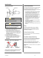
MAINTENANCE
Customer Responsibilities
Replacing the Propeller
Propeller Pin
Propeller
The motor/mount warranty does not cover items that have
been subjected to operator abuse or negligence. To
receive full value from the warranty, you must maintain the
motor/mount as instructed in this manual.
Propeller Nut
CAUTION
Make sure the motor is disconnected from the
battery before replacing the propeller.
CAUTION
Do not strike a bent prop pin with a hammer to
remove the pin. This may cause damage to the
armature, which is not covered by warranty.
MotorGuide recommends using pliers.
1)
2)
3)
4)
5)
While holding the propeller blade, use a prop wrench
to loosen and remove the propeller nut.
Pull the propeller straight off. If the prop is stuck,
grasp one blade with one hand and tap lightly on the
backside of the opposite blade with a rubber mallet. If
necessary, repeat the procedure on all blades until
the propeller comes off.
If the propeller pin is bent, replace it.
Align the new propeller with the propeller pin.
Reinstall the propeller nut and tighten securely with
your fingers. Tighten another 1/4 turn using a
MotorGuide Ninja Prop Wrench, part number
MGA050B6.
Tour Edition - Cable Tension Adjustment
Check behind the propeller after each use to ensure
weeds, fishing line or other debris are not wrapped
around the propeller or the propeller shaft.
Periodically lubricate all the pivot points with a nonaerosol lubricant. Never use an aerosol lubricant to
grease or oil any part of the unit. Many spray
lubricants contain harmful propellants that can cause
damage to various parts of your trolling motor.
Check the tightness of the battery lead connections.
Periodically inspect for loose or corroded wiring
connections.
Thoroughly rinse your trolling motor with freshwater
after each use in saltwater.
Periodically make a visual inspection for tightness of
all nuts, bolts and screws.
Before or after use, periodically check the prop nut for
tightness.
Battery
Recharge your batteries after each use. Follow the
battery manufacturer’s recommendations for battery
maintenance. Have your batteries tested annually to
ensure quality of operation.
Freezing Temperature Storage
Store your trolling motor where it will not be affected by
freezing temperatures.
Great White Saltwater Models Only
Corrosion on the metal components of the trolling motor
occurs when two or more metals that are dissimilar are
brought into electrical contact under water.
The use of a sacrificial anode causes all of the other
metals on the trolling motor to become the cathodes. The
anode will corrode and the trolling motor will not.
Maintenance: If excessive corrosion occurs, replace the
anode.
Underside of
Foot Pedal
Adjustment
Nuts
Adjustment Nut
Enlargement
Sacrificial Anode Kit
Part Number: MAR00204
Using a 7/16 wrench, tighten the cable tension by turning
the adjustment nuts counter-clockwise until the cable
tension reaches the optimal tightness.
90-MM6900
14
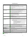
TROUBLESHOOTING
PROBLEM
POSSIBLE CAUSES AND/OR SOLUTIONS
•
•
•
•
Loss of power
•
Motor makes excessive noise or
vibrates excessively
•
•
•
•
•
•
Motor fails to run at any speed
•
•
•
•
•
•
The propeller may be fouled. Remove the propeller; clean or replace if necessary.
The battery connections may be corroded.
The battery may have low voltage. Recharge and test for a bad cell.
The wire gauge from the battery to the trolling motor may be insufficient. (Six-gauge
wire is recommended.)
A bad or faulty connection or pinched wire could exist in the boat wiring or trolling
motor wiring.
The permanent magnets may be cracked or chipped. The motor will whine or grind.
There may be water in the lower unit or oily residue inside the top housing.
The propeller may be fouled. Remove the propeller; clean or replace if necessary.
The propeller may be loose. Check to see if the propeller is secure.
The armature may be bent. Remove the propeller and set the motor at medium
speed. Turn the unit on and look for the shaft to wobble.
The magnets may be interfering with the armature. Turn the power is off. Turn the
prop by hand; it should turn freely with a slight magnetic drag.
The bearings or bushings may be worn out.
Check the trolling motor fuse/circuit breaker on the boat.
Check for loose or corroded connections.
Check the plug for a loose or bad connection.
Test the on/off, bypass and micro switches.
Make sure the power is off. Turn the prop by hand; it should turn freely with a slight
magnet drag.
There may be loose connections in the top housing.
The rotary switch may be bad.
The propeller may be fouled. Remove the propeller; clean or replace if necessary.
The speed coils in the lower unit may be burned.
Motor loses one or more speeds
•
•
•
•
Mount is hard to unlatch from
the run or stow position when
using pull rope
• Your bow mount is designed to easily release with a quick pull of the rope handle. If
it does not easily release, it is typically due to improper installation of the bracket.
o It is possible the bracket was not resting evenly on top of the rubber isolators
before it was tightened down.
o Once tightened, the bracket binds up causing the latch to function improperly.
o You can test this by loosening the screws slightly (start with the two
forward screws) and latching the bracket.
o You will usually find the problem area by alternately loosening each
screw until the bracket releases easily.
o The solution is to install shim washers (not provided) and then
retighten the screws.
• Apply general-purpose grease to the latch pins and clamp screws periodically.
Foot pedal is hard to turn
(Mechanical steer models)
•
•
•
•
Motor does not turn the full 400
degree rotation
(Digital models only)
Arrow backlight is off
(Digital models only)
• The foot pedal may need to be recalibrated. See page 13 in this manual for
calibration instructions.
Battery drains
(Variable-speed Digital models
only)
Motor automatically throttles back
(Variable speed models only)
INFORMATION
90-MM6900
Check to see if the column is bent and binding against outer tube.
The outer tube may be bent and binding against the column.
The bottom bushing or bearing may be out of alignment, broken or dirty.
The steering cable may be kinked; replace the steering cable.
• The arrow light turns off after 3 minutes of motor inactivity. If the light stays off,
press the momentary button to turn the light back on. If the light continues to stay
off, take your motor in fro service.
• A slight voltage drain will occur if your variable speed motor remains continually
connected to your battery. Install a power disconnect switch or disconnect the
trolling motor.
• Refer to your nearest Service Dealer for assistance with trolling motor repairs.
Refer to your nearest Service Dealer for assistance with trolling motor repairs.
15
REPLACEMENT PARTS AND ORDERING
FOR REPAIR SERVICE
Contact your nearest MotorGuide Service Dealer. See a
complete listing of Service Dealers in the US and Canada at
our MotorGuide web site: www.motorguide.com.
MotorGuide has established Service Dealers as Parts
Distributors throughout the United States and Canada.
Have the following information ready and contact the
nearest Service Dealer to order parts:
Call Mercury Marine Consumer Affairs to obtain the name
and location of the Service Dealer nearest you.
United States:
Australia Pacific:
Canada:
Europe, Africa & Middle East:
Japan:
Latin America:
Singapore:
1-920-929-5040
61-3-9791-5822
905-816-4751
32-87-323-211
81-53-423-2500
954-744-3500
65-6546-6160
•
Model Number
•
Serial Number
•
Part Number
MOTORGUIDE ACCESSORIES
Making It More Perfect. Who says you cannot make the best even better? MotorGuide® factory accessories let fishermen customize motors
to their own unique needs. In addition, every one is a perfect fit.
REPLACEMENT PROPS
Prop
Description
Number
#10
3" Ninja, 2 Blade Power Prop
MGA0476
#12
3.5" Ninja, 2 Blade Power Prop
MGA0495
#15
3.5" Machette, 3 Blade Metal
MGA087X6
#16
3.5" Machette III, 3 Blade
MGA089X1
ADDITIONAL HARDWARE ACCESORIES
16-Foot Pedal
Extension Cable
MFPEC16
Works with DS
Series, PTSv
Tracking and Great White DS Series
motors.
Tie Down Strap
MGA029B6
Prevents damage
to the boat and
motor when
running in rough
water conditions.
Weight Plate
MLP312315
Foot pedal weight
plate for
Freshwater Series
bow mount motors.
90-MM6900
Bounce Buster™ for
Gator Mount
MGA053B6
Prevents mount, motor,
and boat damage in
rough water conditions.
(For 20, 20.5, 23 and
23.5 Gator Mounts.)
Transom Motor
Mount Bracket
MGA067X3
Allows the use of
a transom motor
on the front of a
jon boat or canoe.
(Mount not
included.)
Bounce Buster™ II
MGA097B6
Prevents mount, motor, and boat
damage in rough water conditions.
(For 21 and 24 Gator Spring
Mounts.)
Removable Mount
MGA068X3 (07, 15, 16 mounts)
MGA092X1 (20.5, 21 mounts)
MGA093X1 (23, 23.5, 24 mounts)
Specially designed for fish-and-ski
and pontoon boats. Aluminum
construction. Adapts to most
trolling motors.
Ninja™ Prop Wench
MGA050B6
Comes complete with
spare prop nut and two
prop pins, allowing fast
prop changes.
Mounting Isolators
MGA015PB6 – Standard Mount
Absorbs shock and protects
electronics. Ideal for mounting all
marine accessories without having to
go under the deck. Four per
package.
16
MOTORGUIDE LIMITED TWO-YEAR WARRANTY
MOTORGUIDE LIMITED THREE-YEAR
WARRANTY
(KEEP YOUR ORIGINAL PURCHASE RECEIPT)
For recreational use customers, MotorGuide Freshwater Series
electric trolling motors are warranted to the original retail
1
purchaser to be free from defects in material and/or workmanship
for a period of two (2) years from the date of purchase. This
Limited Warranty begins on the date the product is first sold to a
retail purchaser or the date on which the product is first put into
2
service, whichever occurs first. Commercial users of these
products receive coverage for one (1) year from the date of first
retail sale. MotorGuide Accessories are covered by this Limited
Warranty for a coverage period of one (1) year from the date of
retail sale.
This warranty does not cover product damage due to abuse, i.e.,
bent columns, bent armature shafts, broken control cables, etc.,
accidents, modifications, misuse, excessive wear or damage
caused by an owner’s failure to provide reasonable and
necessary installation or care. Opening the lower unit (motor) by
anyone other than an authorized Service Dealer will void this
warranty. To obtain warranty service, the purchaser should
deliver or return the unit (postage prepaid and insured) to any
MotorGuide Authorized Service Dealer. Products returned by
mail should also be carefully packaged and include a note
describing the nature of the problem and/or service requested. A
copy of the proof of purchase or registration verification is
required with the return of the product for warranty consideration.
MotorGuide, at its discretion, will repair or replace items covered
under the terms of this warranty. Neither MotorGuide nor
MotorGuide Service Dealers are responsible for damages to
MotorGuide products due to repairs performed by anyone other
than an authorized MotorGuide Service Dealer. Neither
MotorGuide nor Mercury Marine is responsible for failure or
damage caused by improper installation, set-up, preparation, or
previous service or repair errors.
The product registration must be processed by MotorGuide within
ten (10) days from the date of purchase to validate your warranty.
MotorGuide products requiring service not covered under the
terms of this warranty may be repaired or replaced for a
reasonable fee. ALL INCIDENTAL AND\OR CONSEQUENTIAL
DAMAGES ARE EXCLUDED FROM THIS WARRANTY.
IMPLIED WARRANTIES ARE LIMITED TO THE LIFE OF THIS
WARRANTY. SOME STATES DO NOT ALLOW LIMITATIONS
ON HOW LONG AN IMPLIED WARRANTY LASTS OR THE
EXCLUSION OR LIMITATION OF INCIDENTAL OR
CONSEQUENTIAL DAMAGES, SO THE ABOVE LIMITATIONS
OR EXCLUSIONS MAY NOT APPLY TO YOU. THIS
WARRANTY GIVES YOU SPECIFIC LEGAL RIGHTS, AND YOU
MAY ALSO HAVE OTHER LEGAL RIGHTS WHICH MAY VARY
FROM STATE TO STATE.
For Your Records:
Model
Number__________________________________________
Serial Number___________________________________
(KEEP YOUR ORIGINAL PURCHASE RECEIPT)
For recreational use customers, MotorGuide Tour, Digital
Freshwater, Digital Steering, and Saltwater Series electric trolling
1
motors are warranted to the original retail purchaser to be free
from defects in material and/or workmanship for a period of three
(3) years from the date of purchase. This Limited Warranty
begins on the date the product is first sold to a retail purchaser or
the date on which the product is first put into service, whichever
2
occurs first. Commercial users of these products receive
coverage for one (1) year from the date of first retail sale.
MotorGuide Accessories are covered by this Limited Warranty for
a coverage period of one (1) year from the date of retail sale.
This warranty does not cover product damage due to abuse, i.e.,
bent columns, bent armature shafts, broken control cables, etc.,
accidents, modifications, misuse, excessive wear or damage
caused by an owner’s failure to provide reasonable and
necessary installation or care. Opening the lower unit (motor) by
anyone other than an authorized Service Dealer will void this
warranty. To obtain warranty service, the purchaser should
deliver or return the unit (postage prepaid and insured) to any
MotorGuide Authorized Service Dealer. Products returned by
mail should also be carefully packaged and include a note
describing the nature of the problem and/or service requested. A
copy of the proof of purchase or registration verification is
required with the return of the product for warranty consideration.
MotorGuide, at its discretion, will repair or replace items covered
under the terms of this warranty. Neither MotorGuide nor
MotorGuide Service Dealers are responsible for damages to
MotorGuide products due to repairs performed by anyone other
than an authorized MotorGuide Service Dealer. Neither
MotorGuide nor Mercury Marine is responsible for failure or
damage caused by improper installation, set-up, preparation, or
previous service or repair errors.
The product registration must be processed by MotorGuide within
ten (10) days from the date of purchase to validate your warranty.
MotorGuide products requiring service not covered under the
terms of this warranty may be repaired or replaced for a
reasonable fee. ALL INCIDENTAL AND\OR CONSEQUENTIAL
DAMAGES ARE EXCLUDED FROM THIS WARRANTY.
IMPLIED WARRANTIES ARE LIMITED TO THE LIFE OF THIS
WARRANTY. SOME STATES DO NOT ALLOW LIMITATIONS
ON HOW LONG AN IMPLIED WARRANTY LASTS OR THE
EXCLUSION OR LIMITATION OF INCIDENTAL OR
CONSEQUENTIAL DAMAGES, SO THE ABOVE LIMITATIONS
OR EXCLUSIONS MAY NOT APPLY TO YOU. THIS
WARRANTY GIVES YOU SPECIFIC LEGAL RIGHTS, AND YOU
MAY ALSO HAVE OTHER LEGAL RIGHTS WHICH MAY VARY
FROM STATE TO STATE.
For Your Records:
Model
Number__________________________________________
Serial Number_____________________________________
1
Warranty is transferable to any subsequent purchaser for the
duration of the unused warranty period.
2
Commercial use is defined as any work or employment-related
use of the product, or any use of the product which generates
income, for any part of the warranty period, even if the product is
only occasionally used for such purposes.
90-MM6900
1
Warranty is transferable to any subsequent purchaser for the
duration of the unused warranty period.
2
Commercial use is defined as any work or employment-related
use of the product, or any use of the product which generates
income, for any part of the warranty period, even if the product is
only occasionally used for such purpose.
17
IMPORTANT!!
REGISTER YOUR
PRODUCT
The warranty registration card (located in the box) should be completed and mailed to Mercury Marine to validate
your warranty. To replace a lost warranty card, contact the Mercury Marine Registration Department at 1-920-929-5054.
WARRANTY CARD
REGISTRATION
IS INCLUDED IN THE BOX AND IS SEPARATE FROM THIS MANUAL.
PLEASE FILL OUT AND MAIL IMMEDIATELY TO VALIDATE YOUR
WARRANTY.
Model Number Locations &
Serial Number Locations
Voltage
Thank you for purchasing and registering this MotorGuide product.
90-MM6900
18
MAINTENANCE LOG
Use this log to record all maintenance performed on your trolling motor. Save all work orders and receipts.
Date
90-MM6900
Maintenance Performed
19
MotorGuide
835 W. 41st Street
Tulsa, Oklahoma 74107
(920) 929-5040