1
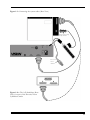
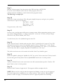
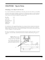
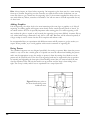
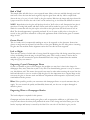
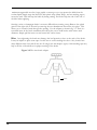
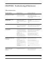
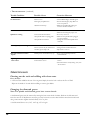
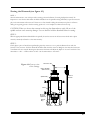
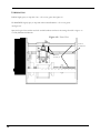
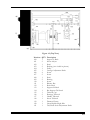
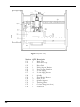
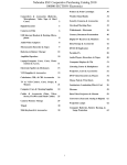
Instruction Manual
Table of Contents
Safety Instructions -------------------------------------------------- page 2
Chapter 1
Setting up the Vision Cylindrical System-------------------- page 3-6
Chapter 2
Quick Start to Engraving -------------------------------------- page 7-10
Chapter 3
Tips & Tricks ---------------------------------------------------- page 11-14
Chapter 4
Troubleshooting & Maintenance---------------------------- page 15-20
Appendix
A— Contacts --------------------------------------------------------- page 21
1
SAFETY PRECAUTIONS for The Vision Cylindrical Engraver
!"Keep hands clear of the spindle belt during operation.
!"Always stop the machine before making any adjustments.
!"Keep clear of adjustment knobs located on the rear, left and right side of the table.
!"Disconnect the table cable before servicing.
!"Do not operate the system with covers removed.
!"Wear safety glasses when cutting metal or when operating the system without a vacuum system.
!"Use extreme caution when inserting or removing cutters.
Disclaimer
The Vision Cylindrical Engraver Manual is Copyright ©1999 Vision Engraving & Routing Systems.
All rights reserved. No part of this publication may be reproduced, stored in a retrieval system, or transmitted in any form or by any
means, electronic, mechanical, photocopying, recording, or otherwise, without the prior written permission of Vision Engraving &
Routing Systems. No patent liability is assumed with respect to the use of the information contained herein. Neither is any liability
assumed for damages resulting from the use of the information contained herein.
Neither Vision Engraving & Routing Systems nor its affiliates shall be liable to the purchaser of this product or third parties for
damages, losses, costs, or expenses incurred by purchaser or third parties as a result of accident, misuse, or abuse of this product or
unauthorized modifications, repairs, or alterations to this product.
Vision Engraving & Routing Systems shall not be liable against any damages or problems arising from the use of any options or any
consumable products other than those approved by Vision.
Vision Cylindrical Engraving System, Vision Cylindrical Engraver, Vision Engraving Systems and Vision Engravers are registered
trademarks of Vision Engraving & Routing Systems.
2
CHAPTER 1 Unpacking and Setting Up Your
New Vision Cylindrical Engraver
•Step 1
Your Vision Cylindrical Engraver System has been packaged in 2 boxes. You may have received
additional boxes if additional accessory items were purchased. If you already own a Vision system
and are adding the cylindrical table only, you should have received only 1 box. Check each package
for external damage and report it immediately to your freight company and your local area Vision
sales representative.
NOTE: Save the shipping container for future service use.
•Step 2
Unpack all items and take inventory to ensure that all items are present before proceeding. You
should have received the following:
1- This Manual
1- Cylindrical Glass Engraver
1- Vision Control Unit and accessory pack (if purchased)
1- Vision Software CD
1- Recirculating Pump Power Supply
1- Tail Stock
1- Parallel Interface Cable
1- Spare Motor Belt
1- Cutting Oil
1- Diamond Graver Installed (11/64", .003 tip, 4.5" in length)
1- Cutter Wrench
1- Grease Pencil
1- Rub n’ Buff
1- Silicon Spray Lubricant
Optional items you may have received if you are connecting to an existing Phoenix engraver:
1- A/B Switch Box
1- Short Parallel Cable (Grey)
1- Software Update
•Step 3.
Place the engraving system on a level surface close to the control unit. Remove the Head Locking
Screws as shown in figure 1.1. Save these for later use. They are an integral part of the operation in
some engraving applications.
Be sure to remove all packing material from inside of the glass engraver. Remove any small debris to
ensure that the water recirculating system will be free from clogging.
3
Figure 1.1 • Stylus with
packing material
(Front View)
Head Locking Screws (4)
Tail Stock
•Step 4.
Connect the glass engraver to the system control unit as shown in figure 1.2. If you already own
a Phoenix engraver, connect the gray “table” cable to the A/B box as shown in figure 1.2a.
Ensure that all of the connections are solid by screwing down the cable screws.
NOTES: (1) You have the option of designating which system will be the “A” device. It is recommended that you assign the “A” to the system that you will operate the majority of the time. (2) If
your computer has only one parallel port and it is being used by your printer, you need to disconnect the printer cable, plug in the software key and plug the printer cable into the software key.
•Step 5.
Connect the recirculating pump power supply to the suge protector that was included with the
controller as shown in figure 1.2.
•Step 6.
Mix 1-gallon tap water with 1-2 tablespoons of cutting oil. It is recommended that only 1/2 gallon
be added to the holding tank, raising the level above the brass drain holes located on the outside
lower corners of the unit. At this time inspect for any leaks before proceeding. If no leaks are
found, add the remaining 1/2 gallon mixture. Ensure that the liquid level reaches above the
recirculating pump intake filter, approximately 1-1.5" deep. Add additional water as necessary.
•Step 7.
Power up the serial controller by flipping the “ON/OFF” switch in the rear. Allow 10-15 seconds
for the internal CPU to boot. Make sure that the emergency STOP button is NOT engaged, then
hit the “Drives On” key.
4
Figure 1.2 • Connecting the system cables (Rear View)
Recirculating
Pump Power
To 110v
wall
outlet
Figure 1.2a • The A/B Switchbox (Rear
View) for users of the Phoenix/Vision
Cylindrical Combo
5
•Step 8.
Now test the recirculating pump by hitting the AUX ON/OFF key on the control unit. Leave the
key in the red/green (AUX) position when finished. The keys on the serial controller are “tri-state”
switches with three positions: ON (displaying a green light), OFF (displaying a red light) or AUX
(displaying a red/green light).
NOTE: The pump may need to be primed. Repeating STEP 8 several times may be necessary to get
the liquid to fill the tubes.
•Step 9.
If you are connecting to an existing Phoenix system, simply load the Vision Software CD into your
computer and follow the installation procedures below. The software update will bring your version
of the Vision Software current and also provide the necessary driver to operate the cylindrical
engraving table.
If you are loading the software for the first time, follow the software installation procedures on page
9 in Chapter 5 of the Vision Serial Controller Operating Manual.
•Step 10.
Start your Vision Software program (any questions about starting the program will be answered by
the software operations manual).
•Step 11.
Click on the “System” menu and drag down to “save device change”. The “Save Settings” window
appears. Bypass this window by clicking on “okay”.
•Step 12.
In the “Save Settings 2” window, “serial engraver” should be selected, so click on “okay” again
•Step 13.
In the “Save Settings 3” window, click on “stylus” until it is highlighted and hit “okay”.
•Step 14.
A window appears that reads: “Settings have been saved”. Hit “okay”.
•Step 15.
Exit the Vision program and then restart the program (not the computer) to use the new settings.
NOTE: A warning may appear that reads: “Output device may be active”. Hit “okay” and proceed
to the next chapter for a quick start to Cylindrical Engraving.
6
CHAPTER 2 Quick Start to Cylindrical Engraving
In this chapter you will go through the easy steps to engrave a coffee mug. A piece has been supplied
for you to experiment on. Don’t be disappointed if the first cup you create does not come out
perfect. With just a couple of attempts you will master the simple process and techniques and be
well on your way to getting the most out of your cylindrical engraver.
Step 1.
You must turn off limits when you start to use the Vision Cylindrical Engraver. To do this, hit “F2”
then the “Goto Home” key on the controller. Using this sequence, the controller toggles between
using limit switches and not using limit switches. This sequence is used repeatecly when you have a
Phoenix/Vision Cylindrical Combo system because the Phoenix has limit switches, but the Vision
Cylindrical does not.
NOTE: If you are using the Phoenix and want to change to the Vision Cylindrical Engraver, hit
“F2” then “Goto Home” before you change the A/B switch to the Vision Cylindrical Engraver. If you are using the Vision Cylindrical Engraver and want to switch to the Phoenix, hit
“F2” then “Goto Home” before you change the A/B switch to the Phoenix.
Step 2.
Refer to figure 2.1. By turning the black carriage adjustment knob located on the left side in the rear
of the unit, you can move the carriage out of the way to insert the coffee mug. You can
also move the carriage out of the way by using the controller jog keys, however, once
jogged from the controller, the knobs are then locked and you must continue to use
the jog keys from that point on.
Step 3.
The UP/DOWN Jog Keys will move the
carriage
Insert the mug as shown in figure 2.1 (top of the mug to the right), and move the tail stock over
until the mug is held in place. This is done by lifting the metal bar out of the grooved slots and
replacing in the grooves farther to the left. Rotate the tail stock handle to tighten or loosen to get a
secure hold on the mug. Care must be taken to center the cup in the tailstock and headstock.
NOTE: Do not over tighten. The friction of the rubber surfaced head and tailstock is generally
sufficient to hold most items in place. Lightly tighten. Over time you will become experienced with
the feeling of a secure mug or glass.
To ensure that the mug handle is not going to interfere with the engraving head,
simply rotate the secured mug until the handle is facing you as shown in figure
2.1.
The LEFT/RIGHT Jog Keys will rotate the head/
tailstock
7
Figure 2.1 • Top view of Vision Cylindrical Engraver with mug (note that mug handle is positioned
to the front of the unit
carriage
adjustment
knob
carriage
spindle
tail/head
stock
adjustment
knob
tail stock
head stock
metal bar for moving
the tail stock
Figure 2.2 • Lowering the carriage with the head
release tab. Shown is a close-up view from the right
front side of the carriage.
grooved slots
head release tab
place fingers under carriage here
8
wine bottle
adapter
cover
NOTE: Before moving on to the next step, make sure that the carriage is positioned to the left of
the tailstock.
Step 4.
With one hand supporting the carriage, gently lower the carriage by releasing the head release lever
as shown in fugure 2.2. Lower the head to the mug surface and rest the feet of the carriage on the
mug.
We have previously set up the Cylindrical Engraver with a cutter and adjusted it for this quick start.
Other cutters may be used and adjustments for this may be found in Chapter 3. You will not need to
change anything for our coffee mug.
Step 5.
Hit the UP/DOWN Jog keys to move the engraving head directly over the center of the mug. Don’t
worry if it is not perfectly centered. You will discover that the accuracy is relative and can be more
precisely adjusted after some experience.
Step 6.
Hit the “Z Jog” UP arrow as far as it will go.
Then hit “Set Offset”.
NOTE: Make sure that the “Drives On” key is lit green. You will now be able to set the surface and
cutter lift to clear the engraving surface between characters. Properly setting the surface will also
ensure that the cutter does not cut too deeply.
Step 7.
To set the surface lift, hit the “Z Jog” DOWN key
until the nose
cone rests on the mug surface. Then hit the “Z Jog” DOWN key again
to “overtravel” the nose a bit more to ensure that the curvature and
other imperfections of the surface are taken into account. To know if
“overtravel” was sufficient, see figure 2.3.
Look for the slight gap between the two
plates
under the visible section of the Z Lead
Screw
Step 8.
Fig.2.3 • Right side view
of the carriage. Note that
the gap between plates is
exaggerated--important is to
see that lower plate is NOT
pushing on upper plate.
Hit the “Set Surface/Lift” key. The carriage will raise up to its clearance level.
If you require more clearance, hit the “Z Jog” UP key to reach the desired
level. Hit the “Set Surface/Lift” key again and the spindle will rise to the
home position. You are now ready to create a layout for engraving.
9
Step 9.
Start the Vision program. Using the mouse select FILE and open a NEW JOB.
If you have never created a layout with the Vision program, refer to the
software manual to familiarize yourself with the basic program features.
The following is a sample job:
Step 10.
Select F5 to create an autolayout. This will greatly simplify the process and give you a perfectly
centered layout. Type in the following:
Plate width = 2.000".
Plate height = 1.000".
Number of Lines = 2.
Using the mouse, click “okay”.
Step 11.
On line 1 type your first name and hit enter or carriage return. Add an appropriate greeting or message such as “Happy Birthday” or “Happy Anniversary” on line two. To view your layout simply
select the F8 key. When finished, click “okay”.
To send the new job to the cylindrical engraver select F9.
Step 12.
In the “Execute Layout” window, make sure that “Stylus” is checked in the “output to” box. This
will ensure that the job is sent to the cylindrical engraver. Click on “Rotary Axis”. In the “Rotary
Setup”, enter the diameter of the mug. Most mugs are approximately 3.0". Even if you calculation is
off, the only affect will be a slightly expanded or condensed text. Hit “okay”.
The job has now been sent to the control unit and the “Start” key should be green.
Step 13.
Pretest the spindle by hitting the “Spindle On/Off ” key on the Vision control unit. The key should
be in the red/green AUX position. Set the “Spindle RPM” knob to the 3 o’clock position.
Step 14.
Turn the “Z Dwell” knob on the control unit to the full counterclockwise position. Turn the “XY
Speed” knob to the 10 o’clock position.
Step 15.
Press the “Start” button to begin the job. The engraver will then complete the job.
NOTE: When you look at the job after the engraver has finished, you may not see the engraved
lines on the mug as they are difficult to see on many surfaces. This is why the “Rub and Buff ”
product is useful. See page 3.3 for directions on how to apply this product for color filling.
10
CHAPTER 3 Tips & Tricks
Attempting a new shape for the first time
If you cannot determine the actual diameter of the object, select the closest object you are familiar
with and use that number. Its helpful to develop a list of diameters for glasses you offer and keep it
posted next to the engraver for quick reference. If you are using Libby Glass, the below table lists
some common sizes and may be helpful if just getting started.
Beer Mug
Coffee Cup
Rocks Glass
Fluted Champagne
Large Wine
Medium Wine
Small Wine
2.8"
3.4"
3.0"
2.2"
3.4"
3.0"
2.7"
If a small portion of the engraved image drops out or an area of the cut is missed, recut the entire
image by repeating the job. Do not move the engraving head laterally; this will create a shadow or
duplicate image. It’s always better to lift the head and inspect the work before removing the object.
Accurate realignment is virtually impossible.
Be aware of the limitations of the engraving head when sizing the engraving job. Figure 3.1 shows
an example of how the head could run into the head or tail stock as well as the lip of a glass or
object.
Figure 3.1•Close-up view
of the front of the carriage
resting on the mug. Engravable
area is limited to the edge of the
mug or glass LESS the distance
between the spindle and the feet.
carriage
feet
11
Hint: Always inspect an object before engraving. On inexpensive glass there may be a seam running
from top to bottom. Engraving over the seam may not yield the best results. Sometimes you can
rotate the object to get a better area for engraving. Also, if the customer supplied the item to be cut,
note with them any defects, scratches or blemishes. You will not want to be held responsible for any
of these later.
Adding Graphics
Like all engraving, the object looks a lot more interesting with some logo or graphics on it. Like all
engraving, an outline graphic will engrave more cleanly and in a much shorter period of time if it’s
an outline with no fill. This is especially important when cutting glass. Too much engraving or fill
may weaken the glass or crystal as well as make the engraving set up more difficult. Accurate fills are
very critical when using a diamond of only .003 to .005 wide. Run time will be affected especially if
a large overlap is used to insure that the fill is complete and without voids.
Its recommended that you experiment with different cutters and fill patterns to get the results you
expect. When possible, try to avoid graphics with excessive amounts of engraving fill.
Doing Pewter
The cylindrical engraver was not designed specifically for cutting on pewter. Many times the pewter
surface is very soft or has a visible grain to it. Special care must be taken when handling the pewter
and it may be appropriate to tape the surface to protect it from the carriage feet. Shadows on the
pewter may be caused by rub of the feet. The engraving head may be supported in the up position
by inserting and tightening the front pair of head-locking screws that you removed when the unit
was first unpacked. This will lock the head in an up position and also keep it from tilting left to
right. The set-up is tricky and it’s best to experiment on a scrap object first.
Figure 3.2•Arrows point to
the front head-locking screw
lockdown areas.
12
Rub n’ Buff
This simple filler will add class to your engraved items. Many colors are available through your local
craft store. Once the item has been engraved, wipe the glass clean and dry. Add a couple beads
(about the size of a pea), of rub n’ buff to the glass surface. Rub into the image and wipe clean with
a paper towel. Do not leave the rub n’ buff on the surface long or it will become difficult to remove.
NOTE: Imperfections in the glass will pick up the rub n’ buff color as well. Inexpensive bar glass is
notorious to having little marks and dents. Extra work will be needed to get it out of these areas.
Watch for seams that will also pick up the color. Most clear glass items will look better if left unfilled. The frosted appearance is generally preferred. If you do want to add color to clear glass or
crystal, try the gold colors offered for a classy rich appearance. Rub n’ Buff works great on ceramic
mugs as well.
Grease Pencil
This is a handy tool for temporarily marking an area to be engraved on the glassware. Some wineglasses or mugs must be engraved on both sides of the glass. Marking the two sides prior to inserting
the glass into the machine makes alignment easier after one side has been engraved.
Left vs. Right
There are two choices of which side of a mug should be engraved: the side facing toward the person
as they are drinking from the mug or the side facing away. This is really a mater of choice but remember to give the customer the option. Remember that once a mug is inserted into the machine
using the jog keys can rotate it.
Engraving Crystal Champagne Flutes
Crystal is as durable as glass in most designs; the problem you may face is that in the shape of a
champagne flute, many times the crystal is very thin. The manufacturing process is set up to create a
very thin delicate wall. This means that special care must be taken when securing the crystal into the
head and tailstock so as not to crush or chip the glass. It’s also important not to engrave deep as this
can cause the glass to become weak and fracture. Experiment with inexpensive crystal until you feel
comfortable with the process.
Hint: When possible, provide your customers with champagne flutes or crystal stemware that you
supply. You can control the quality and durability better and, cut the cost to replace damaged or
defective pieces.
Engraving Wine or Champagne Bottles
The bottle adapter is required for this process.
Champagne and wine bottles make great gifts as well as appropriate additions to gift baskets. Not
everyone cares about the winery that produced the wine or the vintage and often times, part of the
bottles’ mystique and beauty is caused by the label. You can soak off the label to give you the
13
maximum engraveable area for a large graphic or message or you can protect the label from the
coolant liquid. Simply wrap the label area with plastic wrap (Saran Wrap), and use masking tape to
secure the ends. This will keep the label dry during cutting. It will also keep the rub n’ buff off of
the label when applying.
Securing a wine or champagne bottle is no more difficult than securing a mug. Remove the splash
guard on the right side of the unit by removing the two thumbscrews that secure it in place. This
allows you to extend a bottle through the opening. Use the adapter as shown in fig 3.3. There is a
reversible insert in the bottle attachment that allows the user to hold bottles with various neck
diameters. Simply pull the insert out and rotate 180° and re-insert.
Hint: Over tightening the bottle may damage the lead protective sleeve at the neck of the bottle.
It may be helpful to place some tape over the area to avoid crushing the sleeve. Also, bottles have
many different neck sizes and all may not fit snugly into the adapter. Again, a little masking tape may
help to fill the void and allow for proper securing of the bottle.
Figure 3.3•The wine bottle adapter
Insert
14
CHAPTER 4 Troubleshooting & Maintenance
•TROUBLESHOOTING
Trouble Condition
Possible Cause
Corrective Measure
System will not move to limits
•Is the power cord connected?
•Is the power strip/source on?
•Connect the power cord securely.
•Turn on the main power strip.
•Use the software feature Run: Move to Limits
to test your limits.
Pump does not turn on / has
very limited flow
•Check to see that enough liquid is in
the basin of the engraver.
•Check to see if debris is clogging the
pump.
•Use 1 Gallon of water to 1 Teaspoon of oil —
fill to the line..
•Make sure the vents to the pump motor are
clear.
Engraves on one axis only
•Is the power cord connected?
•Are any external objects blocking the
travel of the moving parts in the
machine.
•Connect the power cord securely.
•Move the handle of the mug or anything else
interfering with the engraver’s mechanics.
Uneven or ragged characters on
the finished piece
•Are all cables connected?
•Are any external objects blocking
the movement of the mechanics?
•Is the diamond graver tip damaged
or worn?
•Engraving too fast.
•Depth settings are incorrect.
•Mug or glass object may not be
secure in the tail and head stock.
•Secure all cable connections.
•Move the handle of the mug or anything else
interfering with the engraver’s mechanics.
•Replace the diamond graver tip.
•Is the diamond graver tip damaged
or worn?
•Replace the diamond graver tip.
•Recirculating pump is not on.
•Turn the recirculating pump on.
•Mug or glass object may not be
secure in the tail and head stock.
•Engraving too deep or too much
tool pressure.
•Some glass has imperfections that
may weaken it.
•Adjust the item in the tail and head stock.
The glass chips or breaks on the
finished piece
Main switch light or front panel
LED indicators will not
illuminate
•Is the power cord connected?
•Is the power strip/source on?
•Try slowing down the X-Y movement.
•Reduce depth to eliminate chip out.
•Adjust the item in the tail and head stock.
•Reduce engraving depth or tool pressure.
•Attempt the same job with another piece of
glass.
•Connect the power cord.
•Turn on the main power strip.
•Check the main power fuses.
15
• TROUBLESHOOTING (continued)
Trouble Condition
Possible Cause
Corrective Measure
No XYZ motion
•Drives not on
•Emergency Stop Button in
•Check LED Ind light, should be green.
•Ensure the Emergency Stop Button is
in the out position.
•Make sure the table cable is plugged
into the controller and table.
•Table not hooked up
Drives will not turn on
•Table cable not connected
Spindle not working
•Is the Controller turned off?
•The spindle cable is not plugged in
•The spindle fuse is blown
•Connect table cable.
•Make sure the emergency stop is out.
•If it is off, turn it on.
•Make sure the spindle cable is plugged
in to the controller.
•Change the fuse marked spindle in the
controller.
Auxiliary (AUX) not working
•Is the Controller turned off?
•If it is on, there may be a blown fuse.
•Auxiliary power strip is off.
•If it is off, turn it on.
•Change the fuse marked AUX fuse.
•Flip switch to turn on.
Slow drop at the bottom of the
Z path.
•Dwell speed is turned all the way up.
•If it is, turn the dwell speed knob
counterclockwise.
Engraving head does not lower
to the surface.
•Surface setting is not set.
•Limit switches are on.
•Set the surface via the “Set surface/Lift”
button.
•Turn limit switches off by hitting “F2”, then
“Goto Home”.
•MAINTENANCE
Cleaning out the tank and refilling with clean water
Every 30 days:
• A valve has been added at the rear of the engraver. Simply loosen the bolt to release the flow of fluid.
Wipe out the inside of the tank before refilling to remove glass debris.
Changing the diamond graver
Note: The spindle and diamond graver have reverse threads.
• The diamond graver may be removed by turning the brass cutter knob clockwise. Slide out the old cutter and
insert the new one. If adjustment is necessary, you may loosen the set screw that holds the cutter shank in the knob
using a cutter wrench. Tighten the knob firmly. Never use pliers.
* The Diamond Graver is 11/64", .010" tip, 4.5" in length.
16
Zeroing the Diamond (see figure 4.1)
STEP 1.
Turn the micrometer to zero. This provides a starting point and reference for setting the depth accurately. It’s
important to note that the micrometer should be threaded onto the spindle housing sufficiently to prevent excessive
play in the micrometer and nosecone. If there are too few threads holding the micrometer in place it will move
during the engraving process. The best starting position is 3 or 4 complete revolutions from the top.
CAUTION: When you loosen the setscrew in this step, the diamond may easily fall out of the
spindle and can cause cutter tip damage. Use one hand to hold the diamond before loosening.
STEP 2.
With the appropriate diamond installed in the spindle, loosen the setscrew in the brass cutter knob with a spline
wrench (commonly referred to as the cutter wrench).
STEP 3.
Gently place a piece of metal (brass preferred) against the nosecone so as to push the diamond even with the
bottom of the nosecone. Now the diamond should be flush with the nosecone. Retighten the cutter knob setscrew.
Your diamond is now zeroed. Rotating the micrometer clockwise will adjust the depth of the cut. Each click of the
micrometer = .001”. A full revolution is .025”. Set the micrometer to .001-.003”.
Figure 4.1•Close-up view
of the carriage
Diamond Cutter
Brass Cutter Knob
(with set screw)
Spindle Pulley
Reverse
Threads
Pointer
Micrometer
(for depth
adjustment)
Retainer
Ring
Nosecone
Diamond Tip
17
LUBRICATION
RAILS• Lightly spray or wipe with 3 in 1—do not use grease. See figure 4.2.
LEADSCREW• Lightly spray or wipe with silicone-based lubricant—do not use grease.
See figure 4.2.
Spray the length of the stainless steel rails and the leadscrew and move the carriage from left to right so as
to evenly distribute the lubricant.
Figure 4.2 • Front View
Lubricate
the leadscrew
Lubricate
the rails (4)
18
Figure 4.3 (Top View)
Number
100
101
102
103
104
105
106
107
108
109
110
111
112
113
114
115
116
117
118
119
120
121
QTY
1
2
1
2
1
1
4
2
1
2
1
1
1
1
1
1
2
1
1
1
1
1
Description
Support L–Rack
Screw–Adjust
Shaft
Bushing (not visable in picture)
Pulley
Carriage Adjustment Knob
Screw
Screw
Shaft
Bearing
Screw
Balance Bar
Rack–Back
Support–R–Rack
Bar Support Tail Stock
Tailstock Cap
Bearings Tailstock
Handle Tailstock
Screw Tailstock
Diamond Cutter
Guard–Splash–Right Side
Tail/Head Stock Adjustment Knob
19
Figure 4.4 (Front View)
Number
121
122
123
124
125
126
127
128
129
130
131
132
133
134
20
QTY
1
1
1
1
2
2
4
1
1
2
2
2
1
1
Description
Rack Front
Head Stock Cap
Drive Belt
Pulley Support Bracket
Head Locking Brackets
Z-Axis Springs
Z-Axis Spring Screws
Spindle
Head Release Button
Shaft Z-Axis
Spindle Supports
Tracking Rollers
Coolant Pump (not shown)
Leadscrew
APPENDIX A Contacts
AMACO
LIBBEY INC.
(AMERICAN ART CLAY COMPANY, INC.)
Glassware manufacturer
Corporate Headquarters
420 Madison Avenue
P.O. Box 10060
Toledo, OH 43699-0060
(419) 727-2100
The maker of Rub ‘n Buff
4717 West 16th Street
Indianapolis, IN 46222
(800) 374-1600
ANCHOR
HOCKING
Specialty glass suppliers
2893 W. Fair Ave.
Lancaster, OH 43130
(800) 848-7200
CARDINAL INTERNATIONAL
Glassware manufacturer
30 Corporate Drive
Wayne, NJ 07470
(201) 628-0900
DURAND INTERNATIONAL
MARCK & ASSOCIATES
Ceramic cup suppliers
300 Phillips Ave.
Toledo, OH 43612
(419) 478-0900
GLOBAL INDUSTRIES, INC.
Suppliers of ceramic glassware, mugs & cups
3800 West 80th St. Suite 1280
Minneapolis, MN 55431
(800) 678-5609
Glassware suppliers
660 S. Figueroa Street #1650
Los Angeles, CA 90017
(213) 624-2609
21