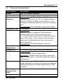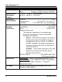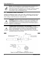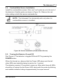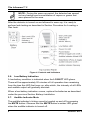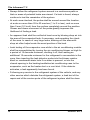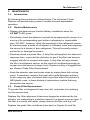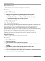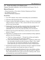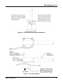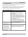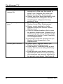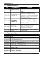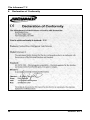
1
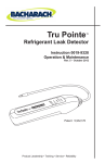
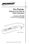
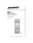
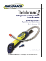
Refrigerant / Combustibles Leak Detector Instruction 0019-9211 Operation and Maintenance Rev. 9 – November 2012 Pat. 6,362,741, D447,071 Product Leadership • Training • Service • Reliability The Informant™ 2 ii 0019-9211 Rev 9 The Informant™ 2 COMBUSTIBLE REFRIGERANT GAS WARNING: For your safety, DO NOT use the Informant 2 with the refrigerant sensor to detect refrigerants which are rated as combustible/flammable gases (e.g. ASHRAE - A2 or A3 rated refrigerants). Use with combustible/flammable refrigerant gases can cause an explosion resulting in death or severe injury. Register Your Warranty by Visiting www.mybacharach.com WARRANTY Bacharach, Inc. warrants to Buyer that at the time of delivery this Product will be free from defects in material and manufacture and will conform substantially to Bacharach Inc.’s applicable specifications. Bacharach’s liability and Buyer’s remedy under this warranty are limited to the repair or replacement, at Bacharach’s option, of this Product or parts thereof returned to Seller at the factory of manufacture and shown to Bacharach Inc.’s reasonable satisfaction to have been defective; provided that written notice of the defect shall have been given by Buyer to Bacharach Inc. within one (1) year after the date of delivery of this Product by Bacharach, Inc. Bacharach, Inc. warrants to Buyer that it will convey good title to this Product. Bacharach’s liability and Buyer’s remedy under this warranty of title are limited to the removal of any title defects or, at the election of Bacharach, to the replacement of this Product or parts thereof that are defective in title. THE FOREGOING WARRANTIES ARE EXCLUSIVE AND ARE GIVEN AND ACCEPTED IN LIEU OF (I) ANY AND ALL OTHER WARRANTIES, EXPRESS OR IMPLIED, INCLUDING WITHOUT LIMITATION THE IMPLIED WARRANTIES OF MERCHANTABILITY AND FITNESS FOR A PARTICULAR PURPOSE: AND (II) ANY OBLIGATION, LIABILITY, RIGHT, CLAIM OR REMEDY IN CONTRACT OR TORT, WHETHER OR NOT ARISING FROM BACHARACH’S NEGLIGENCE, ACTUAL OR IMPLIED. The remedies of the Buyer shall be limited to those provided herein to the exclusion of any and all other remedies including, without limitation incidental or consequential damages. No agreement varying or extending the foregoing warranties, remedies or this limitation will be binding upon Bacharach, Inc. unless in writing, signed by a duly authorized officer of Bacharach. NOTICE Product improvements and enhancements are continuous, therefore the specifications and information contained in this document may change without notice. Bacharach, Inc. shall not be liable for errors contained herein or for incidental or consequential damages in connection with the furnishing, performance, or use of this material. No part of this document may be photocopied, reproduced, or translated to another language without the prior written consent of Bacharach, Inc. Copyright © 2000-2012, Bacharach, Inc., all rights reserved. BACHARACH® is a registered trademark of Bacharach, Inc. Informant™ is a trademark of Bacharach, Inc. All other trademarks, trade names, service marks and logos referenced herein belong to their respective companies. 0019-9211 Rev 9 iii The Informant™ 2 TABLE OF CONTENTS 1. OVERVIEW ................................................................................................................ 1 1.1. Introduction..................................................................................................... 1 1.2. Features ......................................................................................................... 2 1.3. Technical Characteristics ................................................................................ 3 2. OPERATION .............................................................................................................. 5 2.1. Battery Installation .......................................................................................... 5 2.2. Sensor Installation Overview........................................................................... 5 2.3. Refrigerant Sensor Installation ........................................................................ 6 2.4. Combustibles Sensor Installation .................................................................... 7 2.5. Turning the Detector On and Off ..................................................................... 7 2.6. Low Battery Indication .................................................................................... 8 2.7. Audible Indicator Mute .................................................................................... 8 2.8. Locating a Gas Leak ....................................................................................... 9 2.9. Sensor Failure Indication ...............................................................................10 2.10. False Refrigerant Indication ...........................................................................10 2.11. Refrigerant Sensor Flooding Indication ..........................................................11 2.12. SAE Refrigerant Leak Detection Tips .............................................................11 3. MAINTENANCE ....................................................................................................... 13 3.1. Introduction....................................................................................................13 3.2. Routine Maintenance .....................................................................................13 3.3. Probe Filter Replacement ..............................................................................13 3.4. Sensor Replacement .....................................................................................14 3.5. Probe Assembly or Fan Replacement ............................................................15 4. TROUBLESHOOTING ............................................................................................. 19 5. PARTS AND SERVICE ............................................................................................ 21 5.1. Complete Kits ................................................................................................21 5.2. Optional Accessories .....................................................................................22 5.3. Replacement Parts ........................................................................................22 5.4. Sales/Service Centers ...................................................................................23 6. Declaration of Conformity ...................................................................................... 24 iv 0019-9211 Rev 9 The Informant™ 2 1. OVERVIEW 1.1. Introduction The Informant 2 Dual Refrigerant / Combustibles Leak Detector (Figure 1) is a portable, battery powered instrument designed to pinpoint the location of either refrigerant or combustible-gas leaks using separate, interchangeable sensors. The type of gas detected depends on the sensor installed. The detector is designed to be quickly responsive, even when high levels of background vapors or gases are present. No manual sensitivity adjustments are necessary during the inspection process. The Informant 2 is suitable for HVAC Service Technicians, Gas Utility Personnel, Automotive Service Facilities, and Plant Maintenance Departments who are in need of a small, lightweight and rugged instrument that is capable of pinpointing small to large refrigerant leaks as those found in air-conditioning units, and automobile engine compartments, as well as locating combustible gas leaks in residential appliances and furnaces, industrial heating units, and gas distribution equipment.’ Figure 1. The Informant 2 Leak Detector 0019-9211 Rev 9 1 The Informant™ 2 1.2. Features • Detects the presence of either refrigerants or combustible gases (with appropriate sensor installed) • Sensors that represent the latest advancements in sensor technology • Microprocessor-controlled circuitry that guarantees accuracy and reliability • Dual bar-graph LEDs provide visual indication of the refrigerant/combustibles level from a wide variety of viewing angles • Audible refrigerant/combustibles level indicator with mute feature • Flashing probe tip whose flash rate varies in accordance with changes in the detected refrigerant/combustibles level • Automatic zero and background compensation that allows a leak to be quickly found in contaminated atmospheres without requiring manual sensitivity adjustments • Flexible probe that allow it to be either “docked” in its storage position for close-up leak testing, or unfolded to its maximum length of 20 inches (508 mm) for locating leaks in hard-to-reach areas • Long-life fan provides positive airflow past sensor resulting in a faster response time • Filter in probe tip prevents water from reaching sensor • One-handed operation • No calibration required • Batteries included • Optional protective rubber boot, includes a cavity that ® accommodates a Maglite flashlight • One year warranty • Extended warranty available • Made in U.S.A. 2 0019-9211 Rev 9 The Informant™ 2 1.3. Technical Characteristics Specification Power Warm-Up Time Gases Detected Response Time Sensitivity Sensitivity Adjustment Battery Life Sensors Probe Sampling System Flow Rate Weight 0019-9211 Rev 9 Description Four ‘AA’ Alkaline Batteries 10 seconds Refrigerants: All CFC, HCFC and HFC refrigerants including: R-12, R-22, R-123, R-134a and blends R-404A, R-408A, R-409A, and R-410A (i.e., any refrigerant containing Chlorine, Fluorine or Bromine gas). Combustibles: All combustible gases and vapors. 0.2 seconds Refrigerants: 0.5 oz/year (14 g/yr) of R-134a (hardest to detect refrigerant) as detected by moving probe tip at 2" (50 mm) per second, 0.1" (3 mm) above leak source. A leak rate of less than 0.25 oz/year (7 g/yr) can be detected when probe tip is held steady over leak source for at least 5 seconds. Combustibles: 50 ppm Methane, minimum. Automatic 4–5 hours, under typical intermittent operation Combustibles: Semiconductor type with a typical 5 year life span, plug-in replacement. Refrigerant: Heated Diode type with a typical life span of 150 hours or 1 year of normal use, plug-in replacement. Flexible gooseneck, 20 inch (508 mm) maximum length [reduces to 3 inches (76 mm) when wrapped around instrument], includes integral sensor, filter, and LED 40 to 50 cc/min with sensor installed 0.86 lb (0.39 kg) w/ batteries 3 The Informant™ 2 Specification Switches Size W×L×H (Excludes Probe) Operating Environment Visual and Audible Indicators Approvals CE Mark 4 Description Power ............................ Toggles detector ON/OFF Mute.................. Toggles audible indicator ON/OFF 1.75 x 9.62 x 2.25 inches 44.50 x 244.30 x 57.20 mm Position ............................................................. Any Temperature .................... 32 to 122 °F (0 to 50 °C) Humidity ............... 15 to 90% RH, non-condensing Power On ..............................................Green LED Low Battery .............................................. Red LED Mute...................................................... Amber LED Relative Gas Level: The detector responds to increasing gas levels by activating its visual and audible indicators as follows: Visual – Dual LED bar-graphs (located on the top and rear of the detector) begin to progressively glow in series. In addition, an LED located in the probe tip begins to increase its blink rate from an idle rate of once-per-second. Audible – The audible indicator’s tick rate begins to increase from its idle rate of one-tick-per-second. Sensor Failure ....................... The middle gas-level LED glows steadily Refrigerant: Listed in accordance to SAE J1627 Combustibles: Lab certified to UL913, intrinsically safe for use in Class I, Division 1, Group D hazardous areas Independently tested in accordance with EMC Directive 2004/108/EC 0019-9211 Rev 9 The Informant™ 2 2. OPERATION 2.1. Battery Installation WARNING: Explosion hazard. To reduce the risk of igniting a flammable atmosphere, batteries must only be changed in an area known to be non-flammable. NOTE: To maintain agency approval, use only the following types of ‘AA’ batteries: Energizer E91; Duracell MN1500; Rayovac 815; and Panasonic AM-3PI. 1. See Figure 2. Using a #1 Phillips screwdriver, first loosen the battery door screw located at the rear of the detector; then remove the door. 2. Install four ‘AA’ alkaline batteries into the detector, observing the polarity markings that are molded on the side of the case. 3. Reinstall the battery door and tighten its screw. Figure 2. Battery Installation 2.2. Sensor Installation Overview Before leak testing can begin, the appropriate sensor must be installed. If you have a combustibles-only or refrigerant-only detector, then simply install the sensor that was supplied with the detector. If, however, you have a dual detector, then install the sensor that corresponds to the gas that will be detected during the inspection process. For the detector to maintain agency approval, the blue probe tip must be used with refrigerant sensor 0019-0510, while the red probe tip must be used with combustibles sensor 0019-0499. The color-coded probe tips allow an operator to easily identify which sensor is installed — “blue” for refrigerants, and “red” for combustibles. 0019-9211 Rev 9 5 The Informant™ 2 NOTE: For dual detectors, the red probe tip will not screw onto a probe that has a refrigerant sensor installed. This feature safeguards against the possibility of an operator mistakenly thinking that a detector with a refrigerant sensor is configured to detect combustibles. See the WARNING below. 2.3. Refrigerant Sensor Installation Install the refrigerant sensor, filter, and “blue” probe tip onto the end of the detector’s flexible probe as shown in Figure 3a. Observe the blue color coding on both the sensor and probe tip. WARNING: Explosion hazard. DO NOT use the Informant 2 with its refrigerant sensor installed in an area that is classified by the National Electrical Code as being a hazardous location where a potential for explosion or fire exist because of flammable gases or vapors in the atmosphere. COMBUSTIBLE REFRIGERANT GAS WARNING: For your safety, DO NOT use the Informant 2 with the refrigerant sensor to detect refrigerants which are rated as combustible/flammable gases (e.g. ASHRAE - A2 or A3 rated refrigerants). Use with combustible/flammable refrigerant gases can cause an explosion resulting in death or severe injury. Figure 3a. Sensor Installation (Refrigerant Sensor) 6 0019-9211 Rev 9 The Informant™ 2 2.4. Combustibles Sensor Installation Install the combustibles sensor, filter, and “red” probe tip onto the end of the detector’s flexible probe as shown in Figure 3b. Observe the red color coding on both the sensor and probe tip. NOTE: The Informant 2 is intrinsically safe only when its combustibles sensor is installed. Figure 3b. Sensor Installation (Combustibles Sensor) 2.5. Turning the Detector On and Off See Figure 4. The detector is toggled ON and OFF by pressing the POWER button. When first turned on, observe that the Power LED glows and that all other LEDs are tested by being turned on for 1 second. The detector requires 10 seconds to warm up. After which time all LEDs should be off except for the Power LED, along with the probe tip blinking and audible indicator ticking at approximately once-per-second. 0019-9211 Rev 9 7 The Informant™ 2 NOTE: During the warm-up period, the detector has zeroed out any background concentration of vapors or gases that were present in the area. After the detector is turned on and allowed to warm up, it is ready to perform leak testing as described in Section Procedure for Locating a Gas Leak. Figure 4. Controls and Indicators 2.6. Low Battery Indication A low-battery condition is indicated when the LO BATT LED glows. There will be approximately 20 minutes of full operation time remaining from the time this LED first turns on; after which, the intensity of all LEDs and audible output will gradually diminish. When a low-battery indication occurs, replace the batteries as described under the previous Section Battery Installation. 2.7. Audible Indicator Mute The audible indicator’s ticking sound is toggled on and off by pressing the MUTE button. Observe that the MUTE button’s amber LED glows when the audible indicator is turned off. 8 0019-9211 Rev 9 The Informant™ 2 2.8. Locating a Gas Leak After the detector is turned on and allowed to warm up, observe that none of the gas-level LEDs should be glowing. Also note that both the probe tip should be blinking and the audible indicator ticking once per second. All of these indicators show that the detector is currently not detecting a change in gas concentration. IMPORTANT: The detector’s function is to detect a change in gas levels, and not to make a quantitative measurement of the level. The technique of locating a leak by detecting a change in level allows an operator to quickly locate the source of a leak without making manual sensitivity adjustments, or being concerned about the background vapor or gas level in the surrounding area. Leak testing can be performed with the probe either “docked” in its storage position for close-up leak testing, or unfolded to its maximum length of 20 inches (508 mm) for locating leaks in hard-to-reach areas. Begin leak testing by slowly moving the probe toward the area to be tested. If surfaces are dirty or wet, wipe them off with a clean shop towel to prevent the filter from clogging. Avoid allowing water to enter the probe tip. When the detector first “sees” an increased gas level, all gas-level LEDs immediately glow along with the probe tip blinking and audible indicator ticking at a very rapid rate. If movement of the probe is stopped for more than 10 seconds, the detector’s automatic self-zero feature will cause all gas-level LEDs to turn off, along with decreasing the blinking and ticking rate of the probe tip and audible indicator, respectively. Once the presence of gas has been determined and the detector allowed to self zero, moving the probe toward the source of the leak will once again cause the detector to respond in a positive manner. After which, if the probe is moved away from the leak source, the detector will respond with a lower gas-level indication. 0019-9211 Rev 9 9 The Informant™ 2 CAUTION: When using the refrigerant sensor, note that exposing this sensor to a steady stream of highly concentrated refrigerant will severely reduce sensor life or damage the sensor. Sensor life is directly proportional to the amount of refrigerant that passes through the sensor. As for the combustible sensor, exposing it to a high concentration of combustible gas may temporarily make the detector less responsive to lower gas levels. If this occurs, move the detector to an area of fresh air for several minutes to purge the sensor of gas. Use the following general procedure to pinpoint the source of a leak: 1. Move the probe tip along the lines that are carrying gas and around the fittings until the detector responds in a positive manner. 2. Continue moving in the same direction as long as the detector’s gaslevel LEDs remain at full scale. This indicates that the gas concentration is increasing. 3. Once the source of the leak has been passed, the detector’s gas level indicators will all begin to decrease. At this point, reverse the direction of probing. As the probe tip is moved back and forth across the leak, the detector will automatically adjust its sensitivity to allow the user to pinpoint its source. 2.9. Sensor Failure Indication A sensor failure is indicated by the middle gas-level LED on both displays glowing steady. Refer to the Troubleshooting Guide Section of this manual for information on how to clear this condition. 2.10. False Refrigerant Indication False refrigerant indications are usually caused by abnormal changes in sensor temperature. These temperature changes are typically due to a sudden change in air flow past the sensor, or the sensor being heated by an outside source. To avoid false refrigerant indications, DO NOT . . . • allow the probe tip to become clogged with dirt, • allow the probe’s filter to become covered with water, 10 0019-9211 Rev 9 The Informant™ 2 • • • use the detector in windy areas, move the probe tip back and forth faster than 2" per second, allow the probe tip to contact a hot surface. 2.11. Refrigerant Sensor Flooding Indication When the refrigerant sensor becomes flooded with a high concentration of gas, observe that the gas-level LEDs quickly light full scale and then all turn off, leaving both the audible tick rate and probe tip blink rate at elevated levels. When this condition occurs, move the detector to an area of fresh air until all indicators return to their idle state. 2.12. SAE Refrigerant Leak Detection Tips The following was derived from SAE Surface Vehicle Standard J1628, Technician Procedure for Using Electronic Refrigerant Leak Detectors for Service of Mobile Air-Conditioning Systems: • The electronic leak detector shall be operated in accordance with the equipment manufacturer’s operating instructions. • Leak test with the engine not in operation. • The air conditioning system shall be charged with sufficient refrigerant to have a gauge pressure of at least 340 kPa (49 psi) when not in operation. At temperatures below 15 °C (59 °F), leaks may not be measurable, since this pressure may not be reached. • Take care not to contaminate the detector probe tip if the part being tested is contaminated. If the part is particularly dirty, it should be wiped off with a dry shop towel or blown off with shop air. No cleaners or solvents shall be used, since many electronic detectors are sensitive to their ingredients. • Visually trace the entire refrigerant system, and look for signs of airconditioning lubricant leakage, damage, and corrosion on all lines, hoses, and components. Each questionable area shall be carefully checked with the detector probe, as well as all fittings, hose-to-line couplings, refrigerant controls, service ports with caps in place, brazed or welded areas, and areas around attachment points and hold-downs on lines and components. 0019-9211 Rev 9 11 The Informant™ 2 • Always follow the refrigerant system around in a continuous path so that no areas of potential leaks are missed. If a leak is found, always continue to test the remainder of the system. • At each area checked, the probe shall be moved around the location, at a rate no more than 25 to 50 mm/sec (1 to 2 in./sec), and no more than 5 mm (0.2 inch) from the surface completely around the position. Slower and closer movement of the probe greatly improves the likelihood of finding a leak. • An apparent leak shall be verified at least once by blowing shop air into the area of the suspected leak, if necessary, and repeating the check of the area. In cases of very large leaks, blowing out the area with shop air often helps locate the exact position of the leak. • Leak testing of the evaporator core while in the air conditioning module shall be accomplished by turning the air conditioning blower on high for a period of 15 seconds minimum, shutting it off, then waiting an additional 15 seconds minimum for the refrigerant to accumulate in the case, then inserting the leak detector probe into the blower resistor block or condensate drain hole if no water is present, or into the closest opening in the heating/ventilation/air conditioning case to the evaporator, such as the heater duct or a vent duct. If the detector activates, a leak apparently has been found. • Following any service to the refrigerant system of the vehicle, and any other service which disturbs the refrigerant system, a leak test of the repair and of the service ports of the refrigerant system shall be done. 12 0019-9211 Rev 9 The Informant™ 2 3. MAINTENANCE 3.1. Introduction By following the procedures outlined below, The Informant 2 Leak Detector will provide many years of trouble-free and dependable operation. 3.2. Routine Maintenance • Replace the batteries per Section Battery Installation when the LO BATT LED glows. • Periodically check the detector’s sensitivity by exposing the sensor to a source of its corresponding gas (either a refrigerant or combustible gas). DO NOT, however, check the sensitivity of the refrigerant sensor by cracking open a bottle of refrigerant or Schrader valve and exposing the sensor to a stream of pure refrigerant. This will severely reduce sensor life or damage the sensor. • Routinely check the probe filter. A dirty filter will lengthen the detector’s response time, or prevent the detection of gas if the filter has become clogged with dirt or covered with water. A dirty filter will also shorten the life of a refrigerant sensor, as the result of not allowing enough air to pass over the sensor to keep it cool. Replace a dirty or clogged filter per Section Probe Filter Replacement. • Keep the detector case and probe clean by wiping them with a shop towel. If necessary, moisten the towel with a mild detergent solution. Avoid using any type of solvents that may either attack the detector’s ABS plastic case, or leave behind a hydrocarbon residue that may desensitize the sensor. 3.3. Probe Filter Replacement The probe filter is designed to keep dust, dirt, and water from entering into the sensor area. Replace the filter whenever it becomes clogged as evidenced by the detector not responding in a positive manner to a known source of gas. If the filter is covered with water, simply remove the filter and dry it off. Replace the probe filter as follows (refer back to Figures 3a and 3b). 0019-9211 Rev 9 13 The Informant™ 2 Material Required: • Probe Filter (refer to Section Replacement Parts) Procedure: 1. Turn OFF detector. 2. Unscrew probe tip. 3. Remove filter following the appropriate procedure below: a. Refrigerant Sensor — Remove filter from top of sensor. b. Combustibles Sensor — Remove filter from probe tip (use a straightened paper clip to poke out filter). 4. Insert replacement filter. 5. Reinstall probe tip. 3.4. Sensor Replacement Over time a sensor will become less response to gas as it nears the end of its useful life. (The combustibles sensor has a life expectancy of approximately 5 years. The refrigerant sensor’s life expectancy is approximately 150 hours or 1 year of normal use, but will vary depending on the amount of refrigerant that passes through the sensor.) Replace the sensor as follows (refer back to Figures 3a and 3b). Material Required: • Sensor (refer to Section Replacement Parts) Procedure: 1. 2. 3. 4. Turn OFF detector. Unscrew probe tip. Pull out sensor from its socket and discard. Plug in new sensor, making sure its tab lines up with notch in sensor housing. 5. If necessary, install a new filter per Section Probe Filter Replacement); then reinstall probe tip. 6. Turn ON the detector and check that it responds in a positive manner to a source of its corresponding gas. 14 0019-9211 Rev 9 The Informant™ 2 3.5. Probe Assembly or Fan Replacement Replace the probe assembly or fan as follows (see Figures 5 thru 8): Material Required: • Probe Assembly or Fan (refer to Section Replacement Parts) • #1 Phillips screwdriver • Medium flat blade screwdriver Procedure: 1. Turn OFF detector; then remove the battery door and batteries. 2. Unscrew probe tip and lay aside. 3. Using a medium flat-blade screwdriver, first pry off the front retaining collar as shown in Figure 6. Then, remove the two case screws and pull the case halves apart. 4. Unplug both the probe and fan connectors from the printed circuit board, being very careful not to damage the pins on the connector; then remove the probe assembly from the detector. 5. Remove fan from probe assembly by removing its three screws as shown in Figure 7. 6. Depending on whether the fan or probe assembly is being replaced, perform one of the following: a. If the fan is being replaced — Discard the old fan and install a new one using the screws removed in Step 5. b. If the probe assembly is being replaced — Install the old fan onto the new probe using the screws removed in Step 5. Also, install the sensor from the old probe assembly into the replacement probe assembly per the previous Section Sensor Replacement. 7. Plug both the probe and fan connectors onto their respective header holes on the printed circuit board as shown in Figure 8. 8. Position the probe assembly between the two case halves, routing the fan wires through the notches in the case as shown in Figure 8. Then reassemble the case; push on the front retaining collar; screw on the probe tip; and reinstall the batteries. 0019-9211 Rev 9 15 The Informant™ 2 9. Turn ON the detector and check that it responds in a positive manner to a source of its corresponding gas. See Figure 6 for instructions on how to remove the Front Retaining Collar. See Figure 7 for instructions on how to replace the fan. See Figure 8 for electrical connector details. Figure 5. Assembly of the Informant 2 16 0019-9211 Rev 9 The Informant™ 2 Figure 6. Front Retaining Collar Installation Figure 7. Fan Installation 0019-9211 Rev 9 17 The Informant™ 2 Figure 8. Connector Locations on Printed Circuit Board 18 0019-9211 Rev 9 The Informant™ 2 4. TROUBLESHOOTING The following table lists the causes and remedies for the most common problems that may occur with the detector. If the information in Table 1 does not solve the problem, or for help with any problem that is not listed, please contact one of the Bacharach Sales/Service Centers listed in Section Parts & Service. Table 1. Troubleshooting Guide Symptom Probably Cause and Remedy Instrument does not a. Batteries are dead or installed backward. Install four fresh ‘AA’ turn on. alkaline batteries per Section Battery Installation. b. Possible faulty refrigerant sensor. Remove refrigerant sensor and turn on detector. If detector now turns on, and after warm-up shows a bad sensor (see sensor failure indication below), replace sensor per Section Sensor Replacement. c. Loose printed circuit board connector. Disassemble detector and ensure that all connectors are securely attached to the printed circuit board. See Figure 8. The middle gas-level Sensor depleted or faulty. Replace per Section Sensor Replacement. LED on both displays glows steady. All gas-level LEDs Refrigerant sensor “flooded” with refrigerant. Move the detector to an area momentarily light full of fresh air for about 1 minute, or until all scale and then turn indicators return to their idle state. off, leaving both the audible tick rate and probe tip blink rate at elevated levels. 0019-9211 Rev 9 19 The Informant™ 2 Symptom Short refrigerant sensor life. Slow gas response time. Erratic gas indication. 20 Probably Cause and Remedy a. Probe filter dirty, thus not allowing enough air to flow over the sensor to keep it cool. Replace filter often per Section Probe Filter Replacement. b. Sensor has often been exposed to high concentrations of refrigerant. Avoid sampling pure refrigerant for long periods of time. a. Probe filter clogged. Replace filter per Section Probe Filter Replacement. b. Sensor nearly depleted or faulty. Replace sensor per Section Sensor Replacement. c. Crack in rubber sheathing that covers the probe’s flexible tube, allowing air to enter through the crack. Replace probe assembly per Section Probe Assembly or Fan Replacement. d. Internal fan defective. Replace fan per Section Probe Assembly or Fan Replacement. a. Sensor faulty. Replace sensor per Section Sensor Replacement. b. Loose sensor. Unscrew probe tip and ensure that sensor is being held firmly in socket. c. Loose printed circuit board connector. Disassemble detector and ensure that all connectors are securely attached to the printed circuit board. See Figure 8. 0019-9211 Rev 9 The Informant™ 2 5. PARTS AND SERVICE 5.1. Complete Kits P/N Informant 2 Kit 0019-8042 Dual Refrigerant/ Combustibles 0019-8045 Dual Deluxe Refrigerant/ Combustibles 0019-8040 Refrigerant Only 0019-8043 Deluxe Refrigerant Only 0019-8041 Combustible Gas Only 0019-8044 Deluxe Combustible Gas Only 0019-9211 Rev 9 Contents Detector, refrigerant and combustible gas sensors, colorcoded probe tips, 5 probe filters, instruction manual, 4 ‘AA’ batteries, and a soft carrying case Detector, refrigerant and combustible gas sensors, color-coded probe tips, 5 probe filters, instruction manual, 6 ‘AA’ batteries, soft carrying case, protective rubber boot, and a ® MagLite , all packaged in a hard carrying case Detector, refrigerant sensor, colorcoded probe tip, 5 probe filters, instruction manual, 4 ‘AA’ batteries, and a soft carrying case Detector, refrigerant sensor, colorcoded probe tip, 5 probe filters, instruction manual, 6 ‘AA’ batteries, soft carrying case, protective rubber ® boot, and a MagLite , all packaged in a hard carrying case Detector, combustibles sensor, color-coded probe tip, 5 probe filters, instruction manual, 4 ‘AA’ batteries, and a soft carrying case Detector, combustibles sensor, color-coded probe tip, 5 probe filters, instruction manual, 6 ‘AA’ batteries, soft carrying case, ® protective rubber boot, MagLite , all packaged in a hard carrying case 21 The Informant™ 2 5.2. Optional Accessories P/N Informant 2 Kit Contents ® Deluxe Upgrade Kit Protective rubber boot, MagLite , 2 ‘AA’ batteries, and a hard carrying case Combustible Gas Upgrade Kit Upgrades a refrigerant-only Informant 2 to a dual sensing instrument. Includes a combustible gas sensor, color-coded probe tip, and 5 probe filters 0019-8046 Refrigerant Upgrade Kit Upgrades a combustible-gas-only Informant 2 to a dual sensing instrument. Includes a refrigerant gas sensor, color-coded probe tip, and 5 probe filters 0019-0497 Protective Rubber Boot Provides a protective cover for the Informant 2 that includes a ® MagLite flashlight cavity ® (MagLite not included) 0019-0501 Hard Carrying Case Provides storage for all Informant 2 components 0019-8037 0019-8047 5.3. Replacement Parts P/N Contents 0019-0502 Fan 0019-0509 Filter (pack of 5) 0019-0488 Front Retaining Collar 0019-0481 Probe Assembly (excludes fan, probe tip, sensor & filter) 0019-0473 Probe Tip: Refrigerant, Blue 0019-0507 Probe Tip: Combustibles, Red 0102-1043 Screw, Battery Door 0002-7727 Screw, Case 0002-2143 Screw, Fan 0019-0510 Sensor: Refrigerant 22 0019-9211 Rev 9 The Informant™ 2 P/N Contents 0019-0499 Sensor: Combustibles 0019-0491 Soft Carrying Case 0019-0591 Battery Door Assembly 5.4. Sales/Service Centers Replacement parts and service can be obtained by contacting one of the following Bacharach Sales/Service Centers: United States Bacharach, Inc. 621 Hunt Valley Circle New Kensington, PA 15068 Phone: 1-800-736-4666 Fax: 724-334-5723 Email: [email protected] Canada Bacharach of Canada, Inc. 20 Amber St. Unit #7 Markham, Ontario L3R SP4 Canada Phone: 905-470-8985 Fax: 905-470-8963 Email: [email protected] 0019-9211 Rev 9 23 The Informant™ 2 6. Declaration of Conformity 24 0019-9211 Rev 9 The Informant™ 2 NOTES 0019-9211 Rev 9 25 The Informant™ 2 NOTES 26 0019-9211 Rev 9 The Informant™ 2 NOTES 0019-9211 Rev 9 27 The Informant™ 2 World Headquarters 621 Hunt Valley Circle, New Kensington, Pennsylvania 15068 Phone: 724-334-5000 • Toll Free: 1-800-736-4666 • Fax: 724-334-5001 Website: www.MyBacharach.com • E-mail: [email protected] 28 0019-9211 Rev 9