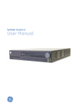
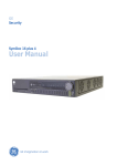
Download Video Systems DV8000 Specifications
Transcript
UTC Fire & Security
9 Farm Springs Road
Farmington, CT 06034-4065
FACILITY COMMANDER™ 2.2.3
A&E SPECIFICATIONS
APRIL 2011
DIVISION 25
INTEGRATED AUTOMATION
LEVEL 1
25 30 00
INTEGRATED AUTOMATION INSTRUMENTATION AND
TERMINAL DEVICES
LEVEL 2
25 38 00
INTEGRATED AUTOMATION INSTRUMENTATION AND
TERMINAL DEVICES FOR ELECRONIC SAFETY AND
SECURITY SYSTEMS
LEVEL 3
25 38 00
NOT APPLICABLE
LEVEL 4
25 38 00.00
NOT APPLICABLE
LEVEL 5
25 38 00.00.FCC223
FILE REFERENCE ONLY
This A&E Specification conforms to CSI MasterFormat 2004 guidelines.
The bold highlighted level above identifies the level this specification meets in the CSI MasterFormat hierarchy.
Feel free to consult with UTC Fire and Security regarding specific project requirements. For information and assistance
contact:
UTC Fire and Security
791 Park of Commerce Blvd., Suite 100
Boca Raton, FL 33487
Tel: (561) 998-6100
U.S.A. Toll Free: (800) 428-2733
Fax: (561) 994-6572
Internet: http://www.utcfireandsecurity.com
DOCUMENT NOTES
Warranty Information: Product is warranted by the manufacturer for 36 months from the date of purchase by
the dealer or integrator from the manufacturer. The warranty statement provided in Part 1 is an example of
requirements to the installing contractor and may not directly represent the product.
This document was created in Word 2007 and may lose some formatting when converted to earlier versions
or to other programs. Please review the PDF version should formatting errors appear.
To delete this cover page (Word 2007 or later):
Click the Insert tab, click Cover Page in the Pages group, and then click Remove Current Cover Page.
LENEL CONFIDENTIAL INFORMATION – For use by Lenel-authorized VARs, prospective or existing Facility Commander users
and their respective authorized consultants. All other third-party use is prohibited without Lenel’s written permission.
®
LENEL - A UTC FIRE & SECURITY COMPANY
[PROJECT NUMBER]
[DATE]
FACILITY COMMANDER™ v2.2.3 GUIDE SPECIFICATIONS
[PROJECT NAME]
[PROJECT LOCATION]
TABLE OF CONTENTS
PART 1 GENERAL .................................................................................................................................... 1
1.1
SUMMARY .................................................................................................................................... 1
1.2
REFERENCES .............................................................................................................................. 1
1.3
SUBMITTALS ................................................................................................................................ 1
1.4
CLOSE-OUT SUBMITTALS.......................................................................................................... 1
1.5
WARRANTY .................................................................................................................................. 2
PART 2 PRODUCTS ................................................................................................................................. 3
2.1
OWNER FURNISHED EQUIPMENT ............................................................................................ 3
2.2
SYSTEM........................................................................................................................................ 5
2.3
PERFORMANCE CRITERIA ........................................................................................................ 5
PART 3 EXECUTION .............................................................................................................................. 18
3.1
INSTALLERS .............................................................................................................................. 18
3.2
EXAMINATION............................................................................................................................ 18
3.3
PREPARATION........................................................................................................................... 18
3.4
INSTALLATION ........................................................................................................................... 18
3.5
QUALITY CONTROL .................................................................................................................. 19
3.6
SYSTEM STARTUP .................................................................................................................... 19
3.7
CLOSEOUT ACTIVITIES ............................................................................................................ 20
LENEL CONFIDENTIAL INFORMATION – For use by Lenel-authorized VARs, prospective or existing Facility Commander users
and their respective authorized consultants. All other third-party use is prohibited without Lenel’s written permission.
®
LENEL - A UTC FIRE & SECURITY COMPANY
[PROJECT NUMBER]
[DATE]
FACILITY COMMANDER™ v2.2.3 GUIDE SPECIFICATIONS
[PROJECT NAME]
[PROJECT LOCATION]
SECTION 25 38 00
PART 1 GENERAL
1.1
1.2
SUMMARY
A.
Section Includes
1.
Security Integration Command and Control Platform Performance Requirements
B.
Related Requirements
1.
Integrated Systems and Options
a.
27 51 23 Intercommunication and Program Systems
b.
28 13 00 Access Control
c.
28 20 00 Electronic Surveillance
d.
28 30 00 Electronic Detection of Alarms
2.
Related Sections
a.
26 33 53 Static Uninterruptible Power Supply
b.
27 20 00 Data Communications
REFERENCES
A.
B.
C.
D.
E.
F.
1.3
SUBMITTALS
A.
B.
C.
D.
1.4
NFPA 70 - National Electrical Code.
NFPA 101 - Life Safety Code.
UL 294 - Access Control Systems.
UL 1076 - Proprietary Burglar Alarm Units and Systems.
Americans with Disabilities Act - Public Law 101.336.
FCC.
Single-line block diagram showing all related equipment interfaces.
Manufacturer technical data sheets.
Shop Drawings.
Software: 1 set of fully functional software in manufacturer’s original media packaging,
temporarily licensed for a (30) day evaluation period.
CLOSE-OUT SUBMITTALS
A.
B.
C.
D.
E.
F.
G.
H.
I.
J.
Maintenance Contracts
Operation and Maintenance Data/Manuals
Warranty Documentation
Record Documentation
Software
Commissioning Documentation and Check-Off List
As-Built Drawings
Training Course Materials
Training Presentations
Training Class Video Files
[AUTHOR]
[FILE NAME]
INTEGRATED AUTOMATION INSTRUMENTATION & TERMINAL
DEVICES FOR ELECTRONIC SAFETY & SECURITY SYSTEMS
25 38 00 - 1
LENEL CONFIDENTIAL INFORMATION – For use by Lenel-authorized VARs, prospective or existing Facility Commander users
and their respective authorized consultants. All other third-party use is prohibited without Lenel’s written permission.
®
LENEL - A UTC FIRE & SECURITY COMPANY
[PROJECT NUMBER]
[DATE]
1.5
FACILITY COMMANDER™ v2.2.3 GUIDE SPECIFICATIONS
[PROJECT NAME]
[PROJECT LOCATION]
WARRANTY
A.
Warranty
1.
Warrant system against defects and workmanship for minimum of (12) months, covering
all parts and labor, after Owner acceptance.
2.
Guarantee all application software/firmware remains current at all times.
3.
Guarantee all application software/firmware is manufacturer supported.
4.
Perform all manufacturer recommended preventative maintenance on all related
components and/or devices.
5.
The Security Contractor shall be the primary contact and respondent for all service and
support and officially recognized and backed by the system manufacturer.
B.
Extended Correction Period
1.
Guarantee all system corrections for six (6) months after Owner acceptance.
C.
Special Warranty
1.
Provide a separate proposal for extended warranty and maintenance service contract for
Owner consideration.
2.
One (1) year agreement.
3.
Discount levels for three (3) and five (5) year agreement.
4.
Submit payment terms and conditions with proposal.
[AUTHOR]
[FILE NAME]
INTEGRATED AUTOMATION INSTRUMENTATION & TERMINAL
DEVICES FOR ELECTRONIC SAFETY & SECURITY SYSTEMS
25 38 00 - 2
LENEL CONFIDENTIAL INFORMATION – For use by Lenel-authorized VARs, prospective or existing Facility Commander users
and their respective authorized consultants. All other third-party use is prohibited without Lenel’s written permission.
®
LENEL - A UTC FIRE & SECURITY COMPANY
[PROJECT NUMBER]
[DATE]
FACILITY COMMANDER™ v2.2.3 GUIDE SPECIFICATIONS
[PROJECT NAME]
[PROJECT LOCATION]
PART 2 PRODUCTS
2.1
OWNER FURNISHED EQUIPMENT
A.
Host Server
***RECOMMENDED Windows/Linux***
1.
Intel CISC Based Server
a.
Dell PowerEdge 510/610/710 Server
b.
2 x Intel Xeon Quad Core E5504 CPUs
c.
4 GB RAM
d.
4 x 146 GB 15K RPM SAS Disk Drives with RAID1 or RAID10
e.
1 Gbit Network Interface Card (NIC)
f.
DVD-ROM Optical Drive
g.
Graphical Monitor and Video Card
h.
Keyboard and Mouse
i.
DAT72 Tape Backup Device with external SCSI Controller (Optional)
***MINIMUM Windows/Linux***
1.
Intel CISC Based Server
a.
Dell PowerEdge 2900/2950 Server
b.
Intel Xeon Quad Core E5310 CPU
c.
4 GB RAM
d.
2 x 73 GB 15K RPM SAS or SCSI Disk Drives (RAID Optional)
e.
100 Mbit Network Interface Card (NIC)
f.
DVD-ROM Optical Drive
g.
Graphical Monitor and Video Card
h.
Keyboard and Mouse
i.
DAT72 Tape Drive Backup Device (Optional)
***RECOMMENDED AIX***
1.
IBM RISC Based Server
a.
IBM P6 Series Model 520
b.
4.2 GHz Quad Core CPU
c.
8 GB RAM
d.
4 x 146 GB 15K RPM SAS Disk Drives with RAID1 or RAID 10
e.
1 Gbit Network Interface Card (NIC)
f.
DVD-ROM Optical Drive
g.
Graphical Monitor and Video Card
h.
Keyboard and Mouse
i.
DAT72 Tape Backup Device with external SCSI Controller (Optional)
***MINIMUM AIX***
1.
IBM RISC Based Server
a.
IBM P5 Series Model 520
b.
Dual Core CPU
c.
4 GB RAM
d.
4 x 73 GB 15K RPM SAS or SCSI Disk Drives (RAID Optional)
e.
100 Mbit Network Interface Card (NIC)
f.
DVD-ROM Optical Drive
g.
Graphical Monitor and Video Card
h.
Keyboard and Mouse
i.
DAT72 Tape Drive Backup Device (Optional)
B.
Remote Media Server
1.
Dell PowerEdge T100 or R200 Server
2.
Single Xeon E3110, 3.0 GHz, 6 MB Cache
[AUTHOR]
[FILE NAME]
INTEGRATED AUTOMATION INSTRUMENTATION & TERMINAL
DEVICES FOR ELECTRONIC SAFETY & SECURITY SYSTEMS
25 38 00 - 3
LENEL CONFIDENTIAL INFORMATION – For use by Lenel-authorized VARs, prospective or existing Facility Commander users
and their respective authorized consultants. All other third-party use is prohibited without Lenel’s written permission.
®
LENEL - A UTC FIRE & SECURITY COMPANY
[PROJECT NUMBER]
[DATE]
3.
4.
5.
6.
7.
8.
9.
10.
FACILITY COMMANDER™ v2.2.3 GUIDE SPECIFICATIONS
[PROJECT NAME]
[PROJECT LOCATION]
4 GB RAM
160 GB 7.2K RPM Hard Drive
1 Gbit Network Interface Card (NIC)
56K Modem
DVD-ROM Optical Drive
Redundant Power Supplies
Graphical Monitor and Video Card
Keyboard and Mouse
C.
Web Browser, Client Workstation
***RECOMMENDED ***
1.
Dell Precision T3500 Workstation
2.
Xeon E5506, 2.13 GHz, 4MB Cache
3.
3 GB RAM
4.
160 GB 7.2K RPM Hard Drive
5.
1 Gbit Network Interface Card (NIC)
6.
56K Modem
7.
DVD-ROM Optical Drive
8.
Graphical Monitor
9.
Video: Graphics card hardware support for DirectX 9 with Pixel Shader 3
10.
Keyboard and Mouse
***MINIMUM ***
1.
Dell OptiPlex 760 Minitower Workstation
2.
Core 2 Duo E8400, 2.93 GHz, 6MB Cache
3.
2 GB RAM
4.
80 GB 3 Gbit/sec Hard Drive
5.
1 Gbit Network Interface Card (NIC)
6.
56K Modem
7.
DVD-ROM Optical Drive
8.
Graphical Monitor
9.
Video: Graphics card hardware support for DirectX 9 with Pixel Shader 3
10.
Keyboard and Mouse
D.
Host Server Software
1.
Windows
a.
Operating System: Windows Server 2008
b.
Database: Microsoft SQL Server 2008
2.
Linux
a.
Operating System: Red Hat Linux 5.3 (32-bit)
b.
Database: Informix 11.5 UC3
3.
AIX
a.
Operating System: AIX 6.1 (64-bit)
b.
Database: Informix 11.5 UC3
E.
Remote Media Server Software
1.
Windows
a.
Operating System: Windows Server 2008, Windows Server 2003 SP2, or
Windows Server 2003 R2, Windows XP Professional SP3
2.
Linux
a.
Operating System: Red Hat Linux 5.3 (32-bit)
F.
Web Browser, Client Workstation Software
1.
Operating System: Microsoft Windows XP Professional SP3, Windows Vista SP2,
Windows 7 (32-bit)
[AUTHOR]
[FILE NAME]
INTEGRATED AUTOMATION INSTRUMENTATION & TERMINAL
DEVICES FOR ELECTRONIC SAFETY & SECURITY SYSTEMS
25 38 00 - 4
LENEL CONFIDENTIAL INFORMATION – For use by Lenel-authorized VARs, prospective or existing Facility Commander users
and their respective authorized consultants. All other third-party use is prohibited without Lenel’s written permission.
®
LENEL - A UTC FIRE & SECURITY COMPANY
[PROJECT NUMBER]
[DATE]
2.
3.
2.2
2.3
FACILITY COMMANDER™ v2.2.3 GUIDE SPECIFICATIONS
[PROJECT NAME]
[PROJECT LOCATION]
Web Browser: Microsoft Internet Explorer 6.0 SP1, Internet Explorer 7.0, Internet
Explorer 8.0 (required for Windows 7), or Mozilla Firefox 3.0
Other: Adobe Acrobat Reader
SYSTEM
A.
Manufacturer
1.
Provide all system software as a standard catalog product offering of a single
manufacturer.
2.
Exception: Servers, workstations, and related computing peripherals shall be specified
characteristics that are in regular production by an industry recognized computer
manufacturer, provided that replaceable components are available from multiple third
party sources.
3.
This specification is based on Facility Commander 2.2.3 software manufactured by UTC
Fire and Security; 791 Park of Commerce Boulevard, Boca Raton, FL 33487 USA. Tel:
(561) 998-6100. Fax: (561) 994-6572 www.utcfireandsecurity.com.
B.
Description
1.
The system provides command and control of video, access control, intercom, and
intrusion devices from a single intuitive console.
2.
Installed system server software.
3.
Installed remote server software.
4.
Installed client workstation software.
5.
Integration to related software and hardware.
6.
Setup and configure communication among the host server, remote servers, subsystems,
and operator workstations.
7.
Setup and configuration of system application and database.
8.
Setup and configuration of graphical user interfaces and graphic maps.
PERFORMANCE CRITERIA
A.
System Architecture:
1.
Scalable application platform consolidates capabilities for multiple security-related
systems
a.
Access control systems
b.
Digital video systems
c.
Analog video camera switchers
d.
Intrusion systems
e.
Intercom systems
2.
System Server
a.
Open architecture system operational on commercial off-the-shelf operating
systems: Windows, Linux, and AIX.
b.
Web enabled and network enabled system server.
c.
Permit multiple users simultaneous configure and monitor rights.
d.
Allows a choice of subsystems to be monitored and controlled through one screen.
e.
System server database shall be in concert with the operating system.
f.
Co-residency.
1)
Allow co-residency of Linux version of software with access control system.
(a)
Specific to Linux version of Picture Perfect 4.5.1.
(b)
Allow sharing of single Informix database.
3.
Remote Servers
a.
Intel based computer platforms operational on either Windows or Linux operating
system.
b.
Interface with the system server.
[AUTHOR]
[FILE NAME]
INTEGRATED AUTOMATION INSTRUMENTATION & TERMINAL
DEVICES FOR ELECTRONIC SAFETY & SECURITY SYSTEMS
25 38 00 - 5
LENEL CONFIDENTIAL INFORMATION – For use by Lenel-authorized VARs, prospective or existing Facility Commander users
and their respective authorized consultants. All other third-party use is prohibited without Lenel’s written permission.
®
LENEL - A UTC FIRE & SECURITY COMPANY
[PROJECT NUMBER]
[DATE]
FACILITY COMMANDER™ v2.2.3 GUIDE SPECIFICATIONS
[PROJECT NAME]
[PROJECT LOCATION]
c.
d.
4.
5.
6.
7.
8.
9.
B.
Satisfy requests from the system server for video tagging and video playback.
Communicate with the System Server using industry standard communication
protocols.
e.
Communicate automatically upon configuration in the system server.
f.
Remote servers shall not require a database or system backup.
Web Browser Client
a.
Intel based client operational on Windows operating system.
b.
The Web browser client shall not require additional client software.
c.
Microsoft Internet Explorer version 6 or higher.
d.
All communication with the system server shall be encrypted using industry
standard methods.
e.
All system configuration and reporting shall be performed using the Web browser
client.
Command and Control Client
a.
Intel based client operational on Windows operating system.
b.
All communication with the command and control client shall be encrypted using
industry standard methods.
c.
Client software shall be downloadable from the system server over the intranet.
d.
The system server shall only communicate with specifically identified command and
control clients.
Standard TCP/IP network communication protocol between servers and client
workstations.
Ethernet connectivity over LAN/WAN network typologies.
The system shall support SSL encryption for all HTML and XML-RPC communication
links.
Flexible and scalable architecture, permitting expansion of both capacity and functionality
with software licensing and/or software upgrades.
System Functions
1.
Monitor and display card access, video, intercom, intrusion detection, and alarm activity.
2.
Manage interfaces between subsystems and coordinate input and outputs to engage
same system or ‘other’ system actions.
3.
Visually and audibly annunciate alarms upon change of status, for assessment and
response at all operator workstations.
4.
Manage disparate video systems as a single entity.
5.
Employ distributed processing technology, allowing the host to function almost entirely as
an application/database server.
6.
Maintain system history reports.
a.
Alarms and alarm responses.
b.
System-generated events.
c.
Generated on a number of different selection and sort criteria.
7.
Remote installed reports.
a.
Allow installation of standard and history reports on Linux version of access control
system server.
b.
Specific to Linux versions of Picture Perfect 4.5.1.
c.
Standard Reports.
1)
Access Points Report.
2)
Alarm Instructions Report.
3)
Alarm Profiles Report.
4)
Cameras Report.
5)
Contexts Report.
6)
Digital Inputs Report.
7)
Digital Outputs Report.
8)
Digital Video Recorders Report.
[AUTHOR]
[FILE NAME]
INTEGRATED AUTOMATION INSTRUMENTATION & TERMINAL
DEVICES FOR ELECTRONIC SAFETY & SECURITY SYSTEMS
25 38 00 - 6
LENEL CONFIDENTIAL INFORMATION – For use by Lenel-authorized VARs, prospective or existing Facility Commander users
and their respective authorized consultants. All other third-party use is prohibited without Lenel’s written permission.
®
LENEL - A UTC FIRE & SECURITY COMPANY
[PROJECT NUMBER]
[DATE]
d.
FACILITY COMMANDER™ v2.2.3 GUIDE SPECIFICATIONS
[PROJECT NAME]
[PROJECT LOCATION]
9)
Facilities Report.
10) Facility Memberships Report.
11) Logical Inputs Report.
12) Operators Report.
13) Servers Report.
14) Workstations Report.
History Reports.
1)
Alarm History Report.
2)
Events Report.
3)
Intercom Events History Report.
4)
Intrusion Events History Report.
5)
MEA Audit Events History Report.
6)
Media Actions Events History Report.
7)
Table Rollover Events History Report.
8)
Operator History Report.
C.
System Capacity:
1.
Support the following capacities:
a.
254 remote servers
b.
4,096 cameras
c.
10,000 client stations
d.
500 alarm priority levels
e.
Unrestricted number of graphical maps
1)
Unrestricted number of map layers
2)
Unrestricted number of symbols per map
f.
Centrally store a minimum of 1,000,000 historical events (transactions) on-line
2.
Remote servers shall support an unrestricted number of video recorders
D.
Operator Interface:
1.
General
a.
Provide for separate client applications for system configuration and control
operations
1)
Web browser
(a)
Define and configure all devices and components used in the system
(b)
Generate system reports
2)
Command and control client
(a)
Monitor all events in the system in real-time
(b)
Acknowledge alarms
(c)
View video
(d)
Control devices
b.
Access shall be by authorized log-in, requiring a unique log-in name and valid
password
c.
Access to each function of the system configuration and Command and Control
client application shall be controlled by operator permissions
1)
Permissions shall be controllable on five levels: execute, view, update,
create, and delete
2)
Default system permission records shall be provided for ease-of-use in
administration
3)
No limit to the number of permissions defined
4)
No limit to the number of operators defined
d.
Implement National Language Support (NLS) allowing simultaneous multi-lingual
operation
1)
Language selection per individual operator language preference
[AUTHOR]
[FILE NAME]
INTEGRATED AUTOMATION INSTRUMENTATION & TERMINAL
DEVICES FOR ELECTRONIC SAFETY & SECURITY SYSTEMS
25 38 00 - 7
LENEL CONFIDENTIAL INFORMATION – For use by Lenel-authorized VARs, prospective or existing Facility Commander users
and their respective authorized consultants. All other third-party use is prohibited without Lenel’s written permission.
®
LENEL - A UTC FIRE & SECURITY COMPANY
[PROJECT NUMBER]
[DATE]
FACILITY COMMANDER™ v2.2.3 GUIDE SPECIFICATIONS
[PROJECT NAME]
[PROJECT LOCATION]
2)
2.
3.
[AUTHOR]
[FILE NAME]
Graphical user interface shall be English and [Spanish] [French]
[Portuguese] [Dutch] [Italian] [German] [Russian] [Arabic] [Korean]
[Japanese] [Chinese Simplified] [Chinese Traditional]
Web Browser Client
a.
System Configuration
1)
Define and configure devices
2)
Define event to action mappings
3)
Identify device events in any subsystem to trigger single/multiple actions in
all other subsystems
4)
The integration platform shall extract data from subsystem databases
whenever possible, eliminating repeat data entry
b.
Reports for system configuration and transaction history data shall be accessed
through the browser interface
c.
Administration Features
1)
Create facilities
(a)
Define each device to be a member of one or more facilities
2)
Assign operator facilities
(a)
Assign one or more assigned facilities
(b)
Operators shall be able to work simultaneously in all of their assigned
facilities
3)
Define operator permissions
(a)
Operator action limited by the permission profile for the operator in a
particular facility
(b)
Ability to add, modify or delete devices and other records (such as
servers, workstations, and operators) based on permissions
4)
The system shall have a documented System Backup and Recovery
procedure
Command and Control Client
a.
General
1)
Log-in sessions shall carry the facilities and permissions associated with the
operator.
2)
Valid log-in shall activate client launcher, from which the individual
applications can be run.
3)
Allow multiple instances of each application to be launched.
4)
Provide a facility filter mechanism allowing operators to filter the facilities "in
play."
(a)
Allow facility filtering per instance.
5)
Allow user-named filtered window applications.
(a)
Re-launch user-named filtered window applications on request.
6)
Provide window size and position memory for each instance of each
application window.
b.
Symbol Editor
1)
Provide a tool to associate symbols to devices for use with graphical maps.
(a)
System shall provide a series of default graphic images.
(b)
System shall support the use of customized graphic images that are in
JPG, GIF, or animated GIF formats.
(c)
Variable sizes shall be supported: 16x16, 24x24, or 32x32 pixels.
2)
Link different graphic images (icons) with devices types, such as:
(a)
Access points.
(b)
Camera types.
(c)
Digital inputs.
(d)
Logical inputs.
(e)
Digital outputs.
(f)
Intercom stations.
INTEGRATED AUTOMATION INSTRUMENTATION & TERMINAL
DEVICES FOR ELECTRONIC SAFETY & SECURITY SYSTEMS
25 38 00 - 8
LENEL CONFIDENTIAL INFORMATION – For use by Lenel-authorized VARs, prospective or existing Facility Commander users
and their respective authorized consultants. All other third-party use is prohibited without Lenel’s written permission.
®
LENEL - A UTC FIRE & SECURITY COMPANY
[PROJECT NUMBER]
[DATE]
3)
[AUTHOR]
[FILE NAME]
FACILITY COMMANDER™ v2.2.3 GUIDE SPECIFICATIONS
[PROJECT NAME]
[PROJECT LOCATION]
(g)
Intrusion devices.
Develop symbol schemes to correlate device attributes and conditions.
(a)
Device attributes represent the type of alarm generated.
(1)
Door Access Point.
(i)
Initial State.
(ii)
Door Forced.
(iii)
Door Held.
(iv)
Door Pre-alarm.
(v)
Invalid Badge Alarm.
(vi)
Lost Badge Alarm.
(vii) Suspended Badge Alarm.
(viii) Unknown Badge Alarm.
(2)
Camera.
(i)
Initial State.
(ii)
Motion Detection.
(iii)
Video Loss.
(3)
Logical Input.
(i)
Initial State.
(ii)
Input Alarm.
(4)
Digital Input.
(i)
Initial State.
(ii)
Input Alarm.
(5)
Digital Output.
(i)
Initial State.
(6)
Intercom Exchange.
(i)
Initial State.
(ii)
Communication Failure.
(iii)
Reset.
(7)
Intercom Master Station.
(i)
Initial State.
(ii)
Busy.
(iii)
Call Answered.
(iv)
Call Connected.
(v)
Call Ringing.
(vi)
Call To Busy.
(vii) Call to Private.
(viii) Disconnected.
(ix) Reset.
(8)
Intercom Substation.
(i)
Initial State.
(ii)
Busy.
(iii)
Call Answered.
(iv)
Call Button Alarm.
(v)
Call Button Event.
(vi)
Call Connected.
(vii) Call Ringing.
(viii) Call To Busy.
(ix) Call to Private.
(x)
Disconnected.
(xi) Reset.
(9)
Intrusion Area.
(i)
Initial State.
(ii)
Armed All Clear.
(iii)
Armed and in Alarm.
INTEGRATED AUTOMATION INSTRUMENTATION & TERMINAL
DEVICES FOR ELECTRONIC SAFETY & SECURITY SYSTEMS
25 38 00 - 9
LENEL CONFIDENTIAL INFORMATION – For use by Lenel-authorized VARs, prospective or existing Facility Commander users
and their respective authorized consultants. All other third-party use is prohibited without Lenel’s written permission.
®
LENEL - A UTC FIRE & SECURITY COMPANY
[PROJECT NUMBER]
[DATE]
c.
[AUTHOR]
[FILE NAME]
FACILITY COMMANDER™ v2.2.3 GUIDE SPECIFICATIONS
[PROJECT NAME]
[PROJECT LOCATION]
(iv)
Disarmed.
(v)
Unknown.
(10) Intrusion DGP.
(i)
Initial State.
(ii)
Bypassed.
(iii)
Offline Alarm.
(iv)
Tamper Alarm.
(v)
Main Power Failure Alarm.
(11) Intrusion Input.
(i)
Initial State.
(ii)
Alarm.
(iii)
Alarm Event.
(iv)
Bypassed.
(v)
Tamper.
(12) Intrusion Keypad.
(i)
Initial State.
(ii)
Duress Alarm.
(iii)
Bypassed.
(iv)
Offline.
(v)
Tamper.
(13) Intrusion Panel.
(i)
Initial State.
(ii)
Duress Code Entered Alarm.
(iii)
Offline Alarm.
(iv)
Tamper Alarm.
(14) Monitor.
(i)
Initial State.
(b)
Device conditions represent the state of the alarm point.
(1)
Set.
(2)
Reset.
(3)
Tamper.
4)
Initial state icons shall indicate that there are no pending alarms for the
device.
Graphics Editor
1)
Provide a tool to create graphic representations of facilities, system devices
and alarm conditions.
(a)
Allow development of multiple layers within map drawings.
(1)
Define map layers that can be turned on or off for viewing.
(2)
Permit development of hierarchical arrangements associating
several levels of graphic maps.
(b)
Allow commands to be issued from the graphic display.
(1)
Provide and define hyperlinks that allow operators to traverse
through a series of maps.
(2)
Select device icons from a device palette containing all userdefined symbols in the system.
(3)
Link device symbols to devices in the system database.
(c)
Allow the user to update the symbols or the maps as desired.
2)
Provide a tool to create base graphical maps.
(a)
Draw graphic maps using on board drawing tools.
(b)
Import JPG or GIF format graphic files.
(c)
Import DXF R12 CAD drawings.
(1)
Allow import of two-dimensional drawings.
(2)
Allow import of drawings as a single object.
(3)
Allow import of selected layers from a drawing.
INTEGRATED AUTOMATION INSTRUMENTATION & TERMINAL
DEVICES FOR ELECTRONIC SAFETY & SECURITY SYSTEMS
25 38 00 - 10
LENEL CONFIDENTIAL INFORMATION – For use by Lenel-authorized VARs, prospective or existing Facility Commander users
and their respective authorized consultants. All other third-party use is prohibited without Lenel’s written permission.
®
LENEL - A UTC FIRE & SECURITY COMPANY
[PROJECT NUMBER]
[DATE]
FACILITY COMMANDER™ v2.2.3 GUIDE SPECIFICATIONS
[PROJECT NAME]
[PROJECT LOCATION]
(4)
(5)
d.
e.
[AUTHOR]
[FILE NAME]
Allow imported layers to be deleted.
Permit the re-import of a DXF file, without consequence to
symbols previously place on the graphic display and linked to
database objects.
3)
Associate symbol schemes with access points and device types.
Alarm Monitor
1)
Display all active alarms real time in priority order.
2)
Provide alarm management features for alarm acknowledgement.
3)
Permit choice of time zone view from one or more time zone options.
(a)
Local device time.
(b)
Operator time.
(c)
Server time.
(d)
GMT.
(e)
Display any or all combinations of time zones simultaneously.
4)
Provide simple access to video clips and graphical maps associated with the
alarm.
(a)
Display recorded video and live video simultaneously.
5)
Display alarms from all system and subsystem sources:
(a)
Primary system.
(b)
Access Control Subsystem.
(c)
Intercom Subsystem.
(d)
Intrusion Subsystem.
(e)
Digital Video Subsystem.
(f)
Maintain complete synchronization between the primary system and
access control subsystem alarm monitors.
6)
Display detail for each alarm.
(a)
Video clip indicators.
(b)
Graphical map indicators.
(c)
Date and time.
(d)
Alarm description.
(e)
Location.
(f)
Alarm state.
(g)
Input state.
(h)
Processing state.
(i)
Count.
7)
User acknowledged alarms.
(a)
Enter free-form response text.
(b)
Select from a list of predefined responses.
(c)
Permit an unlimited number of responses per alarm event.
8)
Display up to five (5) user-definable instructions per alarm.
9)
Notify personnel automatically of alarms using email or other SNMP-enabled
devices.
Event Monitor
1)
Display alarm, badge, and system events real time in chronological order.
2)
Permit choice of time zone view from one or more time zone options.
(a)
Local device time.
(b)
Operator time.
(c)
Server time.
(d)
GMT.
(e)
Display any or all combinations of time zones simultaneously.
3)
Allow operator to freeze the screen view.
4)
Display detail for each event.
(a)
Type.
(b)
Description.
INTEGRATED AUTOMATION INSTRUMENTATION & TERMINAL
DEVICES FOR ELECTRONIC SAFETY & SECURITY SYSTEMS
25 38 00 - 11
LENEL CONFIDENTIAL INFORMATION – For use by Lenel-authorized VARs, prospective or existing Facility Commander users
and their respective authorized consultants. All other third-party use is prohibited without Lenel’s written permission.
®
LENEL - A UTC FIRE & SECURITY COMPANY
[PROJECT NUMBER]
[DATE]
f.
[AUTHOR]
[FILE NAME]
FACILITY COMMANDER™ v2.2.3 GUIDE SPECIFICATIONS
[PROJECT NAME]
[PROJECT LOCATION]
(c)
Location.
(d)
Variable parameters based on event type.
5)
Provide simple access to associated video clips.
6)
Filter events by selecting the types to be viewed.
Video Viewer
1)
Allow retrieval of remote video for viewing on any workstation.
2)
Allow simultaneous viewing by multiple operators on different workstations.
(a)
View event based video clips.
(b)
View live video.
(c)
View same and different cameras.
3)
Provide recorded video controls.
(a)
Play forward.
(b)
Play reverse.
(c)
Pause.
(d)
Resume.
(e)
Stop.
(f)
Reverse.
(g)
Fast reverse.
(h)
Fast-forward.
(i)
Forward and reverse single stepping.
4)
Operator controls.
(a)
Selection of up to 32 video inputs in the same window.
(1)
Live or recorded selectable video input.
(b)
Synchronized playback of multiple cameras.
(c)
Record video of any stream locally.
(d)
Create ready to play evidence CDs.
(e)
Define custom views with a self defined layout.
(f)
Control Pan Tilt Zoom (PTZ) cameras.
(1)
Manually with on-screen mouse movements.
(2)
Automatically by directing the camera to a predefined preset
position.
(3)
Camera selection for supported cameras using Pelco KBD300A
Cam key.
(4)
PTZ operations for supported cameras using Pelco KBD300A
joystick.
(5)
Iris/Focus operations for supported cameras using Pelco
KBD300A Iris/Focus keys.
(6)
Washer/Wiper operations for supported cameras using Pelco
KBD300A Aux keys.
(7)
On-screen menu access for supported cameras using Pelco
KBD300A Preset key.
(8)
PTZ operations for supported cameras using virtual keyboard
PTZ buttons.
(9)
Iris/Focus operations for supported cameras using virtual
keyboard Iris/Focus buttons.
(10) Washer/Wiper operations for supported cameras using virtual
keyboard Aux buttons.
(11) On-screen menu access for supported cameras using virtual
keyboard Menu buttons.
5)
Video Clip Search.
(a)
Time and date.
(b)
DVR.
(c)
Camera.
(d)
Event type.
INTEGRATED AUTOMATION INSTRUMENTATION & TERMINAL
DEVICES FOR ELECTRONIC SAFETY & SECURITY SYSTEMS
25 38 00 - 12
LENEL CONFIDENTIAL INFORMATION – For use by Lenel-authorized VARs, prospective or existing Facility Commander users
and their respective authorized consultants. All other third-party use is prohibited without Lenel’s written permission.
®
LENEL - A UTC FIRE & SECURITY COMPANY
[PROJECT NUMBER]
[DATE]
FACILITY COMMANDER™ v2.2.3 GUIDE SPECIFICATIONS
[PROJECT NAME]
[PROJECT LOCATION]
(e)
Location.
Video Clip Storage.
(a)
Tag video clips automatically as a result of predefined events in the
system.
(b)
Allow any subsystem alarm or event to be linked with a video clip.
(c)
Store all video tokens in primary system database.
(d)
Each video clip shall reference the date and time of the event in the
token name.
(e)
Retrieve the video on-demand from the DVR's hard disk.
(f)
Provide a snapshot feature, allowing operator to store a single video
frame in JPG format on their local workstation disk.
Graphics Viewer
1)
Allow operators to respond to alarm events and issue commands from a
graphic representation of the facility and systems.
2)
Allow device monitoring and control using symbols on a graphical map.
3)
Control toolbar shall provide quick access actions for selected device.
4)
Limit the symbols displayed on a map based on an operator's facilities.
5)
Determine the alarm state of each device by the symbol's appearance.
(a)
Set.
(b)
Reset.
(c)
Cleared.
6)
Device symbols without associated alarms in the alarm monitor shall appear
in their initial state.
7)
Operator Controls.
(a)
Size the map as desired maintaining aspect ratio.
(b)
Dynamically select the map layers in active view.
(c)
Launch a control toolbar for any object on the graphical map.
(d)
Send device-type dependent commands.
(e)
Lock or unlock a door.
(f)
Launch live video.
(g)
Answer intercom calls.
(h)
Acknowledge alarms.
Third-Party Program Launcher.
1)
The client Launcher shall allow operators to define up to six (6) additional
third-party applications that can be launched.
2)
Customized icons can be defined for each third-party application.
6)
g.
h.
E.
System Management
1.
Configure system servers
2.
Monitor and report status and alarms
a.
Remote media server communication failure
b.
Access system communication failure
3.
Notify browser session operators of pending shutdowns upon any operator action
F.
Access Control Management:
1.
Configure to support associated access control systems
a.
Import access points
b.
Digital inputs
c.
Logical inputs
d.
Digital outputs
2.
Synchronize device information between host server and access control systems
3.
Monitor and report access status and alarms
a.
Door forced alarm
b.
Door held alarm
c.
Door pre-alarm
.
[AUTHOR]
[FILE NAME]
INTEGRATED AUTOMATION INSTRUMENTATION & TERMINAL
DEVICES FOR ELECTRONIC SAFETY & SECURITY SYSTEMS
25 38 00 - 13
LENEL CONFIDENTIAL INFORMATION – For use by Lenel-authorized VARs, prospective or existing Facility Commander users
and their respective authorized consultants. All other third-party use is prohibited without Lenel’s written permission.
®
LENEL - A UTC FIRE & SECURITY COMPANY
[PROJECT NUMBER]
[DATE]
d.
e.
f.
g.
G.
FACILITY COMMANDER™ v2.2.3 GUIDE SPECIFICATIONS
[PROJECT NAME]
[PROJECT LOCATION]
Invalid badge
Lost badge
Suspended badge
Unknown badge
Digital Video Management:
1.
Configure in accordance with client location size and geography
a.
Centralized
1)
Install media server directly on system server
2)
Single location or small site application
b.
Distributed
1)
Install remote media server
2)
Multiple locations or large site application
2.
Digital Video Recorders:
a.
Provide a fully integrated digital video recorder and camera management interface
for video command and control
b.
Support network connectivity to multiple video recorders via system host and
remote media server
c.
Provide a multi-window video management console for real time video device
monitoring and control from any operator workstation
d.
Display video recorders, cameras and assigned presets in a navigation pane for
operator access
e.
Support up to 256 video cameras per video device
f.
Support request for live and recorded video transmission from video recording units
at various resolutions and display sizes, independent of actual resolution settings
for local recorded video, user configurable to facilitate network adaptability
g.
Support setting defined preset positions for PTZ cameras
h.
Allow the assignment of video cameras and presets from subsystem alarms and
events
1)
Automatic real-time camera control
2)
Automatic live video pop-up on alarm
3)
Video event tagging
4)
Quick access to live and recorded video
i.
Provide simultaneous support for multi-vendor video drivers
j.
Monitor status and reporting alarm conditions
1)
Video Recorder
(a)
Online / Offline
(b)
Health fail
(c)
Health trouble
(d)
Disk full
2)
Camera
(a)
Analytics
(b)
Trouble
(c)
Motion detection
(d)
Video loss
k.
Support the following video recording devices:
1)
UTC Fire & Security:
(a)
DVMRe-10CD
(b)
DVMRe-10CT / StoreSafe Proc-10
(c)
DVMRe-10CT II / StoreSafe Pro II-10
(d)
DVMRe-16CD
(e)
DVMRe-16CT / StoreSafe Proc-16
(f)
DVMRe-16CT II / StoreSafe Pro II-16
(g)
DVMRe-4CD
[AUTHOR]
[FILE NAME]
INTEGRATED AUTOMATION INSTRUMENTATION & TERMINAL
DEVICES FOR ELECTRONIC SAFETY & SECURITY SYSTEMS
25 38 00 - 14
LENEL CONFIDENTIAL INFORMATION – For use by Lenel-authorized VARs, prospective or existing Facility Commander users
and their respective authorized consultants. All other third-party use is prohibited without Lenel’s written permission.
®
LENEL - A UTC FIRE & SECURITY COMPANY
[PROJECT NUMBER]
[DATE]
FACILITY COMMANDER™ v2.2.3 GUIDE SPECIFICATIONS
[PROJECT NAME]
[PROJECT LOCATION]
(h)
(i)
(j)
(k)
(l)
(m)
(n)
(o)
(p)
(q)
(r)
(s)
(t)
(u)
(v)
(w)
(x)
(y)
(z)
(aa)
(bb)
(cc)
(dd)
(ee)
(ff)
(gg)
(hh)
(ii)
(jj)
(kk)
(ll)
(mm)
l.
[AUTHOR]
[FILE NAME]
DVMRe-4CT / StoreSafe Proc-4
DVMRe-4CT II / StoreSafe Pro II-4
Kalatel DVMRe-10CT
Kalatel DVMRe-16CD
Kalatel DVMRe-16CT
Kalatel DVMRe-4CT
Kalatel StoreSafe Pro-10
Kalatel StoreSafe Pro-16
Kalatel StoreSafe Pro-4
Legend IP Dome
StoreSafe Pro II
SymDec 16
SymDec-C-16
SymDec-C-8
SymNet
SymSafe/Pro 16
SymSafe/Pro 4
SymSafe/Pro 8
SymVeo
Discovery 300, 2400 (VOS v3.x)
Discovery 2400
Discovery 300
Discovery ECVRS
Evolution 2800, 2809, ECVRS (VOS v4.x)
Evolution 28XX
Evolution HD
TruVision DVR 10 (formerly known as TruVision TVR10)
TruVision DVR 40 (formerly known as GE DVSRxU-4/8/16)
TruVision NVR40
UltraView EVP Encoder 10 (formerly known as Discovery 105E)
UltraView EVP Recorder 40 (formerly known as Discovery 1205/12X5)
UltraView EVP Recorder 60 (formerly known as Discovery
2405/2415/24X5)
(nn) UltraView EVP Recorder 80 (formerly known as Evolution 3005/30X5)
(oo) UltraView EVP NVR 80
(pp) UltraView NVR60
(qq) VisioWave
(rr)
VisioWave-4
2)
American Dynamics Intellex DVMS DV16000
3)
American Dynamics Intellex DVMS DV8000
4)
Integral Technologies DVXe, DVXi, DSXpress
5)
Integral Technologies DVXi-3.1
6)
Integral Technologies DVXi-4.0
7)
Integral Technologies DVXi-4.1
8)
NiceVision Harmony
9)
NiceVision Pro
10) Panasonic HD500A
11) Pelco DX8000
12) Pelco DX8100
13) WJ-HD500A
Support the following IP cameras (VOS dependent)
1)
UTC Fire & Security
(a)
SymVeo
(b)
Legend IP
INTEGRATED AUTOMATION INSTRUMENTATION & TERMINAL
DEVICES FOR ELECTRONIC SAFETY & SECURITY SYSTEMS
25 38 00 - 15
LENEL CONFIDENTIAL INFORMATION – For use by Lenel-authorized VARs, prospective or existing Facility Commander users
and their respective authorized consultants. All other third-party use is prohibited without Lenel’s written permission.
®
LENEL - A UTC FIRE & SECURITY COMPANY
[PROJECT NUMBER]
[DATE]
2)
3)
4)
5)
6)
7)
FACILITY COMMANDER™ v2.2.3 GUIDE SPECIFICATIONS
[PROJECT NAME]
[PROJECT LOCATION]
(c)
CamPlus IP
(d)
CamPlus IP2
Axis
ACTi
Panasonic
Pelco ExSite (Must be configured to use the Pelco D protocol and be
connected to VOS devices (Discovery 105E, 1205, 2415 or 3005) that also
support the updated protocol)
Pelco Esprit (Must be configured to use the Pelco D protocol and be
connected to VOS devices (Discovery 105E, 1205, 2415 or 3005) that also
support the updated protocol)
Pelco Dome Spectra IV (Must be configured to use the Pelco D protocol and
be connected to VOS devices (Discovery 105E, 1205, 2415 or 3005) that
also support the updated protocol)
H.
Intercom Management:
1.
Support network connectivity to multiple intercom exchanges
2.
Allow operators to connect calls from substations to master stations
3.
Allow operators to view intercom call station events on graphic displays
4.
Configure to support associated intercom systems
a.
Intercom Exchange
b.
Intercom Stations
1)
Master station
2)
Sub station
5.
Monitor and report device status and alarms
a.
Intercom Master Station
1)
Busy
2)
Call answered
3)
Call connected
4)
Call ringing
5)
Call to busy
6)
Call to private
7)
Disconnected
8)
Reset
b.
Intercom Substation
1)
Busy
2)
Call answered
3)
Call connected
4)
Call ringing
5)
Call to busy
6)
Call to private
7)
Disconnected
8)
Reset
6.
Support the following intercom systems
a.
Zenitel Stentofon AlphaCom
I.
Intrusion System Management
1.
Support network connectivity to view intrusion detection areas
a.
Locate on subnets that permit UDP/IP packet exchange
2.
Configure to support associated intrusion system
a.
Intrusion detection panels
b.
Intrusion detection data gathering panels
c.
Keypads
d.
Intrusion areas
e.
Inputs
[AUTHOR]
[FILE NAME]
INTEGRATED AUTOMATION INSTRUMENTATION & TERMINAL
DEVICES FOR ELECTRONIC SAFETY & SECURITY SYSTEMS
25 38 00 - 16
LENEL CONFIDENTIAL INFORMATION – For use by Lenel-authorized VARs, prospective or existing Facility Commander users
and their respective authorized consultants. All other third-party use is prohibited without Lenel’s written permission.
®
LENEL - A UTC FIRE & SECURITY COMPANY
[PROJECT NUMBER]
[DATE]
3.
4.
J.
FACILITY COMMANDER™ v2.2.3 GUIDE SPECIFICATIONS
[PROJECT NAME]
[PROJECT LOCATION]
f.
Outputs
g.
Allow assignment to one or multiple facilities
Monitor and report alarm conditions:
a.
Intrusion Detection Panel
1)
Duress code entered
2)
Main power failure
3)
Panel offline
4)
Siren monitor failure
5)
Panel tamper
b.
Intrusion Data Gathering Panel
1)
Panel bypassed
2)
Main power failure
3)
DGP offline
4)
Siren monitor failure
5)
Panel tamper
c.
Intrusion Keypad
1)
Intrusion keypad bypassed
2)
Duress alarm
3)
Keypad offline
4)
Keypad tamper
d.
Intrusion Area
1)
Failed to arm
2)
State armed and in alarm
e.
Intrusion inputs
1)
Input alarm
2)
Input bypassed
3)
Fault alarm
4)
Tamper alarm
Support the following intrusion detection panels
a.
Interlogix Alliance ATS 20xx
b.
Interlogix Alliance ATS 30xx
c.
Interlogix Alliance ATS 40xx
Analog CCTV Switcher Management
1.
Support network connectivity to analog video switcher
2.
Configure to support associated video system
a.
Define camera inputs
b.
Define video outputs
c.
Configure system control commands
1)
Define and assign “Enable”, “Disable”, and “Camera Alarm” messages to
system alarms
3.
Support the following CCTV matrix switcher interfaces:
a.
Interlogix
1)
Crosspoint 32 (Kalatel KTD-348)
2)
Digiplex IV (Kalatel KTD-440)
b.
Pelco
c.
Bosch Allegiant
4.
Monitor and report alarm conditions:
a.
Analog switcher offline
[AUTHOR]
[FILE NAME]
INTEGRATED AUTOMATION INSTRUMENTATION & TERMINAL
DEVICES FOR ELECTRONIC SAFETY & SECURITY SYSTEMS
25 38 00 - 17
LENEL CONFIDENTIAL INFORMATION – For use by Lenel-authorized VARs, prospective or existing Facility Commander users
and their respective authorized consultants. All other third-party use is prohibited without Lenel’s written permission.
®
LENEL - A UTC FIRE & SECURITY COMPANY
[PROJECT NUMBER]
[DATE]
FACILITY COMMANDER™ v2.2.3 GUIDE SPECIFICATIONS
[PROJECT NAME]
[PROJECT LOCATION]
PART 3 EXECUTION
3.1
3.2
INSTALLERS
A.
Contractor requirements:
1.
Factory authorized representative for no less than two (2) years, recognized by the
manufacturer of the specified system
2.
Local installation and service organization
3.
Provide three (3) references (minimum) whose systems are of similar complexity
a.
Installed by this contractor in the last five (5) years
b.
Presently maintained by the this contractor
4.
Provide satisfactory evidence of liability insurance and Workmen's Compensation
coverage for employed personnel as required by law
B.
Assure that all personnel working on the project are registered with the state or local jurisdiction
licensing board as provided for by current state/municipal statutes.
1.
At time of bid, the contractor shall be licensed by the state or local jurisdiction to perform
security work within the state.
2.
Contractors who have security licenses or permits pending shall not be considered
acceptable for bidding on this project.
C.
Installer and technician requirements:
1.
Must be experienced and qualified to accomplish all work promptly and satisfactorily.
2.
Provide proof that designated service and support personnel have successfully completed
the appropriate manufacturer offered hardware and software training and certification for
installation, service and maintenance of the specified system.
3.
Advise Owner in writing of all designated service and support personnel responsible for
installation as well as pre and post warranty service.
EXAMINATION
A.
B.
3.3
PREPARATION
A.
B.
C.
D.
E.
3.4
Inspect the installation site prior to bidding the job.
Report any discrepancies between the project specification and bid documents and the site
examination prior to the bid opening date.
Order all required parts and equipment upon notification of award.
Bench test all equipment prior to delivery to the job site.
Verify the availability of power where required. If a new source of power is required, a licensed
electrician shall be used to install it.
Verify the availability of communication infrastructure where required.
Arrange for obtaining all programming information including access times, free access times,
door groups, operator levels, etc.
INSTALLATION
A.
Requirements
1.
Install all system components and appurtenances in accordance with the manufacturer’s
specifications, referenced practices, guidelines, and applicable codes.
2.
Furnish all necessary interconnections, services, and adjustments required for a complete
and operable system as specified.
[AUTHOR]
[FILE NAME]
INTEGRATED AUTOMATION INSTRUMENTATION & TERMINAL
DEVICES FOR ELECTRONIC SAFETY & SECURITY SYSTEMS
25 38 00 - 18
LENEL CONFIDENTIAL INFORMATION – For use by Lenel-authorized VARs, prospective or existing Facility Commander users
and their respective authorized consultants. All other third-party use is prohibited without Lenel’s written permission.
®
LENEL - A UTC FIRE & SECURITY COMPANY
[PROJECT NUMBER]
[DATE]
FACILITY COMMANDER™ v2.2.3 GUIDE SPECIFICATIONS
[PROJECT NAME]
[PROJECT LOCATION]
3.
B.
3.5
3.6
Control signal, communications, and data transmission line grounding shall be installed as
necessary to preclude ground loops, noise, and surges from adversely affecting system
operation.
4.
Carefully follow the instructions in the manufacturers’ installation manual to ensure all
steps have been taken to provide a reliable, easy to operate system.
5.
Perform all Work as indicated in the project specifications and bid documents.
6.
Pre-program system and load to Owner’s host computer.
Systems Integration
1.
Coordinate with the Owner’s IT Department prior to connecting to the Owner’s network.
2.
Work in harmony with all other trades.
3.
Integrate related system and sub-systems.
QUALITY CONTROL
A.
Workmanship
1.
Comply with highest industry standards, except when specified requirements indicate
more rigid standards or more precise workmanship.
2.
Perform work with persons experienced and qualified to produce workmanship specified.
3.
Maintain quality control over suppliers and subcontractors.
4.
Quality of workmanship is considered important. Owner’s Representative will have the
authority to reject work which does not conform to the project documents.
B.
Site Tests and Inspections
1.
Execute adequate testing of the system to insure proper operation.
2.
Upon reaching Substantial Completion, perform a complete test and inspection of the
system. If found to be installed and operating properly, notify [Client] of your readiness to
perform the formal Test and Inspection of the complete system.
3.
Submit the Record Drawings (as-built) to Owner’s Representative for review prior to
inspection.
4.
During the formal Test and Inspection (Commissioning) of the system, have personnel
available with tools and equipment to remove devices from their mounts to inspect wiring
connections. Provide wiring diagrams and labeling charts to properly identify all wiring.
5.
If corrections are needed, the contractor will be provided with a Punch-List of all
discrepancies. Perform the needed corrections in a timely fashion.
6.
Notify Owner when ready to perform a re-inspection of the installation.
C.
Software Engineering Support
1.
Provide software engineer services to assist the Owner in coordinating the interfaces
between the security management system and the staff databases or other remote
systems.
2.
Software engineer shall be certified by or employed by the system manufacturer, and
shall be thoroughly knowledgeable of the system applications.
3.
Software engineer shall be on-site and available to meet with Owner’s Representatives for
a period of not less than two (2) consecutive days. On-site visit shall be scheduled at the
convenience of the Owner.
SYSTEM STARTUP
A.
B.
C.
Provide initial programming and configuration of the security management system.
Programming shall include defining hardware, doors, monitor points, clearance codes, time
codes, door groups, alarm groups, operating sequences, camera call-ups, and the like. Input of
all program data shall be by Contractor. Consult with Owner’s Representative to determine
operating parameters.
Develop and input system graphics, such as maps and standby screens.
[AUTHOR]
[FILE NAME]
INTEGRATED AUTOMATION INSTRUMENTATION & TERMINAL
DEVICES FOR ELECTRONIC SAFETY & SECURITY SYSTEMS
25 38 00 - 19
LENEL CONFIDENTIAL INFORMATION – For use by Lenel-authorized VARs, prospective or existing Facility Commander users
and their respective authorized consultants. All other third-party use is prohibited without Lenel’s written permission.
®
LENEL - A UTC FIRE & SECURITY COMPANY
[PROJECT NUMBER]
[DATE]
FACILITY COMMANDER™ v2.2.3 GUIDE SPECIFICATIONS
[PROJECT NAME]
[PROJECT LOCATION]
1.
D.
E.
F.
G.
3.7
Development of maps shall include the creation of icons for all doors, monitor points, and
tamper circuits.
2.
Owner shall provide AutoCAD .DWG or .DXF file floor plan drawings as the basis for the
creation of maps.
Owner, with the cooperation and assistance of contractor, will input the cardholder data for each
access card.
Maintain hard copy worksheets which fully document the system program and configuration.
1.
Worksheets shall be kept up to date on a daily basis until final acceptance by Owner.
2.
Worksheets shall be subject to inspection and approval by Owner.
3.
Provide final copies to Owner prior to project close-out.
Maintain a complete, up-to-date backup of the system configuration and cardholder database.
1.
Backup shall be maintained throughout programming period until final acceptance by
Owner.
2.
Submit back-up media to Owner upon Final Acceptance.
Provide follow-up assistance with system configuration sixty (60) days after start-up of system as
requested by Owner. Include a labor allowance for follow-up assistance in base bid price.
CLOSEOUT ACTIVITIES
A.
Commissioning
1.
Place entire system into full and proper operation as designed and specified.
2.
Verify that all hardware components are properly installed, connected, communicating,
and operating correctly.
3.
Verify that all system software is installed, configured, and complies with specified
functional requirements.
4.
Perform final acceptance testing in the presence of Owner’s Representative, executing a
point by point inspection against a documented test plan that demonstrates compliance
with system requirements as designed and specified.
5.
Submit documented test plan to Owner at least (14) days in advance of acceptance test,
inspection and check-off.
6.
Conduct final acceptance tests in presence of Owner’s Representative, verifying that each
device point and sequence is operating correctly and properly reporting back to control
panel and control center.
7.
Acceptance by Owner is contingent on successful completion of check-off; if check-off is
not completed due to additional work required, re-schedule and perform complete checkoff until complete in one pass, unless portions of system can be verified as not adversely
affected by additional work.
8.
System shall not be considered accepted until all acceptance test items have been
successfully checked-off. Beneficial use of part or all of the system shall not be
considered as acceptance.
B.
Training
1.
Provide system operations, administration, and maintenance training by factory trained
personnel qualified to instruct.
a.
Training shall be oriented to the specific system being installed under this contract
as designed and specified.
b.
Provide training sessions at Owner’s facility, and schedule at the Owner’s
convenience.
c.
Provide written training outline and agenda for each training session prior to
scheduling.
d.
Record and provide copies of training programs for Owner knowledgebase.
2.
Owner will designate personnel to be trained.
a.
Provide classroom instruction for people selected by Owner.
b.
Provide two (2) hours of individual hands-on training for each person.
[AUTHOR]
[FILE NAME]
INTEGRATED AUTOMATION INSTRUMENTATION & TERMINAL
DEVICES FOR ELECTRONIC SAFETY & SECURITY SYSTEMS
25 38 00 - 20
LENEL CONFIDENTIAL INFORMATION – For use by Lenel-authorized VARs, prospective or existing Facility Commander users
and their respective authorized consultants. All other third-party use is prohibited without Lenel’s written permission.
®
LENEL - A UTC FIRE & SECURITY COMPANY
[PROJECT NUMBER]
[DATE]
FACILITY COMMANDER™ v2.2.3 GUIDE SPECIFICATIONS
[PROJECT NAME]
[PROJECT LOCATION]
1)
3.
Hands-on training shall include the opportunity for each person to operate
the system.
2)
Hands-on training shall include practice of each operation that an operator
would be expected to perform.
c.
Provide printed training materials for each trainee including product manuals,
course outline, workbook or student guides, and written examinations for
certification.
Cover all operating features of the system, including the following:
a.
System set-up and cardholder database configuration.
b.
Access control features.
c.
Alarm monitoring features.
d.
Report generation and searches.
e.
Card management.
f.
Disk backup procedures.
g.
Routine maintenance and adjustment procedures.
END OF SECTION
Facility Commander v2.2.3 A&E Specification, RevA1
Copyright © 2011 Lenel Systems International, Inc. Information in this document is subject to change without
notice.
Lenel is a registered trademark of Lenel Systems International, Inc.
Microsoft and Windows are either registered trademarks or trademarks of Microsoft Corporation in the United
States and/or other countries.
Other names mentioned in this document may be trademarks or registered trademarks of their respective
owners and are hereby acknowledged.
LENEL CONFIDENTIAL INFORMATION – For use by Lenel-authorized VARs, prospective or existing
Facility Commander users and their respective authorized consultants. All other third-party use is prohibited
without Lenel’s written permission.
[AUTHOR]
[FILE NAME]
INTEGRATED AUTOMATION INSTRUMENTATION & TERMINAL
DEVICES FOR ELECTRONIC SAFETY & SECURITY SYSTEMS
25 38 00 - 21
LENEL CONFIDENTIAL INFORMATION – For use by Lenel-authorized VARs, prospective or existing Facility Commander users
and their respective authorized consultants. All other third-party use is prohibited without Lenel’s written permission.


