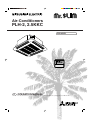
1
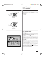
Air-Conditioners
PLH-2, 2.5KKC
FOR USER
ON/OFF –
CENTRALLY CONTROLLED
ON OFF
CHECK
CLOCK
1Hr.
˚C
FILTER
CHECK MODE
STAND BY
DEFROST
E
˚C
TEST RUN
NOT AVAILABLE
OPERATION
MANUAL
For safe and correct use, please read this operation manual thoroughly before operating the air-conditioner unit.
E
Contents
1. Safety Precautions ...................................................................... 2
1.1. Installation ..................................................................... 2
1.2. During operation ............................................................ 4
1.3. Disposing of the unit ...................................................... 5
2. Introduction ................................................................................. 6
3. Components ................................................................................ 6
3.1. Indoor unit and remote controller ................................... 6
3.2. Outdoor unit ................................................................... 7
4. Operation .................................................................................... 7
4.1. Operation modes ........................................................... 7
4.2. Switching the unit on/off ................................................ 8
4.3. Cooling .......................................................................... 8
4.4. Drying (dehumidifying) ................................................... 9
4.5. Heating .......................................................................... 9
4.6. Automatic (cooling / heating) ....................................... 10
4.7. Selecting a temperature .............................................. 10
4.8. Using the timer ............................................................ 11
4.9. Selecting a fan speed .................................................. 13
4.10.Adjusting vertical airflow direction ............................... 14
4.11.Vertical airflow adjustment ........................................... 14
5. Tips for best results ................................................................... 15
6. Care and cleaning ..................................................................... 15
6.1. Cleaning the filters and the indoor unit ........................ 15
6.2. Care and cleaning ....................................................... 16
6.3. End-of-season ............................................................. 17
6.4. Pre-season checks ...................................................... 17
7. Troubleshooting ........................................................................ 18
8. Specifications ............................................................................ 19
E
1. Safety Precautions
s Since this unit contains rotating parts and parts which
could cause an electric shock,be sure to read all of the
“Safety Precautions” before operating the unit.
s “Safety Precautions” lists important points about safety.
Please be sure to follow them.
Symbols used in the text
Warning:
Describes precautions that should be observed to avoid the risk of
injury or death to the user.
Caution:
Describes precautions that should be observed to prevent damage
to the unit.
Symbols used in the illustrations
: Indicates an action that must be avoided.
: Indicates that important instructions must be followed.
: Indicates a part which must be grounded.
: Indicates that caution should be taken with rotating parts. (This symbol is displayed on the main unit label.) <Color: Yellow>
: Indicates the main switch. (This symbol is displayed on the main
unit label.) <Color: Blue>
Warning:
Carefully read the labels affixed to the main unit.
1.1. Installation
•
•
•
•
2
Warning:
The unit should not be installed by the user. Ask the dealer or an
authorized company to install the unit. If the unit is installed improperly, water leakage, electric shock or fire may result.
Use only accessories authorized by Mitsubishi Electric and ask
your dealer or an authorized company to install them. If accessories are installed improperly, water leakage, electric shock or fire
may result.
The Installation Manual details the suggested installation method.
Any structural alteration necessary for installation must comply
with local building code requirements.
Never repair the unit or transfer it to another site by yourself. If
repair is performed improperly, water leakage, electric shock or
fire may result. If you need to have the unit repaired or moved,
consult your dealer.
E
1. Safety Precautions
1.1. Installation
1) Outdoor unit
•
•
Warning:
The outdoor unit must be installed on a stable, level surface, in a
place where there is no accumulation of snow, leaves or rubbish.
Do not stand on, or place any items on the unit. You may fall
down or the item may fall, causing injury.
Caution:
The outdoor unit should be installed in a location where air and noise
emitted by the unit will not disturb the neighbours.
2) Indoor unit
Warning:
The indoor unit should be securely installed. If the unit is loosely
mounted, it may fall, causing injury.
1.1. Installation
3) Remote controller
Warning:
The remote controller should be installed in such a way that children
cannot play with it.
4) Drain hose
Caution:
Make sure that the drain hose is installed so that drainage can go
ahead smoothly. Incorrect installation may result in water leakage,
causing damage to furniture.
3
E
1. Safety Precautions
1.1. Installation
5) Power line, fuse or circuit breaker
•
•
•
A
Warning:
Make sure that the unit is powered by a dedicated line. Other appliances connected to the same line could cause an overload.
Make sure that there is a main power switch.
Be sure to adhere to the unit’s voltage and fuse or circuit breaker
ratings. Never use a piece of wire or a fuse with a higher rating
than the one specified.
A Fuse or circuit breaker
B
B Main power switch
6) Grounding
•
•
C
Caution:
The unit must be properly grounded. Never connect the grounding wire to a gas pipe, water pipe, lightning conductor or telephone
grounding wire. If the unit is not grounded properly, electric shock
may result.
Check frequently that the ground wire from the outdoor unit is
properly connected to both the unit’s ground terminal and the
grounding electrode.
C Grounding electrode
1.2. During operation
•
MITSUBISHI
CENTRALL
Y CONTROL
ON/OFF –
LED
CHECK
ON OFF
1Hr.
CLOCK
˚C
STAND BY
DEFROST
FILTER
CHECK MODE
˚C
NOT AVAILABLE
TEST RUN
•
•
•
•
•
4
Caution:
Do not use any sharp object to push the buttons, as this may
damage the remote controller.
Do not twist or tug on the remote controller cord as this may damage the remote controller and cause malfunction.
Never block or cover the indoor or outdoor unit’s intakes or outlets. Tall items of furniture underneath the indoor unit, or bulky
items such as large boxes placed close to the outdoor unit will
reduce the unit’s efficiency.
Warning:
Do not splash water over the unit and do not touch the unit with
wet hands. An electric shock may result.
Do not spray combustible gas close to the unit. Fire may result.
Do not place a gas heater or any other open-flame appliance where
it will be exposed to the air discharged from the unit. Incomplete
combustion may result.
E
1. Safety Precautions
1.2. During operation
•
•
•
•
•
•
•
Warning:
Do not remove the front panel or the fan guard from the outdoor
unit when it is running. You could be injured if you touch rotating, hot or high-voltage parts.
Never insert fingers, sticks etc. into the intakes or outlets, otherwise injury may result, since the fan inside the unit rotates at
high speed. Exercise particular care when children are present.
If you detect odd smells, stop using the unit, turn off the power
switch and consult your dealer. Otherwise, a breakdown, electric
shock or fire may result.
Do not over-cool. The most suitable inside temperature is one
that is within 5°C of the outside temperature.
Do not leave handicapped people or infants sitting or standing in
the path of the airflow from the air-conditioner. This could cause
health problems.
Caution:
Do not direct the airflow at plants or caged pets.
Ventilate the room frequently. If the unit is operated continuously
in a closed room for a long period of time, the air will become
stale.
1.3. Disposing of the unit
Warning:
When you need to dispose of the unit, consult your dealer. If pipes
are removed incorrectly, refrigerant (fluorocarbon gas) may blow out
and come into contact with your skin, causing injury. Releasing refrigerant into the atmosphere also damages the environment.
5
E
2. Introduction
E
3. Components
This air-conditioner unit is designed for maximum efficiency and ease of
use. You can use it to cool, heat or dehumidify a room by making the
appropriate settings on the wall-mounted remote controller. Once you have
made your settings, operating the unit is usually a matter of simply pressing the POWER ON/OFF button.
The automatic cooling/heating mode allows setting of an optimum room
temperature to which the air conditioner automatically adjust the room
temperature.
s After you have read this manual, keep it and the Installation Manual
in a safe place for easy reference whenever a question arises. If
the unit is going to be operated by another person, make sure
that this manual is given to him or her.
A Indoor unit
B Remote controller
A
ON/OFF –
CENTRALLY CONTROLLED
1Hr.
ON OFF
CHECK
B
˚C
CLOCK
FILTER
CHECK MODE
STAND BY
DEFROST
˚C
TEST RUN
NOT AVAILABLE
3.1. Indoor unit and remote controller
E
The indoor unit is mounted into the ceiling of your room and puts out air
(cool, warm or dry) according to the settings you make using the remote
controller mounted on the wall.
A Air intake: Draws air in a room.
B Horizontal air outlet: To be automatically set in the horizontal blowing position in either COOL or DRY mode operation.
C Downward air outlet
F
D Automated vane: Helps circulate air upward and downward or adjusts airflow direction.
E Air filter
D
C
B
A
ON/OFF –
CENTRALLY CONTROLLED
ON OFF
CHECK
CLOCK
1Hr.
˚C
FILTER
CHECK MODE
STAND BY
DEFROST
G
6
˚C
TEST RUN
NOT AVAILABLE
F Decorative panel
G Remote controller
E
3. Components
E
4. Operation
3.2. Outdoor unit
A
The outdoor unit takes in and feeds outside air to the indoor unit and
exhausts heated air in the cooling or dehumidifying mode, or cool air in
the heating mode.
A Air outlet
B Air intake
B
PUH-2KA
A
B
PUH-2.5KA
4.1. Operation modes
Cooling
The air conditioner works to cool the room to the selected temperature.
The fan blows air continuously at the selected speed.
Drying (dehumidifying)
ing mode
ON/OFF –
CENTRALLY CONTROLLED
ON OFF
CHECK
CLOCK
1Hr.
˚C
FILTER
CHECK MODE
STAND BY
DEFROST
TEST RUN
˚C
: Disabled in the heat-
The drying mode efficiently reduces the humidity in the room so that the
room temperature is not lowered excessively. When the selected room
temperature is reached in the Low setting, the airflow will stop for ten
minutes and then will resume for three minutes to keep the humidity low.
Heating
NOT AVAILABLE
•
The air conditioner works to heat the room to the selected temperature.
•
When selecting the heating mode, a desired room temperature must
be set to avoid any cool air. The fan will gradually increase the airflow
delivery up to a selected rate.
•
When the room temperature reaches the selected temperature and
the compressor stops, the fan will deliver a gentle airflow.
CLOCK ON OFF
FILTER
CHECK
TEMP.
REMOTE CONTROLLER
PAR-JH240KA
TIMER SET
TEST RUN
Automatic (cooling / heating)
The air conditioner automatically goes into the cooling or heating mode to
keep the room at the selected temperature.
7
E
4. Operation
4.2. Switching the unit on/off
s Before pressing the ON/OFF button:
•
Check to see if the power supply is on.
•
The power supply should not be turned off while the air conditioner is
in use. This can cause the unit to break down.
1 Press the ON/OFF button.
ON/OFF –
CENTRALLY CONTROLLED
1Hr.
ON OFF
CHECK
A
˚C
CLOCK
1
FILTER
CHECK MODE
TEST RUN
˚C
STAND BY
DEFROST
NOT AVAILABLE
CLOCK ON OFF
FILTER
A The ON indicator should light up.
Note:
• Even if you press the ON/OFF button immediately after shutting
down the operation in progress, the air conditioner will not start
for about three minutes. This is to prevent the internal components from being damaged.
• If the operation stops due to a power failure, the unit will not automatically restart until the power has been restored. Press the
ON/OFF button to restart.
CHECK
TEMP.
TIMER SET
TEST RUN
REMOTE CONTROLLER
PAR-JH240KA
4.3. Cooling
1 If the unit is off, press the ON/OFF button to turn it on.
A The ON indicator should light up.
2 Press the operation mode
cooling mode
.
B
button and select the
should be displayed.
3 If necessary, press TEMP. button to set the desired temperature.
See page 10 for details.
ON/OFF –
CENTRALLY CONTROLLED
B
ON OFF
CHECK
CLOCK
FILTER
˚C
1
CHECK MODE
STAND BY
DEFROST
TEST RUN
˚C
NOT AVAILABLE
FILTER
CHECK
TIMER SET
TEST RUN
REMOTE CONTROLLER
PAR-JH240KA
26 3
8
4 If necessary, press
button to select a desired rate.
See page 13 for details.
5 If necessary, press
to specify the vertical angle at which the
air is blowing.
See page 14 for details.
6 If necessary, press
button to set the timer.
See page 11 for details.
CLOCK ON OFF
TEMP.
A
1Hr.
4 5
E
4. Operation
4.4. Drying (dehumidifying)
1 If the unit is off, press the ON/OFF button to turn it on.
A The ON indicator should light up.
2 Press the operation mode
drying mode .
B
ON/OFF –
CENTRALLY CONTROLLED
B
ON OFF
CHECK
FILTER
˚C
CLOCK
1
CHECK MODE
TEST RUN
˚C
STAND BY
DEFROST
A
1Hr.
2
CHECK
TIMER SET
TEST RUN
REMOTE CONTROLLER
PAR-JH240KA
5
3 If necessary, press TEMP. button to set the desired temperature.
See page 10 for details.
4 If necessary, press
to specify the vertical angle at which the
air is blowing.
See page 14 for details.
Note:
• When the room temperature is lower than 18°C, the drying mode
cannot be set.
• This reduces the operation level of the indoor fan.
See page 13 for details.
• There may be times when the airflow volume does not match the
display on the remote control unit.
FILTER
TEMP.
should be displayed.
5 If necessary, press
button to set the timer setting.
See page 11 for details.
NOT AVAILABLE
CLOCK ON OFF
3
button and select the
4
4.5. Heating
1 If the unit is off, press the ON/OFF button to turn it on
A The ON indicator should light up.
2 Press the operation mode
heating mode
.
B
B
ON/OFF –
CENTRALLY CONTROLLED
ON OFF
CHECK
C
D
CLOCK
FILTER
˚C
1
CHECK MODE
STAND BY
DEFROST
TEST RUN
˚C
NOT AVAILABLE
CLOCK ON OFF
FILTER
2
CHECK
3
TEMP.
A
1Hr.
TIMER SET
TEST RUN
REMOTE CONTROLLER
PAR-JH240KA
button and select the
should be displayed.
3 If necessary, press TEMP. button to set the desired temperature.
See page 10 for details.
4 If necessary, press
button to select a desired rate.
See page 13 for details.
5 If necessary, press
to specify the vertical angle at which the
air is blowing.
See page 14 for details.
6 If necessary, press
button to set the timer.
See page 11 for details.
The fan speed may differ from the set speed at the start of the heating
mode, during the defrosting mode, or after shutdown of the heating mode.
C “STAND BY” is displayed from the moment heating begins until warm air is
blown out.
D “DEFROST” is displayed during defrosting.
6
4 5
9
E
4. Operation
4.6. Automatic (cooling / heating)
The AUTO mode starts with cooling or heating depending on the current
room temperature, higher or lower, than a selected temperature value
accordingly.
1 If the unit is off, press the ON/OFF button to turn it on.
A The ON indicator should light up.
ON/OFF –
CENTRALLY CONTROLLED
FILTER
˚C
CLOCK
B
1
CHECK MODE
3 If necessary, press TEMP. button to set the desired temperature.
See page 10 for details.
4 If necessary, press
button to select a desired rate.
See page 13 for details.
NOT AVAILABLE
CLOCK ON OFF
FILTER
2
CHECK
3
should be displayed.
TEST RUN
˚C
STAND BY
DEFROST
B
button to select the
1Hr.
ON OFF
CHECK
A
2 Press the operation mode
automatic mode
.
TEMP.
TIMER SET
5 If necessary, press
to specify the vertical angle at which the
air is blowing.
See page 14 for details.
6 If necessary, press
button to set the timer.
See page 11 for details.
TEST RUN
REMOTE CONTROLLER
PAR-JH240KA
6
4 5
4.7. Selecting a temperature
TEMP.
s To decrease the room temperature:
1 Press
A
•
ON/OFF –
CENTRALLY CONTROLLED
ON OFF
CHECK
CLOCK
button to set the desired temperature.
˚C
s To increase the room temperature:
TEMP.
button to set the desired temperature.
A The selected temperature is displayed.
FILTER
TEST RUN
˚C
Each time you press the button, the temperature value decreases by
1°C.
1 Press
1Hr.
CHECK MODE
STAND BY
DEFROST
TEMP.
A The selected temperature is displayed.
•
Each time you press the button, the temperature value increases by
1°C.
•
Available temperature ranges are as follows:
NOT AVAILABLE
CLOCK ON OFF
FILTER
CHECK
1
TEMP.
REMOTE CONTROLLER
PAR-JH240KA
10
TIMER SET
TEST RUN
Cooling & Drying:
Heating:
Automatic:
Circulation:
19 - 30°C
17 - 28°C
19 - 28°C
— (Not available)
E
4. Operation
4.8. Using the timer
CLOCK
ON
OFF
s Available Timer-Interlocked Operation Modes
1. AUTO START/STOP: Allows both start and shutdown to be interlocked
with the timer.
A
2. AUTO START: Allows automatic start in response to the timer setting
and shutdown to be proceeded by manually pressing the ON/OFF button.
ON/OFF –
CENTRALLY CONTROLLED
1Hr.
ON OFF
CHECK
˚C
CLOCK
FILTER
s Timer-interlocked operation is available only once for both start
and shutdown in 24 hours.
CHECK MODE
TEST RUN
˚C
STAND BY
DEFROST
3. AUTO STOP: Allows the start of the operation to be manually invoked
by pressing the ON/OFF button and automatic shutdown based on the
timer setting.
NOT AVAILABLE
s While A
is displayed, setting and changing of time for timerinterlocked operation is disabled.
CLOCK ON OFF
FILTER
1 In this case, press
button once to turn off the A
display
on the remote controller. This is referred to as TIMER OFF operation.
CHECK
TEMP.
TIMER SET
TEST RUN
REMOTE CONTROLLER
PAR-JH240KA
1
4.8. Using the timer
CLOCK
ON
OFF
1) Set the current time
1 Press
BA
•
˚C
CLOCK
ON
OFF
CLOCK →
↑
ON
CLOCK
→
OFF
CLOCK
→ No Display
TIMER SET
NOT AVAILABLE
•
Press and hold the button to rapidly change the time.
•
The time changes in increments of one minute → ten minutes → in
units of hour; in this order.
•
Approximately ten seconds after pressing the button, the display on
the remote controller will turn off.
CLOCK ON OFF
FILTER
1
CHECK
TEMP.
CLOCK
TIMER SET
TEST RUN
˚C
button to display the “CLOCK” B.
Each time you press
button, the display on the remote controller cyclically changes as follows.
2 Each time you press
button, the time increases in increments of one minute. Each time you press
button, the time
decreases in increments of one minute .
FILTER
CHECK MODE
STAND BY
DEFROST
OFF
1Hr.
ON OFF
CHECK
ON
Remote
controller display A
ON/OFF –
CENTRALLY CONTROLLED
CLOCK
TIMER SET
TEST RUN
REMOTE CONTROLLER
PAR-JH240KA
2
11
E
4. Operation
4.8. Using the timer
CLOCK
ON
OFF
2) Set the time to start the unit as follows
1 Press
ABC
2 Press
CLOCK
ON
TIMER SET
OFF
button to display B
ON
.
button to set the time that you want the unit to start.
The start time is displayed at A.
ON/OFF –
CENTRALLY CONTROLLED
1 Press
1Hr.
ON OFF
CHECK
˚C
CLOCK
FILTER
2 Press
CHECK MODE
TEST RUN
˚C
STAND BY
DEFROST
3) Set the time to stop the unit as follows
CLOCK
ON
TIMER SET
OFF
button to display C
OFF
.
button to set the time that you want the unit to stop.
The stop time is displayed at A.
NOT AVAILABLE
4) Changing the set times
CLOCK ON OFF
FILTER
CLOCK
1
CHECK
2 Press
TEMP.
TIMER SET
ON
OFF
1 Press
button to display the time (CURRENT, START,
STOP) you want to change.
TIMER SET
button to set the desired time.
TEST RUN
•
REMOTE CONTROLLER
PAR-JH240KA
When change is made to either one of a pair, e.g., AUTO START or
AUTO STOP, set the time you need not to change to
. This
display is available following 23:50.
2
4.8. Using the timer
CLOCK
ON
OFF
5) AUTO START and AUTO STOP operation
CLOCK
A
ON/OFF –
CENTRALLY CONTROLLED
˚C
CLOCK
TEST RUN
button to display A
on the remote controller.
Each time you press
button, available options change as follows
with relative displays on the remote controller.
Remote controller display —
Available setting
—
CHECK
TIMER SET
REMOTE CONTROLLER
PAR-JH240KA
12
The next operation time is displayed after approximately 10 seconds.
NOT AVAILABLE
FILTER
3
•
•
CLOCK ON OFF
TEMP.
For selection or changing of time, see the previous page (page 11).
FILTER
CHECK MODE
˚C
STAND BY
DEFROST
OFF
•
3 Press
1Hr.
ON OFF
CHECK
ON
1 Press
button to make the following checks.
Check that the current time is correct.
Check that the automatic start time is correct.
Check that the automatic shutdown time is correct.
1
TEST RUN
↔ A
Timer-interlocked operation
E
4. Operation
CLOCK
4.8. Using the timer
ON
OFF
6) AUTO START Operation
CLOCK
CD
ON/OFF –
CENTRALLY CONTROLLED
˚C
CLOCK
OFF
For the selection of the time, see the previous page (page 11).
button once to display C
ON
on the remote controller.
FILTER
CHECK MODE
7) AUTO STOP Operation
TEST RUN
˚C
STAND BY
DEFROST
•
3 Press
1Hr.
ON OFF
CHECK
ON
1 Press
button to make the following checks.
Check that the current time is correct.
Check that the automatic start time is correct.
Check that the automatic shutdown time is identical to the display A
.
NOT AVAILABLE
A
CLOCK
CLOCK ON OFF
FILTER
CHECK
•
TEMP.
TIMER SET
TEST RUN
ON
OFF
1 Press
button to make the following checks.
Check that the current time is correct.
Check that the automatic shutdown time is correct.
Check that the automatic start time is identical to the display A
.
For the selection of the time, see the previous page (page 11).
3 Press
button to display D
OFF
on the remote controller.
REMOTE CONTROLLER
PAR-JH240KA
3
1
4.9. Selecting a fan speed
1 Press
•
button to select a desired fan speed.
Each time you press the button, available options change with the
display A on the remote controller, as shown below.
A
Display
Available
Option (Fan Speed Switch)
ON/OFF –
CENTRALLY CONTROLLED
˚C
CLOCK
TEST RUN
˚C
High
FILTER
CHECK MODE
STAND BY
DEFROST
-
1Hr.
ON OFF
CHECK
Low
NOT AVAILABLE
•
In the drying mode
•
In the heating mode
, the indoor fan continues running for approximately one minute to discharge any residual heat from the electric
heater; even after the operation has shut down.
, the selection of the fan speed is disabled.
CLOCK ON OFF
FILTER
CHECK
TEMP.
TIMER SET
TEST RUN
REMOTE CONTROLLER
PAR-JH240KA
1
13
4. Operation
E
4.10. Adjusting vertical airflow direction
A
B
C
D
E
The vertical air vane helps select the vertical direction of the airflow.
1 Press
•
→A
↓
B
↓
C
↓
D
↓
E
F
ON/OFF –
CENTRALLY CONTROLLED
TIMER SET
Downward airflow at an angle of 55°
Downward airflow at an angle of 70°
When you have selected gentle or cooling mode, or you have entered
the drying mode,the available options change in the following order :
A→B→D→E→A
FILTER
•
One hour after you have selected D or E, the airflow automatically
changes to A and the display F “1HR” appears.
CHECK
•
Do not use D or E too often with the Low airflow option in the cooling
and drying modes or condensation can occur.
NOT AVAILABLE
CLOCK ON OFF
TEMP.
Downward airflow at an angle of 45°
•
FILTER
TEST RUN
˚C
Horizontal airflow 30°
Immediately after the power-on sequence, the unit is automatically
provided with the initial settings listed below.
In the cooling/drying modes: Horizontal airflow
In the heating mode:
Downward airflow (70°)
CHECK MODE
STAND BY
DEFROST
Swing
•
1Hr.
˚C
CHECK
button to select the vertical airflow direction.
Each time you press the button, the option changes are displayed on
the remote controller, as shown below.
TEST RUN
REMOTE CONTROLLER
PAR-JH240KA
1
4.11. Vertical airflow adjustment
Setting this to “Swing” moves the automated vane back and forth within
the swing range, so that the air is directed upwards and downwards.
In the SWING mode, the remote controller displays a moving arrow as
shown in the diagram to indicate the swinging automated vane.
The arrow motion on the remote controller display and the actual automated vane movement do not match with each other.
In the COOL or FAN mode operation, the vane is set in the ‘fluctuating’
mode, varying airflow rate automatically.
When you set OFF the LOUVER switch, the automated vane will return to
the position before the SWING mode has been selected.
When you toggle the MODE SELECT buttons between COOL, DRY and
FAN with the LOUVER switch set OFF, the airflow is set to approx. 30
degrees-horizontal blowing in the COOL or electronics DRY mode while
to approx. 70 degrees-downward blowing in the FAN mode.
30˚
A
B
C
70˚
14
A Horizontal air outlet
B Downward air outlet
C Swing range <30 degrees to 70 degrees>
;;;;
;
;
E
5. Tips for best results
E
6. Care and cleaning
Keep the filters clean
Dirty or clogged filters reduce the flow of air, making the unit less efficient.
Very dirty filters may even cause damage to the unit. Remove and clean
the filters at least once a week (more often, in very dusty locations). Using
a vacuum cleaner is an ideal way to clean the filters.
Let fresh air into the room from time to time
Open the windows and ventilate the room now and then, otherwise the
room will become musty.
Eliminate heat sources
When cooling the room, draw the curtains to keep out direct sunlight. Keep
doors and windows fully closed, and avoid opening doors more often than
necessary.
Do not over-cool
The air-conditioner works most efficiently when cooling the room to a temperature within 5˚C of the outdoor temperature.
In COOL mode, for every 1˚C you increase the desired temperature setting, you will save about 10% on electricity costs.
■ PLP-2.5KC
•
B
A
•
Caution:
Always turn off the power, first on the remote controller and then
the main switch, before cleaning or servicing the unit.
When installing or removing the filter or front panel, do not stand
on an unsteady surface. You may fall and injure yourself. Be also
careful not to let dust fall into your eyes.
6.1. Cleaning the filters and the indoor unit
C
Dirty or clogged filters block the airflow and reduce efficiency. Very dirty
filters can damage the air-conditioner itself.
Filter removal
■ PLP-2.5KC
1 Pull the knob on the intake grille in the direction indicated by the
arrow and it should open.
2 Open the intake grille.
3 Release the knob on the center edge of the intake grille and pull
the filter forward to remove the filter.
D
■ PLP-2.5KB
B
C
A1
D
2
A
B
C
D
Knob
Grille
Intake grille
Filter
■ PLP-2.5KB
1 Pressing the PUSH button on the outer side of the intake grille
causes the intake grille to open automatically.
2 A filter with an intake grille on it can be removed by pulling the
filter forward.
A
B
C
D
Knob
Grille
Intake grille
Filter
15
E
6. Care and cleaning
6.1. Cleaning the filters and the indoor unit
Cleaning the filters
•
Clean the filters using a vacuum cleaner. If you do not have a vacuum
cleaner, tap the filters against a solid object to knock off dirt and dust.
•
If the filters are especially dirty, wash them in lukewarm water. Take
care to rinse off any detergent thoroughly and allow the filters to dry
completely before putting them back into the unit.
•
•
•
Cleaning the indoor unit
ON/OFF –
CENTRALLY CONTROLLED
1Hr.
ON OFF
CHECK
˚C
CLOCK
FILTER
CHECK MODE
STAND BY
DEFROST
˚C
Caution:
Do not dry the filters in direct sunlight or by using a heat source,
such as an electric heater: this may warp them.
Do not wash the filters in hot water (above 50°C), as this may
warp them.
Make sure that the air filters are always installed. Operating the
unit without air filters can cause malfunction.
TEST RUN
NOT AVAILABLE
•
Wipe the outside of the unit with a clean, dry, soft cloth.
•
Clean off any oil stains or finger marks using a neutral household detergent (such as dishwashing liquid or laundry detergent).
Caution:
Never use gasoline, benzene, thinner, scouring powder or any type
of non-neutral detergent, as these substances may damage the unit’s
case.
6.2. Care and cleaning
Clean the filter
When the A “FILTER” indicator blinks on the remote controller to alert you
to the necessity of cleaning of the filter.
A
∗
Reset the FILTER indicator
ON/OFF –
CENTRALLY CONTROLLED
ON OFF
CHECK
CLOCK
1Hr.
˚C
1 Press the FILTER button twice after cleaning.
FILTER
CHECK MODE
STAND BY
DEFROST
s When you press the FILTER button twice, the ‘FILTER’ indicator
A will be turned off and reset.
TEST RUN
˚C
NOT AVAILABLE
CLOCK ON OFF
FILTER
1
CHECK
TEMP.
REMOTE CONTROLLER
PAR-JH240KA
16
TIMER SET
As a guideline for typical office environment, the long-life filter must be
cleaned every 2,500 operating hours.
TEST RUN
s The FILTER indicator provides you with a guideline for the necessity of filter cleaning based on total operating hours in typical
indoor air conditions. Depending on different operating environments, more or less frequent cleaning may be necessary.
E
6. Care and cleaning
6.3. End-of-season
s Press POWER ON/OFF to turn the unit off.
s Turn off the main power switch.
s Clean the filters and the indoor unit thoroughly.
s Clean the outdoor unit and place a protective cover over it to keep
out dirt and rubbish.
ON/OFF –
CENTRALLY CONTROLLED
ON OFF
CHECK
CLOCK
1Hr.
˚C
FILTER
CHECK MODE
STAND BY
DEFROST
˚C
TEST RUN
NOT AVAILABLE
;;;;;
;;;;;
;;;;;
6.4. Pre-season checks
s Remove the protective cover from the outdoor unit.
s Check that the outdoor unit is properly installed.
s Check that the outdoor unit’s ground wire is properly attached.
s Check that the intakes and outlets on both the indoor and outdoor units are free of any obstruction.
s Check that the drain hose is not blocked, that there are no kinks
in it, and that it is correctly installed.
s Check that the filters are installed in the indoor unit. Operating
the air-conditioner without filters can damage it.
Caution:
The first time you use the air-conditioner after a long break (e.g. the
first hot day of summer), turn on the main power at least twelve hours
before you turn on the unit using the POWER ON/OFF button. This
will assist trouble-free operation.
17
E
7. Troubleshooting
Before you call out a repair man, check the following table to see whether there is a simple solution to your problem.
Problem
Unit will not start.
Display reading
Pilot lamp does not turn on even
when the POWER ON/OFF button
is pressed.
Unit discharges air well, but fails to Remote controller shows that the unit
is operating.
cool or heat the room well.
Cause
Main power switch is turned off.
Solution
Turn main power on. Then press
the POWER ON/OFF button to turn
the unit on.
Main power fuse has blown.
Outdoor unit’s ground fault breaker is
open.
A power cut has occurred (see NOTE
below).
Replace the fuse.
Reset the ground fault breaker.
Improper temperature setting - e.g.
you have selected COOL mode, but
the desired temperature setting is
higher than the current room temperature.
Check the set temperature on the remote controller and the actual intake
air temperature. Use the COOLER
and WARMER buttons to set the temperature as described in “Selecting
a temperature” on page 10.
Clean the filter and resume operation. See “Cleaning the filters and
the indoor unit” on page 15.
Remove the obstruction.
Filters are clogged.
Outdoor unit’s intake or outlet is obstructed.
Wait until power is restored, then
press the POWER ON/OFF button
to turn the unit on.
A door or window has been left open. Shut door or window.
Unit does not start immediately.
Remote controller shows that the unit
is operating.
Unit is waiting three minutes before Wait until the unit restarts automatirestarting.
cally. The compressor may hesitate
resuming because a three-minute
resume prevention circuit is incorporated in the outdoor unit for protection of the compressor.
Unit stops soon after starting.
Remote controller check display
reads “CHECK P6” or “CHECK P8”.
Indoor or outdoor unit’s intake or outlet is obstructed.
Filters are clogged.
NOTE:
Remove obstruction and restart the
unit.
Remove the obstruction. Clean the
filter and resume operation. See
“Cleaning the filters and the indoor
unit” on page 15.
After a power cut, the unit will not restart automatically. You will have to restart it by pressing the POWER - ON/OFF button on the
remote controller.
If none of the above apply, turn the main switch off and contact the dealer from whom you bought the air-conditioner, telling him the model name and the
nature of the problem. Do not try to fix the unit yourself.
In any of the following cases, turn off the main power switch and contact your local dealer for service:
• “CHECK” followed by “P1”, “P2”, “P3”, “P4”, “P5”, “P7” or “CENTRALLY CONTROLLED” is displayed on the control panel.
• The switches do not work properly.
• The circuit breaker trips frequently (or the fuse blows frequently).
• Water has accidentally been splashed into the unit.
• Water leaks from the unit.
• Something is accidentally dropped into the air-conditioner.
• An unusual noise is heard during operation.
The following do not indicate any malfunction:
Odours: smells such as tobacco or cosmetic odours may persist after they have been sucked into the unit.
Sound of liquid flowing inside indoor unit: this can occur during or after operation and is simply the sound of refrigerant being circulated inside the unit.
Ticking sound coming from indoor unit: this can occur when cooling or heating has just begun or has just stopped. It is caused by the indoor unit shrinking
or expanding slightly due to the change in temperature.
The message “CENTRALLY CONTROLLED” appearing on the LCD panel: from time to time, this message may come up on the LCD panel. This does
not indicate any malfunction.
Warning:
If the air conditioner operates but does not cool or heat (depending on model) the room, consult your dealer since there may be a refrigerant
leak. Be sure to ask the service representative whether there is refrigerant leakage or not when repairs are carried out.
The refrigerant charged in the air conditioner is safe. Refrigerant normally does not leak, however, if refrigerant gas leaks indoors, and comes
into contact with the fire of a fan heater, space heater, stove, etc., harmful substances will be generated.
18
8. Specifications
Model
W
BTU/h
kW
W
BTU/h
kW
Grille
Indoor unit
Item
Performance *4
E
Cooling*2 capacity
Total input
Heating*3 capacity
Total input
Model name
Power supply*1
Air flow (Lo-Hi)
Fan Noise level (Lo-Hi)
Motor output
Booster heater
Dimensions (H × W × D)
Weight
Dimensions (H × W × D)
Weight
Model name
CMM
dB (A)
kW
kW
mm
kg
mm
kg
PLH-2KKC
5350
18300
2.32
6000
20500
2.29
PLH-2KKC
~ (1ph), 240V, 50Hz
13 - 16
32 - 37
0.030
–
253 × 660 × 660
19
30 × 760 × 760
3.7
PUH-2AKA
PLH-2.5KKC
6200
21200
2.54
6900
23500
2.30
PLH-2.5KKC
~ (1ph), 240V, 50Hz
14 - 17
35 - 39.5
0.030
–
253 × 660 × 660
20
30 × 760 × 760
3.7
PUH-2.5AKA
~ (1ph)
240V
50Hz
~ (1ph)
240V
50Hz
45
0.065
1.7
38
650 × 870 × 295
64
49
50
0.085
2.0
38
850 × 870 × 295
68
52
Outdoor unit
Power supply*1
Air flow
CMM
Motor output
kW
Compressor motor output
kW
Crankcase heater
W
Dimensions (H × W × D)
mm
Weight
kg
Noise level
dB (A)
Fan
Notes: *1 Refer to the product nameplate attached to the unit for the electrical specifications.
*2 Rating conditions (cooling)
Indoor
:
27°C DB, 19°C WB
Outdoor :
35°C DB
*3 Rating conditions (heating) Indoor
:
21°C DB
Outdoor :
7°C DB, 6°C WB
*4 These data based on indicated voltage. 1ph, 240V
*5 Specifications subject to change without notice.
Operating range
Cooling
Heating
Maximum
Minimum
Maximum
Minimum
Indoor air intake temperature
35°C DB, 22.5°C WB
21°C DB, 15.5°C WB
27°C DB
20°C DB
Outdoor air intake temperature
46°C DB
–5°C DB
21°C DB, 15.5°C WB
–8.5°C DB, –9.5°C WB
Units should be installed by licensed electric contractor accordingly to local code requirement.
19
HEAD OFFICE: MITSUBISHI DENKI BLDG., 2-2-3, MARUNOUCHI, CHIYODA-KU, TOKYO 100-8310, JAPAN
BG79S987H02
Printed in Japan