1
OWNER'S
MANUAL
MODEL NO.
917.299881
Caution:
Read and follow
all Safety Rules
and instructions
Before Operating
Thws Equ=pment
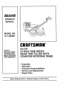
8.0 HP
21 iNCH Ti E WIDTH
REAR TINE TILLER WITH
COUNTER ROTATING TINES
• Assembly
, Operation
, Customer Responsibilities
• Service and Adjustments
, Repair Parts
.....................................................
i
i i
L
I
II=ll=
Sears, Roebuck and Co., Hoffman Estates, IL 60179 U.S.A.
.............................
,,
, ,,
,
, ,,,,,,
,, ,,, , ,, ,,,,,,,,,,,,,,,,,,,,,,,,,,,,
,,,,,,,,,
Safe Operation
SAFETY RULES Powered
Practices for Walk-Behind
°
TRAINING
•
Read the Owner's Manua{ carefully., Be thoroughly
familiar with the controls and the proper use of the
equipment. Know how to stop the unit and disengage
the controls quickly.
•
Never allow children to operate the equipment. Never
allow adults to operate the equipment without proper
instruction..
° Keep the area of operation clearof all persons,particu" tady small children, and pets.
•
•
•
PREPARATION
•
°
•
•
•
•
•
Thoroughly inspectthe area where the equipmentis to
be used and remove all foreign objects_
Disengage all clutches and shift into neutral before
starting the engine (motor)._
Do not operate the equipment without wearing adequate outer garments° Wear footwear that will improve footing on slippery surfaces.
Handle fuel with care; it is highly flammable.,
• Use an approved fuel container.
• Never add fuel to a running engine or hot engine.
• Fill fuel tank outdoors with extreme care.. Never fill
fuel tank indoors.
•
•
•
°
•
•
• Replace gasoIine cap securely and clean up spilled
fuel before restarting.
Use extension cords and receptacles as specified by
the manufacturer for all units with electric drive motors
or electric starting rnotors_
Never' attempt to make any adjustments while the
engine (motor) is running (except where specifically
recommended by manufacturer).
•
•
OPERATION
•
•
•
•
If the unit should start to vibrate abnormally, stop the
engine (motor) and check immediately for the cause.
Vibration is generally a warning of trouble_
Stop the engine (motor) when leaving the operating
position_
Take all possible precautions when leaving the machine unattended. Disengage the tines, shift into
neutral, and stop the engine.
Before cleaning, repairing, or inspecting, shut off the
engine and make certain all moving parts have stopped.
Disconnect the spark plug wire, and keep the wire
away from the plug to prevent accidental starting_
Disconnect the cord on electric motors.
Do not run the engine indoors; exhaust fumes are
dangerous.
Never operate the tiller without proper guards, plates,
or other safety protective devices in place.
Keep children and pets away.
Do not overload the machine capacity by attempting to
till too deep at too fast a rate.
Never operate the machine at high speeds on slippery
surfaces. Look behind and use care when backing_
Never allow bystanders near' the unit.
Use only attachments and accessories approved by
the manufacturer of the tiller (such as wheel weights,
counterweights, cabs, and the like).
Never operate the tiller' without good visibility or light.
Be careful when tilling in hard ground° The tines may
catch in the ground and propel the tiller' forward° if this
occurs, let go of the handlebars and do not restrain the
machine..
MAINTENANCE
•
°
Do not put hands or'feet near or under rotating parts_
Exercise extreme caution when operating on or crossing gravel drives, walks, or roads° Stay alert for hidden
hazards or traffic. Do not carry passengers.
After striking a foreign object, stop the engine (motor),
remove the wire from the spark plug, thoroughly inspect the tiller for any damage, and repair the damage
before restarting and operating the tiller_
Exercise caution to avoid slipping or'falling.
•
•
Rotary Tillers
AND STORAGE
Keep machine, attachments, and accessories in safe
working condition.
Check shear pins, engine mounting bolts, and other
bolts at frequent intervals for proper tightness to be
sure the equipment is in safe working condition.
Never store the machine with fuel in the fueltank inside
a building where ignition sources are present, such as
hot water and space heaters, clothes dryers, and the
like. Allow the engine to cool before stodng in any
enclosure.
Always refer to the operator's guide instructions for
important details if the tiller is to be stored for an
extended period.,
- IMPORTANT
CAUTIONS, IMPORTANTS, AND NOTES ARE A MEANS OF ATTRACTING ATTENTION TO IMPORTANT OR CRITICAL
iNFORMATION IN THIS MANUAL.
IMPORTANT:
POSSIBILITY
CAUTION: Look for this symbol to point
out important safety precautions, it
means--Attention! Become Alert! Your
safety is involved.
USED TO ALERT YOU THAT THERE IS A
OF DAMAGING THIS EQUIPMENT..
NOTE: Gives essential information that w{ll aid you to better
understand, incorporate, or execute a particular set of instructions.
2
PRODUCT SPECIFICATIONS
CONGRATULATIONS on your purchase of a Sears Tiller°
It has been designed, engineered and manufactured to
give you the best possible dependability and performance,.
Should you experience any probtems you cannot easily
remedy, please contact your nearest authorized Sears
Service CentedDepartment. They have competent, welltrained technicians and the proper tools to service or repair
this tillero
Please read and retain this manual. The instructions will
enable you to assemble and maintain your tiller properly
Always observe the "SAFETY RULES".
MODEL
NUMBER
HORSEPOWER:
8,0 HP
D_SPLACEMENT:
16_79cu,_in,
GASOLINECAPACITY:
4 Quarts
Unleaded Regular
OIL(API-SF/SG):
(CAPACITY:44 oz.)
SAE 30 (Above 32°F)
SAE 5W-30 (Below 32_F)
SPARK PLUG:
(GAP: 030")
Champion
RJ19LM (STD361458)
9'17.299881
SERIAL
NUMBER
MAINTENANCE
AGREEMENT
A Sears Maintenance Agreement is available on this tiller
Contact your nearest Sears store for details.
DATE OF
PURCHASE
CUSTOMER
THE MODEL AND SERIAL NUMBERS WILL BE
FOUND ON THE MODEL PLATE ATTACHED TO
THE TOP OF THE TRANSMISSION,
=
•
YOU SHOULD RECORD BOTH SERIAL NUMBER
AND DATE OF PURCHASE AND KEEP IN A SAFE
PLACE FOR FUTURE REFERENCE.
•
RESPONSIBILITIES
Read and observe the safety rules°
Follow a regularschedule in maintaining, caring for and
using your tiller.
Follow the instructions
under the "Customer
Responsibilities" and "Storage" sections of this manual
IMPORTANT:
THIS TILLER IS EQUIPPED WITH AN INTERNAL COMBUSTION
ENGINE AND SHOULD NOT BE USED
ON OR NEAR ANY UNIMPROVED FOREST-COVERED,
BRUSH-COVERED
OR GRASS COVERED LAND UNLESS THE
ENGINE'S EXHAUST SYSTEM IS EQUIPPED WiTH A SPARK ARRESTER MEETING APPLICABLE
LOCAL OR STATE
LAWS (IF ANY)° IF A SPARK ARRESTER IS USED, IT SHOULD BE MAINTAINED IN EFFECTIVE WORKING ORDER BY
THE OPERATOR
IN THE STATE OF CALIFORNIA THE ABOVE IS REQUIRED BY LAW (SECTION 4442 OF THE CALIFORNIA
PUBLIC
RESOURCES CODE),
OTHER STATES MAY HAVE SIMILAR LAWS. FEDERAL LAWS APPLY ON FEDERAL LANDS.
SEE YOUR SEARS AUTHORIZED SERVICE CENTER/DEPARTMENT
FOR SPARK ARRESTER., REFER TO THE REPAIR
PARTS SECTION OF THIS MANUAL FOR PART NUMBER°
LIMITED TWO YEAR WARRANTY ON CRAFTSMAN
TILLER
For two (2) years from date of purchase, when this Craftsman Tiller is maintained, lubricated, and tuned up
according to the operating and maintenance instructionsin the owner's manual, Sears will repair free of charge any
defect in material or workmanship,,
This Warranty does not cover:
•
Expendable items which become worn during normal use, such as tines, spark plugs, air cleaners and belts.
°
Repairs necessary because of operator abuse or negligence, including bent crankshafts and the failure to
maintain the equipment according to the instructions contained in the owner's manual
°
If this Craftsman Tiller is used for commercial or rental purposes, this Warranty applies for only thirty (30) days
from the date of purchase.
WARRANTY SERVICE IS AVAILABLE BY RETURNING THE CRAFTSMAN TILLER TO THE NEAREST SEARS
SERVICE CENTER/DEPARTMENT IN THE UNITED STATES. THIS WARRANTY APPLIES ONLY WHILE THIS
PRODUCT IS IN USE IN THE UNITED STATES,
This Warranty gives you specific legal rights, and you may atso have other rights which vary from state to state.
SEARS, ROEBUCK AND CO., D/817 WA, HOFFMAN ESTATES, ILLINOIS 60179
3
TABLE OF CONTENTS
MAINTENANCE SCHEDULE ..................................... 14
SERVICE & ADJUSTMENTS ................................ 16-19
STORAGE ................................................................... 20
TROUBLESHOOTING ................................................. 21
REPAIR PARTS-TILLER ....................................... 22-28
REPAIR PARTS-ENGINE ...................................... 29-32
SERVICFJPARTS ORDERING ............... BACK COVER
SAFETY RULES ............................................................ 2
CUSTOMER RESPONSIBILITIES ...................... 3,14-16
PRODUCT SPECIFICATIONS ....................................... 3
WARRANTY .................................................................. 3
ACCESSORIES ............................................................. 5
ASSEMBLY ...............................................................
6-8
OPERATION ............................................................
9-13
INDEX
A
R
Engine (cont'd)
Lubrication ................................ 15
Repair Parts:
Oil Level ..............................................
11
Tiller ...............................
22-28
Adjustments:
Oil Type ............................. 11,15
Engine ................................ 29-32
Carburetor ............................................
19
Spark Plug .............................. 16
Rules for Safe Operation .......................
2
Depth Stake .............................. 10
Starting .......................................................
12
Handle Height .......................... 16
Stopping .................................. 10
Side Shields .............................. 11
S
Storage ..................................... 20
Throttle ...........................................
19
Winter Operation .........................15 Service & Adjustments:
Tines ...............................................
18
Carburetor ................................ 19
V-Belt (Ground Drive) ......................
17
F
Handle Height .......................
16
Wheels ....................................... 13
Side Shields ................................11
Fuel:
Air Cleaner .........................................15
Throttle .............................
19
Filling Tank .........................................
11
Tines ..............................
t8
Storage ................................... 20
B
V-Belt (Ground Drive) .................
t7
Type ..............................................
11
Wheels
...............................
13,
16
Belt:
Finish:
Belt Guard .......................................
17
Maintenance ................................
16 Service:
Repair Parts ..............................
22-32
Repair Parts ................................23
Service Record ......................
14
V-Belt (Ground Drive) ...............17
H
Spark Plug:
Handle:
C
Gap ........................................... 3
Height Adjustment ......................16
Maintenance ........................... 16
Cooling System .................................15
Repair Parts ............................................
22
Storage:
Controls:
Fuel System .........................
20
Choke ..............................................
9
L
Tiller ......................................... 20
Throttle ........................................ 9 Lubrication:
Drive pines) ..................................
9
Lubrication Chart .................... 14
T
Cultivating ....................................... 13
Engine ..................................... 15
Tilling ........................................ 10,12
Customer Responsibilities:
Tines:
Air' Cleaner ..................................15
M
Cooling System ......................... 15 Muffler:
Arrangement/Replacement ..... t 8
Finish .............................................
16
Operation .....................................10
Maintenance
..................................
16
Maintenance Schedule .............14
Repair Parts ............................ 27
Spark Arrester ...............................3 Transmission:
Muffler ........................................ t6
Oil Change ........................................
15
Maintenance ........................... t6
O
Spark Plug ....................................
16
Repair Parts ............................ 25
Trees ........................................ 18 Oif:
Troubleshooting
.......................................
21
Transmission .............................i6
Level .............................................
11
Transporting
..................................
11
V-Belt (Ground Drive) ............. 17
Type ..............................................
11,15
Accessories ...................................... 5
D
Depth Stake:
Adjustment ............................... 10
Repair Parts .................................
26
E
Engine:
Air Cleaner, ......................................
15
Cooling System ...............................
15
Fuel Type ............................................
11
Operation:
W
Cultivating ........................................
13
Fill
Fuet Tank .............................
11 Warranty ...............................
3
Starting Engine ...........................12 Wheels:
Stopping Tines & Engine ........ 10
Adjustment
13
Tilling ...........................................................
10
Removal .................................. I6
Tilling Hints .................. _.......... 12
Repair Parts ........................
24
Tine Operation ...............................
10
Transporting Tiller', .................... 11
Winter Operation ................................
15
.......................................
4
.........
ii
iiiiii
ACCESSOR
,, i i,i1,111,1,111M i,i1,1 i
l llll
IT
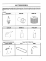
These accessories were available when the tiller was purchased. They are also available at most Sears Retail outlets
and Service Centers. Most Sears Stores can order repair parts for you when you provide the model number of your
tiller°
ENGINE
..............
_,,,,_,,,, ,,,,_,,,,,,,_
..............
MUFFLER
SPARK PLUG
AIR FILTER
i
/1/1/111/1111/11_11
...........
GAS CAN
........................
ENGINE OIL
,,,,,,,,,
,,,,,i,i,ij, i
I ,IlUlI,II
i
TILLER
TILLER
PERFORMANCE
BELT
...........
FURROW oPENER
.............
,,,,,
,,,,,,,
5
MAINTENANCE
TINES
iiiiiiiiiillllllllll
illlll
ii
ASSEMBLY
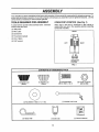
Your new tiller has been assembled at thefactory with exception of those parts left unassembled for shipping purposes. To
ensure safe and proper' operation of your tiller all parts and hardware you assemble must be tightened securely. Use the
correct tools as necessary to insure proper tightness°
TOOLS
REQUIRED
FOR ASSEMBLY
OPERATOR'S
A socket wrench set will make assembly easier. Standard
wrench sizes are listed.
POSITION
(See Fig. 1)
When right or left hand is mentioned in this manual, it
means when you are in the operating position (standing
behind tiIler handles)_
(1) Utility knife
FRONT
(1) Wire cutter
(t) Screwdriver
(t) Tire pressure gauge
(1) Pair of pliers
(1) 9/16" wrench
LEFT
RIGHT
OPERATOR'S
POSITION
FIG. 1
CONTENTS OF HARDWARE
, , ,,
,
PACK
ii ,, i ,,lll,,,,ml
Ill
Illll
Illll
I
Illllllll
Q
(1) Handle Lock
(Black)
(2) Carriage Bolts
3/8-16 UNC x I Gr. 5
(1) Handle Lock
(Silver)
(2) Center Locknuts
3/8-16 UNC
©
(1) Handle Lock Lever
(1) Flat Washer 13/32 x I x 11 Ga.,
(1) Hairpin Clip
(1)Cable Clip
6
(1) Owner's Manual
ASSEMBLY
UNPACKING
CARTON
......
I &
i,
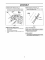
Grasp handle assembly. Hold in"up"position, Be sure
handle lock remains in gearcase notch. Slide handle
assembly into position,,
(See Fig. 2)
i Hl,,H'l
L
II
staples when handling or disposing of
CAUTION:
Be careful of exposed
carton,!,ng material.
I I%
I
HANDLE ASSEMBLY
"UP" POSITION
IMPORTANT:
WHEN UNPACKING AND ASSEMBLING
TILLER, BE CAREFUL NOT TO STRETCH OR KINK
CABLES,,
=
.
While holding handle assembly, cutcabletiessecuring
handle assembly to top frame and depth stake. Let
handle assembly rest on tiller,,
. Remove.top frame of carton.
°
Slowly ease handle assembly up and place on top of
carton,
=
Cut down right hand front and right hand rear corners
of carton° Lay side carton wall down,.
Cut down left hand rear comer of carton. Lay rear
carton wall down, which wit! remove the protective
cardboard flap from leveling shield,,
°
o
LOCK LEVER TO
TIGHTEN HANDLE 1
HOLD
FIG. 4
Remove packing material from handle assembly.,
o
Rotate handle assembly down. Insert rear carriage
bolt first, with bolt head on LoHoside of tiller (See Fig. 5)°
o
Insert front carriage bolt with care, since space for
installation is limited,
o
Lowerthe handle assembly,, Tighten Iocknuts on bolts
so handie moves with some resistance,,
Place flat washer on threaded end of handle lock lever.
SHIFT ROD
o
HANDLE
ASSEMBLY
FIG. 2
INSTALL HANDLE
=
(See Figs. 3, 4, and 5)
o
Insert handle lock lever through handle base and
gearcaseo Screw in handle lock lever just enough to
hold lever in place°
o
Insert the thinner silver handle lock (with teeth inward)
in the slot of the handle base (just inside of washer),,
o
With handle assembly in lowest position, securely
tighten handle lock lever by rotating clockwise° Leaving handle assembly in lowest position wilt make it
easier to remove tiller from carton.
Insert the thicker black handle lock (with teeth facing to
the right) in gearcase notch°
HANDLE
LOCK
SLOT
VIEWED FROM R,H. SIDE OF TILLER
CARRIAGE
_'_',,,\\.
BOLT
HANDLE ASSEMBLY
.h\ "-._%_%
_,_'\j_y
/
/
FLAT
WASHER
_X\
/
HANDLE
LOCK
LEVER
BLACK
HANDLE
REAR
CARRIAGE
BOLT
LOCKNUTS
HANDLE
BASE
FIG. 3
FIG. 5
7
A
CONNECT
SHIFT ROD (See Fig. 6)
=
insert end of shift rod into hole of shift lever indicator_
•
insert hairpin clip through hole of shift rod to secure.
SHIFT
HAIRPIN
CLIP
INSERT CABLE CLIP (See Fig. 7)
•
SHIFT
LEVER
INDICATOR
Insert plasticcable clip into hole on the back of handle
column. Push cables into clip,,
HANDLE
COLUMN
CABLES
CABLE CLiP
FIG. 6
REMOVE TILLER
FIG. 7
FROM CRATE
•
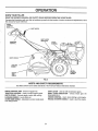
Make sure shift lever indicator is in "N" (neutral) position (See Fig. 6)
•
Tilt tiller forward by lifting handle_
•
Rotate tiller handle to the right and pull tiller out of
carton.
CHECK TIRE PRESSURE
The tires on your tiller were overinflated at the factory for
shipping purposes. Correct and equal tire pressure is
important for' best tilling performance.
•
Reduce tire pressure to 20 PSi°
HANDLE HEIGHT
•
8
Handle height may be adjusted to better suit operator_
(See 'q'O ADJUST HANDLE HEIGHT" in the Service
and Adjustments section of this manual)=
lUUUUUUllUUl
_1iJ
........
OPERATI
,, ,iiii
i_i_,ll_,,_,,u,
LL'I I , ,
,
iii
i ..........................
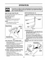
KNOW YOUR TILLER
READ THIS OWNER'S MANUAL AND SAFETY RULES BEFORE OPERATING YOUR TILLER.
Compare the illustrationswith your tiller to familiarize yourself with the location of various controls and adjustments° Save
this manual for future reference.
DRIVE
CONTROL
SHIFT LEVER
SHIFT LEVER
INDICATOR
THROTTLE
CONTROL
CHOKE
CONTROL
DEPTH STAKE
LEVELING
SHIELD
RECOIL
STARTER
HANDLE
OUTER
SIDE
SHIELD
FIG. 8
MEETS ANSi SAFETY REQUIREMENTS
Our titlers conform to the safety standards of the American Nationat Standards Institute,,
DRIVE CONTROL BAR - Used to engage tines.
THRO'B'LE CONTROL - Used to control engine speed.,
DEPTH STAKE - Controls depth at which tiller wiil dig,,
LEVELING SHIELD - Levels tilled soil.
OUTER SIDE SHIELD - Adjustable to protect small plants
from being buried.
SHIFT LEVER - Used to shift transmission gears_
SHIFT LEVER INDICATOR - Shows which gear the
transmission is in.
CHOKE CONTROL - Used when starting a cold engine.
RECOIL STARTER HANDLE - Used to start the engine,,
9
OPERATION
The operation of any tiller can result in foreign objects thrown into the eyes, which can
result in severe eye damage. Always wear safety glasses or eye shields before starting
your tiller and while tilling. We recommend a wide vision safety mask for over the spectacles or standard safety glasses.
i lltIHHlul
I lll
HOW TO USE YOUR
i
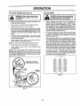
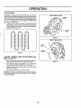
DEPTH STAKE (See Fig. 10)
TILLER
Tile depth stake can be raised or loweredto allow you more
versatile tillingand cultivating,or to more easily transport
_ourtiller,
Know how to operate all controls before adding fuel and
oil or attempting to start engine.
STOPPING
I
(See Fig. 9)
TINES AND DRIVE
•
Release drive control bar to stop movemenL
•
Move shift lever to "N" (neutral) position°
POSITION
SHALLOWEST
TILLING
ENGINE
°
Move throttle contro! to "STOP" position°
°
Never use choke to stop engine_
DRIVE CONTROL BAR
"ENGAGED" POSITION
.
_/CONTROL
"\-.
DEEPESTJ
TILLING
/THROTTLE
DEPTH_
STAKE
__
SHIFT
FIG. 10
TILLING (See Fig. 11)
DRIVE CONTROL BAR
"DISENGAGED" POSITION
•
•
°
Place shift lever indicator in 'q" (till) position_
•
Hold the drive contro_bar against the handle to start
tilling movement, Tines and wheels wilt both turn.
Move throttle controlto "FAST" positionfor deep tilling.
To cultivate, throttle control can be set at any desired
speed, depending on how fast or slow you wish to
cultivate.
IMPORTANT: ALWAYS RELEASE DRIVE CONTROL BAR
BEFORE MOVING SHIFT LEVER INTO ANOTHER
POSITION
- WITH WHEEL DRIVE
Always release drive control bar before moving shift
lever into another position°
DEPTH STAKE PiN
"RELEASED" POSITION
\
Tine movement is achieved by movingshift lever to 'T'
(till)position and engaging drive controlbar°
FORWARD
•
Release depth stake pin. Pul! the depth stake up for
increased tillingdepth. Place depthstake pin in holeof
depth stake to lock in position°
•
FIG. 9
TINE OPERATION
•
- WHEELS
ONLY/TINES
STO PPED
Release drive control bar and move shift lever indicator
to "F' (forward) position. Engage drive control bar and
tiller will move forward_
REVERSE
- WHEELS ONLY/TINES
STOPPED
•
•
DO NOT STAND DIRECTLY BEHIND TILLER.
Release the drive control bar.
•
Move throttle control to "SLOW" position,.
•
o
Move shift lever indicator to "R" (reverse) position
Hold drive control bar against the handle to start tiller
movement,
"LOCKED"
POSITION
NUT"A"
OUTER
SIDE SHIELD
/
NUT"B"
FIG. 11
10
OPERATION
TURNING
CHECK ENGINE OIL LEVEL (See Fig. 12)
o
Release the drive control bar,,
o
The engine in your tiller has been shipped, from the
factory, already filled with SAE 30 summer weight oil,
°
Move throttle control to "SLOW" position.,
.
o
Place shift lever indicator in "F" (forward) position.,
Tines will not turn,,
With engine level, clean area around oil filler plug and
remove plug_
•
Lift handle to raise tines out of ground.
•
o
Swing the handle in the opposite direction you wish to
turn, being careful to keep feet and legs away from
tines°
Engine oil should be to point of overflowing. For
approximate capacity see "PRODUCT SPECIFICATIONS" on page 3 of this manual., All oil must meet
A.P,I. Service Classification SGo
°
°
When you have completed your turn-around, release
the drive control barand lower handle_ Place shift lever
-_in-"T"(till) posffion andmove_throttle control_todesired - *speed° To begin tilling, hold drive control bar against
the handle.
For cold weather operation you should change oil for
easier starting (See oil viscosity chart in the Customer
Responsibilities section of this manual).
OUTER SIDE SHIELDS
° - To_change_engineoilTseetheCustomer
ties section in this manual.
(See Fig, 11)
The front edges of the outer side shields are slotted so that
the shields can be raised for deep tilling and lowered for
shallow tilling to protect small plants from being buried.
Loosen nut "A" in slot and nut "B". Move shield to desired
position (both sides). Retighten nuts°
OIL
TO TRANSPORT
OIL
FILLER
PLUG
CAUTION: Before lifting or transporting, allow tiller engine and muffler to
cool. Disconnectsparkplugwire. Drain
gasoline from fuel tank.
..........................................
ill
PLUG
FIG. 12
ADD GASOLINE
.............
AROUND THE YARD
o
Release the depth stake pin,, Move the depth stake
down to the top hole for transporting the tiller,, Place
depth stake pin in hofe ofdepth stake to lock in position,.
This prevents tines from scuffing the ground.
=
Place shift lever indicator in "F" (forward) position for
transporting°
Hold the drive control bar against the handle to start
tiller movement. Tines will not turn.,
°
.
Responsibili-
°
Fill fuel tank..
Use fresh, clean, regular unleaded
gasoline. (Use of leaded gasoline will increase carbon
and lead oxide deposits and reduce valve life..
IMPORTANT;
WHEN OPERATING IN TEMPERATURES
BELOW 32°F (O°C), USE FRESH, CLEAN, WINTER GRADE
GASOLINE TO HELP INSURE GOOD COLD WEATHER
STARTING
WARNING: Experience indicates that alcohol blended
fuels (called gasohol or using ethanol or methanol) can
attract moisture which leads to separation and formation of
acids during storage° Acidic gas can damage the fuel
system of an engine while in storage,i To avoid engine
problems, the fuel system should be emptied before storage of 30 days or longer. Drain the gas tank, start the
engine and let it run untit the fuel lines and carburetor are
empty° Use fresh fuel next season, See Storage section
of this manual for additional information, Never use engine
orcarbu retor cTeanerproducts in the fuel tank or permanent
damage may occur.
Move throttle control to desired speed_
AROUND TOWN
•
°
Disconnect spark plug wire.
Drain fuel tank.
=
Transport in upright position to prevent oit leakage_
BEFORE STARTING ENGINE
IMPORTANT:
BE VERY CAREFUL NOT TO ALLOW DIRT
TO ENTER THE ENGINE WHEN CHECKING OR ADDING
OIL OR FUEL. USE CLEAN OIL AND FUEL AND STORE
IN APPROVED, CLEAN, COVERED CONTAINERS.
USE
CLEAN FILL FUNNELS.
A
CAUTION: Fill to within 112inch of top
of fuel tank to prevent spills and to
allow for fuel expansion. If gasoline is
accidentally spilled, move machine
away from area of spill. Avoid creating
any source of ignition until gasoline
vapors have disappeared.
Do not overfill. Wipe off any spilled oil
or fuel. Do not store, spill or use gasoline near an open flame.
11
OPERATION
TO START ENGINE
TILLING
(See Fig. 13)
HINTS
i LIIIILIIIHIIlUl
'
I I IIllL II
CAUTION: Until you are accustomed to
handling your tiller, start actual field
use with throttle in slow position.
..................................
•
,
,,
,,,,, ,,,,,, ,,,,,,,,,,,, ,,,
•
Make sure spark plug wire is properly connected, and
fuel shut-off valve is open.
Move shift lever' indicator to "N" (neutral) position°
°
Place throttle control in "FAST" position.
•
With engine fully choked, grasp recoil starter handle
with one hand and grasp tiller handle with other hand_
Pu'iJ_r0peout slowly un_[_n_5_-S-st-_.rt
df-50r_--....
pression cycle (rope will pull slightly harder at this
point)°
Pull recoil starter handle quickly_ Do not let starter'
handle snap back against starter'. Repeat if necessary
in half choked position.
When engine starts, slowly move choke control to
"RUN" position as engine warms up.
•
•
•
Tilling is digging into, turning over, and breaking up
packed soil before planting. Loose, unpacked soil
helps root growth_ Best tilling depth is 4" to 6". A tiller'
wil! also clear the soil of unwanted vegetation. The
decomposition of this vegetable matter enriches the
soil Depending on the climate (rainfall and wind), it
may be advisable to till the soil at the end of the growing
.....-seasor_toofurtheroeondition-thesoil.. •
•
For'easier handling of your tiller, leave about 8 inches
of untilled soil between the first and second tilling
passes_ The third pass will be between the fhst and
second (See Fig. t4).
Soil conditions are importantfor'proper tilling. Tines will
not readily penetrate dry, hard soil which may contribute to excessive bounce and difficult handling of your
tiller. Hard soil should be moistened before tilling;
however, extremely wet soil will "ball-up" or clump
during tilling. Wait until the soil is less wet in order to
achieve the best results. When tilling in the fal!, remove
vines and long grass to prevent them from wrapping
around the tine shaft and slowing your tilling operation.
•
NOTE: A warm engine requires less choking to start..
•
Move throttle control to desired running position.
•
Allow engine to warm up for a few minutes before
engaging tines.
NOTE: If at a high altitude (above 3000 feet) or' in cold
temperatures (below 32°F), the carburetor fuel mixture
may need to be adjusted for'best engine performance. See
"TO ADJUST CARBURETOR" in the Service and Adjustments section of this manual.
-
Do not lean on handle. This takes weight off the wheels
and reduces traction. To get through a really tough
section of sod or hard ground, apply upward pressure
on handle or lower the depth stake.
//
//
//
//
SHUT-OFF VALVE
(UNDERNEATH GAS TANK)
//
//
i.,,-
g
PLUG
CHOKE
,CONTROL
//
FIG. 14
RECOIL STARTER HANDLE
FIG. 13
12
OPERATi
CULTIVATING
Cultivating is destroying the weeds between rows to prevent them from robbing nourishment and moisture from the
plants. At the same time, breaking up the upper layer of soit
crust will help retain moisture in the soil. Best digging depth
is I" to 3". Lower the outer side shields to protect small
plants from being buried°
-
OUTER VIEW OF TIRE
. CLEVIS
Cultivate up and down the rows at a speed which will
allow tines to uproot weeds and leave the ground in
rough condition, promo!ing no further growth of weeds
and grass (See Fig,, 15)4
PIN
A
A
\..j-"
FIG. 16
t-..
INNER VIEW OF TIRE
;i.\
-_j..
CLEVIS
\
FIG. 15
ADJUST WHEELS
Figs. 16 and 17)
FOR CULTIVATING
(See
o
Place blocks under right hand side of tUler and remove
hairpin clip and clevis pin from right hand wheel..
-
Move wheel outward approximately 1 inch until hole in
inner wheel hub lines up with inner hole in axle,.
•
Replace clevis pin and hairpin clip on inside of wheel
and remove blocks.
FIG. 17
o Repeat preceding steps on left hand side°
NOTE: in extremely rough conditions and while cultivating,
the wheels should be moved outward on the axle for
increased stability°
13
IBI
CUSTOMER
MAINTENANCE
SCHEDULE
.........................
..
FILL IN DATES
AS YOU COMPLETE
REGULAR SERVICE
SERVICE
,/
Check Engine Oil Level
DATES
,/
= ....................
Change Engine Oil
Oil Pivot Points
v"
"
v'
inspect Spark Arrester / Muffler
v'
Inspect Air' Screen
Clean or' Replace Air Cleaner Cartridge
v'
Clean Engine Cylinder Fins
V'i
Replace Spark Plug
1 - Change more often when operating
2 - Service more often when operating
under a heavy toad or in high ambient
in dirty or dusty conditions,
temperatures
LUBRICATION
GENERAL RECOMMENDATIONS
CHART
The warranty on this tiller does not cover items that have
been subjected to operator abuse or negligence. To
receive full value from the warranty, the operator must
maintain tiller' as instructed in this manual.
* THROTTLE
CONTROL
Some adjustments will need to be made periodically to
properly maintain your tiller..
** ENGINE
All adjustments in the Service and Adjustments section of
this manual should be checked at least once each
season..
•
* DEPTH STAKE
PIN
Once a year' you should replace the spark plug, clean
or replace air flter, and check tines and belts for wear.
A new spark plug and clean air filter assure proper airfuel mixture and help your engine run better and last
longer..
BEFORE
EACH
LEVELING
HINGES
USE
•
Check engine oil level.
°
°
Checktine operation.
Check for' loose fasteners_
* IDLER
BRACKET
WHEEL
HUB
LUBRICATION
* SAE 30 OR 10W-30 MOTOR OIL
** REFER TO CUSTOMER RESPONSIBILITIES
Keep unit well lubricated (See "LUBRICATION CHART") ..
14
l=
ENGINE
zf
SECTION
CUSTOMER
RESPONSIBILF[IES
......................................
A
] ii1,1111
iii1,111111
i1,1,,,111,i i1,1
]1,, ]11,,,,, i
I
Disconnect spark plug wire before performing any maintenance (except carburetor adjustment) to prevent
accidental starting of engine.
Prevent fires! Keep the engine free of grass, leaves, spilled oil, or fuel. Remove fuel from tank before tipping
unit for maintenance. Clean muffler area of all grass, dirt, and debris.
Do not touch hot muffler or cylinder fins as contact may cause burns°
i i ,,,,i,i i i,iH i,,
'H'I""H"' "ll' Im'
ENGINE
AIR CLEANER (See Fig. 20)
LUBRICATION
Service air cleaner cartridge every 25 hours of operation,
more often if engine is used in very dusty conditions.
Use only high quality detergent oit rated with API service
classification SF orSGo Select the oil s SAE viscosity grade
according to your expected temperature_
=
•
.......
SAE VlSG_SiTYGRADES
°---Remove-wing-nut-and-cup_.
....................
4
,_F
"20 _
=C *30 _
TEMPERA_RE
0"
30 _
32"
-10 ° .......
O°
40"
RANGE ANTICIPATED
80_
60 °
t0 =
20 °
Remove the knob securing air cleaner cover.
Remove air cleaner cover°
_00_
30"
•
Carefully remove air cleaner cartridge° Be careful. Do
not allow dirt or debris to fall into carburetor°
•
Clean by tapping gently on a flat surface°
=
tf very dirty, replace or washin a nonsudsing detergent
and warm water solution,, Rinse thoroughly with water
flowing from mesh side until water is clear. Allow
cartridge to stand and air dry thoroughly before using.
Clean and replace cup, wing nut and cover. Tighten
wing nut and knob securely.
40"
BEFORE NEXT OIL CHANGE
FIG. 18
NOTE: Although multi-viscosity oils(5W-30,10W-30, etc.)
improve starting in cold weather, these multi-viscosity oils
wilt result in increased oil consumptionwhen used above
32°F (0°C). Check your engine oit level more frequentIy to
avoid possible engine damage from running low on oil
Change the oil after the first two hours of operation and
every 25 hours thereafter or at least once a year if the tiller
is not used for 25 hours in one year°
Check the crankcase oil level before starting the engine
and after each five (5) hours of continuous use. Add SAE
30 motor oil or equivalenL Tighten oil filler plug securely
each time you check the oil level
•
'M''1
I...............................
CAUTION: Petroleum solvents, such
as kerosene, are notto be used to clean
cartridge. They may cause deterioration of the cartridge. Do not oil cartridge. Do not use pressurized air to
clean or dry cartridge.
!
|
F
KNOB
TO CHANGE ENGINE OIL (See Figs. 18 and 19)
Determine temperature range expected before oil change°
All oit must meet API service classification SF or SG.,
.
.
.
•
°
.
°
•
\
_UP
Be sure tiller is on level surface,,
Oil will drain more freely when warm.,
Use a funnel to prevent oit spill on tiller, and catch oil in
a suitable container,,
Remove drain plug,,
Tip tiller forward to drain oil
After oil has drained completely, replace oil drain plug
and tighten securely,,
Remove oil filler ptug. Be careful not to allow dirt to
enter the engine.
Refill engine with oil. See "CHECK ENGINE OIL
LEVEL" in the Operation section of this manual,,
AIR CLEANER
CARTRIDGE
FIG, 20
COOLING
SYSTEM (See Fig. 21)
Your engine is air cooled., For proper engine performance
and long life keep your engine clean.
°
Clean air screen frequently using a stiff-bristled brush°
°
Remove blower housing and clean as necessary,
Keep cylinder fins free of dirt and chaff.
CYUNDER
FINS
OIL
DRAIN
PLU G ,_.\.,.
IL LEVEL
",OIL
FIG. 19
AIR SCREEN
FILLER
PLUG
15
FIG. 21
L
I
I
III
IIILIIIIL
I
............................................................
CUSTOMER
SIBILITIES
MUFFLER
TRANSMISSION
Do not operate tiller without muffler'. Do not tamper with
exhaust system., Damaged mufflers or spark arresters
could create a fire hazard. Inspect periodically and replace
if necessary. If your engine is equipped with a spark
arrester screen assembly, remove every 50 hours for
cleaning and inspection. Replace if damaged.
Your transmission issealed and will only require lubrication
if serviced.
•
Clean engine, wheels, finish, etco of all foreign matter.
SPARK
•
Keep finished surfaces and wheels free of all gasoline,
oil, etc_
•
Protect painted surfaces with automotive type wax,
CLEANING
PLUG
Replace spark plugs at the beginning of each tillingseason
or after every 50 hours of use, whichevercomes first. Spark
plug type and gap setting is shown in "PRODUCT SPEC!•-- FIGA-T-tONS"en page 3 of'-thismanual_-- .....
We do not recommend using a garden hose to clean your
unit unless the muffler, air filter and carburetor are covered
to keep wat_}i_6_i5-e-_gine
can result=_a:shortened
engine life.
..............................................
,i,,i,llll,,lllllllllll
,llll
, lllll ii i [ i llll ii i
ICE AND ADJUSTMENTS
CAUTION: Disconnect spark plug wire from spark plug and place wire where it cannot come into
contact with plug,
TILLER
TIRE CARE
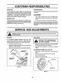
TO ADJUST HANDLE
HEIGHT (See Fig. 22)
Select handle height best suited for your tillingconditions,.
Handle height will be different when tiller digs into soil
•
First loosen handle lock lever:
•
Handle can be positioned at different settings between
"HIGH" and "LOW" positions.
•
Retighten handle lock lever securely after' adjusting.
less beads are seated, overinflation
CAUTION:
When
mounting tires, uncan
cause an
explosion.
I _
III
I
IIUII
IIIII
I
IIIII
II
II
°
Maintain 20 pounds of tire pressure_ If tire pressures
are not equal, tiller will pull to one side.
-
Keep tires free of gasoline or oil which can damage
rubber_
TO REMOVE WHEEL (See Fig. 23)
*
=
Place blocks under transmission to keep tiller from
tipping,.
Remove hairpin dip and clevis pin from wheel.
Remove wheel and tire_
.
Repair tire and reassemble.
FIG. 22
,_o
FIG. 23
16
""
..
H_RP_tN CLIP
SERVmCE AND ADJUSTMENTS
IIU,lUUUUHlUUL
ul, 'l 'm'
TO REMOVE
Remove hairpinclip and clevis pinfrom leftwheel Pull
wheel out from tiller about 1 inch.
°
Remove cap nut and washer, and 13/16 bolt and
washer from side of belt guard.
°
Remove hex nut and washer from bottom of belt guard
(located behind wheel).
°
Pull belt guard out and away from tiller°
°
Replace bett guard by reversing above procedure,,
BELT GUARD
CAI_.NU_TJ_ND
WA_ HER
I
U"UUlI"'Ul
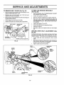
TO REPLACE
(See Fig. 25)
BELT GUARD (See Fig. 24)
o
I
GROUND
ll'
DRIVE BELT
=
Remove belt guard. (See"TO REMOVE BELT GUARD"
in this section of this manual),
•
Loosen belt guides 'W' and "B"o
°
Remove old belt by slipping from engine pulley first,
°
Place new belt in groove of transmission pulley and
into engine pulley,, BELT MUST BE IN GROOVE ON
TOP OF IDLER PLILLEYo NOTE POSITION OF BELT
TO GUIDES.
°
Tighten belt guides "A" and "B".
.... _
CS_SkS_lta-a-d_t_e_t_s'des_ribed
below.
o
Replace belt guard°
.
Reposition wheel and replace clevis pin and hairpin
clip.
GROUND
Fig. 25)
DRIVE BELT ADJUSTMENT
(See
For proper belt tension, the extension spring should have
about 5/8 inch stretch when drive control bar is in "ENGAGED" position. This tension can be attained as follows:
•
Loosen cable clip screw securing the drive control
cable.
°
Slide cable forward for less tension and rearward for
more tension until about 5/8 inch stretch is obtained
while the drive control bar is engaged..
Tighten cable clip screw securely,
HAIRPIN CLIP AND CLEVIS PIN
FIG, 24
-
BELT
GUIDE "A"
ENGINE
PULLEY
CABLE CLIP
SCREW
BELT
,GUIDE"B"
CONTROL
CABLE
LESS
TENSION
IDLER
PULLEY
SPRING
TRANSMISSION
PULLEY
FIG. 25
17
SERVICE AND ADJUSTMENTS
TINE REPLACEMENT
(See Figs. 26, 27 and
•
To maintain the superb tilling performance of this
machine the tines should be checked for sharpness,
wear, and bending,particularlythe tines which are next
to the transmission, If the gap between the tines
exceeds 3-1/2 inches they should be replaced or
straightened as necessary.
•
New tines should be assembled as shown in Fig. 28°
Sharpened tine edges willrotate rearward from above.
28)
i _
gloves or other protection when hanCAUTION:
Wear
dling tines. Tines are sharp.
A badly worn tine causes your tiller to work harder and dig
more shallow° Most important, worn tines cannot chop and
shred organic matter as effectively nor bury it as deeply as
good tines. A tine this worn needs to be replaced_
NEW TINE
TINE
TRANSMISSION
WORN TINE
TINE
FIG. 27
FIG. 26
SHARP EDGES
_!
COUNTERITINE
ROTATION
SHARP EDGE
HAIRPIN CLIP
CLEVIS PIN
SHARP EDGE
SHARP EDGE
SHARP
FIG. 28
18
EDGES
ENGINE
TO
ADJUST
PRELIMINARY SETTING
THROTTLE
CONTROL
CABLE
(See Fig. 29)
•
Air cleaner assembly must be assembled to the carburetor when making carburetor adjustments.
°
The throttle control has been preset at the factory and
adjustment should not be necessary. Check adjustment as
described below before loosening cable. If adjustment is
necessary, proceed as follows:
Be sure the throttle control cable is adjusted properly
(see above)..
•
With engine off turn idle mixture valve in (clockwise)
closing it finger tight and then turn out (counterclockwise) 1 full turn,
o
With engine not running, move remote throttle control
lever to "FAST" position..
•
Turn needle valve in (clockwise) closing itfinger tight
and then out (counterclockwise) 1-I/2 turns,
•
Checkthat holes "A" in governor control lever and hole
in governor plate line-upo If holes "A" are not aligned,
-loosen ctamp screw and move-threttleeableuntil.-heles
are aligned. Tighten clamp screw securely.
FINAL SETTING
.-. .... Start-engine-andallow-to-warmfor.fiveminuteso
Make
final adjustments with engine running and drive control
bar in "NEUTRAL" position_
GOVERNOR
CONTROL
LEVER
THROTTLE
CABLE
•
Move remote throttle control lever to "FAST" position_
Turn needle valve in (clockwise) until engine begins to
die and then turn out (counterclockwise) until engine
runs rough, Turn valve to a point midway between
those two positions. Release throttle control levero
-
Move remote throttle control lever to "SLOW" position,,
Rotate and hold throttle against idle speed screw. Turn
idle speed screw to attain 1850 RPM.
°
While still holding throttle against idle speed screw,
turn idle mixture valve in (clockwise) until engine
begins to die and then turn out (counterclockwise) until
engine runs rough. Turn valve to a point midway
between those two positions_ Release throttle,.
ACCELERATION TEST
•
',,.GOVERNOR
CONTROL PLATE
High speed stop is factory adjusted.
Do not adjust damage may result°
IMPORTANT:
NEVER TAMPER
WITH THE ENGINE
GOVERNOR,
WHICH IS FACTORY SET FOR PROPER
ENGINE SPEED° OVERSPEEDING
THE ENGINE ABOVE
THE FACTORY
HIGH SPEED
SETTING
CAN BE
DANGEROUS° IF YOU THINK THE ENGINE-GOVERNED
HIGH SPEED NEEDS ADJUSTING,
CONTACT
YOUR
NEAREST
AUTHORIZED
SERVICE
CENTER/
DEPARTMENT, WHICH HAS PROPER EQUIPMENT AND
EXPERIENCE
TO
MAKE
ANY
NECESSARY
ADJUSTMENTS..
FIG. 29
TO ADJUST CARBURETOR
Move remote throttle control lever from "SLOW" to
"FAST" position,
if engine hesitates or dies, turn idle
mixture valve out (counterclockwise)
1/8 turn. Repeat
test and continue to adjust, if necessary, until engine
accelerates smoothly..
(See Fig. 30)
The carburetor has been preset at the factory and adjustment should not be necessary., However, minor adjustment may be required to compensate fordifferences infuel,
temperature, altitude or Ioado If the carburetor does need
adjustment, proceed as follows:
In general, turning valves in (clockwise) decreases the
supply of fuel to the engine giving a leaner fueVair mixture°
Turning the valve out (counterclockwise) increases the
supply of fuel to the engine giving a richer fueVair mixture_
IMPORTANT: DAMAGE TO THE VALVE AND THE SEAT
IN CARBURETOR MAY RESULT IF SCREW IS TURNED
IN TOO TIGHT.
THROTTLE
IDLE MIXTURE
VALVE
IDLE
SPEED
SCREW
THROTTLE
STOP
NEEDLE VALVE(HIGH
FIG, 30
19
SPEED)
.......... •
....................................
....
-
IH
III
IlltLllll II
STORAGE
.................................
tu
lluHllL
Never store the tiller with
where fumes may reach an open flame
gasoline in the tank inside a building
or spark. Allow the engine to cool
before storing in any enclosure.
::
:
lllltlll]
!
tll
t
Remove spark plug.
°
Pour I ounce (29 ml) of oil through spark plug hole into
cylinder,
Pull starter handle slowly several times to distribute oil,
•
Clean entire tiller (See "CLEANING" in the Custorne[ ............
- .... R e_p_!a_ with ne.,.w...s_a!'kpj.ug...........
R_-onsibilities
secti0_-_f t_is"i'n--_n_l)\
_ .................
•
Be sure that all nuts, bolts and screws are securely
fastened. Inspect moving parts for damage, breakage
and wear. Replace if necessary.
°
°
Touch up all rusted or' chipped paint surfaces; sand
lightly before painting.
°
•
°
FUEL SYSTEM
IMPORTANT:
IT IS IMPORTANT TO PREVENT GUM
DEPOSITS FROM FORMING IN ESSENTIAL FUEL
SYSTEM PARTS SUCH AS THE CARBURETOR, FUEL
FILTER, FUEL HOSE, OR TANK DURING STORAGE.
ALSO, EXPERIENCE INDICATES THAT ALCOHOL
BLENDED FUELS (CALLED GASOHOL OR USING
ETHANOL OR METHANOL) CAN ATTRACT MOISTURE
WHICH LEADS TO SEPARATION AND FORMATION OF
ACIDS DURING STORAGE. ACIDIC GAS CAN DAMAGE
THE FUEL SYSTEM OF AN ENGIN E WHILE IN STORAGE.
•
Drain the fueltank.
•
Start the engine and let it run until the fuel lines and
carburetor are empty.
•
Never' use engine or carburetor cleaner products in the
fuel tank or' permanent damage may occur'.
Use fresh fuel next season.
Do not store gasoline from one season to another.
Replace your gasoline can if your can starts to rust°
Rust and/or dirt in your gasoline wilt cause problems.
If possible, store your unit indoors and cover it to give
protection from dust and dirt.
Cover' your unit with a suitable protective cover that
does not retain moisture. Do not use plastic. Plastic
cannot breathe which allows condensation to form and
will cause your unit to rust.
IMPORTANT: NEVER COVER TILLER WHILE ENGINE
AND EXHAUST AREAS ARE STILL WARM,,
ENGINE
•
tttttllUltltHIl'
CYLINDERS
OTHER
•
I
°
Inspect and replace belts, if necessary (See belt replacement instructions in the Service and Adjustments
section of this manual).
Lubricate as shown in the Customer Responsibilities
section of this manual,,
•
.U
Drain oil (with engine warm) and replace with clean oil
(See "ENGINE" in the Customer Responsibilities section of
this manual),,
TILLER
•
II/
ENGINE OIL
Immediately prepare your tiller'for storage at the end of the
season or if the unit will not be used for 30 days or more°
CAUTION:
trill
NOTE: Fuel stabilizer is an acceptable alternative in
minimizing the formation of fuel gum deposits during storage. Add stabilizer' to gasoline in fuel tank or storage
container,, Always follow the mix ratio found on stabilizer
container. Run engine at least 10 minutes after adding
stabilizer to allow the stabilizer to reach the carburetor. Do
not drain the gas tank and carburetor if using fuel stabilizer_
20
.......
i1,,i,
_,,i
i
ii_l,l_,,i,Wl,i
1,1,1,11,1,
i ......
i ,i......................i,i,i,,i,,,,i,ij
TROUBLESHOOTING
...................
,i, ,i,,i
POINTS
i,,
CORRECTION
CAUSE
PROBLEM
.
II
i i....
IIIP
Will not start
1,,
2.
3
4.
5.
Out of fuel.
Engine net "CHOKED" properly.,
Engine flooded,
Dirty air cleaner.
Water in fuel
6.
7.
8.
9,,
10.
Clogged fuel tank,
Loose spark ptug wire.
Bad spark plug or improper gap.,
Carburetor out of adiustmenL
Fuel shut-off valve is closed.
1,, Fill fuel tank
2. See "TO START ENGINE" tn Operation section,
3,, Wait several minutes before attempting to start,
4,, Clean or replace air cleaner cartridge,
5. Drain fuel lank & carburetor, refill tank with fresh gas,
6. Remove fuel tank and clean
7
8.
9.
t0,
Make sure spark ptug wire Is seated properly on plug.
Replace spark plug or adjust gap,
Make necessary adjustments.,
Open valve,
.........
: ....................
I,
2.
3
4,
5,
6.
Hard to start
t.,
2.
3,
4,
5
6.
7,
8,
9,
10.
tl.
12,
13,
Loss of power
...............
i[,i
UII, I'1
!:[y!
' i ii1,, ,i,1,1
1,
2,
3.
4.,
5
Low otl levelldirty otl.
Dirty engine air screen
Dirty engine_
Partially plugged muffler.
Improper carburetor adJustment.
Excessive bounce/
difficult handling
1.
Ground too dry and hard
Sell balls up or clumps
1
Ground too wet
i
iii
iiii ],lWl,
,,_.....
,
Place throttle control in "FAST" position
Clean or replace air cleaner cartridge
Replace spark plug or adjust gap.,
Drain fuel tank and refill with fresh gasoline.
Make sure spark plug wire is seated properly on plug,
Make necessary adjustments°
1, Set depth stake for shallower tilling.
2, Clean or replace air cleaner cartridge.
3, Check oil leve!/change oli,
4. Clean and regap or change spark plug,,
5, Drain & clean fuel tank and refill, and clean carburetor,.
6. Drain fuet tank and refi!l with fresh gasoline,
7, Drain fuel tank & carburetor, refill tank with fresh gas_
8, Remove fuel tank and dean.
9, Connect and tighten spark plug wire,.
10, Clean engine air screen
11 . Clean/replace muffler,
Make necessary adjustments,
t2.
t3o Contact an authorized service centerldepartment.
Engine ls overloaded.
Dirty air cleaner.
Low oil level/dirty oil,,
Faulty spark plug,
Ollinfuel.
Stale or dirty fuel
Water in fuel
Clogged fuel tank.,
Spark plug wire loose.
Dirty engine atr screen
Dirtylclogged muffler.
Carburetor out of adjustment
Poor compression,
,
Engine overheats
1.
2
3.
4.
5.
6.
Throttle control not set properly..
Dirty air cleaner,
Bad spark plug or improper gap.
Stale or dirty fuel_
Loose spark plug wire.
Carburetor out of adjustment.
i i iiww ,,,i
i iii1'iii ,i,,11,,
I] I::':?
1, Check oil leve!/change oil,
2, Clean engine air screen
3,, Clean cylfnder fins, air screen, and muffler area.,
4, Remove and clean muffler_
5. Adjust carburetor to richer position
ill
,
,
t.
Moisten ground or wait for more favorable soil
conditions,
1., Wait for more favorable soil conditions
,,,,,,,,,,,,,,,,
,,,,,,,,,,,,,,,,,,,
..................
..............
Engine runs but tiller
won't move
1.
2.
3,
Ddve control bar is not engaged,
V-belt not correctly adjusted,
V-belt is off pulley(s).,
1,
2,
3_
Engage drive control
Inspect/adjust V-belt,
Inspect V-belt
Engine runs but labors
when tilling
1.
2.
3,
Tilling too deep.,
Throt'Je control not propedy adjusted,
Carburetor out of adjustmenL
t,,
2.
3,
Set depth stake for shallower tilling,
Check throttle centre1setting,,
Make necessary adjustments°
21
i,ii1,1,,,,,,,11
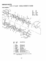
REPAIR PARTS
8 HP 21" TILLER
- - MODEL
NUMBER
917.299881
HANDLES
8
9
\.
4
6
\
2
2
%,,
%
%_
,
15
22
21
11
\
\
KEY
NO.
PART
NO.
1
2
3
4
5
6
7
8
9
138305
141406
110673X
127254X
6712J
137119
110641X
71191008
STD533125
10
11
t2
t3
14
15
16
17
t8
110646X
STD624003
81328
138295
109313X
138296
STD533710
109229X
STD541437
DESCRIPTION
KEY
NO.
PART
NO.
Throttle Control
Grip, Handle
Grommet, Handle
Bar, Drive Control Assembly
Cap, Vinyl
Panel, Control
Bushing, Split
Screw, Machine, Pan Head,#10-24
Bolt, Carriage
5/t6-18 UNC x 2-3/8 Grade 5
Handle, Grip
Clip, Hairpin
Bolt, Shoulder
Handle, Shift
Grommet, Rubber
Rod, Shift
Bolt, Carriage 3/8-16 x I Grade 5
Lock, Handle, Silver
Nut, Hex, Centerlock 3/8-16
19
20
21
22
23
19131611
109228X
138297
121145X
86777
24
25
26
27
28
29
30
9484R
73970500
138306
STD54t025
STD551125
STD541462
138283
NOTE:
\
DESCRIPTION
Washer 13/32 x i x 11 Gauge
Lever', Lock, Handle
Handle, Assemble
Clip, Plastic, Cable
Screw, Hex Washer Head, Slotted
#10-24 x 1/2
Clip
Locknut, Hex, Flange
Clutch, Cable
Nut, Hex 1/4-20
Washer, Lock 1/4
Nut, Hex, Keps #10-24
Lock, Handle, Black
All component dimensions given in U.S. inches.
I inch = 25.4 mm
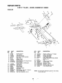
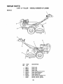
REPAIR PARTS
8 HP 21" TALLER - - MODEL NUMBER 917.299881
MAINFRAME,
LEFT SIDE
3
'16
13
17
27
15 22
%
KEY
NO.
PART
NO.
1
2
3
4
5
6
7
8
9
106t 60X
STD551137
S-fD541037
74930572
STD571810
110111X
STD532505
8700J
86777
10
1!
12
13
14
15
16
17
18
19
20
21
22
23
9484R
STD551125
STD541025
23230506
8382J
8TD55103I
100473M
STD541031
8381J
2649M
4914H
139155
104214)(
5015J
138417
795R
4929H
24
26
DESCRIPTION
33
O_Ring
Washer, Lock 3/8
Nut, Hex 3/8-16
Bolt, Hex Head 5116_18x 4-!/2
Pin, Roll
Lever, Shift
Bolt, Carriage 1/4-20 x 1/2 Grade 5
Plate, Shift Indicator
Screw, Hex Washer Head, Slotted
#10-24 x 1/2
Clip
Washer, Lock 1/4
Nut, Hex 1/4-20
Screw, Set, Hex 5/16d8 x3/8
Spacer, Split 0.327 x 0.42 x 2,68
Washer 11/32 x 11/16 x 16 Gauge
Sheave, Transmission
Nut, Hex 5/t6-18
Spacer
Key, Square 3/16 × 1-I/8
Key, Square
Spacer, Spl!t .523 x .718 x 2
Nut, Cap 5/16-18
Tire
Rim
Tire Valve
Rivet, Drilled
23
"-,.
KEY
NO.
25
26
27
28
29
30
31
32
33
34
35
PART
NO.
STD624003
102818X459
138399
104680X
I2000032
t0561IX
74770844
139401 "
STD551050
4368J
140062
25
DESCRIPTION
Clip, Hairpin
Guard, Belt
V-Belt
Pulley, Idler
Ring, Ktip
Bracket, Idler
Boit, Hex Head 1/2-20 x 2-3/4
Shaft, Idler Arm
Washer
Sheave, Engine
Cap Plunger
NOTE: AI1component dimensions given in UoS. inches°
1 inch = 25.4 mm
23
REPAIR PARTS
8 HP 21" TILLER - - MODEL NUMBER 917.299881
MAINFRAME,
RIGHT SIDE
17
\
16
8
5
KEY
NO.
PART
NO.
1
2
3
4
5
6
7
8
9
10
11
DESCRIPTION
KEY
NO.
PART
NO.
138402
73220500
10040500
74760528
138669
STD523710
8450J
STD551137
STD541037
STD533710
Bumper
Nut Fin Hex 5/16-18
Wash Lock Hvy HIcl 5/16
Bolt, Hex 5/16-18 x 1-3/4
Bracket, Engine
Bolt, Hex Head 3/8-16 x I
Counter' Weight, R.H°
Washer, Lock 3/8
Nut, Hex 3/8-16
Bolt, Carriage 3/8-16 x 1
12
13
4929H
5015J
138417
795R
72470636
STD523745
104164X
138401
STD624003
Clip, Hairpin
14
15
16
17
NOTE:
24
DESCRIPTION
Rivet, Drilled
Tire
Rim
Tire Valve
Bolt, Carriage 3t8-16 x 4-1/2
Bolt, Hex Head 3/8-16 x 4-1/2
Tie, Cable
Engine, Briggs & Str_tton, 8 HP,
Model Number 190402,
Type Number 6151-01
All component dimensions given in U.SJnches.
1 inch = 25.4 mm
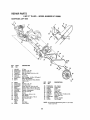
REPAIR PARTS
8 HP 21 " TILLER - - MODEL NUMBER 917.299881
TRANSMISSION
8
3
A
B
C
25
\
41
50
44
17 24
41
36
37
35
41
38
49
41
KEY
NO.
PART
NO.
I
142477
106!79X
2
3
4
5
6
7
8370J
8547J
8546J
100413K
674A29I
674A290
8
9
10
11
12
13
14
15
16
17
18
19
21
22
23
24
25
26
27
4358J
8358J
8371J
100371K
7392M
8353J
8354J
12000039
4360J
1370H
4895H
100724M
105378X
106181X
835&J
5020J
8372J
t06389X
100433M
DESCRIPTION
KEY
NO.
Transmission Assembly
Gearcase Assembly, R.H.
with Bearing (Includes Key No. 18)
Bolt, Upset
Gear, Reverse
Gear, Cluster, Red. 1st and 2nd
Bearing, Needle
Sprocket Assembly, Tine
Sprocket Assembly with Bearings
(Includes Key #6 & two of Key #5)
Washer
Shaft, Reduction, 1st
Chain, Roller, 60P
Spring, Shift, Fork
Bali, Steel
Fork, Shift
Shaft, Shift
Klip Ring
Washer, Seal
Race, Bearing, Thrust, 5/8 LD.
Bearing, Needle
Shaft, Input
Shaft Assembly, Tine
Spacer 1.008 x 1-3/4 x ,645
Pinion, Input
Bearing, Needle
Gasket, Gearcase
Spacer .765 InD.x 1.12 x 5/8
Gear, Cluster, Red.,, 2nd and 3rd
28
29
8357J
674A289
30
31
32
33
34
35
36
37
38
39
40
4I
42
43
44
6803J
12000O40
8356J
100016K
106392X
106394X
100436L
142145
106393X
7393R
14O576
9672R
STD551143
STD541143
109331X
45
46
47
48
49
50
--
74780512
8TD551131
STD541031
100107K
106391X
I02144X
6066J
PART
NO,
DESCRIPTION
Gear, Reverse Idler
Gear Assembly, Reverse Idler
(Includes Key Numbers 28 and 30)
Bearing, Needle
Klip Ring
Shaft, Reverse Idler
Shaft, Reduction, 2rid
Spacer .765 I.D. x 1-1/8 x 1-3/8
Spacer, Ground Drive, Loll.
Shaft Assembly, Ground
Assembly, Shift Bracket
Spacer, Ground Drive, R.H.
Seal, OiI
Seal, Ring, Rubber
Cup, Formed
Washer, Lock 7/16
Nut, Hex 7/16-20
Gearcase Assembly, L.Ho, with
Bearing (Includes Key Number 24)
Bolt, Hex Head 5/16-18 x 3/4
Washer, Lock 5/16
Nut, Hex Head 5/1648
Screw, Whiz-Lock 5/16-18 x 4
Spacer .765 IoD,x 1o12 x 3/4
Ring Retainer Spiral
Grease, Plastilub Number I
NOTE: All component dimensions given in UoS. inches
I inch = 25.4 mm
25
REPAIR PARTS
8 HP 21 " TILLER - - MODEL NUMBER 917.299881
TINE SHIELD
10
8
1
17
19
21
KEY
NO.
I
2
3
4
5
6
7
8
9
10
11
12
13
14
15
PART
NO.
98000129
10871tX459
8393J
12000036
72140508
8394J
8392J
109230X
104178X459
STD533107
STD541031
STD551131
10040400
8386J
108710X459
15
KEY
NO,
DESCRIPTION
16
17
18
19
20
21
22
23
24
25
26
27
28
Nut, Flange 5/16-18
Shield, Side, Outer, L.H.
Pin, Depth Stake
Ring, Klip
Boit, Carriage 5/16-18 x 1
Spring
Bracket, Latch
Spring, Depth Stake
Shield, Tine
Bolt, Carriage 5/16-t8 x 3/4 Gr. 5
Nut, Hex 5/16-18
Washer, Lock 5/t6
Washer Lock H,_ Helical 1/4
Bracket, Shield Tine
Shield, Side, Outer R,.H..
PART
NO.
73220400
104084X459
STD5325t2
8389J
STD541037
138420
74930656
4440J
72140408
6712J
109227X
102713X459
138609
DESCRIPTION
Nut Fin Hx 1/4-20
Shield, Side
Bolt, Carriage 1/4-20 x 1-1/4 Gr. 5
Grip
Nut, Hex 3/8-16
Stake, Depth
Bolt, Hex 3/8-16 x 2-1/2
Hinge
Bolt, Carriage 1/4-20 x 1/2 Gr. 5
Cap, Vinyl
Pad, Idler
Shield, Leveling
Pin, Hinge
NOTE: All component dimensions given in U.S. inches.
1 inch = 25.4 mm
26
@
BHP
9
.7
7
7
_g_
..
Bo_,_v. _,I_'_Z__S._ _
•-nr_oner_t
_en_-_o_S
REPAIR PARTS
8HP
21" TILLER - - MODEL NUMBER 917.299881
DECALS
1
2
8
7
KEY
NO.
1
2
3
4
5
6
7
8
9
PART
NO.
144971
138813
138263
138286
137538
120431X
138546
272698
120075X
144980
144981
DESCRIPTION
Decal, Logo
Decal, Logo
Decal, Logo
Decal, Logo
Decal, Caution, Drive Control
Decal, Hand Placement
Decal, Shift Indicator
Decal, Engine, HP
Decal, Warning, Rotating Tines
Manual, Owner's, English
Manual, Owner's, Spanish
28
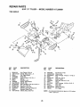
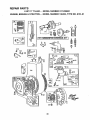
REPAIR PARTS
8 HP 21" TILLER -- MODEL NUMBER 917.299881
ENGINE, BRIGGS & STRATTON - - MODEL NUMBER 190402, TYPE NO.6151-01
t
635
354
14
337
307
308
7
383
8
10
•k REQUIRES SPECIAL TOOLS TO INSTALL.
SEE REPAIR INSTRUCTION MANUAL.
t_o_9
LABEL
K,T1
!3S8
GASKET
SE_I
29
REPAIR PARTS
8 HP 21" TILLER - - MODEL NUMBER 917.299881
ENGINE, BRIGGS & STRATTON -- MODEL NUMBER 190402, TYPE NO. 6151-01
[121 CARBURETOR
OVERHAUL
KIT i
50
45
53
41
I08
111 '_
68
332_
30
.
75
23
REPAIR PARTS
8 HP 21" TILLER -- MODEL NUMBER 917.299881
ENGINE, BRIGGS & STRATTON -- MODEL NUMBER 190402, TYPE NO.6151-01
KEY PART
NO. NO.
! 495631
2 495657
3 391086
5 214015
7 272163
8 39032'i
9 27803
10 94621
11 280267
12 271701
27876
27877
13 94565
14 93723
15 94720
94239
16 495648
94388
18 392818
19 295964
20 391086
21 66768
22 93585
23 298260
24 222698
25 391673
391674
391675
391676
26 391669
299743
391670
39"1671
391672
27 68546
28 295840
295841
29 390401
390773
30
32
33
34
35
36
37
38
4O
222113
92659
390419
94670
65906
26828
222475
93777
221596
KEY PART
NO. NO.
DESCRIPTION
DESCRIPTION
Rotocoil, Exhaust Valve
Retainer, Exhaust Valve Rotocoil(2)
Tappet, Valve
Gear, Cam
Elbow, intake
Gasket, Carburetor Mounting
Gasket, Intake Elbow Mounting
Screw, Shoulder
Screw, Seres, Carburetor Mounting
"93208 ....................
ScrewTItttake-Elbow
393576
Housing, Rewind Starter
295871
Pulley, Rewind Starter
490179
Spring, Rewind Starter
66884
Rope, Rewind Starter
490653
Insert, Starter Handle
490652
Handle, Rewind Starter
260414
Spring, Ratchet
230543
Adapter, Ratchet Spring
94128
Screw, Rewind Starter Housing
Mounting
Clutch Assembly, Rewind Starter
66 399671
Housing, Rewind Starter Clutch
67 394897
Ball, Clutch
68 63770
Ratchet, Rewind Starter Clutch
70 298799
Washer, Clutch Retaining
71 394506
Screen, Rewind Starter
73 221796
74 93758
Screw, Sems
75 224061
Washer, Spring
Carburetor Assembly,
90 390323
Manual Choke
Body Assembly, Upper Carburetor
91 399443
93 23108
Bushing, Throttle Shaft
** Valve Assembly, Carburetor Idle
94 292681
Screw, Seres,
95 93499
Throttle and Choke Valve Mounting
Valve, Throttle
96 22337O
Shaft and Lever, Throttle
97 298826
Screw, Fillister Head
98 91920
99 26157
Spring, Throttle Adjusting
I00 212904
Stop, Throttle
!0I 93043
** Pin, Throttle Stop
102 27918
Gasket, Carburetor Body
Cylinder Assembly
Bushing, Cylinder
* Seal, Oil
Head, Cylinder
* Gasket, Cylinder Head
Breather Assembly
* Gasket, Valve Cover
Screw, Seres
Tube, Breather
* Gasket, Crankcase Cover 1°/64"
* Gasket, Crankcase Cover °005"
* Gasket, Crankcase Cover .009"
Screw, Cylinder Head 3-9/16"
Screw, Cylinder Head 3"
Plug, Oil Drain, Flush
Plug, Oil Drain, Square Head
Crankshaft
Key, Timing Gear Retaining Device
Cover Assembly, Crankcase
Bushing, Crankcase
* Sea!, Oil
Plug, Oil Filler
Screw, Crankcase Cover
Flywheel, Magneto
Key, Flywheel
Piston Assembly, Standard Size
Piston Assembly ..010"Oversize
Piston Assembly .020" Oversize
Piston Assembly .030" Oversize
Ring Set, Piston, Standard Size
Ring Set, Piston, Chrome, Std. Size
Ring Set, Piston .010" Oversize
Ring Set, Piston .020" Oversize
Ring Set, Piston .030" Oversize
Lock, Piston Pin
Pin Assy. Piston, Standard Size
Pin Assy., Piston °005" Oversize
Rod Assembly, Connecting
Rod Assembly, Connecting,
.020" Undersize Crankpin Bore
Dipper, Connecting Rod
Screw, Connecting Rod
Valve, Exhaust
Valve, Intake
Spring, Intake Valve
Spring, Exhaust Valve
Guard, Flywheel
Screw, Seres
Retainer, Intake Valve
41
42
45
46
50
51
52
53
53A
54
55
56
57
58
59
60
63
64
65
*
**
292260
93630
260933
211689
212488
270684
27828
93956
93357
Included in Gasket Set, Part Number 299577
included in Carburetor Overhaul Kit, Part #398235
NOTE: Atl component dimensions given in U.S_ inches
1 inch = 25.4 mm
31
REPAIR PARTS
8 HP 21" TILLER
- - MODEL
NUMBER
917.299881
ENGINE, BRIGGS & STRATTON -- MODEL NUMBER 190402, TYPE NO. 6151-01
KEY PART
NO. NO.
103
104
105
107
108
109
110
111
112
113
114
116
118
99333
230896
394681
399442
62872
391987
222712
26155
23123
398202
68667
280203
99525
Includes:
119 94152
t21 398235
t64 398592
Uses:
165 94289
166 392105
167 65978
186 67218
187 296004
188 93535
200 221760
201 260872
209 261126
219 494845
220 221551
222 399151
227 391965
230 94742
265 221535
298 261409
300 393010
304 491596
305 94608
306 223374
307 93949
308 222636
332 92284
333 398811
334 93381
337 802592
346 93705
353 92791
KEY PART
NO. NO.
DESCRIPTION
Float, Carburetor
** Pin, Float Hinge
** Valve, Fuel Inlet
Body Assembly, Lower Carburetor
Valve, Choke
Shaft and Lever, Choke
Washer, Choke Lever
Spring, Choke Lever
Screw, Choke Lever
** Noz.zle;_Garburetor_.
...........
** Gasket, Nozzle
O-Ring, FuelValve
** Valve, Needle
22235
Washer, Brass
26336
Spring
65978
O-Ring
394033
Valve, Needle
Screw, Seres, Hex Head
Carburetor Overhaul Kit
Pipe Assembly, Air Cleaner
271265
O-Ring
Nut, Wing
Stud, Air Cleaner
Seal, Air Cleaner Stud
Connector, Fuel Pipe
Pipe, Fuel
Screw, Seres
Guide, Air
Link, Governor'
Spring, Governor
Gear-Governor
Washer, Thrust
Plate, Governor Control
Lever Assembly, Governor
Washer, Governor' Crank
Clamp, Casing
Locknut, Muffler
Muffler, Exhaust
Housing, Blower
Screw, Seres
Shield, Cylinder
Screw, Cylinder Shield
Cover, Cylinder Head
Nut
Armature, Magneto
Screw, Armature Mounting
Spark Plug
Screw, Sems
Washer, Lock
354 90576
356 398838
356A 398808
358 299577
363 19203
373 92987
383 89838
445 393957
467 493903
520-937_22
536 391063
552 491893
562 92613
592 231082
601 93053
608 390391
614 93306
615 93307
616 231057
621 396847
635 66538
642 222271
643 222272
655 222598
657 93496
676 393757
741 262479
843 280149
851 221798
869 211661
87t 231218
956 493337
957 493988
958 399517
959 223462
960 492990
96! 94095
985 398525
1016 490817
10!9 491181
DESCRIPTION
Nut, Hex
Wire, Ground
Wire, Ground
Gasket Set
Puller, Flywheel
Nut, Hex
Wrench, Spark Plug
Cartridge, Air Cleaner
Knob, Air Cleaner
.... Terminals-Spade ....
Air Cleaner Assembly
Bushing, Governor Crank
Bolt, Governor Lever
Nut, Hex
Clamp, Fuel Pipe
StarterAssembty, Rewind
Cotter' Pin
Retainer, E-Ring
Crank, Governor
Switch, Stop
Elbow, Spark Plug
Cover, Air Cleaner
Cup, AirCleaner
Anchor, Spring
Screw, Serns
Deflector', Exhaust
Gear', Timing
Sleeve, Choke Lever
Terminal, ignition Cable
Seat, Intake and Exhaust Valves
Guide, Intake and Exhaust Valves
Fuel Tank Assembly
Cap, Fuel Tank
Valve Assembly, Fuel Shut-Off
Bracket, Fuel Tank, Upper'
Bracket, Fuel Tank, Lower
Screw, Tank Mounting
Insulator Assembly
Spacer
Label Kit
RPM Settings: Low: 1750-1950, High: 3400-3600
*
**
Included in Gasket Set, Part Number' 299577
Included in Carburetor Overhaul Kit, Part #398235
NOTE: All component dimensions given in U.S. inches
1 inch = 25.4 mm
32
SERVICE NOTES
33
SERVICE N
34
SERVmCE NOTES
35
CRAFTSMANo
OWNER'S
MANUAL
MODEL NO.
917.299881
8.0 HP
21 INCH TINE WIDTH
REAR TINE TILLER WITH
COUNTER
Each tiller' has its own model number., Each engine has its own modet
number.
The model number for your tiller will be found on a plate attached to the
top of the transmission_
The model number for your engine will be found on the blower housing of
the engine.
IF YOU NEED
REPAIR SERVICE
OR PARTS:
FOR REPAIR SERVICE, CALL
THIS TOLL FREE NUMBER:
1-800-4-REPAIR
(1-800-473-7247)
FOR REPLACEMENT PARTS
INFORMATION AND
ORDERING, CALL THIS
TOLL FREE NUMBER:
1-800-FON-PART
(1-800-366-7278)
illll
i i iillll
All parts listed herein may be ordered from any Sears, Roebuck and Co.
Service Center/Department and most Retail Stores.
WHEN ORDERING REPAIR PARTS, ALWAYS GIVE THE FOLLOWING INFORMATION:
• PRODUCT - REAR TINE TILLER
• MODEL NUMBER - 917.29988I
• ENGINE MODEL NUMBER- 190402, TYPE NUMBER 6151-01
° PART NUMBER
° PART DESCRIPTION
Your Sears merchandise has added value when you consider Sears has
service units nationwide staffed with Sears trained technicians.., professional technicians specifically trained to insure that we meet our pledge
to you, we service what we sell.
illl ii
Sears, Roebuck and Co., Hoffman Estates, IL 60179 U.S.A.
......................................................................
144980
REV. 1 5°3°94
i
PRINTED IN THE UoS.,A.