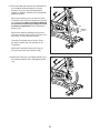
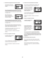
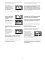
1
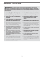
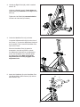
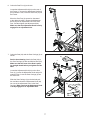
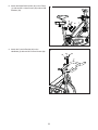
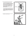
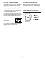
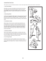
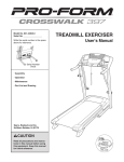
www.proform.com
Model No. PFEX64011.0
Serial No.
Write the serial number in the space
above for reference.
Serial Number
Decal
QUESTIONS?
If you have questions, or if parts
are damaged or missing, DO NOT
CONTACT THE STORE; please
contact Customer Care.
IMPORTANT: Please register this
product (see the limited warranty
on the back cover of this manual)
before contacting Customer Care.
CALL TOLL-FREE:
1-888-533-1333
Mon.–Fri., 6 a.m.–6 p.m. MT
Sat. 8 a.m.–4 p.m. MT
ON THE WEB:
www.proformservice.com
CAUTION
Read all precautions and instructions in this manual before using
this equipment. Keep this manual
for future reference.
USER’S MANUAL
TABLE OF CONTENTS
WARNING DECAL PLACEMENT . . . . . . . . . . . . . . . . . . . . . . . . . . . . . . . . . . . . . . . . . . . . . . . . . . . . . . . . . . . . . . . 2
IMPORTANT PRECAUTIONS . . . . . . . . . . . . . . . . . . . . . . . . . . . . . . . . . . . . . . . . . . . . . . . . . . . . . . . . . . . . . . . . . . 3
BEFORE YOU BEGIN. . . . . . . . . . . . . . . . . . . . . . . . . . . . . . . . . . . . . . . . . . . . . . . . . . . . . . . . . . . . . . . . . . . . . . . . 4
ASSEMBLY . . . . . . . . . . . . . . . . . . . . . . . . . . . . . . . . . . . . . . . . . . . . . . . . . . . . . . . . . . . . . . . . . . . . . . . . . . . . . . . . 5
HOW TO USE THE EXERCISE BIKE . . . . . . . . . . . . . . . . . . . . . . . . . . . . . . . . . . . . . . . . . . . . . . . . . . . . . . . . . . . 12
EXERCISE GUIDELINES . . . . . . . . . . . . . . . . . . . . . . . . . . . . . . . . . . . . . . . . . . . . . . . . . . . . . . . . . . . . . . . . . . . . 19
PART LIST. . . . . . . . . . . . . . . . . . . . . . . . . . . . . . . . . . . . . . . . . . . . . . . . . . . . . . . . . . . . . . . . . . . . . . . . . . . . . . . . 22
EXPLODED DRAWING. . . . . . . . . . . . . . . . . . . . . . . . . . . . . . . . . . . . . . . . . . . . . . . . . . . . . . . . . . . . . . . . . . . . . . 23
ORDERING REPLACEMENT PARTS . . . . . . . . . . . . . . . . . . . . . . . . . . . . . . . . . . . . . . . . . . . . . . . . . . Back Cover
LIMITED WARRANTY. . . . . . . . . . . . . . . . . . . . . . . . . . . . . . . . . . . . . . . . . . . . . . . . . . . . . . . . . . . . . . . Back Cover
WARNING DECAL PLACEMENT
This drawing shows the location(s) of the warning
decal(s). If a decal is missing or illegible, see
the front cover of this manual and request a
free replacement decal. Apply the decal in the
location shown. Note: The decal(s) may not be
shown at actual size.
PROFORM is a registered trademark of ICON IP, Inc.
2
IMPORTANT PRECAUTIONS
WARNING:
To reduce the risk of serious injury, read all important precautions and
instructions in this manual and all warnings on your exercise bike before using your exercise bike.
ICON assumes no responsibility for personal injury or property damage sustained by or through the
use of this product.
1. Before beginning any exercise program,
consult your physician. This is especially
important for persons over age 35 or persons with pre-existing health problems.
9. Wear appropriate clothes while exercising;
do not wear loose clothes that could become
caught on the exercise bike. Always wear
athletic shoes for foot protection.
2. Use the exercise bike only as described in
this manual.
10. The exercise bike should not be used by
persons weighing more than 275 lbs.
(125 kg).
3. It is the responsibility of the owner to ensure
that all users of the exercise bike are adequately informed of all precautions.
11. Always keep your back straight while using
the exercise bike; do not arch your back.
12. The exercise bike does not have a freewheel;
the pedals will continue to move until the
flywheel stops. Reduce your pedaling speed
in a controlled way.
4. The exercise bike is intended for home use
only. Do not use the exercise bike in a commercial, rental, or institutional setting.
5. Keep the exercise bike indoors, away from
moisture and dust. Do not put the exercise
bike in a garage or covered patio, or near
water.
13. To stop the flywheel quickly, press the brake
lever downward.
14. When the exercise bike is not in use, tighten
the resistance knob completely to prevent
the flywheel from moving.
6. Place the exercise bike on a level surface
with at least 2 ft. (0.6 m) of clearance around
the exercise bike. To protect the floor or
carpet from damage, place a mat under the
exercise bike.
15. To avoid damaging the brake pads, do not
lubricate the brake pads.
16. Over exercising may result in serious injury
or death. If you feel faint or if you experience
pain while exercising, stop immediately and
cool down.
7. Inspect and properly tighten all parts regularly. Replace any worn parts immediately.
8. Keep children under age 12 and pets away
from the exercise bike at all times.
3
BEFORE YOU BEGIN
Thank you for selecting the new PROFORM® 315
IC exercise bike. Cycling is an effective exercise for
increasing cardiovascular fitness, building endurance,
and toning the body. The 315 IC exercise bike provides a selection of features designed to make your
workouts at home more effective and enjoyable.
reading this manual, please see the front cover of this
manual. To help us assist you, note the product model
number and serial number before contacting us. The
model number and the location of the serial number
decal are shown on the front cover of this manual.
Before reading further, please familiarize yourself with
the parts that are labeled in the drawing below.
For your benefit, read this manual carefully before
you use the exercise bike. If you have questions after
Resistance Knob
Brake Lever
Console
Handlebar
Seat
Adjustment Knobs
Adjustment Knob
Water Bottle Holder
Pedal/Strap
Transmitter
Wheel
Leveling Foot
Leveling Foot
4
ASSEMBLY
• Assembly requires two persons.
• In addition to the included tool(s), assembly
requires the following tools:
• Place all parts in a cleared area and remove the
packing materials. Do not dispose of the packing
materials until you complete all assembly steps.
one Phillips screwdriver
one adjustable wrench
• Assembly may be easier if you have your own set
of wrenches. To avoid damaging parts, do not use
power tools.
1. Remove the two screws, the two washers, and
the shipping bracket (not shown) from the rear of
the Frame (1) if necessary. Discard the screws,
washers, and shipping bracket.
1
Identify the Rear Stabilizer (7), which does not
have wheels.
25
Tighten two Leveling Feet (16) and two M10
Hex Nuts (49) into the underside of the Rear
Stabilizer (7).
24
1
Attach the Rear Stabilizer (7) to the Frame (1)
with two M8 x 16mm Screws (25) and two M8
Washers (24).
7
49
16
49
16
2. Remove the two screws, the two washers, and
the shipping bracket (not shown) from the front
of the Frame (1). Discard the screws, washers,
and shipping bracket.
2
Orient the Front Stabilizer (8) so that the Wheels
(21) are in the position shown.
25
24
25
Attach the Front Stabilizer (8) to the Frame (1)
with two M8 x 16mm Screws (25) and two M8
Washers (24).
24
1
21
8
21
5
3. Identify the Right Pedal (35), which is marked
with an “R.”
3
Using an adjustable wrench, firmly tighten the
Right Pedal (35) clockwise into the Right Crank
Arm (31).
Tighten the Left Pedal (38) counterclockwise
into the Left Crank Arm (not shown).
31
35
38
4. Orient the Handlebar Post (4) as shown.
4
Locate the Adjustment Knob (23) on the front of
the Frame (1). Loosen the Adjustment Knob and
pull it outward. Then, insert the Handlebar Post
(4) into the Frame.
4
Move the Handlebar Post (4) upward or
downward to the desired position, release
the Adjustment Knob (23) into an adjustment
hole in the Handlebar Post, and then tighten
the Adjustment Knob. Make sure that the
Adjustment Knob is firmly engaged in an
adjustment hole.
1
23
5. Attach the Handlebar (5) to the Handlebar Post
(4) with two M10 x 25mm Screws (34) and two
M10 Washers (33).
5
34
5
33
4
6
6. Orient the Seat Post (2) as shown.
6
Locate the Adjustment Knob (23) on the rear of
the Frame (1). Loosen the Adjustment Knob and
pull it outward. Then, insert the Seat Post (2) into
the Frame.
Move the Seat Post (2) upward or downward
to the desired position, release the Adjustment
Knob (23) into an adjustment hole in the Seat
Post, and then tighten the Adjustment Knob.
Make sure that the Adjustment Knob is firmly
engaged in an adjustment hole.
2
23
1
7. Orient the Seat (22) and the Seat Carriage (3) as
shown.
7
22
See the inset drawing. Attach the Seat (22) to
the Seat Carriage (3) with two M8 Hex Nuts (55).
Make sure that the nose of the Seat is pointing straight ahead before you tighten the Hex
Nuts.
2
23
Locate the Adjustment Knob (23) on the Seat
Post (2). Loosen the Adjustment Knob and pull it
outward. Then, insert the Seat Carriage (3) into
the Seat Post.
Slide the Seat Carriage (3) to the desired position and then release the Adjustment Knob (23)
into one of the adjustment holes in the Seat
Carriage. Make sure that the Adjustment Knob
is firmly engaged in an adjustment hole.
3
22
3
55
7
8. Attach the Water Bottle Holder (60) to the Frame
(1) with two M5 x 12mm Screws (39) and two M5
Washers (52).
8
39 52
1
60
9. Attach the Console Bracket (64) to the
Handlebar (5) with two M5 x 12mm Screws (39).
9
39
64
39
5
8
10. The Console (68) requires two AAA batteries
(not included); alkaline batteries are recommended. Do not use old and new batteries
together or alkaline, standard, and rechargeable
batteries together. IMPORTANT: If the Console
has been exposed to cold temperatures,
allow it to warm to room temperature before
you insert batteries. Otherwise, you may
damage the console display or other electronic components.
10
68
Battery
Compartment
Remove the battery cover from the back of the
Console (68), and insert batteries into the battery
compartment. Make sure that the batteries are
oriented as shown by the diagrams inside the
battery compartment. Then, reattach the battery cover.
11. Attach the Console (68) to the Console Bracket
(64) with a Console Screw (65).
11
68
64
65
9
12. The Transmitter (63) requires two AAA batteries
(not included); alkaline batteries are recommended. Do not use old and new batteries
together or alkaline, standard, and rechargeable
batteries together.
12
Remove the battery cover from the front of the
Transmitter (63), and insert batteries into the battery compartment. Make sure that the batteries
are oriented as shown by the diagrams inside
the battery compartment. Then, reattach the
battery cover.
62
Battery
Cover
Remove the adhesive backing from the Hook
and Loop Fasteners (62). Press a Fastener onto
the Frame (1) in the indicated location.
1
Orient the Transmitter (63) as shown. Press
the other Fastener (62) onto the back of the
Transmitter.
Attach the Transmitter (63) to the Frame (1)
using the Hook and Loop Fasteners (62).
13. Attach the Clamp (67) to the Right Shield (14) in
the indicated location with a Self-tapping Screw
(13).
63
13
14
13
67
10
14. Plug the Reed Switch (61) into the Transmitter
(63).
14
Insert the other end of the Reed Switch (61) into
the Clamp (67).
Rotate the Flywheel (36) until the Magnet (66) is
aligned with the end of the Reed Switch (61).
67
36
66
Move the Reed Switch (61) so that the gap
between the Reed Switch and the Magnet (66) is
about 1/8 in. (3 mm).
61
63
15. Make sure that all parts are properly tightened before you use the exercise bike. Note: After assembly is
completed, some extra parts may be left over. Place a mat beneath the exercise bike to protect the floor.
If you purchase the optional heart rate monitor (see page 18), follow the step below to install the
receiver included with the heart rate monitor.
16. See step 11 on page 9 and remove the
Console (68) from the Console Bracket (64).
16
B
Remove the three screws from the back cover
(A) of the Console (68), and then remove the
back cover.
Antenna
A
Connect the wire on the receiver (B) to the wire
in the Console (68). Hold the receiver so that
the antenna is oriented as shown and is facing upward.
Wires
68
Attach
receiver
here
Remove the paper from the adhesive pad on the
back of the receiver (B). Press the receiver onto
the console in the indicated location. Then, reattach the back cover (A).
Reattach the Console (68) to the Console
Bracket (64).
Note: Discard any other wires that are included
with the heart rate monitor.
11
HOW TO USE THE EXERCISE BIKE
HOW TO ADJUST THE ANGLE OF THE SEAT
HOW TO ADJUST THE SEAT POST
You can adjust the angle of the seat to the position that
is most comfortable. You can also slide your seat forward or backward to increase your comfort or to adjust
the distance to the handlebar.
For effective exercise, the seat should be at the proper
height. As you pedal, there should be a slight bend in
your knees when the pedals are in the lowest position.
To adjust the height
of the seat post, first
loosen the adjustment knob and pull it
outward. Then, move
Adjustment
the seat post upward
Seat
Knob
or downward, release
Post
the adjustment knob
into an adjustment
hole in the seat post,
and firmly tighten the adjustment knob. Make sure that
the adjustment knob is engaged in an adjustment
hole.
To adjust the seat, see the inset drawing in assembly
step 7 on page 7. Loosen the nuts on the seat
clamp a few turns, and then tilt the seat upward or
downward or slide the seat forward or backward to the
desired position. Then, retighten the nuts.
HOW TO ADJUST THE HORIZONTAL POSITION OF
THE SEAT
To adjust the position of the seat, first
Seat
loosen the adjustment knob and pull
it downward. Then,
move the seat forAdjustment
ward or backward,
Knob
release the adjustment knob into an
adjustment hole in the seat carriage, and firmly tighten
the adjustment knob. Make sure that the adjustment
knob is engaged in an adjustment hole.
HOW TO ADJUST THE HANDLEBAR POST
To adjust the height
of the handlebar
Handlebar
post, first loosen the
Post
adjustment knob and
pull it outward. Then,
move the handlebar
post upward or downAdjustment
Knob
ward, release the
adjustment knob into
an adjustment hole
in the handlebar post, and firmly tighten the adjustment knob. Make sure that the adjustment knob is
engaged in an adjustment hole.
12
HOW TO ADJUST THE PEDAL STRAPS
HOW TO LEVEL THE EXERCISE BIKE
To tighten the pedal straps (see the drawing on page
4), simply pull the ends of the pedal straps. To
loosen the pedal straps, press and hold the tabs on the
buckles, adjust the pedal straps to the desired position,
and then release the tabs.
If the exercise bike rocks slightly on your floor during
use, turn one or both of the leveling feet on the front or
rear stabilizer (see the drawing on page 4) until the
rocking motion is eliminated.
HOW TO MAINTAIN THE EXERCISE BIKE
HOW TO ADJUST THE PEDALING RESISTANCE
To increase the resistance of the pedals,
turn the resistance
knob clockwise;
to decrease the
resistance, turn the
resistance knob
counterclockwise.
Inspect and tighten all parts of the exercise bike regularly. Replace any worn parts immediately.
Resistance
Knob
To clean the exercise bike, use a damp cloth and a
small amount of mild detergent. IMPORTANT: To
avoid damage to the console, keep liquids away
from the console and keep the console out of
direct sunlight.
Brake
Lever
HOW TO ADJUST THE REED SWITCH
To stop the flywheel, push the brake lever downward. The flywheel should quickly come to a
complete stop.
If the console does not display correct feedback, the
reed switch should be adjusted. To adjust the reed
switch, see the drawing in assembly step 14 on page
11.
IMPORTANT: When the exercise bike is not in use,
tighten the resistance knob completely.
Rotate the flywheel until the magnet is aligned with
the reed switch. Slide the reed switch slightly toward
or away from the magnet. Then, rotate the flywheel
for a moment. Repeat these actions until the console
displays correct feedback.
13
CONSOLE DIAGRAM
HOW TO PERSONALIZE CONSOLE SETTINGS
1. Turn on the console.
Press any button to turn on the console.
2. Enter the setup mode.
First, press the Left button
repeatedly until the word
SPEED appears in the
lower display.
Then, press and hold the Right button for several
seconds to enter the setup mode.
Note: The console will exit the setup mode automatically if several seconds pass and no buttons
are pressed.
3. Set a time goal if desired.
Left
Button
When you enter the setup
mode, the minutes place
in the lower display will
flash.
Right
Button
FEATURES OF THE CONSOLE
To set a time goal for
your workout, press the
Right button repeatedly to
select the desired number
of minutes. To select a
time goal quickly, press
and hold down the Right button.
The console offers a selection of features designed
to provide instant exercise feedback and make your
workouts more effective.
The console features a heart rate alarm that helps you
keep your heart rate within your selected target heart
rate zone while you exercise. Note: To use this feature,
you must wear an optional heart rate monitor (see
page 18).
Note: You can set a time goal between 1 and 99
minutes.
Note: If you set a time goal, the lower display will
count down the time remaining in your workout
instead of the elapsed time (see step 3 of HOW TO
USE THE CONSOLE on page 16).
The console also allows you to personalize settings,
select a system of measurement, and enter user information before you begin exercising.
To personalize console settings, see the instructions
at the right. To set the clock, see page 16. To use
the console, see page 16. To use the heart rate
alarm, see page 18.
Press the Left button to advance to the next
setting.
Before using the console, make sure that batteries
are installed in the console and the transmitter (see
assembly step 10 on page 9 and assembly step
12 on page 10). If there is a sheet of plastic on the
display, remove the plastic.
14
4. Define the target heart rate zone if desired.
6. Select a unit of measurement if desired.
The maximum heart rate
will flash in the middle left
display.
The console can display speed, distance, and
weight in standard or metric measurements.
The letters Lb (standard)
or Kg (metric) will flash in
the lower display to show
which unit of measurement is selected.
To set the maximum heart rate, press the Right
button repeatedly to select the desired heart rate.
To select a heart rate quickly, press and hold down
the Right button.
Press the Right button repeatedly to select the
desired unit of measurement.
Next, press the Left
button. The minimum
heart rate will flash in the
middle left display.
Press the Left button to advance to the next
setting.
7. Enter your weight if desired.
To set the minimum heart rate, press the Right
button repeatedly to select the desired heart rate.
To select a heart rate quickly, press and hold down
the Right button.
A weight setting will flash
in the lower display.
Note: You must define a target heart rate zone to
use the heart rate alarm (see HOW TO USE THE
HEART RATE ALARM on page 18).
Press the Right button
repeatedly to select your
weight. To select your
weight quickly, press and
hold down the Right
button.
To determine your target heart rate zone, see
EXERCISE INTENSITY on page 19.
Press the Left button to advance to the next
setting.
Note: You can select a weight setting between
44 and 396 pounds or between 20 and 180 kilograms. The exercise bike should not be used by
persons weighing more than 275 pounds or 125
kilograms.
5. Enter your gender if desired.
A gender symbol will flash
in the lower display.
8. Exit the setup mode at any time.
The console will exit the setup mode automatically if several seconds pass and no buttons are
pressed.
Press the Right button repeatedly to select the
symbol that represents your gender.
Note: To advance again through the settings
described in steps 3 to 7, press the Left button
repeatedly.
Press the Left button to advance to the next
setting.
15
HOW TO SET THE CLOCK
HOW TO USE THE CONSOLE
1. Turn on the console.
1. Turn on the console.
Press any button to turn on the console.
Press any button to turn on the console.
2. Wear an optional heart rate monitor if desired.
2. Enter the clock mode.
First, press the Left button
repeatedly until the clock
symbol appears in the
lower display.
To display your heart rate (see step 3) or use the
heart rate alarm (see HOW TO USE THE HEART
RATE ALARM on page 18), you must wear an
optional heart rate monitor (see page 18).
3. Follow your progress with the displays.
Then, press and hold the Right button for several
seconds to enter the clock mode.
The upper left display—
As you pedal, the rpm
meter in this display indicates your approximate
pedaling speed in revolutions per minute (rpm) in
a range from 0 rpm to 200 rpm. Bars will appear or
disappear in increments as you change your pedaling speed.
Note: The console will exit the clock mode automatically if several seconds pass and no buttons
are pressed.
3. Change the time notation if desired.
The time notation will
flash in the middle right
display.
The upper right display—This display shows your
pedaling speed in revolutions per minute (rpm) in a
range from 0 rpm to 240 rpm.
Press the Right button repeatedly to select the
desired time notation. Select 12H for a 12-hour
clock. Select 24H for a 24-hour clock.
Note: When you stop pedaling, this display shows
the average pedaling speed (AVG rpm) for your
workout.
4. Set the time.
The middle left
display—This display
shows your heart rate
(heart symbol) in beats
per minute (bpm) in a
range from 0 to 240 bpm
when you wear an optional heart rate monitor (see
page 18).
Press the Left button to
select the hour setting.
The hour setting will flash
in the lower display.
Press the Right button repeatedly to select the
desired hour setting. Make sure to select the correct am or pm setting when you select the hour
setting.
The middle right display—This display shows the
approximate number of calories (KCAL) you have
burned.
Press the Left button to select the minute setting.
The minute setting will flash in the lower display.
Press the Right button repeatedly to select the
desired minute setting.
5. Exit the clock mode at any time.
The console will exit the clock mode automatically if several seconds pass and no buttons are
pressed.
16
The lower display—This display can show the following workout information:
To turn on the console backlight for a few seconds,
press the Right button once at any time.
Speed (SPEED)—This
display shows your pedaling speed in miles per
hour (ML/H) or kilometers
per hour (KM/H).
Note: The console can display speed and distance in either miles or kilometers. The letters
ML/H or KM/H will appear in the display to show
which unit of measurement is selected. To change
the unit of measurement, see step 6 on page 15.
Note: When you stop pedaling, this display shows
the average pedaling speed (AVG SPEED) for your
workout.
4. Set a time goal, if desired.
To set a time goal, see step 3 on page 14.
Distance (DIST)—This
display shows the distance you have pedaled
in miles (ML) or kilometers (KM).
To clear the time goal, press the Left button
repeatedly until the word TIME appears in the
lower display. Then, press and hold the Right button until zeros appear in the lower display.
Note: If you set a time goal, the lower display will
count down the time remaining in your workout
instead of the elapsed time.
Time (TIME)—This display shows the elapsed
time in a range from 0
minutes to 99 minutes.
When you reach your goal, a tone will sound for
several seconds. Then, the console will begin to
count the elapsed time.
Note: If you set a time
goal (see step 4), this display shows the time
remaining in your workout instead of the elapsed
time.
5. Measure your heart rate if desired.
To display your heart rate, you must wear an
optional heart rate monitor (see page 18).
Clock (Clock symbol)—This display shows
the time of day using
a 12-hour clock or a
24-hour clock.
When your heart rate
is detected, the heart
symbol will flash and your
heart rate will be shown in
the middle left display.
Press the Left button repeatedly until the lower
display shows the workout information you are
interested in viewing.
6. When you are finished exercising, the console
will turn off automatically.
To reset the displays, press the Left button repeatedly until the word TIME appears in the lower
display. Then, press and hold the Right button until
zeros appear in the displays.
The console has an “auto-off” feature. If the pedals
do not move and the buttons are not pressed for a
few minutes, the power will turn off automatically to
save the batteries.
17
HOW TO USE THE HEART RATE ALARM
THE OPTIONAL HEART RATE MONITOR
The heart rate alarm will alert you when your heart rate
is below or above a defined target heart rate zone.
Whether your goal is to burn fat or to strengthen your
cardiovascular system, the key to achieving the best
results is to maintain the proper heart rate during you
workouts. The optional chest heart rate monitor will
enable you to continuously monitor your heart rate
while you exercise, helping you to reach your personal
fitness goals. To purchase a chest heart rate monitor, please see the front cover of this manual.
IMPORTANT: You must wear an optional heart
rate monitor to use the heart rate alarm (see THE
OPTIONAL HEART RATE MONITOR at the right).
To use the heart rate alarm, first see step 4 on page
15 and define a target heart rate zone.
As you pedal, the console will regularly compare your
heart rate to the target heart rate zone and will indicate
if your heart rate is too far below or above the target
heart rate zone.
When a downward-pointing
arrow flashes in the middle
left display, increase your
pedaling speed.
When an upward-pointing arrow flashes in the middle
left display, decrease your pedaling speed.
IMPORTANT: The heart rate alarm is intended only
to provide motivation. Make sure to pedal at a
speed that is comfortable for you.
18
EXERCISE GUIDELINES
Burning Fat—To burn fat effectively, you must exercise at a low intensity level for a sustained period of
time. During the first few minutes of exercise, your
body uses carbohydrate calories for energy. Only after
the first few minutes of exercise does your body begin
to use stored fat calories for energy. If your goal is to
burn fat, adjust the intensity of your exercise until your
heart rate is near the lowest number in your training
zone. For maximum fat burning, exercise with your
heart rate near the middle number in your training
zone.
WARNING:
Before beginning this
or any exercise program, consult your physician. This is especially important for persons
over age 35 or persons with pre-existing
health problems.
The heart rate monitor is not a medical device.
Various factors may affect the accuracy of
heart rate readings. The heart rate monitor is
intended only as an exercise aid in determining heart rate trends in general.
Aerobic Exercise—If your goal is to strengthen your
cardiovascular system, you must perform aerobic
exercise, which is activity that requires large amounts
of oxygen for prolonged periods of time. For aerobic
exercise, adjust the intensity of your exercise until your
heart rate is near the highest number in your training
zone.
These guidelines will help you to plan your exercise
program. For detailed exercise information, obtain a
reputable book or consult your physician. Remember,
proper nutrition and adequate rest are essential for
successful results.
WORKOUT GUIDELINES
EXERCISE INTENSITY
Warming Up—Start with 5 to 10 minutes of stretching and light exercise. A warm-up increases your body
temperature, heart rate, and circulation in preparation
for exercise.
Whether your goal is to burn fat or to strengthen your
cardiovascular system, exercising at the proper intensity is the key to achieving results. You can use your
heart rate as a guide to find the proper intensity level.
The chart below shows recommended heart rates for
fat burning and aerobic exercise.
Training Zone Exercise—Exercise for 20 to 30 minutes with your heart rate in your training zone. (During
the first few weeks of your exercise program, do not
keep your heart rate in your training zone for longer
than 20 minutes.) Breathe regularly and deeply as you
exercise—never hold your breath.
Cooling Down—Finish with 5 to 10 minutes of stretching. Stretching increases the flexibility of your muscles
and helps to prevent post-exercise problems.
EXERCISE FREQUENCY
To find the proper intensity level, find your age at the
bottom of the chart (ages are rounded off to the nearest ten years). The three numbers listed above your
age define your “training zone.” The lowest number is
the heart rate for fat burning, the middle number is the
heart rate for maximum fat burning, and the highest
number is the heart rate for aerobic exercise.
To maintain or improve your condition, complete three
workouts each week, with at least one day of rest
between workouts. After a few months of regular exercise, you may complete up to five workouts each week,
if desired. Remember, the key to success is to make
exercise a regular and enjoyable part of your everyday
life.
19
SUGGESTED STRETCHES
The correct form for several basic stretches is shown at the right. Move slowly as you stretch—never bounce.
1. Toe Touch Stretch
Stand with your knees bent slightly and slowly bend forward from
your hips. Allow your back and shoulders to relax as you reach
down toward your toes as far as possible. Hold for 15 counts, then
relax. Repeat 3 times. Stretches: Hamstrings, back of knees and
back.
1
2. Hamstring Stretch
2
Sit with one leg extended. Bring the sole of the opposite foot toward
you and rest it against the inner thigh of your extended leg. Reach
toward your toes as far as possible. Hold for 15 counts, then relax.
Repeat 3 times for each leg. Stretches: Hamstrings, lower back and
groin.
3. Calf/Achilles Stretch
With one leg in front of the other, reach forward and place your
hands against a wall. Keep your back leg straight and your back
foot flat on the floor. Bend your front leg, lean forward and move
your hips toward the wall. Hold for 15 counts, then relax. Repeat
3 times for each leg. To cause further stretching of the achilles
tendons, bend your back leg as well. Stretches: Calves, achilles
tendons and ankles.
3
4
4. Quadriceps Stretch
With one hand against a wall for balance, reach back and grasp
one foot with your other hand. Bring your heel as close to your buttocks as possible. Hold for 15 counts, then relax. Repeat 3 times for
each leg. Stretches: Quadriceps and hip muscles.
5. Inner Thigh Stretch
Sit with the soles of your feet together and your knees outward.
Pull your feet toward your groin area as far as possible. Hold for 15
counts, then relax. Repeat 3 times. Stretches: Quadriceps and hip
muscles.
20
5
NOTES
21
PART LIST
Key No. Qty.
1
2
3
4
5
6
7
8
9
10
11
12
13
14
15
16
17
18
19
20
21
22
23
24
25
26
27
28
29
30
31
32
33
34
35
1
1
1
1
1
2
1
1
1
1
1
1
8
1
1
4
3
4
3
1
2
1
3
4
4
2
1
1
1
1
1
2
2
2
1
Model No. PFEX64011.0 R0911A
Description
Key No. Qty.
Frame
Seat Post
Seat Carriage
Handlebar Post
Handlebar
M12 Flange Nut
Rear Stabilizer
Front Stabilizer
Brake Lever
Plastic Spacer
Resistance Knob
Left Crank Arm
Self-tapping Screw
Right Shield
Left Shield
Leveling Foot
Post Bushing
Stabilizer Cap
Post Cap
Shield Cover
Wheel
Seat
Adjustment Knob
M8 Washer
M8 x 16mm Screw
6.5mm Plastic Spacer
M6 x 38mm Bolt
Chain
M6 Locknut
Crank Hub
Right Crank Arm/Crank Wheel
Crank Cap
M10 Washer
M10 x 25mm Screw
Right Pedal/Strap
36
37
38
39
40
41
42
43
44
45
46
47
48
49
50
51
52
53
54
55
56
57
58
59
60
61
62
63
64
65
66
67
68
*
*
1
1
1
4
2
2
1
1
2
1
4
1
2
4
2
1
2
2
2
2
1
1
1
2
1
1
1
1
1
1
1
1
1
–
–
Description
Flywheel
Flywheel Hub Set
Left Pedal/Strap
M5 x 12mm Screw
M8 Locknut
Brake Pad
Brake Clamp
Knob Washer
Brake Cable
Caliper Brake
Wheel Bearing
Flywheel Sprocket
Brake Pad Mount
M10 Hex Nut
M8 Bolt
M6 x 40mm Bolt
M5 Washer
Crank Nut
M5 x 25mm Screw
M8 Hex Nut
M6 Flange Nut
Flywheel Ring
M10 Locknut
M5 x 12mm Screw
Water Bottle Holder
Reed Switch
Hook and Loop Fastener
Transmitter
Console Bracket
Console Screw
Magnet
Clamp
Console
Assembly Tool
User’s Manual
Note: Specifications are subject to change without notice. For information about ordering replacement parts, see
the back cover of this manual. *These parts are not illustrated.
22
EXPLODED DRAWING
Model No. PFEX64011.0 R0911A
22
34
55
55
17
33
23
19
68
39
64
3
39
5
65
2
11
43
19
9 10
17
18
25
7
24
16
18
49
16
29
38
4
38
19
17
27
23 39
52 42
44
58
12
60
61
51
41
15 26
38
23
56
49
32
53
63
45
48
25
62
54
35
24
6
30
35
18
1
18
31
8
40
28
50
47
32 53
35
36
16
66
37
6
13
13
67
57
49
14
20
13
59
13
23
40
49
50
46
16 46 21
46
21
46
ORDERING REPLACEMENT PARTS
To order replacement parts, please see the front cover of this manual. To help us assist you, be prepared to
provide the following information when contacting us:
• the model number and serial number of the product (see the front cover of this manual)
• the name of the product (see the front cover of this manual)
• the key number and description of the replacement part(s) (see the PART LIST and the EXPLODED
DRAWING near the end of this manual)
LIMITED WARRANTY
IMPORTANT: You must register this product within 30 days of the purchase date to avoid added
fees for service needed under warranty. Go to www.proformservice.com/registration.
ICON Health & Fitness, Inc. (ICON) warrants this product to be free from defects in workmanship and
material, under normal use and service conditions. The frame is warranted for five (5) years. Parts and
labor are warranted for one (1) year from the date of purchase.
This warranty extends only to the original purchaser (customer). ICON’s obligation under this warranty is
limited to repairing or replacing, at ICON’s option, the product through one of its authorized service centers.
All repairs for which warranty claims are made must be preauthorized by ICON. If the product is shipped
to a service center, freight charges to and from the service center will be the customer’s responsibility. If
replacement parts are shipped while the product is under warranty, the customer will be responsible for a
minimal handling charge. For in-home service, the customer will be responsible for a minimal trip charge.
This warranty does not extend to freight damage to the product. This warranty will automatically be voided
if the product is used as a store display model, if the product is purchased or transported outside the USA,
if all instructions in this manual are not followed, if the product is abused or improperly or abnormally used,
or if the product is used for commercial or rental purposes. No other warranty beyond that specifically set
forth above is authorized by ICON.
ICON is not responsible or liable for indirect, special, or consequential damages arising out of or in connection with the use or performance of the product; damages with respect to any economic loss, loss of
property, loss of revenues or profits, loss of enjoyment or use, or costs of removal or installation; or other
consequential damages of any kind. Some states do not allow the exclusion or limitation of incidental or
consequential damages. Accordingly, the above limitation may not apply to the customer.
The warranty extended hereunder is in lieu of any and all other warranties, and any implied warranties of
merchantability or fitness for a particular purpose are limited in their scope and duration to the terms set
forth herein. Some states do not allow limitations on how long an implied warranty lasts. Accordingly, the
above limitation may not apply to the customer.
This warranty provides specific legal rights; the customer may have other rights that vary from state to
state.
ICON Health & Fitness, Inc., 1500 S. 1000 W., Logan, UT 84321-9813
Part No. 317457 R0911A
Printed in China © 2011 ICON IP, Inc.


![User's Manual AH-480 Series [Machine / Software]](http://vs1.manualzilla.com/store/data/006867875_1-b2cd01726e15f409a063f19433f9385d-150x150.png)