1
Balenmo
Owner/Operator
Manual
RidingMower
Models
13000 8 HP 28"sidedischarge
13O01 8.5 HP 28"sidedischarge
13002 8.5 HP 28"sidedischarge(Export)
13003 12.5 HP33" mulcher
13004 12.5HP (Australia)
13005 12.5HP 36"sidedischarge
13OO612.5HP 36"sidedischarge(Export)
13007 12.5HP 33"mulcher(Export)
13055 8 HP28" sidedischarge
13057 8.5 HP28"sidedischarge
13O67 12.5HP 33"mulcher
13O68 12.5HP 33"mulcher(Export
©1993 Garden Way Inc.
FORM1768445(8/93)
SupersedesFORM1763980Rev.B (10/92)
INTRODUCTION
Thank you for purchasing
available.
this Bolens ® riding mower. We feel you now own one of the finest pieces of equipment
This is a safety, operation, and general maintenance
manual which does not attempt to cover major repairs.
Bolens ® equipment is carefully designed, engineered and manufactured to give good performance if properly
operated and maintained. Review this manual to familiarize yourself with the unit, its features, and its operation.
All Bolens ® mowers have passed rigid safety standards of the Outdoor Power Equipment Institute and an independent
testing laboratory.
Your Warranty Statement is included, on the back cover of this manual. Please read it carefully. Also please return
the completed postpaid owner registration card which is included with this manual. Proper registration is required for
all warranty claims.
IDENTIFICATION
For prompt servicewhen repairs or adjustments are required,
your authorized Bolens_ dealer must have the identification
numbers of your riding mower. Pleasefill in the identification
numbers in the spaces below for future reference. Your
identification numbers are located under the seat as shown to
the right.
NUMBERS
Model/Serial
Number
Date of Purchase:
Mower Serial Number:
Transmission Model/Serial Number:
Engine Model/Serial/Spec. Numbers:
AND
WARNINGRIDING
TO ALL
CALIFORNIA
OTHER
MOWER
OPERATORS
Under California law, and under the laws of several other states, you are not permitted to operate an internal
combustion engine using hydrocarbon fuels on any forest covered, brush covered, or grass covered land, or on
land covered with grain, hay, or other flammable agricultural crop, without an engine spark arrester in continuous
effective working order.
The engine on your riding mower, like most outdoor power equipment, is an internal combustion engine that burns
gasoline, a hydrocarbon fuel. Therefore, your riding mower must be equipped with a spark arrester muffler in
continuous effective working order. The spark arrester must be attached to the engine exhaust system in such a
manner that flames or heat from the system will not ignite flammable material. Failure of the owner/operator of the
riding mower to comply with this regulation is a misdemeanor under California law, and may also be a violation of
other state and/or federal regulations, laws, ordinances, or codes. Contact your local fire marshal or forest service
for specific information about what regulations apply in your area.
TABLE OF CONTENTS
SAFETY..............................................................i ...........
ATrACHMENTSAND KITS.............................................
3
6
SPECIFICATIONS
..........
.................................................
6
ASSEMBLY....................................................................
HITCH..........................................................................
COLUMNSUPPORT.....................................................
BATTERY......................................................................
SEAT............................................................................
ENGINEOIL..................................................................
SPARKPLUG...............................................................
MOWERDECKINSTALLATION....................................
CONTROLSAND OPERATIONi.......................................
CONTROLS..................................................................
EngineSpeed Lever....................................................
BrakePedal................................................................
Parking Brake ............................................................
IgnitionKeyswitch......................................................
Drive Pedal.................................................................
Mower BladeDriveLever...........................................
Mower HeightAdjustingKnob...................................
TransmissionShift Lever...........................................
Mower Lift Lever........................................................
OPERATION.................................................................
Pre-StartingChecklist................................................
Filling FuelTank.........................................................
8
8
8
8
9
9
9
9-16
18
17
17
17
17
17
17
17
17
17
18
18
18
19
Starting....................................................................... 19
InterlockSystem Test................................................ 20
Mowing...................................................................... 20
TestingHeightof Cut ................................................. 21
GageWheelAdjustment............................................. 21
Stopping .................................................................... 22
Parking....................................................................... 22
MowingTips.............................................................. 22
SpecialPatternEffects............................................... 22
MAINTENANCE.............................................................. 23
TRACTORMAINTENANCE
............................................ 23
Engine........................................................................ 23
BrakeAdjustment....................................................... 23
TransmissionDriveBeltAdjustment.......................... 23
Battery........................................................................ 24
MOWERDECKMAINTENANCE.................................... 25
Mower DriveBeltReplacement.................................. 25
Mower DriveBeltAdjustment
..................................... 27
Mower DeckBrakeAdjustment.................................. 28
BladeMaintenance..................................................... 29
STORAGE
..................................................................... 31
MAINTENANCECHART.................................................. 32
TROUBLESHOOTING
CHART......................................... 32
WIRING DIAGRAM......................................................... 35
WARRANTY...................................................... BACKCOVER
SAFETY
IMPORTANT!
Safe
Operation
Practices
This is a safety alert symbol. It is used in
this Manual and on riding mower decals to
alert you to potential hazards.
TRAINING
for
Riding
Mowers
Wheneveryou see this symbol, read and obey the safety
messagethat follows it. Failureto obey the safety message
could resultin personalinjuryor propertydamage.
1. Beforeoperatingthe unit:
a. Readthis owner/operator manual, the
separate engine owner'smanual, and
any other literature you may have
received.
PREVENTINGACCIDENTSIS THE
RESPONSIBILITYOF EVERYEQUIPMENT
OPERATOR.THE OPERATORIS
b. Be thoroughly familiar with the
RESPONSIBLEFOR ACCIDENTSOR
controls and proper use of theunit.
HAZARDSOCCURRINGTO OTHER
c. Readall literature furnished with any
PEOPLEORTHEIR PROPERTY. THE
attachments used on the unit.
FOLLOWINGGENERALSAFETY
d. Knowhow to stop the unit and
PRECAUTIONSMUST BEFULLY
disengage its controls quickly in case
UNDERSTOODAND FOLLOWEDWHEN
of an emergency.
OPERATINGYOUR RIDING MOWER.
REVIEWTHEM FREQUENTLYAND NEVER 2. NEVERallow children to operatethe
unit. Localregulations may restrict the
TAKECHANCES. BECAREFULBEFORE,
age of the operator.
DURINGAND IMMEDIATELYAFTERUSE
OFANY POWEREDEQUIPMENT.
3. Do not allow adults to operatethe unit
ACCIDENTSCANBE PREVENTED.
without proper instruction.
4. Neverallow irresponsible adults to
operatethe unit.
5. Keep thearea of operation clear of all
persons (particularly small children)
and pets.
GENERAL
,
OPERATION
Thoroughlyinspect the area wherethe
unit will be used:
a. Removeall stones, sticks, wires,
bones, and other foreignobjects.
Tall grass can hide obstacles.
b. Inspect the area for holes, ruts, or
bumps. Uneven terrain could
overturn the unit.
2. Wear proper clothing before operating
the unit:
SAFETY
(Cont.)
a. Do not operate the unit when
barefoot or wearing open sandals.
Always wear substantial footwear.
b. Always wear long trousers.
c. Do not wear loose-fitting clothing or
jewelry that could get caught in
moving parts.
d. Be aware that vines, branches, etc.,
('an snag loose-fitting clothing or
jewelry.
3. Before attempting to start the engine:
a. Apply the parking brake.
b. Disengagethe mower blade drive.
c. Shift into neutral.
.
Mow only in daylight or in good
artificial light.
.
Never operate the unit in wet grass-reduced traction could cause sliding.
Always maintain proper traction. Keep
a firm grip on the steering wheel.
Neverattempt to stabilize the unit by
putting your foot on the ground.
.
a. Apply the parking brake.
b. Disengagethe mower blade drive.
c. Shift into neutral.
12. Do not changethe engine governor
settings or over-speedthe engine.
Operatingan engineat excessivespeed
may increasethe hazardof personal
injury.
13.Do not put hands or feet near or under
rotating parts. Keepclearof the
dischargeopeningat all times. Beaware
of the mower dischargedirectionand do
not point it at anyone. Do not operatethe
unit without eitherthe entireoptional
baggingattachmentor thedischarge
chute in place.
14.Watch for traffic when operatingnear,or
when crossingroadways.
15. Disengagethe mower blade drive and
wait for the mower blades to come to a
stop when crossing gravel drives,
walks, or roads.
b. Limit loads to those you can safely
control.
16.Nter striking a foreign object:
d. Use optional counterweight(s) or
wheel weights when using
attachments which affect the balance
of the unit.
.
11. Beforeattempting to start the engine:
Use carewhen pulling loads or using
heavy equipment:
a. Use only approved drawbar hitch
points.
c. Do not turn sharply. Slow down
before turning. Use care when
backing up.
.
10. Use extra care when loadingor
unloading the unit into a trailer or
truck.
Never attempt to defeat the purpose of
guards or other safety devices installed
on the unit. Never operate the unit
with defective guards or shields, or
without safety devices in place.
Before use, always visually inspect the
mower blade(s) and blade bolts and
replaceif they are worn or damaged.
Replaceworn or damaged blades and
bolts in sets to maintain proper
balance. Torque the blade bolts to the
correct troque values indicated in this
manual.
9. If the unit has a two bladedeck,usecare
whenrotatingonebladebecausethis can
causethe other blade to rotate.
a. Disengagethe mower blade drive.
b. Stop the engine.
c. Wait for all moving parts to come to
a complete stop.
d. Removethe wire from the spark plug.
e. Keepthe wire away from the plug to
prevent accidental starting.
f. Thoroughly inspect the unit for any
damage, and repair the damage
before re-starting and operating the
unit.
17. If the unit should start to vibrate
abnormally, stop the engine and check
immediately for the cause; Vibration is
generallya warning of trouble.
18. Before cleaning the mower deck
housing, before cleaning the unit and
before making any repairs or
inspections:
a. Disengagethe mower blade drive.
b. Stop the engine.
C. Wait for all moving parts to come to
a complete stop.
d. Removethe wire from the spark plug.
e. Keepthe wire away from the plug to
prevent accidental starting.
19.Stop the engine whenever you leave
the unit.
20. Do not run the engine indoors.
Exhaust gases contain carbon
monoxide, a deadly gas that is
odorless and colorless. Always run the
engine outdoors and make sure there
is adequateventilation.
21 .Stop the blade (move the mower
blade drive lever to its disengaged
position) whenever you are
approached by any child, inattentive
person, or pet.
22. Disengagethe mower blade drive when
you are not mowing.
23. Do not touch engine parts which may
be hot from operation. Allow the
engine to cool before inspecting,
cleaning, or repairing the unit.
24. Do not operate the unit while under the
influence of alcohol or drugs.
25.Use low throttle settings when
engaging the drive pedal, especially in
high gears.
26. Never attempt to carry any passengers
on the unit. They could fall off and be
seriously injured, or they could
interfere with the safe operation of the
unit.
27. Use extra care when approaching
blind corners, shrubs, trees, and any
other object that may obscure vision.
28. When using any attachments, never
direct the discharge of material toward
bystanders.
29.There is a safety interlock switch which
should shut down the engine within a
few seconds after the operator leaves
the seat. If this switch fails to operate,
get the unit serviced immediately by an
authorized Bolens® dealer. Severe
injury could result from not following
this instruction.
30.Never leavea running machine
unattended. Always disengagethe
mower blade drive, set the parking
brake, stop the engine and remove the
keys before dismounting.
SAFETY
SLOPE
OPERATION
1. MOWup and downthe face of a
slope--Never across.
SERVICE
1, Handlegasoline with care -- it is
highly flammable:
a. Use an approved gasoline container.
2. Keepall movement on a slope slow
and gradual. Do not make sudden
changes in speed or direction. Do not
turn on slopes unless necessary,and
then, turn slowly and gradually
downhill, if possible. Use slow speed.
Choose a low gear so you will not have
to stop or shift while on the slope.
,
;
Do notstop or start suddenly on a
slope. If the tires loose traction,
disengagethe mower blade drive and
proceed slowly straight down the
slope.
b. Never remove the fuel cap of, or add
gasoline to, a running or hot engine
or to an engine that has not been
allowedto cool for several minutes
after running.
Never store the unit or fuel container
inside where there is an open flame,
such as in a water heater.
c. Keepsmoking materials,sparks, and
flame away from the gas tank and the
fuel container.
2. Checkthe fuel before starting the
engine:
Do not mow steep slopes.
a. Do not fill the gasoline tank indoors,
when the engine is running or until
the engine has been allowed to cool
for several minutes after operating.
5. Do not mow near drop-offs, ditches, or
embankments. If a wheel goes over
the edge, or if the edge caves in, the
unit could overturn.
1
Use extra care while using the optional
model 6028 or 6036 grass collection
attachments. These can changethe
stability of the unit. Use wheel- and/or
counter-weights when using these
attachments. Do not use them on
steep slopes.
CHILDREN
1. Tragic accidents can occur if the
operator is not alert to the presence of
children. Children are often attracted
to the unit and the mowing activity.
Neverassume that children will remain
where you last saw them. Keep
children out of the mowing area. Keep
them under the watchful eye of an
adult other than the person operating
the unit.
Be alert and turn unit off if children
enter the area.
b. Cleanoff any spilled gasoline before
starting the engine.
3. Replaceany worn or damaged parts.
4. Checkthe blade and the engine
mounting bolts at frequent intervals for
proper tightness.
5. Never store the unit with gasoline in
the fuel tank inside a building where
gasolinefumes could reach an open
flame or spark.
6. When storing gasoline:
2. Before backing up:
a. Look behind you and on the ground
immediately behind the unit before
backing up and while running in
reverse.
b. Be sure to look down and behind you
for small children. A large
percentage of accidents involving
children occur while backing up.
c. Disengagethe mower blade drive
before backing up.
,
11. Use only original-equipment
replacement parts. Parts
manufactured by others could present
safety hazards even thoughthey mayfit
on theunit.
12. Beforeinspecting, cleaning, adjusting,
or repairing the unit:
a. Disengagethe mower blade drive.
b. Stop the engine.
c. Wait for all moving parts to come to
a complete stoP.
d. Removethe wire from the spark plug.
e. Keepthe wire away from the plug to
prevent accidental starting.
f. Allow the engine to cool.
13.Keepall nuts, bolts, and screws tight to
be sure the unit is in safe working
condition.
14. Replacea wornor faulty muffler.
15. Do not allow children to be near you
when you are serviceing this unit.
16. Removethe battery, drain the fuel tank
and drain the engine oil if it becomes
necessary to tip the unit up on its end
or on its side. Fluids can leak from the
unit if it is tipped over.
17;Chock the wheels (place blocks of
wood on both sidesof the wheels)
whenever you haveto performany
maintenancethat requires the parking
brake to be off.
a. Store gasoline in a cool, wellventilated area,safely away from any
spark- or flame-producing
equipment.
18.Mower blades are sharp and can cut.
Wrap the blade(s) or wear gloves, and
use extra caution when servicing them.
b. Store gasoline in an approved
container, safely out of the reachof
children.
19.Checkbrake operation frequently.
Adjust and service as required (See
page 23).
7. If the fuel tank has to be drained, drain
it outdoors.
,
(Cont.)
Allow the engine to cool before storing
this unit in any enclosure.
To reduce fire hazard, keepthe engine
free of grass, leaves,or excessive
grease.
18,Checkthe (optional)grass catching
bag. Under normal use, the bag's
material is subject to deterioration and
wear. It should be checkedfrequently
and replacedwhen necessary. Use
onlya genuine Bolens®replacement
bag.
DECALS
For your personal safety and the safety of
others,safety messagedecals have been
placed on your riding mower. Make sure
these decals are in place, clean and legible
at all times. Refer to the separate parts
catalog for decal locations, part numbers,
and ordering instructions.
ATTACHMENTS
AND KiTS
Below is a list of attachments and kits that are available for your unit, The information is the most current at the time
this manual was printed. Check with your nearest Bolens ® dealer for up-to-date information.
Kit
Number
6O28
6036
6957
6958
Description
Power packer Bagging
Power packer Bagging
Storage Stand (Stands
Wheel Weights, 701bs.
Attachment for 28" decks
Attachment for 36"" decks
unit up on rear end for storage/maintenance,)
(pair)
SPECIFICATIONS
Bolens ® reserves the right to make changes in specifications shown herein, add improvements
manufactured product at any time without notice or obligation.
Models 13000, 13001,13002, 13055 & 13057
Engine
...........................
Models 13000 & 13055--Briggs& Stratton
Mode_195707
Verticalshaft8 He
(seeenginemanualforfurtherdetails)
Models 13001, 13002 & 13057--Briggs&
Stratton
Model196707
Verticalshaft8.5HP
(seeenginemanualfor furtherdetails)
FuelCapacity.
................1 U,S,Gal,(3.7 Liters)
ElectricalSystem..........12v./160cca
Speed............................
HighGear:4.0 MPH(6.5 Km/Hr).
LowGear:1.2MPH(1,9 Km/Hr)
Reverse:1.5 MPH(2.4 Km/Hr)
Tires..............................
Models 13000 & 13055
Front:4.10/3.50x 8
Rear:4,80/4,00x 8
Models 13001, 13002 & 13057
Front:11.00x 4.00x 5.00
Rear:16 x 6.50x 8
TurningRadius.............23"(58,4cm)
Height...........................
38.5"(98 cm)
Width (at reartires) ......32"(81 cm)
CuttingWidth................28"(71 cm), sidedischargemowerdeck
No.of Blades................1
Cuttingheightrange.....1"to 3"(2,5 cm to 7.5 cm)
Weight..........................
340 Ibs (154 Kilos)
Modets 13003,13007,
13067 & 13068
Engine
...........................
Bfiggs & Stratton
Model286707
Verticalshaft12,5HP
(seeenginemanualfor further details)
FuelCapacity
.................1 U,S.Gal.(3.7 Liters)
ElectricalSystem..........12v./160cca
Speed............................
HighGear:4.0M£H (6.5Krn/Hr)
LowGear:1.2MPH(1.9 Km/Hr)
Reverse:1,5MPH(2.4 Km/Hr)
6
or 6iscontint_e the
Tires..............................
Front:11.00x 4.00x 5.00
Rear:16 x 6.50x 8.00
TurningRadius.............23"(58.4cm)
Height...........................
38.5"(98 cm)
Width (atreartires) ......32"(81 cm)
CuttingWidth................
33"(84 cm_.mu{_h{n9m_'_ _c_,
No.of Blades................
2
Cuttingheightrange.....1"to 3"(2,5 cmto 7,5 cm)
Weight..........................
350 Ibs(159 Kilos)
Model 13004
Engine
............................
Briggs& Stratton
Model286707
Verticalshaft12.5HP
(seeenginemanual
for _urtherdetails)
FuelCapacity.
................1 U,S,Ga),(3,7 Liters)
ElectricalSystem..........12v./160cca
Speed............................
HighGear:4,0 MPR(6.5Km/Hr)
LowGear:12 MPH(1,9 Km/Hr)
Reverse:
1.5MPH(2.4 Km/Hr)
Tires..............................
Front:11,00x 4,00x 5.00
Rear:16 x 6,50x 8.00
TurningRadius.............23"(58.4cm)
Height...........................
38.5"(98 cm)
Width(at reartires)......32"(81 cm)
CuttingWidth(s)...........28"(71 cm),
sidedischarge;33"(84 cm),mulching
mower;
36"(91 cm) sidedischarge
No. ofBlades
................1 (28"),2 (33"& 36")
Cuttingheightrange.....1"to 3.25"(2.5cmto 8.3 cm)
Weight..........................
340 Ibs(154 Kilos)to 360Ibs [163_,ilos)
Models 13005 & 13006
Engine
...........................
Briggs&Stratton
Model286707
Verticalshaft12.5HP
(seeenginemanualfor further details)
SPECIFICATIONS
FuelCapacity
.................
1 U.S.Gal.(3.7Liters)
Electrical
System..........12v./160cca
Speed
............................
HighGear:4°0 MPH(6.5 Km/Hr)
LowGear:1.2MPH(1.9Km/Hr)
Reverse:
1.5 MPH(2.4Km/Hr)
Tires..............................
Front:11x 5.00x 5.00
Rear:16 x 6.50x 8
(Cont.)
TurningRadius.............
23"(56.4cm)
Height...........................
38.5"(98 cm)
Width(at reartires)......32"(81 cm)
CuttingWidth................
36' (91 cm),sidedischarge
mowerdeck
No. ofBlades
................2
Cuttingheightrange.....1' to3' (2.5 cmto7.5 cm)
Weight..........................
360 Ibs(163 Kilos)
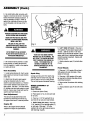
ASSEMBLY
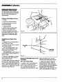
Hitch
Assembly
1. Cut the ties holding the hitch to the
ignitionkey (No hitchon Model 13000).
Secure the hitch (A, Fig. 1) to the rear of
theframe with two 1/2-13 x 1 hex screws,
lock washersand hex nuts(B). Installthe
washersand nuts on the insideof the
frame.
Column
Support
Assembly
1. Removethe three bolts(C, Fig. 2) from
the bottomof the columnsupport.
2. Secure the columnsupportto the
forward end of the frame with bolts
removedin Step 1.
NOTE:Thecolumnsupportshownin
Fig.2 is oneof two different
supports.
Yourun#mayhavea differentstyleof
columnsupport.
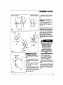
3. Attach the rod end assembly (D, Fig. 2)
on the bottom of the steering columnto
the tie rod (E) as follows:
A. Removethe top cotter pin (F) and
all but one flat washer from the tie rod.
B. Placethe rodend assembly(D) over outdoorpowerequipmentshop,battery
the tie rod.
store or servicestation. OONOTUSEAN
TYPEBATTERY
CHARGER
OR
C. Re-installthe remaining flat washers AUTOMOTIVEELSE
TI-IE
BATTERY
COULO
BEOAMAGEO!
(G). Re-instaUthe cotterpin,
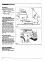
Battery
1. Lift seat supportand disconnect first
the negative(-) andthenthe positive (+)
cablesfrom the battery terminals.
3. Removetwo lock
nutsand washers
from the two "L"
boltsand remove
battery.
4. Fill batterywith
electrolyteto the
level indicatedon
the batterycase.
5. Chargebattery
usinga trickletype
charger. If a trickle
type chargeris not
available,havethe
batteryinitially
chargedat an
'G
D
E
A
\
B
\
\
Fio.1
Fio.2
\
ASSEMBLY
(Cont.)
6. Re-install battery after servicing,with
negative (-) terminal to the left. Re-install
battery hold-down clamps and secure. It
may be necessary to hold "L"-Bolts up
against the underside of frame, so nuts
can be threaded onto the tops of the "L"bolts.
BA'I'rERYELECTROLYTECANCAUSE
SEVEREBURNSAND BLINDNESS.
I
J
H
WEAREYE PROTECTIONAND PROTECTIVECLOTHINGWHENWORKING
NEARA BATTERY.
FAILURETO FOLLOWTHIS
INSTRUCTIONCOULDRESULTIN
PERSONALINJURY OR PROPERTY
DAMAGE.
IN THE EVENTOFAN ACCIDENT,
FLUSHWITH WATERAND CALLA
PHYSICIANIMMEDIATELY.
7. Re-connect first the positive(+) cable
to the positive (+) battery terminal and
then the negative (-) cable to the negative
(-) battery terminal.
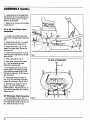
Seat
5. LEFT SIDE OF AXLE:
2. Attach front of seat to seat support
using two shoulder bolts (H), nylon
washer (I) and wave washer (J). Position
nylon washer between wave washer and
seat support. Add one 1-1/4" steel washer
(K) between seat and seat support on each
bolt (H). Secure rear of seat with two flat
washers and hand knobs (L).
Adjustment
The seat can be adjusted forward and
backward by loosening hand knobs (L).
Re-tighten after seat is in desired position.
YOURUNIT HAS BEENSHIPPED
WITHOUT 01LIN THE ENGINE. DO
NOT STARTTHE ENGINEWITHOUT
FIRST CHECKINGTHE ENGINE01L
LEVEL. THE ENGINEWILL BE
SEVERELYDAMAGEDIF IT IS
STARTEDWITHOUT 01LIN THE
CRANKCASE.
Spark
Oil
Refer to the Engine Owner's Manual
supplied for engine oil specifications.
washers(X) on the axleas required. Place
spacerand shims to eliminateplay without
restrictingwheel movement. Securewith
retainingring(V).
7. Attach protector caps (V) to both sides
of axle.
Front
Wheels
1. Place one 1-1/4" washer(Q) and two 13/8" washers(S) ontofront axle. Place
wheel on front axle.
Plug
Unplug spark plug wire from spark plug
and keepwire well away from plug until
you are readyto use your riding mower.
This will help prevent accidentalstarting.
3. Placetwo 1-3/8" washers(U) on axle
as requiredto eliminatefree playwithout
restricting movement.
WHEEL ASSEMBLY
required)
Rear Wheels
5. Attachprotectorcaps(R) to bothsides
of axle.
(If
1. Greaseaxle (Never Seize).
2. Placespacer (Z, Fig.4) onto eachside
of rearaxle.
3. Placetwo 1-1/4" flat washerS (Y) on
each side of rear axleand install wheels.
5. RIGHT SIDE OF AXLE:
Engine
Placetwo 1-
1/4"washers(P) and secondspacer(Z) on
leftaxle. Addtwo or three 1-1/2" shim
Assembly
1. Locate wiring harness (F, Fig. 3) under
seat support and connect to seat interlock
switch (G).
Seat
Fig. 3
Placetwo
1-1/4"washers(P) and secondspacer(Z)
on rightaxle. Placetwo 1-1/2" shim
washers(X) on the rightaxleand secure
with retainingring (W).
4. Secure wheel& washerswith retaining
ring (T).
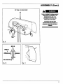
ASSEMBLY
FRONT
REAR WHEELS
(Cont.)
3. Attach s_ouider bolts(Z) to lift plates.
Insert boltfrom the inside. Secure with
nut.
WHEELS
Z
GAGE WHEEL ASSEMBLY
(If
required)
1, Slide a spacer,a gage wheel, and a 1/2
fiat washeronto a 9age wheet axle.
Securewith a cotterpin. Repeat on the
ott_erside,
x
*t
MOWER
Fi0.4
DECK IHSIrALLATtOH
28" Mower
Deck
Installation
The 28" mower deckis shipped assembled
on your riding mower, with the discharge
chuteremoved(this dischargechute
MUST bs _nstalled on the deckbefore
using the mower), Some adjustmentof
the mower deck may alsobe required(See
page 14).
z
%jl
&
TO HELPPREVENTPERSONALINJURY
FROMOBJECTS"THROWN
BYTHE
MOWERDECKBLADE,THE
DISCHARGECHUTEMUST BE
INSTALLEDONTHE OECK.
Fig.5
33"Deck
....
FAILURETO FOLLOWTHIS
INSTRUCTIONCOULDRESULTIN
PERSONALINJURYOR PROPERTY
DAMAGE.
MOWER DEGK LIFT PLATE
ASSEMBLY
(if required]
1. 33" DECKS: PlaceI(ft _(ate(() on
Inside of bracket on mower deck(See
M
FJa.
28" & 36" DECKS: Placelift plate
(I) on inside of bracketon mower deck
(See Fig. 5).
/
/
N
Fi0,6
NOTE:FOR
SHIPPINGPURPOSES
ONLY,A TEMPORARY
SHIELDHAS
BEENII_TALLEDtN THEDISCHARGE
OPENING
ONTHEMOWER_ECK
1. Remove boltsholding temporary shield
in d{sc_arge opening. Removeshield and
discard.
2. Secure withflange screws & nuts at (J,_
2. Loosely attachends of dischargechute
& (K). Nuts should face toward the
(M, Fig. 6) inside discharge opening with
inside of frame.
two 5/16-18 x 3/4 flange screwsand 51163. 33" & 36" DECKS: Placepivot(M)
1B _ange nuts (N). The nuts should be on
intodesired height setf_nghole in lift plate
top.
(1)and secure wit/7washerand spring pin.
See GAGE WHEEL ADJUSTMENT to
determine properheight.
9
ASSEMBLY
(Cont.)
3. Looselyattachtop of dischargechute
with two 5116-18 x 3/4 carriageboltsand
two 5116-18 flange nuts (0). The nuts
shouldbe to the outside.
4. Tightenall four nutsand boltsinstalled
in Steps 2 and 3.
33" & 36" Inch Mower
Installation
Deck
1. Lifttractor up and slide mowerdeck
undertractorwith gage wheelstowardthe
rear.
2. Connect lift rods (D, Fig. 7) to mower
decksand securewith springpins (L).
3. Connect pivot rods(E, Fig.7) to lift
plates (F) on mower deck. Secure with
springpins (X).
4. Connectfront of rodend (U, Fig. 6) to
tractorand securewith clevispin (V) and
springpin (W).
P
(
Fig. 7
5. Removebelt guide (P, Fig. 7).
TOPVIEW--33' MOWERDECK
6. Routemower drivebelt over sheave
(Y). It may be necessaryto rotate
differentialto assemblebelt.
u
7. Re-installbelt guide (P) as farto the
front as possible. Re-tightenbelt guide.
Checkclearancebetweenguide(P) and
bolt headon differential.A 1/8" minimum
gap shouldexist.
8. Install mower bladedrive cable(S,
Figs.8, 9 & 10) from tractor, ontocable
support(0), as shownin Figs.8, 9 & 10.
9. With the mower blade drive lever (F,
page 17, Fig.23) in the disengaged
(DOWN) position. Adjustnuts (R, Fig.10
so all slackhas beentaken up in cable (S).
Tightennuts (R).
36" Discharge
Chute Assembly
1. Securedischargechute (T, Fig. 11)
over dischargeopeningwith two 3/8-16 x
3/4 carriageboltsand 3/8-16 top lock nuts
(N). Installso the nuts are on top.
10
Fig.8
V
ASSEMBLY
(Cont.)
TOPVIEW--36' MOWERDECK
TO HELPPREVENTPERSONALINJURY
FROMOBJECTSTHROWNBYTHE
MOWERDECKBLADE,THE
DISCHARGECHUTEMUST BE
INSTALLEDONTHE DECK.
FAILURETO FOLLOWTHIS
INSTRUCTIONCOULDRESULTIN
PERSONALINJURY ORPROPERTY
DAMAGE.
Cablefrom
Tractor
Fig.9
NUTS(R)
CaLE(S)
N
WASHERS
CABLJESUPPORT(Q_)I
Fig. 10
Fig.11
11
ASSEMBLY
(Cont.)
RIDER PREPARATION
FOR
DIFFERENT
SIZED DECKS
U
28"and 36"decksrequirea differentsetup ofthe ridingmower than the 33" deck.
Set-upfor the twoconfigurationsis
describedbelow.
A
C
Remove Seat
1. Lift seat.
Support
Cover
2. Unscrewand removeshift knob.
3. Removescrews(B, Fig. 12) and
removeshift quadrant.
B
4. Unplugseat switch.
5. Removescrews(U) and pull seat
supportfrom seat supportcover.
6. Removeremaining3 screws(A)
securingseat supportcover. Remove2
screws(C) securinggas tankto seat
supportcover. Removeseat support
cover.
Install
Cable
Mower
Blade
Fig.12
/
Drive
1. Threadnut (D, Fig. 13) downwardon
cablethreads until it stops.
2. Threadnut (H) and washer (I) upward
and off cableassembly.
Front Slot
°
/
J
33"
3. 28" & 36" DECKS ONLY: Insert
cable,nut (H) and washer (I) upward
throughrear slot (E) in frame.
E Rear Slot
281'& 36"
33" DECKS ONLY: Insert cable,nut
(H) and washer (I) upwardthroughfront
slot (F) in frame.
4. Placenut (H) and washer (I) at top of
slot and screwdowntightly,securing
cableassemblyto frame.
5. Connect cable to the mower bladedrive
(PT0) lever (G). Fastencable to the right
sideof PTOlever whenfacing towardfront
of rider. Securewith screw(J) and nut as
shownin Fig. 13. Tightenscrew, but allow
someplay so cable may pivot.
12
D
Fig. 13
Connect (Left
Assembly
Side)
28" & 36" Decks
Link to Lift
Only
1. If swivel(J, Fig. 14) is not attachedto
OUTERlift arm, removehairpinand
washer. Attachswivelto the OUTER lift
arm. Swivelloopshouldface to the
outsde(left), overthe OUTER slot. Place
washer and attachhair pin. Hairpin
shouldbe on the inside(right) of lift arm.
2. Slidelink (K) upward,through the
OUTER slot on theframe. Slidelink
throughswivel(J). Thread nut (L) onto
link. The position of the nut will determine
the heightof the mower when set in
transportposition. See instructionsin the
DECK ADJUSTMENTS, on page 14.
ASSEMBLY
Test
Outer Lift Arm
/28"
J
& 36"
W
/33"
Interlock
(Cont.)
System
Beforeoperatingunit, perform the
interlock system test outlined in the
CONTROLS AND OPERA TION on
page 20.
A
Inner Lift Arm_
Fi0.14
3. To install mower deck, Seethe DECK
INSTALLATION on page 9.
Replace Seat, Seat Support
Cover and Seat Switch
33" Decks
1. Position seatsupportcoverin position
as shown in Fig. 12. Thread 2 screws (C)
into gas tank, but do not tighten. Thread
screws (A) into the sides of seat support
cover. Tighten all hardware.
Only
1. If swivel (V, Fig. 14) is not attachedto
INNER lift arm, remove hair pin and
washer. Attach swivel to the INNERlift
arm. Swivel loop should face to the inside
(right), over the INNER slot. Placewasher
and attachhair pin. Hair pin should be on
the outside (left) of lift arm.
2. Slide link (U) upward, through the
INNER slot on the frame. Slide link
through swivel (V). Thread nut (W) onto
link. The position of nut will determine the
height of the mower when set in transport
postions. See instructions in the DECK
ADJUSTMENTSon page 14.
THE SAFETYINTERLOCKSWITCH
SHOULDSHUT DOWNTHE ENGINE
WITHIN A FEW SECONDSAFTERTHE
OPERATORLEAVESTHE SEAT. IF
THIS SWITCHFAILSTO OPERATE,
HAVETHE MOWERSERVICED
IMMEDIATELYBY AN AUTHORIZED
BOLENS
® DEALER. SEVEREINJURY
COULDRESULTFROM NOT
FOLLOWINGTHIS INSTRUCTION.
2. Positionseatsupporton seatsupport
coveras shownin Fig.12. Secureseat
supportwith screws(U).
3. Plugin seat switch.
4. Positionshift quadrant (Q) as shown.
Securewith screws(B, Fig. 11).
5. Secureshift knobontoend of shift
lever.
6. Lower seat.
13
ASSEMBLY
(Cont.)
33" DECKSHOWN-OTHERSSIMILAR
D
\
Fig. 15
Fig. 16
DECK ADJUSTMENTS
All mower decksshouldbe checkedand
re-adjusted,if necessary,beforeusingthe
ridingmower.
36"decksshouldbe checkedafter
assemblyand installationfor proper
adjustment.
All DecksmTransport
Adjustment
Height
A 1/2" socketwrenchwith an extension
and a universaljoint is recommended for
this adjustment. When mower lift lever
(See page 18, Item I)is in the raised(UP)
position,there shouldbe a gap of no more
than 1/8" betweenshoulderbolts(J, Fig.
16) on the mower deckliftingplates and
frame. If adjustmentis necessary,lift seat
and seat support. Removelift rodfrom
mower deckand push lift rod up through
frameso nuts (D, Fig15) areaccessible.
Turn nuts (D) with the socketwrench, reattachmower deck,and check. Repeatas
necessary.
28" Decks_Mower
Tension Adjustment
Drive
Belt
Check distance (K, Fig. 17), between
center of pivot block and center of pivot.
Normal distanceshouldbe7-1/2" (7-1/4"
for36" Decks). NOTE'AFTER
THEMOWER
HASBEENUSEDFORA WHILE,THEMOWER
DRIVEBELTCANSTRETCH
ANDBEGIN
14
Fig. 17
SLIPPING.MOVEDECKFORWARD
BY
ROTATING
PIVOT(E) TOTHEREARONROOS
(F) TOPROVIDE
ADDEDBELTTENSION.
READJUSTFRONTLINKTOLEVELMOWER.
(SEEPAGE25,MOWERDRIVEBELT
REPLACEMENTFORADOITIONAL
DRIVE
BELTADJUSTMENT
INFORMA
TION).
33" & 36" Decks-Mower
Belt Tension
Adjustment
Drive
Belttensionis controlledby positionof
idler (M, Figs.19 & 21) and pivot rods(F,
Fig. 17). Distance(K, Fig. 17) shouldbe
7-1/2' for 33" decks7-1/4" for 36"decks.
Adjustpositionof idler (M, Figs.19 & 21)
by movingit along the slot. If further
adjustmentis necessary,adjustdistance
(K, Fig. 17) by rotatingpivot(E) to the
rear. Re-adjustfrontcenter linkto level
mower. NOTE'AFTER
THEMOWB_HAS
ASSEMBLY (Cont.)
BEENUSEDFORA WHILE,THEMOWER
DRIVEBELTCANSTRETCH
ANDBEGIN
SLIPPING.MOVEDECKFORWARD
BY
RELOCATING
PIVOT(E)ONPIVOTRODS(F)
TOADDBELTTENSION.RE-ADJUST
FRONT
CENTER
LINKTOLEVELMOWER.
TOP VlEW--2r MOWERDECK
(SEEPAGE25,MOWERDRIVE BELT
REPLACEMENTFORADOITIONAL
DRIVE
BELTADJUSTMENT
INFORMATION).
S
28" & 36" Decks--Mower
Spring Connection
Adjustment
With mower lift lever(See page18, Item I)
in the disengagedposition, adjustcable
(S, Figs.18, 20, & 21) at nuts (R, Fig. 20)
untilall slackin cablehas beentakenup.
WHEN ADJUSTED, SPRING (T)
SHOULD NOT BE UNDER TENSION.
Fig. 18
Cablefrom
Tractor
TOPVIEW--33'MOWERDECK
33" Decks--Mower
Spring
Connection
Adjustment
With mower lift lever (See page 18, Item I)
in the disengaged position, adjustcable
(S, Figs.19 & 21) at nuts (R, Fig.21) so
there is a slight slackin cable. WHEN
ADJUSTED, SPRING (T) SHOULD
NOT BE UNDER TENSION.
MOWER
DECK
LEVELING
Park the riding mower on a hard, level
surface.
Fig. 19
TOPVIEW--36' MOWERDECK
NUTS(_
CaLE(S)
WASHERS
CMLE SUPPORT(Q_) I
Fig.20
Fig.21
Cablefrom
Tractor
15
ASSEMBLY
(Cont.)
Tire Pressure
1. Usean automotive-typetire gaugeto
checkthe air pressurein all four tires.
Fronttires .........from 12 to 15 PSI (82
to 103 kPa) equallyinflated.
Rear tires..........from 8 to 10 PSI (55 to
68 kPa) equallyinflated.
D
DO NOT OVER-INFLATE.
Front
to Rear Leveling
1. Checktire pressureas explainedabove.
2. Place mower lift lever (I, page 18) to
the lower(DOWN) position so deckis in
cuttingposition.
3. Adjustmower height adjustingknob
(G, Fig.23) so the mower bladesare
approximately2-1/2" from the ground.
4. Aligna cuttingbladeso tips point to
the front and rear of the unit. Measure
distancefrom ground to tips of blade. (R,
Fig. 22). Bothtips shouldbethe same
distancefrom the ground. If they are not,
adjustfront rod (A, Fig. 22) as necessary.
Place mower lift leverinto the raised(UP)
positionto adjust. Lowermower againto
recheck level.
R
1
Fig. 22
Side to Side Leveling
1. Aligna cuttingbladeso tips pointfrom
side to side of the unit.
2. Measuredistancefrom groundto tips
of blade. Bothtips shouldbe the same
distancefrom the ground. If theyare not,
remove lift rodfrom mower deckand push
lift rod up throughframe so nuts (D, Fig
22) are accessible.Adjust nuts (D) as
necessary. Re-attachlift rodsand rechecklevel. Repeatas necessary.
Other
Deck
Information
Additional mower deck informationcan be
found in MOWER DECK
MAINTENANCE, beginningon page 25.
16
Fig. 23
A
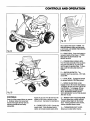
CONTROLS
AND OPERATION
E
way up places the engine in CHOKE. For
best performance, always run the engine
at full throttle. USECHOKEPOSITIONFOR
STARTINGONLY;
Fig. 24
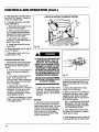
B-- BRAKEPEDAL. Stops the forward or
rearwardmotionof the mower. IT DOES
NOTSTOPTHE ROTATIONOFTHE
MOWERBLADES.
C-- PARKINGBRAKE(BRAKELOCK).
Pushthe brakepedal (B) all the way down
and push brakelock (C, Fig.26) to the
rightto applythe parkingbrake.To disengage, push the brake pedal downand
release.
D D IGNITIONKEYSWlTCH.The
keyswitch has three positions - OFF,RUN,
and START.
E -- DRIVEPEDAL. Engagesthe forward
or rearward motionof the riding mower.
G
F-- MOWER BLADEDRIVELEVER.
Engagesdrive to the mower deck blade(s).
To engage,lift lever and move it to the left
into the detent. To disengage, lift lever,
push it to the right, and slowly release.
NOTE:DISENGAGEMOWERBLADE
DRIVEWHENEVERTHE CUTTINGBLADES
ARENOT IN USE.
Fig. 25
CONTROLS
Know the riding mower before you operate
it. Carefully review this manual and
become thoroughly familiar with the
operatingprocedures and safety
precautions.
Figures 24, 25, 26, 27 & 28 show you the
location of all primary controls on your
riding mower. See below for descriptions.
A-- ENGINESPEEDLEVER. Controlsthe
engine speed. Downdecreasesengine
speed,up increases enginespeed,all the
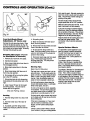
G -- MOWERHEIGHTADJUSTINGKNOB.
This knob allows you to select infinitely
variable cutting heights for the mower
deck. Twisting clockwise raises mower,
counter-clockwise lowers mower.
H --TRANSMISSION SHIFT LEVER.
Allows you to select eitherreverse,
17
CONTROLS
AND OPERATION
(Cont.)
neutral,or one of five forward gears.
(See SPECIFICATIONS on page 6 for
average speeds in some of these
gears). Until you become familiar with
the riding mower, use onlythe lower gears
either 1, 2, or 3. See Fig. 27 for detailed
shifting pattern.
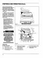
I-- MOWER LIFT LEVER.(Fig. 28) While
in the UP position, the mower deck is in
transport position. In the DOWN position,
the mower deck is in the mowing position.
The Mower Lift Lever should be in the UP
position wheneverthe riding mower is not
actually mowing.
NOTE: THISRIDINGMOWERHAS
INTERLOCK
SWITCHES
A T THEBRAKE,
MOWERCLUTCH,ANDSEAT. THE
UNITWILLNOTSTARTUNLESSTHE
BRAKEPEDAL
IS DEPRESSED
(ORTHE
PARKING
BRAKEISSET),ANDTHE
MOWERBLADEDRIVELEVERISIN THE
DISENGAGED
POSITION.
Fig. 27
VIEW OF SHIFT PATTERN
DECAL
FROM OPERATOR_POSITION
THEENGINE
WILLAUTOMATICALLY
STOPIF THEOPERATOR
LEAVESTHE
SEAT WHENEITHER
THEMOWERBLADE
ISENGAGED
ORTHEBRAKE
PEDALIS
NOTDEPRESSED.
THE SAFETYINTERLOCKSWITCH
SHOULDSHUT DOWNTHE ENGINE
WITHIN A FEW SECONDSAFTERTHE
OPERATORLEAVESTHE SEAT. IF
THIS SWITCH FAILSTO
OPERATE,HAVETHE MOWER
SERVICEDIMMEDIATELYBYAN
AUTHORIZEDBOLENS®DEALER.
SEVEREINJURY COULDRESULT
FROM NOT FOLLOWINGTHIS
INSTRUCTION.
II
III
Fig. 28
OPERATION
Pre-Start
Checklist
[] 1.
ReviewSection 1: SAFETY.
[] 2.
Checkthe engineoil level.
[] 3.
Fillthe fuel tank. (See Filling
Fuel Tank, below.)
18
r-14.
1-15.
a.
Checkthe unitfor any loose or
missing hardware. Tighten or
replaceas necessary.
Inspect the batteryfor:
Proper electrolyte level.
Cleancablesand battery terminals.
Cleanany debrisoff engine
flywheelscreen.
CONTROLS
_7.
AND OPERATION
(Cont.)
Checktire inflation:
Fronttires:from 12 to 15 PSI (82 to
103 kPa) equallyinflated.
Rear tires:from 8 to 10 PSi (55 to
68 kPa) equallyinflated.
DO NOT OVER-INFLATE,
Re-connect spark plug,_ireto
spark plug.
Make sure mowerdischarge
deflectorshieldis securely
fastened to the right-handside of
mowerdeck (28 & 36 inch decks).
O10.
Adjustseat to a comfortable
position. (See page 8, Seat
Adjustment.
[311.
Ct_eckarea to be _o_.
e,_,_
anydebrisfrom this area.
[] 12. Set parkingbrake.
[] 13 Place transmission shift lever (rite
N (Neutral) (Fig. 2_').
Filling
8. Do not completelyflit thefuel tank.
Allowat least 1/4-inch of space at the top
of the tank. This allowsfor fuel expansion.
Fuel Tank
1. Disengagemowerblade drive.
2. Shut offengine
3. Set parking brake.
3. Allow engine to coolfor at least two
minutes before filling fuel tank.
4. Move transmission shift lever into 4th
or 5th gear to allow accessto fuel tank
filler cap.
5. Tilt seat and seat support (P, Fio. 29)
forward and upward.
6. SLOWLY unscrew fuel tank filler cap
(o).
7. Use a good grade of clean,fresh,
unleaded gasoline. SLOWLYpour gas into
tank. Usea funnel if necessary (make sure
that it is clean). Frequentlystop and check
the level of fuel in tank white_illing.
GASOUNEIS HIGHLYFLAMMABLE
AND ITS VAPORSAREEXPLOSIVE,,
OQNOT ADDGASOLINETO THETARK
WHILETHEENGINEIS RUNNING. IF
THE ENGINEHASBEENRUNNING,
ALLOWITTO COOLFOR SEVERAL
MINUTES.
DONOT ALLOWOPENFLAMES,
SPARKS,MATCHES,ORSMOKING
NEARBYWHENREFUELLING.
F|LLTHE GASTANKOUTDOORSIN A
WELL-VENTILATEDAREA. WIPE UP
Ally SPILLSMiD MOVETHE RIDING
MOWERAWAYFROMGASOLINE
FUMES BEFORESTARTINGTHE
ENGINE.
NEVERBRINGA GASOLINECANNEAR
THE BATTERYPOSTS. A SHORT
CIRCUITCAUSEDBY TOUCHINGTHE
POSITIVE(+) POSTANDANY METAL
COULDCAUSEANEXPLOSIONOF
GASOLINEOR BATTERYGASES.
9. Re-instal} fuel tank fillercap and the cap
on the fuel container.
10. Wipe up any spilledgasoline,
11. Tilt seatand seatsupportrearward
and downward.
Starting
1. PerformPre-Start Checklist
_scribed earlier.
2. Set parkingbrake(C, Fig. 26, page17).
The enginewill not startunless the brake
pe_l is down.
3. When startinga cord engine,m_
enginespeed I_v_r (A, Fi_.2_,, pa_e17} all
the way up to theCHOKE position.
Whenstarting a warm engine,set throttle
at 3/4 full position.
4. Move mower blade drivelever (See F,
page 17) art the way (lownto its
disengaged position. (The enginewill not
start if the mower bladedrive is engaged.)
5. Sit in the operator'sseat.
6. Move the transmission
shift lever(See
Fig. 27, page 18) to N (Neutral).
7. Belore starting engine,make sure there
are no childrennearby.
19
CONTROLS
AND OPERATION
8. Place ignitionkey in keyswitch and turn
key to the START position. Releasekey
as soon as the enginestarts.
(Cont.)
POSITIONOFCONTROLSIN TRANSPORTPOSITION
9. To manuallystart engine:(all models
except 13000 [2027])
A. Place ignitionkey in keyswitch and
turn key to the RUN position.
f
B. Slowly pull recoilstarter rope (A,
Fig. 31) outward until you feel some
resistance from engine compression-then rapidly pull rope outward.
C. Allow starterrope to gradually
rewind rope. Do not releaseropeand
allow it to snap back.
D. RepeatSteps9B and 9C untilthe
engine starts.
Fig.30
10. Move enginespeedlever (A, page 17)
to the FAST position.
11. Allow engineto warm up for a few
minutes before you mow.
Interlock
System
Test
1. Before working with the riding mower,
always perform an operational check of
the riding mower's interlocksystem as
follows:
A. Parkthe unit on a level surface so it
does not roll when you releasethe
brake.
B. Sit in operator's seat and start the
engine. (See Starting on the
previous page) Depressbrake pedal
and check to make sure mower blade
drive is disengaged.
C. Releasebrake. Raise yourself
several inches off the seat. The engine
should stop. If it does, go on to the
next step. If it does not, havethe
interlock system adjusted or repaired.
DONOTOPERATE
THEUNIT!
D. Depress brake pedalagain. Re-start
engine. Raise mower blade drive lever
to its engaged position.
IF THE INTERLOCKSYSTEMDOESNOT
FUNCTIONPROPERLY,SHUTTHE
ENGINEOFF,APPLYTHE PARKING
BRAKE,ALLOWTHE ENGINETO COOL,
DISCONNECTTHE SPARKPLUGWIRE
AND PREVENTIT FROMTOUCHING
THE SPARKPLUG,AND REMOVETHE
KEYFROMTHE KEYSWITCH.DO NOT
USETHE RIDING MOWERUNTILTHE
INTERLOCKSYSTEMIS REPAIRED.
FAILURETO FOLLOWTHIS WARNING
COULDRESULTIN PERSONALINJURY
OR PROPERTYDAMAGE.
I
IIII
IIIIII
E. Again,raise yourself severalinches
off the seat. The engineshouldstop. If
it does not, have the interlock system
adjusted or repaired. DONOTOPERATE
THEUNIT!
Mowing
1. After performing the interlock system
test on you ridingmower,you are now
readyto beginactualmowing. Put mower
lift lever (B, Fig.30) up intothe raised
position,and put themower bladedrive
lever (C) down into the disengaged
positionwhile transportingyour riding
mower to the work area.
A
Fig.31
2. Onceyou have arrived at the work area,
releasethe drive pedal and stop the unit.
Make sure the throttle lever is in the FAST
position.
3. Select cutting height(See Testing
height of Cut, next page.)
4. Make sure that no one is in the path of
discharge or close to the mower. Slowly
engagethe mower bladeby moving the
mower blade drive lever (C, Fig. 32) up to
its ENGAGED position.
NOTE:THEMOWERBLADEDRIVECANBE
DISENGAGED
ATANYTIMEBY MOVING
THEMOWERBLADEDRIVELEVER
DOWN
TOITSDISENGAGEO
POSITION.
5. Lower mower lift lever (B, Fig. 32) to
the lowest (DOWN) position, to position
mower deck for cutting.
6. Select the gearyou want by moving the
transmission shift lever(Z, Fig.32) to the
20
CONTROLS
AND OPERATION
(Cont.)
POSITIONOF CONTROLSIN MOWINGPOSITION
P
Fig.32
desiredgear. Do not mow in R (Reverse).
Here are somegeneralgear selection
guidelines:
1st gear: Goingup or down
moderatehills,travellingon slippery
surfaces, highgrass.
2nd/3rd gear: Levelterrainto mild
slopes,normalgrass.
4th gear: Levelterrain,light
mowing.
5th gear: Travelfrom storagesite
to work location.
Reverse: Movingout of storage
site, maneuveringin tightareas.
7. Slowly depressthe drive pedal(E, page
17) to beginmoving.
NOTE:AFTERYOUBEGINMOVING,
YOUCANSHIFTTOANYOFTHE
HIGHERORLOWERGEARS"ONTHE
GO". YOUDONOTHAVETOCOMETO
A COMPLETESTOP--ALLYOUHAVE
TOO0 IS LETUPONTHEORIVEPEOAL
WHENYOUSHIFI_.HOWEVER,
YOU
MUSTCOMETOA COMPLETE
STOP
WHENEVER
YOUSHIFTFROMA
FORWARO
GEARTOREVERSE
OR
FROMREVERSE
TOA FORWARO
GEAR.
Testing Height of Cut
After mowing a small area, it is
recommended thatthe mower be stopped,
the parkingbrakeset, and the height of the
cuttingarea inspected(Make surethere
are no small childrenor inattentive
persons aroundyou when this is done).
The area can be inspectedfrom the
operator'sposition. If you wish to leave
Fig. 33
the operator'sposition, disengagemower
blade drive and stopenginebefore doing
so (See Stopping, on next page).
Twist the mowerheightadjustingknob(D,
Fig.32) or clockwiseto raisethemower
(highercut), counter-clockwise
to lower
the mower(shortercut). A goodcutting
heightto beginwith is 2-1/2".
Generally,if the mower is set too low, the
grasstends to mat and clump. (This can
also happen if the grass is wet. See
Mowing Tips, on the following page.)
If this doeshappen,raisethe mowerabout
1/4"and test the cutagain. Repeatuntila
cleancut isachieved.
If you havea unit equippedwith a 33"
mulching deck, cuttingheight is a very
importantfactor in mulchingperformance.
Set the cuttingheighthighenoughsothat
the deckis not overloaded.Too much
grassin the cutting chamberat one time
limitstheamountof circulationinsidethe
deckand impairsmulchingaction. An
"overloaded"deckwill leavegrassclumps.
Generally,a mulchingdeckthatis setat a
slightlyhighercutting heightwill give
betterperformancethan one thatis settoo
low. (See also Mowing Tips, on the
following page.)
GAGE WHEEL
ADJUSTMENT
The gagewheelsare primarilyan antiscalpdevice. Adjustsothey arejust off
theground. If severalcuttingheightswill
be usedduringa cuttingsession,set the
gagewheelswhilethe mower deckis in
the lowestcuttingpositionthat will be
used.
While mowingextremelyrough, uneven
or hilly terrain, it is best to allow the
mower deckto ridedirectlyon the gage
wheels. In this case, set the gagewheels
so they contactthe groundwhen the
mower deckheight has beenselected.
Rear Gage Wheel
28" Decks
Adjustment,
Removethe nuts securingthe gage
wheels. Placethe gagewheels in the
desiredposition (P, Fig.33) and secure
with nuts. Set both gagewheelsto the
same height.
33"&
36"Decks
Removespring pin and washerand
position swivel(M, Fig.34, following
page) into desiredhole. Replacespring
pin. Set bothgage wheelsto the same
position.
Nter proper cuttingheight has been set,
the mower deck gagewheels should be
adjusted as well. Before doing this, stop
the tractor. (See Stopping, Next
page.)
21
CONTROLS
AND OPERATION
(Cont.)
from weekto week. Alternatemowingthe
lawnfrom northto southandfrom east to
west. Thiswill helppreventmattingand
grainingof the grass.
33"
Forbest results,alwaysmow with the
enginespeedlever in its FAST position.
Makesure the mower deckis level. If the
deckis not level itwill cut unevenly.
Fig.34
Front Anti.Scalp
Wheel
Adjustment,
33" Decks
If you are not usingan optionalbagging
attachment,directthe dischargetowards
the cut portionof the lawn. Thiswill best
dispersethe clippings. (See also Testing
Heightof Cut,on the previouspage.)
Fi0. 35
5. Move transmissionshiftleverout of
the N (Neutral) position.
Keepthe insideof the mowingdeckclean
and free from grass buildup.(See
STORING YOUR RIDING MOWER,
page 31.)
6. Removekeyfrom key-switchand store
it out of the reachof children.
Special
4. Set parkingbrake.
only
Removethe nuts securingwheels. Place
wheel in the desiredposition (Q, Fig. 35)
and securewith nuts removedearlier. Set
bothwheelsto the same height. Normally,
the lowerhole shouldbe used.
Stopping (See pages 17 & 18
for description
of controls)
1. Removeyour foot from drivepedal.
2. Depressbrakepedal.
3. Move mower blade drivelever downto
the disengagedposition.
7. Do not parkthe ridingmower on a
slope. Blockthewheels(place blocks of
wood on both sides Of the wheels) to
prevent it from rolling.
8. Disconnectsparkplug wirefrom spark
plug. Preventspark plug wire from
touchingsparkplug. This will prevent
accidentalstarting.
4. Move enginespeed leverto the slow
position.
Mowing
5. Movetransmissionshift lever out of
the N (Neutral) position.
The besttime to mowyour lawn is in the
earlyafternoon. Thisis usuallywhen the
grass is mostdry. Avoidcuttingthe lawn
when it is wet--wet grasstendsto form
clumps. Also, thesensitivenewlycut
areaswill not be exposed to directsun.
6. Shut engineoff byturning the ignition
keyto the OFF position.
7. Set parking brake byfully depressing
brakepedaland moving brakelock to the
right.
8. Lowermower lift lever to the lowest
(DOWN) position. Thiswill restthe
mowerdeck on the ground.
(Also see Parking, below.)
Parking
1. Parkthe riding mower in a clean,level
spot.
2. Park the mower out of the reachof
children.
3. If possible, park the ridingmower
insidea dry enclosure,afterthe unit has
cooled.
22
Tips
Never mow in R (Reverse).
Forbest performance,alwayskeepthe
mower deckblade(s)sharp. A dull blade
tendsto tear grass,not cut it.
Do not cut the grasstoo short, especially
in hotweather.Thiscankill the grassand
mayallow weedsto gain a foothold. We
recommenda cutting height of 2-1/2".
Forbestresults, adjust mower deckheight
so the bladecutsoff onlythetop third (or
less) of the grass.
If the lawnis overgrown,or if you must
usethe mower on extremely uneven
terrain,use thehighestcuttingheight
setting.
Unlessa specialpatterneffectis desired
(next column), varyyourcuttingpattern
Pattern
Effects
It is possibleto createpatternsin your
lawnby mowing in specificdirections.
You can"train"your lawn to "grain"in a
specificway by mowing in the same
pattern everytime. Some patterns are
listedbelow.
To producea patternof contrasting
stripes. Mow the lawn in parallel strips
that run in oppositedirectionsto each
other. (ForexampleNorth to South and
then Southto North.)
To produce a "diamond" or "checkerboard"
pattern,first mow the lawnin parallel
strips. Then, withina coupleof days,
mowyour lawnagain in parallel stripsbut
at right anglesto thefirst mowing. (For
example:The first mowingis doneeast to
west and/orwest to east. The second
mowingisthen donenorthto .south
and/or southto north.)
MAINTENANCE
TRACTOR
MAINTENANCE
Engine
I
FORSPECIFIC
ENGINE
MAINTENANCE
INSTRUCTIONS,
REFERTOENGINE
OWNER'S
MANUALSUPPLIEO
WITHTHERIOING
MOWER.THEENGINE
OWNER'S
MANUAL
INCLUBESINSTRUCTIONS
FORCHECKING
ENGINE
OILLEVEL,CHANGING
ENGINE
OIL,
INSPECTING
ANOCLEANING
ENGINE
AIR
FILTER,IGNITION
SYSTEMMAINTENANCE,
ANOOTHERIMPORTANT
ENGINE
MAINTENANCE
INFORMATION.
FOR
FURTHER
REPAIRS,
CONTACTYOURLOCAL
BOLENS
_ OEALER.
I
I
n
--.== ,,=,..= L
,.._=
_%
_"'=
./%
!_
__
_
'=""==
r----..._ 3/16.,_1/4.
\
(5-6 mm)
Lubrication
Refer to MaintenanceChart on Page 32 for
lubrication instructions.
Interlock
System
Test
This riding mower is equippedwith an
interlocksystem. Thissystempreventsthe
operatorfrom startingthe engine,if:
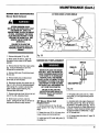
Fig. 36
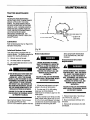
Brake
Adjustment
1.) ...thereis no one in theseat.
2.) ...the brake pedal is not depressed.
3.) ...the mower bladedrivelever is in the
engagedposition.
IF THE INTERLOCKSYSTEM DOESNOT
FUNCTIONPROPERLY,SHUTTHE
ENGINEOFF, APPLYTHE PARKING
BRAKE,ALLOWTHE ENGINETO COOL,
DISCONNECTTHE SPARKPLUGWIRE
AND PREVENTIT FROMTOUCHING
THE SPARKPLUG, AND REMOVETHE
KEYFROMTHE KEYSWITCH.DO NOT
USETHE RIDING MOWERUNTILTHE
INTERLOCKSYSTEM IS REPAIRED.
FAILURETO FOLLOWTHIS WARNING
COULDRESULTIN PERSONALINJURY
OR PROPERTYDAMAGE.
See Interlock System Test on page
20, in the CONTROLS AND
OPERATION section to perform this test.
BEFOREADJUSTINGTHE BRAKE,
SHUTTHE ENGINEOFF, BLOCKTHE
WHEELS,ALLOWTHE ENGINETO
COOL,DISCONNECTTHE SPARKPLUG
WIRE ANDPREVENTIT FROM
TOUCHINGTHE SPARKPLUG,AND
REMOVETHE KEYFROMTHE
KEYSWITCH.
FAILURETO FOLLOWTHIS WARNING
COULDRESULTIN PERSONALINJURY
OR PROPERTYDAMAGE.
1. Lift seat and seat support up to gain
access to the side of transmission.
2. Turn hex nuts (C, Fig. 36) holding
brake lever to left-hand side of
transmission to remove any play from the
brake system.
3. Havean assistant push firmly on brake
pedal. Adjust until a gap of 3/16" (5 mm)
to 1/4" (6 mrn) exists between front edge
of brake lever (B) and forward edge of slot
in frame the brake lever goes down
through.
NOTE."
DONOTOVER-TIGHTEN
NUTS
(C)ORTHEBRAKEWILLORAG
ANO
OVERHEAT
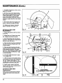
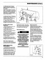
Transmission
Replacement
Drive
Belt
BEFOREREMOVINGTHE TRANSMISSION DRIVEBELT, SHUTTHE ENGINE
OFF, BLOCKTHE RIDING MOWER'S
WHEELS,ALLOWTHE ENGINETO
COOL,DISCONNECTTHE SPARKPLUG
WIREAND PREVENTIT FROM
TOUCHINGTHE SPARKPLUG,AND
REMOVETHE KEYFROMTHE
KEYSWITCH.
FAILURETO FOLLOWTHIS WARNING
COULDRESULTIN PERSONALINJURY
OR PROPERTYDAMAGE.
1. Remove mower deck. See Mower
Deck Removal, page 25.
2. Move transmission shift lever to N
(Neutral).
3. Remove old transmission drive belt.
and discard.
23
MAINTENANCE
(Cont.)
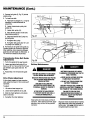
4. Removebelt guide (C, Fig. 37) behind
enginepulley.
5. To installnew belt:
A. Placebelt intosheave(F). It may be
necessaryto rotatedifferentialto
assemble.
B. Loosentransmissionpulleybelt
guides (G).
\
C. Loosenidler pulley (H).
D. Placeforward portion of belt onto
transmissionpulley (I).
E. Placebelt betweenidler pulley (H)
and belt guide.
Fig.37
D
/
F. Re-tightenidler pulley.
G. Re-tightenbelt guides (G) 1/8" (.32
cm) awayfrom sheave(F).
6. Re-installand re-tightenbelt guide(C).
Positionguideas far forward as possible.
After assembly,checkclearancebetween
guide (C) and bolt headson differential. A
1/8" minimumclearanceshouldexist.
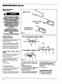
Transmission
Adjustments
Drive
A
Belt Guide
1. Pushdrive pedal all the way forward.
2. Loosenand adjust beltguide (C) so
there is a 1/8" (3.1 mm) to 3/16" (4.7 mm)
gap betweenupperguide and belt. Retighten.
Fig.38
Battery
/
Maintenance
3. RepeatStep 2 for forward belt guide
(G).
Drive Chain
BATTERYELECTROLYTE
CANCAUSE
SEVEREBURNSANDBLINDNESS.
Adjustment
If drivechainappearsto haveexcessive
slack,adjustto prevent it from coming off
sprockets.
To adjust:
1. Liftseat and seat supportup.
2. LoosenchaintightenerLA,Fig.38).
3. Slidethe chaintighteneruntil excess
slackis removed.
WEAREYEPROTECTIONAND PROTECTIVE CLOTHINGWHENWORKING
NEARA BATTERY.
FAILURETO FOLLOWTHIS
INSTRUCTIONCOULDRESULTIN
PERSONALINJURY OR PROPERTY
DAMAGE.
IN THE EVENTOFAN ACCIDENT,
FLUSHWITH WATERAND CALLA
PHYSICIANIMMEDIATELY.
4. Re-tighten the chaintightener.
Keepbattery terminals cleanand free of
corrosion. After cleaningterminals, apply
petroleum jelly on them to help prevent
corrosion.
24
BATTERIESCANGIVE,OFFHIGHLY
FLAMMABLEHYDROGENGASTHAT IS
EASILYIGNITED.
• NEVERALLOWA SPARKOR OPEN
FLAME NEARTHE BATTERY.
• DO NOTLAYTOOLSACROSSTHE
BATTERYTERMINALS.
• DO NOTTOUCHATOOL FROMTHE
POSITIVE(+) BATTERYTERMINALTO
THE FRAMEOFTHE RIDINGMOWER.
FAILURETO FOLLOWTHIS
INSTRUCTIONCOULDRESULTIN
PERSONALINJURY OR PROPERTY
DAMAGE.
Regularly checkelectrolytelevel in battery.
Keepelectrolyte within level indicatedon
batterycase. Addonly distilledwaterto
bringelectrolyteto properlevel.
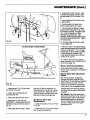
MAINTENANCE
MOWER
Mower
DECK
Deck
MAINTENANCE
(Cont.)
33" DECKSHOWN--OTHERSSIMILAR
Removal
BEFOREREMOVINGOR REINSTALLINGTHE MOWER DECK,SHUT
THE ENGINEOFF, APPLYTHE
PARKINGBRAKE,ALLOWTHE ENGINE
TO COOL,DISCONNECTTHE SPARK
PLUG WIRE ANDPREVENTIT FROM
TOUCHINGTHE SPARKPLUG, AND
REMOVETHE KEYFROM THE
KEYSWITCH.
FAILURETO FOLLOWTHIS
INSTRUCTIONCOULDRESULTIN
PERSONALINJURY ORPROPERTY
DAMAGE.
1. Removebelt guide (P, Fig. 39)
2. Move mower lift lever (I, page 16)
downward to set mower in the lowest
position.
3. Removethe belt from the engine pulley
(B). It may be necessary to turn the
differential to remove belt.
4. Removehitchpins(C) anddisconnect
lift rods(D).
5. Remove hitch pins and disconnect
pivot rods (F) from lift plate.
6. Disconnectmower drivecable cable (S,
Figs. 41,42 & 43 on the following pages)
from spring (H). Loosen nuts securing
cableto cable support (See Fig. 40).
Removecable from deck.
7. Remove clevis pin from the front of rod
end (E, Fig. 39), releasing mower.
8. Slide mower out from under the
tractor. Swing the lift rods (D) forward or
backward to allow for easy removal.
Fig.39
MOWER
BELT REPLACEMENT
NUTS(It)
BEFOREREPLACINGTHE MOWER
DECKBELT,SHUTTHE ENGINEOFF,
MOVETHE MOWERBLADECLUTCH
LEVERDOWNTO ITS DISENGAGED
POSITION,APPLYTHE PARKING
BRAKE,ALLOWTHE ENGINETO COOL,
DISCONNECTTHE SPARKPLUGWIRE
ANDPREVENTIT FROMTOUCHING
THE SPARKPLUG,ANDREMOVETHE
KEYFROMTHE KEYSWITCH.
FAILURETO FOLLOWTHIS
INSTRUCTIONCOULDRESULTIN
PERSONALINJURYOR PROPERTY
DAMAGE.
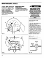
28" Mower Drive Belt
Replacement
1. Remove belt guide (P, Fig. 39) and
loosenguides (Y & H, Fig.41 on following
page).
2. Rotate idler arm (B, Fig. 41) away from
mower sheave and remove old belt.
3. Install new belt (Z) under belt guide (Y)
on pulley (X),
WASHERS
CULE SUPPORT(Q_) I
Fig.40
4. Re-tighten idler pulley bolt (T). Make
sure guide(Y) is in approximate position
as shown.
5. Assemble belt ontoenginesheaveand
slidebelt guide (P, Fig. 39) as far forward
as possible. Re-tighten guide (P). NOTE:
It may be necessary to rotate differential to
assemble. Check clearance between guide
(P) and bolt heads on differential. A gap
of 1/8" should exist.
6. Lift mower blade drive lever (F, page 15)
to engagedrive.
25
MAINTENANCE
(Cont.)
7. Re-tighten beltguide(H) 1/16' (.15 cm)
awayfrom drivebelt.
H
8. With the mower in the highestsetting,
checkclearancebetweenbelt at point (AA).
If there is not at least a 1' (2.5 cm) gap,
move mower ahead by adjusting pivot
location on lift arms (E, Fig. 45). It may be
necessaryto adjust rod (A, Fig. 45) to level
mower.
9. With mowerbladedriveengaged,belt
guide (Y) should not contactdrive belt.
10. Checkto see if mower is leveland
adjustif necessary(See page 16).
33" Mower Drive
Replacement
Belt
Fig. 41
Y
1. Loosen belt guides (A & B Fig. 42 and
(P, Fig. 45).
2. Rotate idler arm (C) away from pulley
(R). Replace belt (Z) with new belt.
3. Route belt betweenidler (Q) and belt
guide (A). Place guide(A) in approximate
position shownand secure.
4. Placenew belt into groove of stationary
idler (E) and secure belt guide(B) in rear
of slot as shown.
5. Placenew belt into groove of engine
pulley and assemblebelt guide (P, Fig.45)
as far forward as possible. Re-tighten
guide (P). Check clearance between guide
(P) and bolt heads on differential. A gap
of 1/8" should exist
S
A
Fig.42
6. Lift mower bladedrive lever (F, page
17) to engagedrive.
f
\
7. With the mower in the highest setting,
checkclearance between belt at point (AA,
Fig. 44) If there is not at least a 1" (2.5
cm) gap, move mower ahead by adjusting
pivot location on lift arms (E Fig. 45).
/
\
I
8. Checkto see if mower is level and
adjust if necessary(See MOWER DECK
LEVELING, page 16).
\ /
33" Mower Blade Belt
Replacement
Mowerdrive belt must first be removed
(as describedearlier) beforedoingthis
repair.
BLADESSHOULD
BEPERPENDICULAR
TO EACHOTHER
/
Fig. 43
26
MAINTENANCE
J
(Cont.)
3. Replacebelt (Z) with new belt. Place
new belt aroundpulleys,betweenidlers
and beltguides(J & S) as shownin Fig.
44.
S
4, Secure belt guide(S) and idler in rear
of slot as shown.
6. Positionguide (J) throughholein
bottomof plateand securein place.
7. Placenewbelt intogrooveof engine
pulley and slidebelt guide(P, Fig.45) as
far forward as possible. Re-tightenguide
(P). It may be necessaryto rotate
differentialto assemblebelt. After
assembly,checkclearancebetweenguide
(P) and bolt headsof differential.A gap of
1/8"shouldexist.
C
Fig. 44
8. Lift mowerblade drivelever (F, page
17) to engagedrive.
33" DECKSHOWN-OTHERSSIMILAR
9. With the mower in the highestsetting,
checkclearancebetweenbelt at point (AA)
If there is not at leasta 1"(2.5 cm) gap,
relocateidler (X) as far ahead as possible.
If moreadjustmentis needed,move
moweraheadbyadjustingpivot location
on lift arms (E, Fig. 45).
10. Checktosee if mower is level and
adjustif necessary(See MOWER DECK
LEVELING, page 16),
Mower
\
pivot arm (G) back in position so it is
applying pressure on pulley (W). Secure
mounting bolts (K). Make sure there is
clearance between the right-hand mower
blade and the deck on the right side.
3. Slide pulley (W) toward the center.
4. Replacebelt (L) with new belt.
IMPORTANT._--cutting blades MUSTbe
perpendicular to each other as shown in
Fig. 43.
5. Slide pulley(W) to the right. Rotate
Drive
Belt Adjustment
Start the riding mower. Engageand
disengagethe mower blade drivelever
(Item F, page 17) while having an assistant
watch the mower drive belt. The belt
should not move when the mower blade
clutch lever is in the disengaged position.
Fig.45
2. Loosenfour mountingbolts(K)
securingpulley (W).
Re-installation
Follow instructions startingon page 9,
Mower Deck Installation to re-install the
mower deck.
Mower
Check
1. Loosen screw (F, Fig. 42) and rotate
arm (G) 90° to the rear.
Deck
36" Mower Drive
Replacement
Belt
1. Loosenbelt guides (J & S, Fig.44 and
P, Fig. 45).
If the belt does move when you perform
this check,shut the engine off and adjust
as follows:
28" Decks
Adjustthe mower ddve
cableend (S, Fig.42 and S, Fig. 48 on the
followingpage)or move mower backby
adjustingpivotlocationon lift arms (E,
Fig. 45). Repeat.thistest until belt does
not move. Checkmower levelingafter
adjustingpivot(E).
2. Rotateidlerarm(B, Fig.44) andbrake
arm(C),and removebelt(Z).
27
MAINTENANCE
(Cont.)
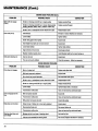
33" & 36" Decks Adjustthe mower
drivecableend (S, Figs.42 & 44 and S,
Fig.48 on thefollowing page) or relocate
theadjustablepulley(B, Fig. 42 or X, Fig.
44) within its slot on the idler support
bracket. If further adjustmentis
necessary,move mower aheadby
adjustingpivot locationon lift arms (E,
Fig.45). Repeatthis test until belt does
not move. Checkmower levelingafter
adjustingpivots (E).
MOWER DECK BRAKE
ADJUSTMENTS
If the mower deck pulleys do not stop
rotatingwithin 5 seconds after placingthe
mowerblade drivelever(F, page 17) into
the disengaged(DOWN) position, adjust
as follows:
BEFOREADJUSTINGTHE MOWER
DECKBLADEBRAKE,SHUTTHE
ENGINEOFF,APPLYTHE PARKING
BRAKE,ALLOWTHE ENGINETO COOL,
DISCONNECTTHE SPARKPLUG WIRE
AND PREVENTIT FROMTOUCHING
THE SPARKPLUG, ANDREMOVETHE
KEYFROMTHE KEYSWITCH.
FAILURETO FOLLOWTHIS
INSTRUCTIONCOULDRESULTIN
PERSONALINJURY OR PROPERTY
DAMAGE.
28" Mower
Adjustment
Deck
Brake
1. Move mower bladedrive leverto the
disengaged(DOWN) position.
2. Adjustcableand spring(K, Figs.46 &
48) at nuts (R, Figs.46 & 48) until all
slackin spring(K, Fig. 46) has beentaken
up. WHEN ADJUSTED, SPRING (K)
SHOULD NOT BE UNDER TENSION
3. If brakepad (A, Fig. 46) is not centered
in pulley(B), Adjustidlerarm pivot(D) as
necessary,by re-locatingwashersat pivot.
4. If bladestill does not stop within5
secondsafter the mower drivehas been
disengaged,replacebrake pad (A).
Fig.46
33" Mower Deck Brake
Adjustment
1. Move mower bladedrivelever to the
disengaged(DOWN) position.
NUTS(_
cuue_ (s)
t._ __
WASHERS
T
Fig.47
28
CABLESUPPORT(Q_) i
Fi0.48
\\\\\_\\\\\\\\\_
MAINTENANCE
2. If brakepad (A, Fig. 47) doesnot
squarelycontactbothtop and bottom
surfacesof pulley (B), re-positionpulley
(B) as follows:
(Cont.)
B
Pulley(B) hasone washeron top and on
bottom. To raise pulleyup, removescrew
(C), placebothwasherson bottomand reinstallscrew(C). To drop pulley down,
removescrew (C), place bothwasherson
top and re-installscrew(C).
3. Adjust cable (S, Figs. 48 & 49) at nuts
(R, Fig.47 & 48) so there is a slight slack
in spring(T, Fig. 47). WHEN
ADJUSTED, SPR/NG (T) SHOULD
NOT BE UNDER TENSION
4. If bladestilldoes not stop within 5
secondsafter the mower drivehas been
disengaged,replacebrakepad (A, Fig.47).
36" Mower
Adjustment
Deck
Brake
Fig.49
1. Move mower blade drive lever to the
disengaged(DOWN) position.
adjustingbarrel to tractor. Secure cable
end to the right-hand side of mower blade
drive lever (M) with screw and nut (P &
0). Re-attach cable to mower deck.
2. Adjustbrakepad (A, Fig. 49) so it
squarelycontactspulley (B).
Blade
Maintenance
3. Adjustnut (E, Fig.49) until the leg on
brakearm (C) contactsbelt.
3. Adjustcable(S, Figs.48 & 49) at nuts
(R, Fig. 48) sothere isa slightslackin
spring(T, Fig.44). WHEN ADJUSTED,
SPR/NG (T) SHOULD NOT BE
UNDER TENS/ON
4. If blade still does not stop within 5
seconds afterthe mower drive has been
disengaged, replace brake pad (A, Fig. 49).
Other
Deck
Adjustments
Information about otherdeck adjustments
can be found in DECK ADJUSTMENT,.
MOWER DRIVE
REPLACEMENT
CABLE
WHENEVERYOU INSPECTORWORK
ONTHE MOWERBLADE(S),
DISCONNECTTHE MOWERBLADE
DRIVE, SHUTTHE ENGINEOFF, BLOCK
THE RIDING MOWER'SWHEELS,
ALLOWTHE ENGINETO COOL,
DISCONNECTTHE SPARKPLUGWIRE
AND PREVENTIT FROMTOUCHING
THE SPARKPLUG,ANDREMOVETHE
KEYFROMTHE KEYSWITCH.
Blade
Inspection
Periodicallyexamineends of mower
blade(s) and area between turned-up and
flat portions on the top of blade.
When mowinggrassin dry or sandy
conditions,abrasiveparticleswear away
the metalconnectingtheseportions of the
blade.(A, Fig. 51.on thefollowingpage)
If a separationstartsformingin the blade
as shownin (B, Fig. 51), you must replace
the blade.
If this wear is allowedto continue,the
separation will enlargeand eventually
allow a portion of the blade to break off.
For best results, always keep blade(s)
sharp. A sharp blade will cleanly cut
grass. A dull blade tends to tear it. See
next pagefor blade sharpening
information.
FAILURETO FOLLOWTHIS
INSTRUCTIONCOULDRESULTIN
PERSONALINJURYOR PROPERTY
DAMAGE.
1. Unhook cable from mower deck and
remove screw and nut (P & O, Fig. 50)
securing cable to mower blade drive lever.
2. Loosen nuts (Q) securing cable
adjusting barrel to tractor. Remove cable.
3. Route new cable up into tractor. 28"
and 36" deck cablesare routed through
front hole (T) 33" deck cable is routed
through back hole (U). Secure cable
Fig. 50
29
MAINTENANCE
Mower Deck
Replacement
(Cont.)
Blade
NEW BLADE
,__
BEFOREREPLACINGTHE MOWER
BLADE(S),DISCONNECTTHE MOWER
BLADEDRIVE, SHUTTHE ENGINEOFF,
CHOCKTHE RIDING MOWER'S
WHEELS,ALLOWTHE ENGINETO
COOL,DISCONNECTTHE SPARKPLUG
WIRE AND PREVENTIT FROM
TOUCHINGTHE SPARKPLUG, AND
REMOVETHE KEYFROMTHE
KEYSWITCH.
FAILURETO FOLLOWTHIS
INSTRUCTIONCOULDRESULTIN
PERSONALINJURY OR PROPERTY
DAMAGE.
BLADE
REMOVAL
28" Blade
EARLY BLADE
WEAR
BLADE
WEAR
DANGEROUS
Fig. 51
28" (except Models 13055 & 13057)
Removal
1. Wrap heavy rags around blade (or wear
heavy leather gloves). Hold blade to
prevent it from turning.
2. Before removing blade, note position:
the raised corners of the blade point up.
33"
A
B
3. Removetwo screws (A, Fig. 52) and
lock washers (B) securing plate (C), and
blade (D) to the spindle assembly (E).
36"(and
Models
13068
13055,
13057,
13067
Models
13055
& 13057)
&
1. Wrap heavy rags around blade (or wear
heavy leather gloves). Hold blade to
prevent it from turning.
2. Removeblade bolt (F, Fig. 52), spring
washer (G), and spindle washer (I)
securing blade (H) to bottom of blade
adapter (J).
Fig.52
F
G
3. Remove blade.
3. Loosen center bolt (K). Removetwo
outer bolts and nuts (L). Removecenter
bolt (K).
33" Blade
36" Blade
Removal
Removal
3. Removebladebolt (F, Fig.52), spring
washer(G), and spindlewasher(I)
securingblade(H) to bottomof blade
adapter(J).
1. Wrap heavy rags around blade (or wear
heavy leather gloves). Hold blade to
prevent it from turning.
1. Wrap heavy ragsaroundblade(or wear
heavy leathergloves). Hold blade to
preventit from turning.
4. Removeblade.
2. Before removing blade, note position:
the raised corners of the blade point up.
2. Beforeremovingblade, noteposition:
the raisedcornersof the bladepoint up.
28" Blade
3O
BLADE
INSTALLATION
Installation
1. Re-p0siti0nblade in place.
MAINTENANCE
2. Re-position plate (C) on bottom of
blade (D). Secure blade and plate with
two new blade screws (A) and new lock
washers (B) to bottom of spindle
assembly (E). Torque screws (A) 25 -30
foot-pounds.
Models
13068
13055,
13057,
13067
&
STORING
MOWER
YOUR RIDING
When storingtheriding mowerfor more
than 30 days:
2. Install two newouter bolts and nuts
(L).
3. Install newcenter bolt (K).
4. Torque bolts (L & K) to 30 footpounds.
5. Make sure the blades are 90° from
each other (See Fig. 43, page 26).
36" Blade Installation
1. Re-position blade in blade adapter (J).
2. Secure with newblade bolt (F), spring
washer (G) and spindle washer (I).
Torque blade bolt (F) from 50 to 70 footpounds.
2. Afterengine hascooled,storeunitin a
dry, protected place.
5. Re-installspark plug. Leavespark plug
wire disconnected.
6. Fullychargebatteryoncea month
duringstorageusing onlya trickle charger
(not an automotive-typecharger,which
could ruin the battery). Thiswill ensure
peak battery power.
7. Cleanundersideof the mowerdeck.
Usea hose,a wire brushor a scraperto
removeanygrassbuildup. (Heavygrass
buildupcanseriouslyeffectthe
performanceof any mowingdeck,
especiallythe 33"mulchingdeck.) To
cleandeck,removeit, usethe optional
Model 6957 storagestand(see page 6),
availablefrom your localBolens dealer,
or set thefront ofyour uniton jackstands.
Mower Deck Blade Re.
sharpening
and Balancing
The deck blade(s) can be sharpenedwith a
file or a grinder. A localsharpening
service can also sharpen them.
To sharpen:
1. Remove equal amounts of metal from
both ends of bladesalong cutting edges.
Sharpen cutting edgesat a 25-30 ° angle.
2. Check balance of blade(s) by inserting
a nail or screwdriver through center hole.
Hold nail level with ground so blade can
rotate on it. Grind or file off heavierend,
as required, to balance blade.
An unbalanced blade will cause vibration
and undue wear on component parts.
11. Blockall four wheels. (Placewooden
blockson bothsidesof wheels.) This
helps preventany accidentalmovement.
1. Move unitoutsideand runengineuntil
it stopsfrom lackof fuel.
3. Remove,clean,and re-gapsparkplug.
1. Re-position blade on bottom of spindle. See Engine Owner's Manual supplied
2. Secure with newblade bolt (F), spring with theunit, for thecorrectgap.
washer (G) and spindle washer (I).
4. Pourone ounceof engineoil through
Torque blade bolt (F) from 35 footsparkplug holeinto engine. Placea clean
pounds.
rag overspark plug holeand crankengine
severalrevolutionsto distributeoil on
cylinderwalls.
33" Blade Installation
1. Re-position blade in place.
(Cont.)
JACKSTANDSMUST BEUSEDWITH
EXTREMECAUTION. ALWAYSSET
THE PARKINGBRAKEAND SECURELY
BLOCKTHE REARWHEELSWHENEVER
JACKSTANDSARE USED.
FAILURETO FOLLOWTHIS
INSTRUCTIONCOULDRESULTIN
PERSONALINJURYOR PROPERTY
DAMAGE.
ELECTROLYTE
CANLEAKOUT OFTHE
BATTERYVENTTUBEIF THE MOWER
IS TIPPEDUP ON END ORON ITS
SIDE.
REMOVETHE BATrERYBEFORE
TIPPINGTHE MOWERON ITS END OR
ONITS SIDE.
DRAIN FUELTANK BFORETIPPING
THE MOWERON ITS END OR ON ITS
SIDE.
GASOLINEIS HIGHLYFLAMMABLE
AND ITS VAPORSARE EXPLOSIVE.
DO NOTADDGASOLINETOTHE TANK
WHILETHE ENGINEIS RUNNING. IF
THE ENGINEHAS BEENRUNNING,
ALLOWIT TO COOLFORSEVERAL
MINUTES.
DO NOTALLOWOPENFLAMES,
SPARKS,MATCHES,ORSMOKING
NEARBYWHENWORKINGWITH
GASOLINE.
DRAINTHE FUELTANK OUTDOORSIN
A WELL-VENTILATED
AREA. WIPE UP
ANY SPILLSBEFORESTORINGTHE
UNIT.
NEVERBRINGA GASOLINECANNEAR
THE BATTERYPOSTS. A SHORT
CIRCUITCAUSEDBYTOUCHINGTHE
POSITIVE(+) POSTAND ANY METAL
COULDCAUSEAN EXPLOSIONOF
GASOLINEOR BATTERYGASES.
FAILURETO FOLLOWTHIS
INSTRUCTIONCOULDRESULTIN
PERSONALINJURY ORPROPERTY
DAMAGE.
8. Thoroughlyexamineentireunit for
loose hardware or any damagedor worn
parts. Replaceor repair as needed.
9. Sandand re-paint any rusted areas.
10. Cover yourunitwith a breathable
cover.
31
MAINTENANCE
(Cont.)
Maintenace Chart
BeforeEach
Use
Checkfor looseor
missingfasteners
v'
Checkengineoil level
i,,
Cleanmower deck
After Each
Use
Every25
Hours
Every40
Hours
Every50
Hours
Monthly
Each
Season
v'
Changeengineoil
i,,'
Cleanair cleaner
element
i/
Greaserearaxle
bearingsand front
spindle
vs
Checkmower blade(s)
for balance,
straightness,&
sharpness. Serviceif
necessary
v'
Check, clean & re-gap
sparkplug
Check chaintension.
Adjustif necessary
11
Lightlyoil steeringpivot
linkand rod, brake and
clutchpivot brackets(4)
and idler pivots
v'
Greasefrontwheel
bearings
v'
Troubleshooting
Chart
Before performingand of the correctionsIn this TroubleshootingChart, refer to the appropriateinformationcontainedin this
manual for the correctsafety precautionsand operatingor maintenance procedures.
ENGINEPROBLEMS
PROBLEM
Enginedoesnotstart
32
POSSIBLECAUSE
CORRECTION
Nofuelintank(8HPenginesmaystillhavea small
amountintankandstillnotstart)
Checkfuellevel.Addifnecessary
Blown15 ampfuse(in wiringharness
beneath
seat)
Replace
fuse
Sparkplugwirenotconnected
Connectsparkplugwire
Throttlenotin CHOKEposition
Movethrottleto CHOKEposition
MAINTENANCE
(Cont.)
ENGINEPROBLEMS(Cont.)
PROBLEM
Enginedoesnotstart
(Cont.)
Enginerunspoorly
Engineoverheats
POSSIBLECAUSE
CORRECTION
Interlock
switchinactivated,
parking
brakenotset
and/ormowerbladedriveactivated
Operator
mustbeontheseat,thebrakepedalmustbe
depressed,
andthemowerbladedrive mustbe
desengaged
ortheinterlock
systemwillprevent
engine
from starting
Batterydischarged
ordead.Poorbatterylead
connection
Charge/replace
battery.Check,
cleanandtighten
batteryleadsas necessary
Loose,brokenor corroded
interlock,
ignitionor starter
wires
Findand repair
Badsparkplug
Cleanor replaceandre-gapas necessary
Fueltankventplugged
Clearventinfueltankcap
Malfunctioning
startermotor
Haveunitserviced
byauthorized
dealer
Malfunctioning
engine
Haveunitserviced
byauthorized
dealer
Waterinfuel. Stalefuel
Drainfueltank. Re-fillwithfreshfuel.
Malfunctioning
startersolenoid
Replace
solenoid
Badsparkplug
Cleanor replace
andre-gapas necessary
Clogged
aircleaner
Cleanor replaceasnecessary
Throttleoutofadjustment
Referto engineowner'smanual
Waterinfuel. Stalefuel
Drainfuel tank. Re-fillwithfreshfuel.
Carburetor
outof adjustment
Referto engineowner'smanual
Enginelugsdown(overloaded)
Raisecuttingheight
Loosesparkplug
Tightensparkplug
Lowoillevel
Addoilas necessary
Engiineover-filled
withoil
Removeoilas necessary
Engineairscreenand/orcoolingfinsclogged
with
debris
Cleandebrisfrom engine
Carburetor
outofadjustment
Seeengineowner'smanual
MOWERDECKPROBLEMS
PROBLEM
Bladewillnotengage
POSSIBLECAUSE
CORRECTION
Mowerbladedrivenotactivated
Liftmowerbladedriveleverintoengagedposition
Loosebelt(s)
Tightenbelt(s)
Wornor brokenbelt
Replace
belt
Missingor looseidlerpulley
Replace/tighten
Brakeridingagainstdeckpulley
Adjustbrake
33
MAINTENANCE
(Cont.)
MOWERDECKPROBLEMS(Cont.)
PROBLEM
Bladewillnotengage
(Cont.)
Deckcutspoorly
Deckgivesslopingcut
POSSIBLECAUSE
CORRECTION
Brokenor missingwoodruffkeyin enginepulley
Replace
woodruffkey
Brokenor missingwoodruffkeyin mowerbladespindle
shaft(s)(Models13000,13001,13002& 13004only)
Replace
woodruffkey(s)
Broken,
wornor maladjusted
mowerbladedrivecable
Replace/adjust
cable
Dullblade(s)
Sharpenor replaceblade(s)asnecessary
Loosebelt(s)
Tightenbelt(s)
Brakeridingagainstdeckpulley
Adjustbrake
Deckheightimproperly
setordecknotlevel
Adjustdeck
Loosebladebolt(s)
Tightenbladebolt(s)
Gagewheelssetincorrectly
Adjustgagewheels
Blade(s)installed
upside-down
Installblade(s)withbentcornersfacingup
Deckisnotlevel
Adjustdeck
Tiresarenotevenlyinflated
Checktire pressure.Adjustas necessary
RIDINGMOWERPROBLEMS
PROBLEM
Drivedoesnotengage
Driveisengagedallthe
time
Brakedoesnotfunction
Steeringwheeldoesnot
turnwheels
34
POSSIBLECAUSE
CORRECTION
Wornor brokenbelt
Replace
andadjustbelt
Beltbrakeimproperly
adjusted
Adjustbrake
Drivechainhasjumpedsprocket
Re-install
chainandadjust
Broken,wornor maladjusted
mowerbladedrivecable
Replace/adjust
cable
Brokenor missingwoodruffkeyinenginepulley
Replace
woodruffkey
Loosebelt(s)
Tighten/replace
beltas necessary
Transmission
malfunction
Haveunitserviced
byauthorized
dealer.
Beltimproperly
adjusted
Adjustbelt
Transmission
malfunction
Haveunitserviced
byauthorized
dealer
Beltguidesimproperly
adjusted
Adjustbeltguides
Swivelat rearofbrakerodis improperly
adjusted
Adjustswivel
Disconnected
brakerod
Re-connect
brakerod
Transmission
malfunction
Haveunitserviced
byauthorized
dealer
Missingrollpin from baseofsteeringwheel
Re-install
rollpin
Linkarmnotconnected
tosteeringshaft
Re-connect.
Replace
hardware
if necessary
MAINTENANCE
(Cont.)
RIDINGMOWERPROBLEMS(Cont.)
PROBLEM
Steeringwheeldoesnot
turnwheels(Cont,)
Steeringisroughor loose
POSSIBLECAUSE
CORRECTION
link armnotconnected
to spindle
arm
Re-connect.
Replace
hardware
if necessary
Tierodnotconnected
Re-connect.
Replace
hardware
if necessary
Fronttiresunder-inflated
Inflatetiresto correctpressure(Seepg.16)
Wornsteeringbearings
attopand/orbottomofsteering Replace
bearings
shaft
Unitvibratesor is
excessively
noisy
Unitspullsto oneside
whendrivenonlevel
ground
Looseorwornsteering
parts
suchasfront
wheel
spindles,
front
wheelbushings,
axle
pivot
bolt,
front
axle
assembly,
tie
rodorsteering
shaft
connections
Replace
wornparts/tighten
looseconnections
Looseengine
mounting
bolts
Tightenhardware
Looseengine
pulley
Tightenpulleyhardware
Mowerdeckblades
outofbalance
and/or
loose.
Balance
and/ortightenblades
Wornmowerblade
spindle
bearings
Replace
bearings
Onefront
tire
isunderinflated
Inflatefronttiresevenly(Seepg.16)
BLACK
,
FUSE
WIRING
DIAGRAM
15A
LL = __.._
BLUE/BLACK
REDHELLOW
BRAKE
SWITCH
(OFF)
MOWERDRIVE
SWITCH
OF F
RUN
REAR VIEW OF IGNITION
START
SWITCH
j
STARTER
SEAT
SWITCH
(OFF)
;NITION
SWITCH
BLUE
RED/YELL0W
35
LIMITED
I. PRDDUCTS
This
WARRANTY
CDVERED
warranty
applies
tO all Bolens'_
brandeq,
equLpment.
Troy-Bill
_ branded
gas and electric
sprayers,
and all W-W Grinder*o
branded
eclu_pment
all Troy-Bilt_
branded
equipment
sold as a commercial
- instttutlonal
II. PRODUCT
All
WARRANTY:
new Bolens,,
original
period
warranty:
_ The
Belts.
workmanship
items
Seats.
equipment
are not
Batteries.
which
WARRANTY:
L|MITED
THREE
YEAR
LIMITED
specified
a_ove
is warranted
in material
mowers,
snow
and workmanship,
casters,
accessories
application..
and
WARRANTY
by Garden
under
normS)
Way,
Inc. to the
use and service
for a
covered
Blades.
are normally
COMMERCIAL
under
Knives.
replaced
--
the second
Tines.
Fibers,
through
and third
Tires,
penod=c
INSTITUTIONAl.
year
Wheels,
of this extended
Paint
home
and Appearance
use limited
Items,
Light
maintenance.
-- INDUSTRIAL
_ RENTAL
_
DEMONSTRATOR:
ONE:
WARRANTY
Institutional,
Industrial
w_tt be for a period
and thetr
Engines
1ollowing
items
The Commercial,
units
Grinder_
only, to be free from defects
from date of purchase.
Hoses.
and similar
PRODUCT
YEAR
and W-W
RESlDEHTIAL;
mulching
manufactured
by Briggs
& Stratton.
Koh}e[
and Tecumsen
or transmissions
manufactured
by Peerless
will also
f_ th_s t_ree year warranty
pedo_, _._o_9_
_,e a_t_,orize_
Tepa_t stations
of their respective
manufacturers.
EXCLU,_IDN_
Bulbs.
COMMERCIAL
Troy-Bilt_'_.
[e,.ta=[purchaser
of three (-3) years
Engines
b,_'_te_
IlL
NON
tractors,
to include their attachments
and/or
- m_lustrial
° rental or demonstrator
manufactured
manufactured
also be warranted
manufacturers.
Rental
of one
!f)
attachments.
Dy Briggs
Kohler
warranty
Limited
date of purchase
This warranty
& Stratton.
for thiS one (1) year
and Demonstrator
year. from
applies
to the original
and Tecumsel_,
perlo_l
througr_
Warranty
covering
on all BoJens_,
purchaser
and transmissions
the authorized
defects
Troy-Bilt_
on material
and W-W
only.
manufactured
repair
an_
Grinder_
stations
by Peerless
of their
will
respective
IV. GENERAL INFORMATION
Garden Way, Inc. 's obligation
under this warranty
Garden Way equipment
dealer, of any part found
and labor.
In order
to obtain
• 1) Providing
2) Informing
(Charges
This
warranty
warranty
proof
service,
of purchase
the owner
is limited
to the repair or replacement,
at its option,
to be defective
in material
or workmanship,
without
is responsible
documentati6n,
does
not cover
defects,
malfunctions
or failures
or attachments.
2) Lack of re,_sonable
3) Misuse,
accidents
and necessary
or norma\ wear.
maintenance
OF CONSEQUENTIAL
CIRCUMSTANCF.S
INCLUDING
BUT
SERVICES
IMPLIED
DAMAGES:
FOR ANY INCIDENTAL
NOT LIMITED
TO COST
TO PERFORM
LIMITATION
_'egi,stration
or copy ot bill of sale.
any authorized
Garden Way equipment
dealer ot the de_ec _, an_ m_,_g
for pick-up,
delivery and service carts are not covered
by this warranty.)
accessories
DISCLAIMER
for:
o_ner_hi1_
1) Use of unauthorized
]'ASKS
OF IMPLIED
WARRANTY
caused
as specified
GARDEN
WAY,
t_,e 9rO_,_ct
aY_\&b_
lot r_,a_r.
by:
in the "Operation
and Safety
INC.
BE LIABLE
SHALL
NOT
Instructions".
UNDER
ANY
OR CONSEQUENTIAL
DAMAGES
OR EXPENSE
OF ANY KIND,
OF EQUIPMENT
RENTAL,
LOSS OF PROFITS
OR COST OF HIRING
NORMALLY
WARRANTIES:
by an authorized
charge
for parts
PERFORMED
ANY
OF MERCHANTABILITY
IMPLIED
BY THE
EQUIPMENT.
WARRANTIES,
OR FITNESS
FOR
INCLUDING
A PARTICULAR
WITHOUT
PURPOSE,
LIMITATION
SHALL
ANY
BE LIMITED
IN
DURATION
TO A PERIOD
OF THREE
YEARS (1 YEAR IF PRODUCT
IS PURCHASED
FOR COMMERCIAL,
INSTITUTIONAL,
INDUSTRIAL,
RENTAL
(DR DEMONSTRATOR
USE) FROM THE DATE OF SALE.
SOME STATES
DO NOT ALLOW
THE EXCLUSION
OR LIMITATION
DAMAGES,
OR L_MITATIONS
ON HOW LONG IMPLIED
WARRANTY
OR EXCLUSION
This
warranty
M,tO " NOT
gives
you
APPLY
specific
TO YOU.
legal
rights,
and you may also have other
Garden Way, Inc,
102nd & 9th Avenue
_-
"