1
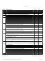
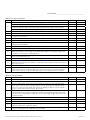
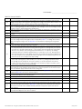
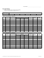
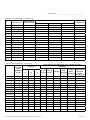
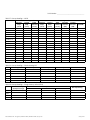
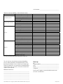
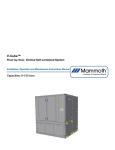
EnergyPack®, ERV5000–10000(i/e) and HRV3000–10000(i/e)
Start-up Form and Checklist
•
•
•
•
•
•
•
IMPORTANT
Complete all forms under this appendix for each
unit and email, fax or mail to Venmar CES immediately after start-up to validate warranty and to
provide valuable information for personnel performing future maintenance or for factory assistance to
address below.
Read the Installation, Operation and Maintenance
Instruction Manual and the Venmar CES Control
System Keypad Operation Guide and the Sequence
of Operation before proceeding.
Leave a copy of this report with the owner and at
the unit for future reference and permanent record.
To ensure proper operation of each unit, qualified
personnel should perform the start-up, complete
the checklist and report.
All units are functionally tested except when
shipped in multiple pieces. Start-up adjustments
may be required. If the unit is shipped as a single
piece, blowers, enthalpy wheel and compressors (if
equipped) are set up to run correctly when power
is connected. If any blower is running backwards
or compressor is making loud noises, disconnect
power and switch two leads (on three-phase power)
to ensure proper rotation and avoid damage.
If units are equipped with compressors, power must
be turned on for 24 hours prior to a call for cooling, for the compressor crank case heaters to be
energizing to prevent possible damage.
The Bacview keypad located at the control panel
will allow for manual override for start-up, mode
of operation selection and includes an internal time
clock if remote interlocks are not provided.
VCES-ASTON-SF-1B – EnergyPack, ERV5000–10000, HRV3000–10000 Start-up Form
Venmar CES Inc.
200 Rue Carter
St. Léonard d’Aston, QC
Canada J0C 1M0
Email to tech support: [email protected]
Fax: 899-319-2612
Phone: 1-866-4-VENMAR
Unit Identification Information
Project_____________________________________________
Job Name__________________________________________
Job Address
__________________________________________________
__________________________________________________
__________________________________________________
Model Number______________________________________
Serial Number_______________________________________
Tag_ ______________________________________________
Jobsite Contact_ ____________________________________
Email______________________________________________
Telephone__________________________________________
January 2014
Serial Number:______________________________________
Table E1: Pre Start-up Checklist
Checklist Item
1
Check the electrical disconnect set to the ‘Off’ position.
2
Check the split section joints are properly installed on multi-sectional units.
Check that all holes that have been made by the Installing Contractor after receiving the unit in the
casing, partitions or floor have been well sealed to prevent air and/or water infiltration.
Check the unit for obstructive packaging, objects near or in fans, dampers, energy recovery wheel, etc.
3
4
Check √
N/A
a. Check that the inside of unit has been cleaned of all debris.
Remove all retaining bolts on fan isolation bases.
a. Check that the fan impellers are rotating freely.
5
b. Check fan impellers and drive set screws. Tighten if required.
c. Check the fan bearing set screws or locking collars. Tight if required.
d. Check fan belt alignment and tension.
6
7
8
9
10
e. Check the fan flexible joint connections are well attached.
Check that the air filters are installed and clean. Replace if necessary. See Appendix F for optional
downstream high efficiency HEPA filter installation (if supplied).
a. Check all face mounted filters are attached with four clips each.
b. Check each sliding filter has a retainer at the end track and well attached blank-offs.
c. Check the filter pressure differential gauges, switches or sensors are free of dirt and set at a
value satisfactory to the end user to trigger a filter change.
Check coils if fins have been damaged in shipping, installation or building construction and are
clean. Straighten fins with a fin comb and clean coil if required.
a. Check all pipe connections are tight and that no damage has occurred during shipping or installation.
b. Check that the piping to the coils and WSHP have been completed, piping lines have been
flushed, filled, vented and tested at 1.2 times the operating pressure. Refer to Appendix B.
Scroll compressor RIS vibration isolator bolts are factory tightened to the correct torque setting for
operation and do not require field adjustment.
a. Check the refrigerant components and piping are in good condition and have no damage or
leaks from shipping or installation.
b. Check that the refrigerant lines are spaced at least 1” apart and from the compressor after shipping and installation.
c. Check that the refrigerant line clamps are still secure and have their rubber lining.
d. Check that the clearance around the air cooled condenser is within minimum clearance and the
discharge is not blocked.
Check motorized damper control arms, control rods and shafts for tightness.
a. Check that non motorized dampers rotate freely.
Check the energy recovery wheel media for any defects from shipping or installation. See Maintenance section for details.
a. Grease both pillow block bearings on the wheel(s) when grease nipples provided.
b. Check that the wheel(s) are turning freely by hand and do not bind.
c. Visually inspect the wheel(s) to ensure it is centered and does not tilt. If there is any indication of
a problem call Venmar CES Tech Support at 1-866-4-VENMAR.
d. Check that the wheel seals are properly positioned from the face of the wheel.
e. Check that the wheel purge (if present) is set to the default angle as specified in the submittal.
f. Check the mounting fasteners on the wheel(s) motor and gear reducer are tight.
g. Check the belt and pulley on the wheel drive for correct alignment, tension and set screw tightness.
11
Check the plate media for any defects from shipping or installation.
VCES-ASTON-SF-1B – EnergyPack, ERV5000–10000, HRV3000–10000 Start-up Form
January 2014
Serial Number:______________________________________
Table E1: Pre Start-up Checklist
Checklist Item
Check √
N/A
Check √
N/A
Check the heat pipe fins for any fin defects from shipping or installation.
12
a. Remove retaining bolts on heat pipe tilt mechanism.
b. Check the heat pipe flexible connection is properly attached and sealed on tilt mechanism.
c. Check the actuator control arm and linkages are tight on tilt mechanism.
13
Check that ductwork is connected, complete and free of obstructions.
14
Check that condensate drain connections have been trapped, installed correctly and filled.
Check at all unit split sections that all factory internal high and low voltage wiring connections have
been properly re-connected.
Check that all shipped loose or field supplied components have been correctly installed and wired.
15
16
17
18
19
20
21
22
23
24
25
26
Check that the wiring diagram has been marked up accordingly and left with the unit.
Check that all power supplies and control wiring have been inspected and approved by the Local
Authorities having jurisdiction.
Check all factory and field wiring connections for tightness. Tighten if necessary.
Check that all fuses are properly installed in holders.
Check the voltage at the disconnect switch against the nameplate and against phase-to-phase
readings on three-phase. If the voltage is not within 10% of rated or 2% of phase to phase, have
the condition corrected before continuing start-up.
Check that all field piping and venting installation and connections for heating and cooling options
have been completed and tested.
Set the heating and cooling enable switches to the ‘Off’ position.
Refer to Appendix D for gas-fired furnace module and Appendix G for electric coil installation and
maintenance and check that the installation is completed. Perform all gas-fired furnace and electric
coil pre start-up checks.
Check that all safety switches, overloads or other manual reset devices are reset.
If the unit is equipped with compressors, power must be turned on with the unit in ‘Off’ mode for
24 hours before start-up. This will energize crank case heaters and assure no liquid refrigerant is
present which could cause compressor damage or failure. Check that this has been completed.
Table E2: Start-up Checklist
Checklist Item
1
Before proceeding, complete the pre start-up checklist.
2
5
Check that all access panels or doors are closed.
If units are equipped with compressors, feel the compressor crank cases. They should be warm
if the disconnect has been ‘On’ for at least 24 hours. This will assure that no refrigerant liquid is
present in the crank case which could cause compressor damage or failure to occur on start-up.
Otherwise, turn the main disconnect to the ‘On’ position.
The unit can be started by using the keypad and selecting the mode of operation from the Keypad
Operation Guide and the Sequence of Operation. Disable the heating and cooling functions and
set the unit to the occupied mode to bump start the fan wheel(s) and energy recovery wheel(s) to
check their operation.
Check that dampers are operating properly.
6
Check that the fan wheel(s) and energy recovery wheel(s) are rotating in the correct direction.
7
Adjust the fan motor VFD(s) to the correct air volume/Hertz.
For occupied recirculation mode, adjust outside, exhaust and mixed or recirculation air damper
positioners to achieve the required air volumes.
Check amperage draw to each motor on each phase against motor nameplate FLA. If significantly
different, check ductwork static and/or take corrective action.
3
4
8
9
VCES-ASTON-SF-1B – EnergyPack, ERV5000–10000, HRV3000–10000 Start-up Form
January 2014
Serial Number:______________________________________
Table E2: Start-up Checklist
20
Checklist Item
Recheck the voltage at the disconnect switch against the nameplate and against phase-to-phase
readings on three-phase with all blowers operating. If the voltage is not within 10% of rated or 2%
of phase-to-phase have the condition corrected before continuing start-up.
Before activating the compressor on WSHP units, check that the water shut-off valves are open and
water is circulating through the water-to-refrigerant heat exchanger. Check the incoming line water
pressure to ensure is within design and acceptable limits.
Enable the cooling mode of operation. Check if the sound of the compressor is normal or if there is
excessive vibration.
On units with integrated air cooled condensers check condenser fans are rotating in the correct
direction.
Check all field and factory refrigerant and water piping connections for leaks and correct.
Operate the refrigerant system near full load conditions in both heating and cooling modes and
check sub-cooling and superheat against values in Appendix P, Table P1. If readings do not match,
adjust the refrigerant charge. Refer to Appendix P for information on adjusting the refrigeration
charge.
On units with WSHP, after a few minutes of operation:
a. Check the supply discharge temperature status on the keypad for cooling air delivery. Measure
the temperature difference between entering and leaving water. In cooling mode, the temperature difference should be approximately 1.5 times greater than the heating mode temperature
difference. For example, if the cooling temperature difference is 15°F [8.3°C], the heating
temperature difference should be approximately 7°F to 10°F [3.9°C to 5.6°C]. Alternatively, if a
flow measuring valve or pressure gauge connections are included, take the flow reading or pressure drop compared to the submittal information and adjust the shut-off/balancing valve in the
return line to the correct flow/pressure drop reading.
b. Measure the temperature difference between entering and leaving air and entering and leaving
water. With entering water of 60°F to 80°F [15.6°C to 26.7°C], leaving temperature should
rise through the unit. Should not exceed 35°F [19.4°C]. If the air temperature exceeds 35°F
[19.4°C], then the water flow rate is inadequate or the airflow rate may be low and a second
check may be required after air flow balancing.
On units with gas-fired furnace module or electric heating coils, check supply air proving interlock
switch setting to ensure minimum supply airflow prior to burner operation. Set the switch to open
below the minimum supply airflow on the furnace rating plate.
Enable heating options, see start-up and check out instructions in Appendix D for gas-fired furnace
module and Appendix G for electric coil and complete.
For electric heating coil option check the amp draw on each stage, the operation of the sequence
or SCR controller and the coil for any hot spots.
Check the operation of the control options provided on the unit.
21
Check the setpoints on the DDC Points Reference, adjust and record changes as required.
22
Has air balancing been completed for both occupied and unoccupied operation?
When unit has achieved steady state, take measurements and complete Start-up Readings portion
of the Start-up Report and Checklist in Appendix E. Send a copy of the completed Start-up Report
and Checklist to Venmar CES to validate warranty. Maintain a copy of the report at the unit for
future reference.
Once completed, return setpoints to original or required values, return the unit to the correct mode
of operation and adjust the time clock if required.
10
11
12
13
14
15
16
17
18
19
23
24
VCES-ASTON-SF-1B – EnergyPack, ERV5000–10000, HRV3000–10000 Start-up Form
Check √
N/A
January 2014
Serial Number:______________________________________
Start-up Readings
•
•
Allow unit to reach steady state before taking readings.
Complete based on options included with unit
Nameplate voltage
Input voltage
L1–L2
L2–L3
L1–L3
Table E3: Start-up Readings – Supply Fan
Rotation
Correct
Full Load Amps
(Nameplate Amps)
Amp Draw
L1
L2
L3
O/L Amp
Setting
Hertz
RPM
L3
O/L Amp
Setting
Hertz
RPM
Fan 1
Fan 2
Fan 3
Fan 4
Fan 5
Fan 6
Fan 7
Fan 8
Fan 9
Fan 10
Fan 11
Fan 12
Table E4: Start-up Readings – Exhaust Fan
Rotation
Correct
Full Load Amps
(Nameplate Amps)
Amp Draw
L1
L2
Fan 1
Fan 2
Fan 3
Fan 4
Fan 5
Fan 6
Fan 7
Fan 8
Fan 9
Fan 10
Fan 11
Fan 12
VCES-ASTON-SF-1B – EnergyPack, ERV5000–10000, HRV3000–10000 Start-up Form
January 2014
Serial Number:______________________________________
Table E5: Start-up Readings – Condenser Fan
Rotation Correct
Amp Draw
Full Load Amps
(Nameplate Amps)
L1
L2
L3
O/L Amp Setting
Fan 1
Fan 2
Fan 3
Fan 4
Fan 5
Fan 6
Fan 7
Fan 8
Fan 9
Fan 10
Fan 11
Fan 12
Fan 13
Fan 14
Fan 15
Fan 16
Table E6: Start-up Readings – Compressors
Full Load
Amps
(Nameplate
Amps)
Amp Draw
L1
L2
L3
After compressor has been running for 15 minutes check the
following:
Outdoor
Hot Gas Ambient Temp.
Suction Discharge
Liquid
During AC
Superheat
Bypass
Pressure Pressure
Subcooling
Cooling
Functioning
Start-up (°F/°C)
Compressor 1
Compressor 2
Compressor 3
Compressor 4
Compressor 5
Compressor 6
Compressor 7
Compressor 8
Compressor 9
Compressor 10
Compressor 11
Compressor 12
Compressor 13
Compressor 14
Compressor 15
Compressor 16
VCES-ASTON-SF-1B – EnergyPack, ERV5000–10000, HRV3000–10000 Start-up Form
January 2014
Serial Number:______________________________________
Table E7: Start-up Readings – WSHP
Waterside Cooling Mode
Entering
Leaving
Temp.
Temp.
Temp.
Difference
(°F/°C)
(°F/°C)
(°F/°C)
Entering
Temp.
(°F/°C)
Leaving
Temp.
(°F/°C)
Waterside Heating Mode
Temp.
Entering
Leaving
Difference Pressure
Pressure
(°F/°C)
(PSI)
(PSI)
US GPM
Condenser 1
Condenser 2
Condenser 3
Condenser 4
Condenser 5
Condenser 6
Condenser 7
Condenser 8
Condenser 9
Condenser 10
Condenser 11
Condenser 12
Condenser 13
Condenser 14
Condenser 15
Condenser 16
Table E8: Start-up Readings – Electric Heating Coil
Stage
L1 Amps
L2 Amps
L3 Amps
Check for Hot Pots
1
2
3
4
5
6
Table E9: Start-up Readings – Energy Recovery Wheel (ERW)
Full Load Amps
(Nameplate Amps)
Amp Draw
L1
L2
L3
O/L Amp Setting
ERW 1
ERW 2
ERW 3
ERW 4
VCES-ASTON-SF-1B – EnergyPack, ERV5000–10000, HRV3000–10000 Start-up Form
January 2014
Serial Number:______________________________________
Table E10: Start-up Readings – Gas-fired Duct Furnace
Fuel
Combustion air fan
Induced draft fan motor
Low fire
High fire
Natural Gas
Propane
Rotation correct2
Full load amps (nameplate amps)2
Amp draw L1/L2/L32
O/L amp setting2
Rotation correct
Full load amps (nameplate amps)
Amp draw L1/L2/L3
O/L amp setting
Inlet gas pressure – ” w.c.
Regulator outlet pressure – ” w.c.
Manifold press – ” w.c.
Stack CO2 – %2
Stack O2 – %2
Net stack temperature – °F/°C2
Efficiency – %2
Flame signal – mA/VDC
Supply air inlet temperature – °F/°C
Supply air discharge temperature – °F/°C1
Supply air temperature rise – °F/°C
Inlet gas pressure – ” w.c.
Regulator outlet pressure – ” w.c.2
Manifold press – ” w.c.
Stack CO2 – %2
Stack O2 – %2
Net stack temperature – °F/°C2
Efficiency – %2
Flame signal – mA/VDC
Supply air inlet temperature – °F/°C
Supply air discharge temperature – °F/°C1
Supply air temperature rise – °F/°C
Furnace #1
Furnace #2
1.Measure downstream where temperature is even in duct.
2.For IG series drum and tube gas-fired duct furnace models only.
This unit has been checked out and started according
with the above procedures and completed forms and is
operating satisfactorily. After 24 hours of satisfactory operation shut down the unit and check all foundation bolts,
shaft bearings, drive set screws, valve train and terminals.
Tighten where required.
Additional Comments:
__________________________________________________
__________________________________________________
__________________________________________________
__________________________________________________
__________________________________________________
__________________________________________________
__________________________________________________
VCES-ASTON-SF-1B – EnergyPack, ERV5000–10000, HRV3000–10000 Start-up Form
Start-up
By_________________________________________________
Company Name_____________________________________
Date_______________________________________________
Email______________________________________________
Telephone__________________________________________
Email to tech support: [email protected]
or Fax to: 819-399-2612.
January 2014