1
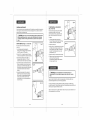
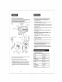
3/8-in. Variable Speed / Reversible
1 .0Volt Cordless
/ Driver
Model No.
172.64120
18.0 Volt
in Kit 9-11518
CHARGE
BEFORE
3025736
Certified
to CAN/CSA
STD 022.2
NO 60745=1,
BATTERY
FIRST USE
CAUTION:
Read, understand and
follow all Safety Rules and Operating Instructions
in this Manual before using this product.
Sears, Roebuck and Co.,
Hoffman Estates, IL 60179 U.S.A.
Visit our Craftsman ®website:
www.craftsman.com
60745=2-1,60745=2-2
conforms
to UL STD
60745-1,60745-2-1,
60745=2-2
•
•
•
•
•
WARRANTY
SAFETY
DESCRIPTION
OPERATION
MAINTENANCE
Warranty .......................................................................................................
Safety Symbols ..............................................................................................
Safety instructions ..........................................................................................
Carton Contents ............................................................................................
Description ...................................................................................................
Operation .....................................................................................................
Maintenance ..........................................................................................................
Accessories ...........................................................................................................
Parts List ...............................................................................................................
Sears Repair Parts Phone Numbers .....................................................................
The purpose of safety symbols is to attract your attention to possible dangers.
The safety symbols, and the explanations with them, deserve your careful
attention and understanding. The symbol warnings DO NOT by themselves
eliminate any danger. The instructions and warnings they give are no substitutes
for proper accident prevention measures.
Page
2
Page
3
Pages 4- 10
Page 11
Pages 12- 13
Pages 14 - 23
Pages 23 - 25
Pages 25 - 26
Page 27- 28
Back Cover
/k, WARNING:
BE SURE to read and understand all safety instructions in
this manual, including all safety alert symbols such as "DANGER", "WARNING"
and "CAUTION", BEFORE using this drill/driver.
Failure to follow all instructions
listed below may result in electric shock, fire and/or serious personal injury.
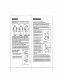
SYMBOL
Z_
ONE YEAR FULL WARRANTY
MEANING
SAFETY
ALERT
SYMBOL:
Indicates
DANGER,WARNING,OR
CAUTION. May
be used
in conjunction
with other
symbols or pictographs.
Failure to obey this safety warning WiLL result in death or
serious injury to yourself or to others. Always follow the
safety precautions to reduce the risk of fire, electric shock
and personal injury.
ON CRAFTSMAN®TOOL
if this Craftsman tool fails due to a defect in material or workmanship within one year from
the date of purchase, RETURN ITTO ANY SEARS STORE OR OTHER CRAFTSMAN
OUTLET iN THE UNITED STATES FOR FREE REPLACEMENT.
i Z_WARNING
] Failure
obey tothis
safety or
warning
CANAlways
result follow
in death
serious toinjury
yourseff
to others.
theor
safety precautions to reduce the risk of fire, electric shock
and personal injury.
i Z_ CAUTION
obey thisor safety
MAYdamage.
result in Always
personal
j] Failure
injury toto yourself
others warning
or property
follow the safety precautions to reduce the risk of fire,
electric shock and personal injury.
This warranty does not include expendable parts such as lamps, batteries, bits or blades.
if this Craftsman product is used for commercial or rental purposes, this warranty applies
for only 90 days from the date of purchase.
This warranty gives you specific legal rights, and you may also have other rights which
vary from state to state.
Sears, Roebuck and Co., Hoffman Estates, IL 60179
DAMAGE PREVENTION
SAVE THESE iNSTRUCTiONS!
READ ALL iNSTRUCTiONS!
NOTE: Equipment
are not followed.
1
/K State
WARNING:
dust created
by using
power tools
contains
chemicals
known to
the
of CaliforniaSome
to cause
cancer and
birth defects
or other
reproductive
harm.
AND iNFORMATiON
MESSAGES
These inform user of important information and/or instructions that could lead to
equipment or other property damage if not followed. Each message is preceded by the
word "NOTE:" as in the example below:
/
and/or
property damage may result if these instructions
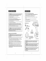
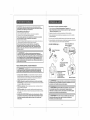
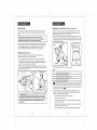
Z_WARNING:
The operation of any drill/driver can
result in foreign objects being thrown into your eyes,
which can result in severe eye damage. Before beginning
power tool operation, ALWAYS wear safety goggles or
safety glasses with side shield and a full=face shield
when needed. We recommend a Wide Vision Safety
Mask for use over eyeglasses or standard safety glasses
with side shield, available at Sears Stores or other
Craftsman Outlets.
i
i
]
manual before using this drill/driver.
Failure to follow all instructions
may result
i/Kin electric
WARNING:
BE SURE
read and
understand
shock, fire
and/or toserious
personal
injury. all instructions in this
l
]
|
operating
this drill/driver.
Failure to follow all instructions listed below may result
i in
/!kelectric
WARNING:
BEand/or
SURE serious
to read personal
and understand
shock, fire
injury. all instructions before
WORK AREA SAFETY
1. Keep your work area clean and well lit. Cluttered workbenches
invite accidents.
and dark areas
2. DO NOT operate power tools in explosive atmospheres,
such as in the presence
of flammable liquids, gases, or dust. Power tools create sparks which may ignite
the dust or fumes.
3. Keep bystanders, children and visitors away while operating
Distractions can cause you to lose control.
4. Make your workshop childproof
away when not in use.
TOOL USE AND CARE SAFETY
1. ALWAYS use clamps or other practical ways to secure and support the workpiece
to a stable platform. Holding the work by hand or against your body is unstable and
may lead to loss of control.
2. DO NOT force the tool. Use the correct tool and accessory bit for your application.
The correct tool and bit will do the job better and safer at the rate for which it is designed.
a power tool.
with padlocks and master switches. Lock tools
3. DO NOT use the tool if trigger switch does not turn it "On" or "Off". Any tool that
cannot be controlled with the trigger switch is dangerous and must be repaired.
5. MAKE SURE the work area has ample lighting so you can see the work and that
there are no obstructions that will interfere with safe operation BEFORE using your
cordless drill / driver.
4. REMOVE the battery pack from the drill/driver
or place the forward/reverse
selector switch with power lock-off in the "Lock Off" position before making
any adjustments,
changing accessories or storing the tool. Such preventive
safety measures reduce the risk of starting the tool accidentally.
PERSONALSAFETY
5. STORE idle tools out of the reach of children and other untrained
Tools are dangerous in the hands of untrained users.
1. KNOW your cordless drill/driver, Read the operator's manual carefully. Learn the tool's
applications and limitations, as well as the specific potential hazards related to this tool.
6. ALWAYS remove battery pack and store separately
is not being used.
2. STAY ALERT, watch what you are doing and use common sense when operating
a power tool.
7. When battery pack
paper clips, coins,
make a connection
together may cause
3. DO NOT use power tools while tired or under the influence of drugs, alcohol or
medication. A moment of inattention while operating power tools may result in
serious personal injury.
4. DRESS properly. DO NOT wear loose clothing or jewelry. Pull back long hair. Keep
your hair, clothing, and gloves away from moving parts. Loose clothing, or long hair
can be caught in moving parts. Air vents often cover moving parts and should
also be avoided.
5. AVOID accidental starting. Be sure trigger switch is in the "Locked OFF" position
before inserting battery pack. DO NOT carry tools with your finger on the trigger switch.
Carrying tools with your finger on the trigger switch or inserting the battery pack in tools
that have the switch in the "FORWARD" OR "REVERSE" position invites accidents.
6. Do not overreach. Keep proper footing and balance at all times. Proper footing
and balance enables better control of the tool in unexpected situations.
7. ALWAYS SECURE YOUR WORK. Use clamps or a vise to hold work when practical.
It is safer than using your hand and frees both hands to operate tool.
8. DO NOT USE ON A LADDER or unstable support. Stable footing on a solid surface
enables better control of the tool in unexpected situations.
J
|
persons.
when drill/driver
is not in use, keep it away from other metal objects like:
keys, nails, screws, or other small metal objects that can
from one terminal to the other. Shorting the battery terminals
burns to skin, sparks or a fire.
8. MAiNTAiN tools with care. Keep cutting tools such as twist drill bits sharp and
clean. Properly maintained tools with sharp cutting edges are less likely to bind and are
easier to use and control.
9. CHECK for misalignment
or binding of moving parts, breakage of parts, and any
other condition that may affect the tool's operation. If damaged, have the tool serviced
before using. Many accidents are caused by poorly maintained tools.
10. USE ONLY accessories that are recommended for this tool. Accessories that may
be suitable for one tool may become hazardous when used on another tool.
See page 25 for accessories.
11. Keep the tool and its handle dry, clean and free from
a clean cloth when cleaning. Never use brake fluids,
products, or any strong solvents to clean your tool,
the risk of loss of control and deterioration of the plastic
oil and grease, Always use
gasoline, petroleum-based
Following this rule will reduce
enclosure of the drill / driver.
ELECTRICAL
SAFETY
SERVICE SAFETY cont.
this drill/driver, Failure to follow all instructions listed below may
l operating
z_
WARNING:BE
SURE to read and understand all instructions before
result in electric shock, fire and/or serious personal injury.
1
A battery operated tool with integral batteries or a separate battery pack must be
recharged only with the specified charging stand/transformer
for the battery. A
charger that may be suitable for one type of battery may create a risk of fire when
used with another battery,
1. Use battery operated teem only with specifically
designated
other batteries may create a risk of fire.
2. Use battery only with charging stand/transformer
listed.
battery pack. Use of any
2. Tool service must be performed only at a Sears Parts and Repair Center. Service
or maintenance performed by unqualified personnel could result in a risk of injury.
3. When servicing a tool, use only identical replacement parts. Follow instructions
in the maintenance
section of this manual. Use of unauthorized parts or failure to
follow maintenance instructions may create a risk of electric shock or injury.
SPECiFiC SAFETY RULES FOR CORDLESS
DRILL/DRIVERS
1. Know your cordless drill/driver. Read operator's manual carefully. Learn its
applications
and limitations, as well as the specific potential hazards related to
this tool. Following this rule will reduce the risk of electric shock, fire, or
serious injury.
2. BE SURE that twist drill bits, screwdriver bits and other accessory attachments are
properly and securely mounted in the chuck jaws BEFORE operating the drill / driver.
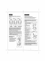
DRILL/DRIVER
CHARGING STAND/TRANSFORMER
BATTERY PACK
172.64120
CDT218GU-103/BHY41-23.5V-200mA
CDT218GU-104(ABP318GU)
3. ALWAYS carefully inspect the material you are going to drill / drive into. Drilling/driving
into nails, pipes and electrical wires can cause serious personal injury.
Can als0 use 1426101 and 140295004
Can als0 use 1323509,
1323520, 130260001,
130139020 and 130139021
4. HOLD DRILL / DRIVER by insulated gripping surfaces (handles) when performing
an operation where the tool may drill / drive into hidden wiring. Contact with a
"live" wire will make the exposed metal parts of the tool "live" and shock the operator.
3. Do not abuse the cord on the charging stand. Never carry the charging
stand/transformer by its power cord. Never pull the power cord to remove the transformer
from the power outlet. Damage to the cord or charging stand/transformer could occur and
create an electric shock hazard. Keep cord away from heat, oil, sharp edges or moving
parts. Replace damaged cords immediately. Damaged cords increase the risk of electric
shock.
SAFETY
SYMBOLS
FOR YOUR TOOL
The label on your tool may include
the following
symbols.
V .......................................................................Volts
A ......................................................................Amps
Hz....................................................................Hertz
W .....................................................................Watts
"_ ....................................................................Alternating current
--.
................................................................Direct current
no ....................................................................No-load speed
[] ....................................................................Class II construction, Double Insulated
RPM ......................................................
Revolutions per minute
SPM .........................................................
Strokes per minute
OPM.........................................................
Orbits per minute
,4',,....................................................................Indicates danger, warning or caution.
It means attention! Your safety is involved.
SERVICE
SAFETY
1. If any part of this cordless drill / driver is missing or should break, bend, or fail
in any way; or should any component fail to perform properly: have the missing,
damaged or failed parts replaced BEFORE resuming operation.
5. NEVER hold the piece being drilled in your hands or across your legs.
It is important to support and clamp the workpiece properly in order to minimize body
exposure, bit binding, or loss of control.
6. Maintain a firm grip on the drill / driver to resist starting torque.
7. Use sharp accessory bits only. For drilling in WOOD use twist drill bits, spade bits,
or power auger bits. For METAL use high-speed steel twist drill bits. For MASONRY
use carbide-tipped bits. For PLASTIC use low drilling speeds for material with a low
melting point. For SCREWDRIVlNG use the proper size screwdriving
bit for the
screwdriving
application such as Phillips, slotted and square recess bits.
8. BE SURE the material to be drilled is stationary, anchored or clamped firmly. If drilling
thin material, use a back-up block to prevent damage to the material.
9. ONLY USE the specifically listed battery pack and charging stand listed on page 6 of
this manual. Use of any other battery pack or charging stand/transformer can create
risk of injury and fire.
10. Cordless tools do not have to be plugged into an electrical outlet; therefore,
they are always in operating condition. Be aware of possible hazards when not
using your battery operated tool or when changing accessories. Following this
rule will reduce the risk of electric shock, fire, or serious personal injury.
11. Do not place battery tools or their batteries
risk of explosion and possible injury.
near fire or heat. This will reduce the
12. Do not crush, drop or damage battery pack. Never use a battery pack or charging
stand/transformer
that has been dropped or received a sharp blow. A damaged
battery pack is subject to explosion. Properly dispose of a dropped or damaged battery
pack immediately.
SPECiFiC SAFETY RULES FOR CORDLESS
DRILL/DRIVERS
cont.
SAFETY RULES FOR BATTERY CHARGING STAND/TRANSFORMER
t 3. Batteries vent hydrogen gas and can explode in the presence of a source of
ignition, such as a pilot light. To reduce the risk of personal injury, never use any
cordless product in the presence of open flame. An exploded battery can propel debris
and chemicals. If exposed, flush with water immediately.
14. Do not charge battery pack in a damp or wet location.
reduce the risk of electric shock.
Do not abuse the cord on the battery charging stand / transformer. Never carry the
charging stand / transformer by its power cord. Never pull the power cord to remove the
transformer from the power outlet. Damage to the cord or charging stand / transformer could
occur and create an electric shock hazard. Keep cord away from heat, oil, sharp edges or
moving parts. Replace damaged cords immediately. Damaged cords increase the risk of
electric shock.
Following this rule will
15. For best results, your battery pack should be charged in a location where the temperature
is more than 50°F but less that 80°R Do not store battery outside or in vehicles.
Make sure cord is located so that it will not be stepped on, tripped over, come in
contact with sharp edges or moving parts, heat, oil, or otherwise subjected to
damage or stress. This will reduce the risk of accidental falls, which could cause injury,
and damage to the cord which could result in electric shock.
16. Under extreme usage or temperature conditions, battery leakage may occur.
if liquid comes in contact with your skin, wash immediately with soap and water,
then neutralize with lemon juice or vinegar, if liquid gets into your eyes, flush
them with clean water for at least 10 minutes, then seek immediate medical
attention. Following this rule will reduce the risk of serious personal injury.
5.
RULES
FOR BATTERY
CHARGING
STAND/TRANSFORMER
A
WARNING:
READ AND UNDERSTAND ALL INSTRUCTIONS. Failure to
follow all instructions listed below may result in electric shock, fire and / or
serious personal injury.
NOTE: Before using battery charging stand / transformer, read all instructions
and cautionary
markings in this manual, on battery charging stand /transformer,
battery pack, and drill / driver using battery pack to prevent misuse of the
products and possible injury or damage.
Z_ CAUTION:
USE ONLY the specifically
designated battery charging
stand / transformer
that was supplied with this drill / driver when charging the
battery pack.The use of any other battery charging stand / transformer
could
damage the battery pack, and create a hazardous condition. See page 6.
Z_ CAUTION:To
reduce the risk of electric shock or damage
charging stand /transformer
and battery pack, charge only the
designated battery pack that was included with this drill / driver
stand /transformer.
Charging other types of battery packs may
burst, causing personal injury and damage.
to the battery
specifically
and charging
cause them to
1. Do not use the battery charging stand / transformer outdoors or expose to wet or
damp conditions. Water entering charging stand will increase the risk of electric shock.
2. Use of an attachment with this battery charging stand / transformer that is not
recommended may result in a risk of fire, electric shock, or injury to persons.
Keep cord and charging stand / transformer
housing or internal parts.
away from heat to prevent damage to
6. Do not let gasoline, oils, petroleum=based products, etc. come in contact with
plastic parts. They contain chemicals which can damage, weaken or destroy plastic.
17. SAVE THESE INSTRUCTIONS. Refer to them frequently and use them to instruct
others who may use this tool. If you loan someone this tool, loan them these
instructions also to prevent misuse of the product and possible injury.
SAFETY
cont.
i
J
3
|
J
7. An extension cord should not be used unless absolutely necessary. Use of improper
extension cord could result in a risk of fire and electric shock. If an extension cord must be
used, make sure: a) That pins on plug of extension cord are the same number, size and
shape as those on the transformer, b) That extension cord is properly wired and in good
electrical condition, and c) That you use a proper extension cord. ONLY use cords
listed by Underwriters Laboratories (UL). Other extension cords can cause a drop in line
voltage, resulting in a loss of power and overheating of charging stand/transformer. An
AWG (American Wire Gauge) size of at least 14-gauge is recommended for an extension
cord of 25-ft. or less in length. Use 12-gauge for an extension cord of 50-ft.
Extension cords 100-ft. or longer are not recommended.
8. INSPECT tool cords for damage. Do not operate charging stand with a damaged cord or
transformer, which could cause shorting and electric shock. Have damaged tool cords
repaired at a Sears Service Center.
9. Do not operate charging stand / transformer if it has received a sharp blow, been dropped,
or otherwise damaged in any way. Take it to an authorized serviceman for electrical check to
determine if the charging stand / transformer is in good working order.
10. Do not disassemble charging stand / transformer.Take it to a Sears Parts and Repair
Center when service or repair is required. Incorrect reassembly may result in a risk of
electric shock or fire.
11. Disconnect charging stand/transformer from the power supply when not in use.
This will reduce the risk of electric shock or damage if metal items should fall into the opening in
the charging stand. It also will help prevent damage during a power surge.
12. Risk of electric shock. Do not touch un-insulated portion of output connector or un-insulated
battery terminal.
13. SAVE THESE INSTRUCTIONS. Refer to them frequently and use them to instruct others who
may use this tool. If you loan someone this tool, also loan them these instructions to prevent
misuse of the product and possible injury.
This product
Z_ WARNING:
has been shipped completely
assembled.
Some dust created by using power tools contains chemicals
known to the State of California to cause cancer and birth defects or other
reproductive harm. Some examples of these chemicals are:
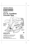
1. Carefully remove the Storage/Carrying
Bag with Drill/Driver
and Battery
Charging Stand/Transformer
and Screwdriver Bits from the box.
, Lead from lead-based paints.
o Crystalline silica from bricks and cement and other masonry products.
oArsenic and chromium, from chemically treated lumber.
3. Inspect the tool carefully to make sure no breakage or damage occurred during
shipping.
Pack,
2. Make sure that all items listed in the packing list are included.
4. Do not discard the packing material until you have carefully inspected and
satisfactorily operated the tool.
Your risk from these exposures varies, depending upon how often you do
this type of work.To reduce your exposure to these chemicals:
, Work in a well-ventilated area.
oWork with approved safety equipment, such as those dust masks that are specially
designed to filter out microscopic particles.
5. If any parts are missing, return to the nearest Sears store or other Craftsman outlet
to have the Drill / Driver replaced.
Drill / Driver with Battery Pack
PACKING
Avoid prolonged contact with dust from power sanding, sawing, grinding,
drilling and other construction activities, Wear protective clothing and wash
exposed areas with soap and water. Allowing dust to get into your mouth, eyes, or
lay on the skin may promote absorption of harmful chemicals.
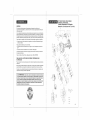
LiST (Fig.l)
Ct"t.' ',"T1aosformer
/_, WARNING:
Use of this tool can generate and/or disburse dust, which
may cause serious and permanent respiratory
or other injury. Always use
NIOSH/OSHA approved respiratory protection appropriate for the dust exposure.
Direct particles away from face and body.
2 Double Ended
Screwdriver Bits
ADDiTiONAL
RULES
FOR SAFE
OPERATION
(stored on Drill/Driver)
1
i
follow all instructions listed may result in electric shock, fire and/or serious
z_
WARNING:
BE SURE to read and understand all instructions. Failure to
personal
injury.
J
|
_RRFTSM
1. Know your drill/driver. Read operator's manual carefully. Learn the applications
and limitations, as well as the specific potential hazards related to this tool. Following
this rule will reduce the risk of electric shock, fire or serious injury.
2. ALWAYS wear safety glasses or eye shields when using this drill/driver.
Everyday eyeglasses have only impact-resistant lenses; they are NOT safety glasses.
3. PROTECT your lungs. Wear a face mask or dust mask if the operation is dusty.
4. PROTECT your hearing. Wear appropriate personal hearing protection during use.
Under some conditions noise from this product may contribute to hearing loss.
5. SAVE THESE INSTRUCTIONS. Refer to them frequently and use them to instruct
others who may use this tool. if someone borrows this tool, make sure they have
these instructions also.
_,
Storage / Carrying Bag
(51/2-in. Circular Saw with
Blade is shown in saw
manual)
Operator's
/_ WARNING:
If any parts are missing do not operate this tool until the
missing parts are replaced. Failure to do so could result in possible serious
personal injury.
/_ WARNING:
Do not attempt to modify this tool or create accessories not
recommended for use with this tool. Any such alteration or modification is misuse
and could result in a hazardous condition leading to possible serious personal
injury
Z_ WARNING:
To prevent accidental starting that could cause serious
personal injury, always remove the battery pack from the tool when
assembling parts.
10
Manual
11
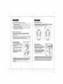
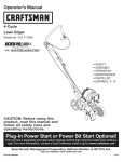
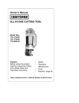
KNOWYOUR
CORDLESS
DRILL/DRIVER
(Fig.2)
i
OTE: Before
attempting
features
and safety
rules. to use this product, familiarize
Fig. 2
This Cordless Drill/Driver
yourself with all operating
TorqueAdjustmentCollar
]
Bubble Level
KeylessChuck
has the following
features cont.:
2. Forward / Reverse Power Lock-Off Switch conveniently located for easy operation.
3.3/8=in. Keyless Chuck hand tightens bits fast and secure without chuck key. Provides
positive retention of 1/16-in. to 3/8-in. shanked bits.
4.23 Plus 1 Position Adjustable Torque Clutch adjusts to automatically stop bit rotation at
desired torque setting to prevent overdriving screws. One locked position for drilling.
5. Electric Brake stops bit rotation instantly when trigger is released. Ideal when driving
screws, nuts, and bolts.
6. Bubble Level helps provide accurate right angle drilling and driving straight into workpiece.
7. Ergonomic "T" Handle Design with molded in comfort
added balance and gripping comfort.
Forward/Reverse
Selector Switch
with Power
Lock-Off
Trigg
grip provides maximum control,
8. LED Light illuminates drill / drive area for hands-free lighting in any application.
9. Fan=cooled motor provides the torque and power needed for a variety of drilling and
driving applications.
10. Durable impact=resistant housing helps protect tool from damage and reduces weight.
Latch to
Release
Battery
Pack
LED Light
Transformer
11. The Nickel=Cadmium
battery pack recharges in 3 to 6 hours under normal use.
12. Charging Stand/Transformer
when battery is charging
has LED Lights. Green indicates power On, Red indicates
13. includes: 2 double-ended screwdriver bits and storage/carrying bag for easy carrying
and storage of drill/driver, saw and accessories.
Drill
Red
Light
BatteryPack
2 Double Ended
Screwdriver Bits
(1 on each side)
Safety, performance and dependability have been given top priority in the design of this product,
making it easy to maintain and operate.
This Cordless Drill/Driver
has the following features:
1. Variable Speed 0-650 RPM (no-load speed) match high-torque driving and high speed
drilling to bit and material used in a variety of job applications. Increase pressure on trigger
switch for higher speed, decrease pressure for lower speed. Reversible to remove fasteners.
12
No. 64120,
in Kit 11518:
Chuck
3/8-in. keyless
Motor
18.0 Volt DC
Switch
Variable Speed
No Load Speed
0-650 RPM
Clutch
23 + 1 Position
Torque
Max. 160 in.-Ibs
Charger
Charge
input
Rate
120V, 60Hz AC
3 to 6 Hours
13
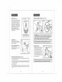
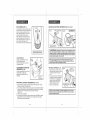
FORWARD / REVERSE SELECTOR SWITCH with POWER LOCK+OFF
(Rg 3, 3n+3b)
CHARGtNGTHE
#
Pig 3
Fig 3a
FORWARD
REVERSE
BATTERY
PACK FROM
(Fig 4)
I PI_C_ Ihe FOrWIt_I RoversB Soloclor Swllch
with Power Lock-Off tnfr_ thec_nt_r pc'_ition to
_ck thr,
powo_ off {_.o F}_ 3b, nbovo)
2 LOCt_IO
the IOICh_,_
_n o_¢b Side3
01II_0b_llO_
p_ck Depre_ {_quoozo _n)h_lches and putt
b_llorypnck out ofdti_l
(_eo F_g 4)
Fig g
fi_led _n page 6
2 _ke _Iop_wer
_upp_yl_ nerm_
h_usohold vollaffe 120 _lts _g Hz
POWER
LOCK+OFF
complot_
A'k CAUTiON_
_top befor_
Topt_vonfgot_tdtlmt_go,
chlmgtng the dfto_f_otll_b.,aysa,lowfhoch_cktocomotolt
of rotation.
DRILL/DRIVER
5 and 5_)
t Cha_g_ h_tto_y pack _nly with Ih_ ct_rg_ng
_l_nd ! _n._l_m_ f th0t writ+_,t_ppt_edwllh
3 Cor,nocl Chnlp}np _tand_ lmn_l_m_r
Io
4 Fl_co battery pack Ib ch_lglng stand, Ahgn
ml_od lib on b_llely pluckwith groove II_
cha_gh_g_frmd (See Fig 5)
The Ih[+_ p_._.itt_
o lot Ibo _0_e_t_f r_w_{c
b I_.lecal_d In IhO CENTER (Fig+3b) Thi_ po_itiotl kr,_ps
Ib_ hl_r
r;,vitchtrc=m
w_ k_ng,to_ktngbm p_wet +'OF_ _otli_g 1ha s[itect_r Switch In Ib_ +OFF"
_r CENTER po_itt_l_holp._t 0dt_c_ Ihl) possibility_f _ccltl_nt_l _f_litlg WhollIb_ 1_o}is r_t it_
U_0
REMOVE
PACK (Fig
NOT_: R_IIedOIf Wtll not _'e_ch full charge tile RrSI time they _ro charBotJ.
AIIow _vo_al cycleB (oper_tlort fottowod by _chz_glng)
f_r Ih_m to bedtime
F l_tlly
I_hm'god,
Th8 _'I[_O
cltl>n O1b_t relation I,_torw.3r_Jor reveille _r;dts co_.tro+lBdby n BP,
fcr_lor .'_vltCh
bcnl_'d nb_,ve rand lo the rea; o+the trigg0r swilch. When holding lhr_ drill/driver +ntho
notm_I opomt_n_f pl_siti_n, I+_r=d
viewed hem tl_o bltck o! the dfiIIfdriver see F_grl3, 3_
_nd 3b),thO_oloclor
_wdch r,
houldbe p_sit_c,
ned (pushed}nl+theway toth_ LEF3"+
for FORWARD rJrnormal d_ilfir_ / driving _r_d por_itionod (iou_od) oil lh_ w_y Io the
Rf_HT f_t REVER_E to _omovl_ drill bit_ antl b.'_ckOul ,'_ rOw_
[
BA3_ERY
ThP+b_tte_ pnCl_ for Ibis tOOl h_,_b0on _t'Jppt+d In n low chm'g++C_l_,_itko
n to p+revenl
possible plotllem:_ Therefore, you _hould ch_J_
_vomlght pAor to U_O.
1
g Pr_._ down on battery pack Ic. b_ _.l+fe
conl_cl_ Onb_tteW p_ck Fmgr_ plc.p_lly
wiib conifers In ch_ging r_Ii_
nd
6 TI_ chmg_
r,t_nd h_s Iwo (LED) _nd_calor
Whot_ _ bt_lio_/p_ck Is p_l l_to lho charging
_t_nd lho md LED wtitlight+
Indlcallr=g thai _0 b_t_
p_ck I_ ct_tging
bmporfy (_oo Fig 5_)
Whrlr_th_ batlery pock t_ ch_ltg0d*_nd
_omo_d tram lh_ ch_rgPngr,t_l_ th_ _l
ligh_ will go Off_Th_ _t_0r_ LED w_l come _ll
o_ly wh0n IboID i_ _ p_blk, m wi_bIh_
battery _r chntDot
ChnritP+_pStand '
Fig 5a
,C:;"
i;2..5:>+
"+'"
....
.. oo0 :j;
7 Allu; h_,lm_l u_o, 3 h_uls or tos_ el chlllgl_g
llm_ iF, mquh+ad Io hl_y r_chl_IgO balloly ;lllck
IIbt_lt_ly pock ISc_mp_toly
dlsch_IgOd.
6 hOIJ1_ nr l_Ilg_t_I I:h_t[IIn(l
tlmo I_ toqlJ_totlto fullytllcl_fflg_
blttlo_ pllck
oper_lo property, o_ Iho chorglng _f_nd doe_ nol cb_rge the b_t|ery p_ck+ mturt_
the chorglng
I transformer
b_ftoty
pr_k stgnd
fo your
r_t=r_t
' NOTE:
Within _tnnd
the w_rranly
p_rlod,_nd
If the
chotglng
LED
Itghl_ Se_rs
do notStore or
other Ctttft_m_
guile! h_r f_oo roptocom(_nl,
I
CHARGING
THE BATTERY
PACK cottt, (Fig
5 and 5a)
TRIGGER
8 Tho batlory pack wilt become _lightly warm lo lha Icuch whtlo chalging Thi_ iSno_m_,!
and dO_ hal indicate a pfob_{_m
8 Do nat piece 11_ b_llary clla_gtng cltlnd /Irans{otmof
tI will work bestal no_m_ teem t_mpemlum
P_nrl t_m_ oI _xlf_m_ ho_t or cold
18 Whoa ba!la_/pack becomes f_tLythe(god, Ur_ph_ghalloa/chalgP', g r,land i t.r_rlafarmer
horn power supply _d _omavo the h,31lacypack
CHARGING
A HOT BATi'ERY
SWITCH
(Fig
7 and 7a)
TO hJm lho _li_l ON, p_h lho F_tWald / FIOVO{SO
_aleclot Swilch wilh POWerLock O_{ to lho
FORWARD el REVERSE l_caflon II_o mr_w d_roc_onembussed or= swilch) and depress
Ih0 ld_go_" _wilch T_ luln the dli_t OFF. _o_onBathe ldgga_ switch
Fig 7
Fig 7n
PACK
Whr_nusing your lool can_m_E41_ly,th_ baOeri_s In yola ball_ty pack wi_Ihl_came hal
YOlJIfl_ou_{ltot a hDI b_llo_y prick cool d_n fe,f llpptOxIr_Olely 30 mFf_ulssbe_ta
allempl_ngl{)
r0chalga
i C_I_S
NOTE_Att_
halbldlarl_
bt_t0_ to
pack
becomn
only oCcu_
hot It shouldrt_t
when prolonged
ac_:" coat_n_u_
wllh typlctguse
u_;o.
el your ddlLIdtlver
I
FORWARD
INSTALLING
REVERSE
THE BATTERY
PACK IN DRILL,/DRIVER
(Fig, 6)
1 P_aco IhB Forward I Reverse So,eclat Switch
wltl_ Power Lock-Oft t_lo th_ con_orpr_stUonto
lock the power _tl
2 Plr_(;oIhO ba_my pack In0_odrill a_Ignhlgth_
_a_od t_bon b_ttmry pack wlIh groavo l_sidrJ
lho dr_il
3 Make au_o the lalsha_ on oath s_da of Iha
b_lory pack %n_p __nlo place, _nd the bal_o_y
pack i_ _ec_{e_I
_nthe d_i_ I dlivOr httll)I_
bDglno_ngop_flon
Z_ CAUTIO N: when pl_clt_g b_lloty pluck I_ the tool, be sure talaed rib on
batte_, p_ck _lgns wtlh the harlem o_ the drill _nd latche_ _nto pl_co proper_y,
lmproper Inst_llallon of Ihe b_ttery p_ck ea_ cause damage to lateral
co_pono_ta.
VARIABLE
SPEED
(Fig, B)
_hl_ Variable t_poed tr_gar awi_ch delivers
I_t[thor I_pe_d _*rtdtotl:lue wi_h inct_a_;_d prOBBUlOor=
lhO higg0_ GW_l_h/_d lOWer t_pOBd_nd to/quowilh
do_;roa_od ptl_aa_oon lh0 tri_0f GW_ISh
NOTE:YOt_ might hear e WhiStling O_"rl_glng
_oise hem the trigger _w_tch when oporat]ng
at I_w r_peeds. 0,J not b_ cor_emetf; thI_ tr_:t
hormat p_tt of the _wltch lu_tclton,
Z_ WARNING:
Cordlosa Battery Toots are always In operating condition when
the battery pack 1_ tnst_lled in lhe tool,Tho_elore the Forward ! Revere Selector
Swlt clt with Power Lock-Oil should _tw_yl_be tn the cooler position, focklng the
power otf, when tl_l_ tool Is not In use o_"when you are carrying It at your _lda,
ELECTRIC BRAKE
23 PLUS
To stop the drill/driver, release the trigger switch and the electric brake will stop the chuck
instantly. Ideal when driving screws, nuts and bolts.
This drill / driver is equipped with an adjustable clutch that has 24 different torque settings.
These torque settings allow you to efficiently perform various drilling and screw driving
applications.
Switch with Power Lock-Off is pushed fully to the left (forward) or to the right
NOTE:
The drill / driver will not operate unless the Forward / Reverse Selector
(reverse).
1
Avoid running the drill/driver at low speeds for extended periods of time. Running at low
speeds under constant usage may cause the drill/driver to become overheated. If this
occurs, cool the drill/driver by running it without a load and at full speed.
KEYLESS
CHUCK
1 ADJUSTABLETORQUE
CLUTCH
(Fig.
10, 10a and 10b)
To adjust the clutch, hold the handle of the drill / driver with one hand and with the other hand
turn the clutch collar to the left or right (see Fig. 10), and line the desired setting (number or
symbol) up to the embossed arrow on the top of the drill/driver's motor housing (see Fig.10a).
Fig. 10
(Fig. 9 and 9a)
The drill/driver has a keyless chuck which allows you to hand tighten or loosen accessory bits
without the use of a chuck key.
1. Grasp and hold the rear chuck collar with one hand (see Fig. 9).
2. Rotate the front of the chuck with your other hand, clockwise to CLOSE and
counterclockwise to OPEN the chuck jaws (as viewed from the front of the chuck).
The front of the chuck also has embossed "pointing hands", indicating which direction to
rotate the front of the chuck to GRIP (tighten) or RELEASE (loosen) the accessory bits in
the chuck jaws (see Fig. 9a).
Fig. 9a
OPEN "RELEASE"
I
Use the following guidelines to arrive at a proper torque setting.
Fig. 10b
1-4
For driving small screws (least torque)
5-8
For driving screws into soft material
9-12
13-16
For driving screws into soft and hard materials
For driving screws in hard woods
17 -23
For driving larger screws
For normal to heavy twist drilling into all building materials (most torque)
1. For normal drilling in wood, metal and plastics, turn and set the collar to the drilling
position symbol
/K WARNING:
Do not hold the chuck body with one hand and use the power of the
drill / driver to tighten the chuck jaws on the accessory bit.The chuck body could sJip in
your hand, or your hand could slip and come in contact with the rotating accessory bit.
This could cause an accident resulting in serious personal injury.
2. For screw driving, turn and set the collar to the desired setting 1 through 23. If you are
not sure of the appropriate setting using the guidelines in the chart (Fig. 10b), above.
,, Set the collar to the lowest setting, "1"
,, Drive and tighten the first screw
,, If the clutch ratchets before the screw is tightened, increase the torque setting and
continue to tighten the screw.
,, Repeat this process until you reach a torque setting that drives and tightens the screw
without the clutch ratcheting.
,, Use that torque setting to drive and tighten the remaining screws.
18
19
INSTALLING ACCESSORY BITS (Figs.13 and 13a) cont.
BUBBLELEVEL(Fig.11)
Inorder
toinsure
aperfect
rightangle
when
drilling
/ driving into a workpiece, you can use
Fig. 13
LJ/
Center Air Bubble between 2 lines
on Viewer for Horizontal drilling
F,g.,2
LED LIGHT (Fig. 12)
Your drill/driver has an LED light that
illuminates the drill/drive area for hands-free
lighting in any application.
/
\/
_
4
and 13a)
1. Lock the trigger switch Off by placing the Forward / Reverse Selector Switch with Power
Lock-Off in the Center position.
2. Open or close the chuck jaws to a point where the opening is slightly larger than the bit size
you intend to use. Also, raise the front of the drill slightly to keep the bit from falling out of
the chuck jaws (see Fig. 13).
REMOVING
BiTS (Fig. 14)
1. Lock the trigger switch Off by placing the
Forward / Reverse Selector Switch with
Power Lock-Off in the Center position.
2. Rotate the chuck sleeve counterclockwise
to open the chuck jaws. The chuck has an
icon of a pointing hand next to the word
RELEASE, showing the direction to release,
or loosen, the chuck jaws around the bit.
3. Remove the accessory bit.
I
Fig. 14
COUNTERCLOCKWISE
(Release Bit)
CLOCKWISE
(Grip Bit)
3
NOTE: Rotate the chuck body in the direction of the hand pointing next to word RELEASE |
to loosen the chuck jaws. DO NOT use a wrench to tighten or loosen chuck jaws.
J
3. Insert the accessory bit.
4. Rotate the chuck clockwise to tighten (see Fig. 13). The chuck has an icon of a hand next
to the word GRIP, pointing to the direction to grip, or tighten, the chuck jaws securely on
the bit
2O
I
NOTE: Rotate the chuck body in the direction of the hand pointing next to word GRIP to
tighten the chuck jaws. DO NOT use a wrench to tighten or loosen the chuck jaws.
ge
BiTS (Figs.13
/
/_ WARNING: Make sure to insert the accessory bit straight into the chuck
jaws. Do not insert the accessory bit into the chuck jaws at an angle then tighten,
as shown in Figure 13a. This could cause the bit to be thrown from the drill,
resulting in possible serious personal injury or damage to the chuck.
_
ON-TOOL BIT STORAGE (Fig. 12a)
Your drill/driver comes with
2 double ended screwdriver bits that store
on each side of the base.
ACCESSORY
WRONG
ert bit)
(totighten bit)
iNSTALLiNG
Fig. 13a
OPEN JAWS
the built-in bubble level on the top of the
drill/driver (see Fig. 11 ). The bubble level
is designed to work when drilling/driving
in horizontal position. Center the air bubble
between the two lines on the Level viewer
as shown, and the drill / driver is in a
perpendicular angle to the workpiece.
This will insure that you drill/drive straight
into the workpiece.
21
OPERATION
AS A
DRILL (Fig. 15)
Turn and set the torque clutch collar to the drilling position symbol'&_1.
desired drill bit into the chuck.
Install and tighten the
OPERATION
(Fig. 16)
AS A SCREWDRIVER
1. Install the battery pack into the drill / driver.
desired torque setting, 1 through 23. Install
2. Push the forward/reverse selector switch with power lock-off to the forward position.
bit into the chuck.
3. For drilling in WOOD, use twist drill bits, spade bits and auger bits.
4. For drilling in METAL, use high speed twist drill bits. Use a cutting lubricant when drilling
in metals. The exceptions are cast iron and brass, which should be drilled dry.
1. Install the battery pack into the drill / driver.
2.
the forward
/ reverse
selector
switch
andPush
tighten
the desired
fastener
accessory
to the forward position.
5. For drilling in MASONRY, use carbide tipped bits or masonry bits. A smooth, even flow of
dust indicates the proper drilling speed.
3. Set the collar to the lowest setting, "1"
6. Always apply pressure in a straight line with
the bit. If necessary, use the bubble levels
to drill straight into the workpiece. Use enough
pressure to keep the bit biting, but do not
push hard enough to stall the motor or
deflect the bit.
Fig. 15
7. Hold drill/driver firmly to control the twisting
action of the drill/driver.
Fig. 16
Turn and set the torque clutch collar to the
_(_r_
__
_1_
4. Drive and tighten the first screw
5. If the clutch ratchets before the screw is
tightened, increase the torque setting
and continue to tighten the screw.
6. Repeat this process until you reach a torque setting that drives and tightens the screw
without the clutch ratcheting.
7. Use that torque setting to drive and tighten the remaining screws.
8. To remove fasteners, push forward / reverse selector switch to the reverse position.
8. Move the drill bit into the workpiece, applying
only enough pressure to keep the bit cutting.
Do not force the drill or apply side pressure
to elongate a hole. Let the tool do the work.
9. When drilling hard, smooth surfaces, use a
center punch to mark the desired hole
location. This will prevent the drill bit from
slipping off-center as the hole is started.
z_ WARNING:
When servicing, use only identical Craftsman replacement parts.
Use of any other part may create a hazard or cause product damage.
10. If the drill/driver stalls, or the bit jams in the
workpiece, it is usually because the
drill/driver is being overloaded. RELEASE
TRIGGER SWITCH IMMEDIATELY and
remove bit from workpiece. Determine cause
of stalling. DO NOT PRESS TRIGGER OFF AND ON IN AN ATTEMPT TO START
A STALLED DRILL/DRIVER -THIS COULD DAMAGE THE DRILL/DRIVER.
11. Keep the motor running when pulling the bit back out of a drillled hole. This will help
prevent jamming.
/!k WARNING: ALWAYS wear safety goggles or safety glasses with side
shields when using compressed
air to clean tools, if the operation is dusty,
also wear a dust mask.
Z_ WARNING:
To avoid serious personal injury, always remove the battery
pack from the tool when cleaning or performing any maintenance.
z_ WARNiNG:Be
prepared for binding at bit breakthrough. When these situations
occur, drill / driver has a tendency to grab and kick opposite to the direction of rotation
and could cause loss of control when breaking through material. If not prepared, this
loss of control could result in possible serious injury.
NOTE: This drill / driver has an electric brake. When the trigger switch is released, the
chuck stops turning instantly. When the brake is functioning properly, sparks will be
visible through the vent slots on the housing.This is normal and is the action of the brake.
22
23
Fig. 18
GENERAL
MAINTENANCE
Avoid
using
solvents when cleaning plastic
parts. Most plastics are susceptible to damage from
various types of commercial solvents and may be damaged by their use. Use clean cloths to
remove dirt, dust, oil and grease, etc.
/_, WARNING:
Do not at any time let brake fluids, gasoline, petroleum-based
products, penetrating oils, etc., come in contact with plastic parts. Chemicals
can damage, weaken or destroy plastic which may result in serious personal
injury.
CHUCK
REMOVAL
(Figs.
17, 17a and
17b)
Fig. 17
The chuck may be removed and replaced by
a new
CHUCK
The chuck may become loose on the spindle
and develop a wobble. Also, the chuck
screw may become loose, causing the chuck
jaws to bind and prevent them from closing.
To tighten:
1. Lock the trigger switch by placing the
Forward / Reverse Selector Switch with Power
Lock-Off in the center, or OFF position.
2. Open the chuck jaws.
Fig. 18a
3. Insert a 5/16 in. or larger hex key into the chuck
and tighten the chuck jaws securely. Tap the
hex key sharply with a mallet in a clockwise
direction. This will tighten the chuck on the
spindle (see Fig. 18).
one.
1. Lock the trigger switch by placing the
Forward / Reverse Selector Switch with Power
Lock-Off in center, or OFF position.
2. Insert a 5/16-in. or larger hex key into the jaws
of the chuck and tighten the chuck jaws securely.
4. Open the chuck jaws, and remove the hex key.
5. Tighten the chuck screw. Note that the chuck
screw has left hand threads and
counterclockwise direction tightens instead
of loosens (see Fig. 18a).
3. Tap the hex key sharply with a mallet in a
clockwise direction (see Fig. 17). This will
loosen the screw in the chuck for easy removal.
4. Open the chuck jaws and remove the hex key.
Using a screwdriver, remove the chuck screw
by turning it in a clockwise direction (Fig. 17a).
Note that the chuck screw has left hand threads
and clockwise direction loosens instead of
tightens.
TO RETIGHTEN
A LOOSE
(Figs. 18 and 18a)
Fig. 17a
5. Insert the hex key back into the chuck and
tighten the chuck jaws securely. Tap sharply
with a mallet in a counterclockwise direction
(see Fig. 17b). This will loosen the chuck
on the spindle. It can now be unscrewed and
remover by hand.
/k, WARNING:
recommended
injury.
The use of attachments or accessories that are not
for this tool might be dangerous and could result in serious
1
Sears and other Craftsman _ outlets offer a large selection of Craftsman drill/driver
accessories designed for all your drill/driving applications.
Fig. 17b
You may purchase kits and sets specifically for drilling and driving, twist drill bit sets,
a variety of power drill / driving bit sets, spade bit sets, carbide-tipped masonry drill bit sets,
extra long bits, magnetic bit holders and more.
Visit your local Sears store or other Craftsman outlets or shop sears.corn/craftsman
of the accessories for your drill/driver.
24
|
25
for all
3/8-1N. VARIABLE
SPEED / REVERSIBLE
CORDLESS
DRILL / DRIVER
Model No. 172.64120
18.0Volt
(in Kit 172.11518)
BATTERIES
Thebattery
packforthistoolisequipped
c_
with nickel-cadmium rechargeable batteries.
Length of service from each charging will depend on the type of work you are doing.
The batteries in this tool have been designed to provide maximum trouble-free life.
However, like all batteries, they will eventually wear out. DO NOT disassemble battery
pack and attempt to replace the batteries. Handling of these batteries, especially when
wearing rings and jewelry, could result in a serious burn.
/
To obtain the longest possible battery life, we suggest the following:
1. Remove the battery pack from the charger once it is fully
charged and ready for use.
For battery storage longer than 30 days:
,, Store the battery pack where the temperature is below 80°F
,, Store battery packs in a "discharged" condition
See parts list or page 6 table for correct battery pack number for additional battery packs.
Order through Sears parts and repair call 1-800-4-MY-HOME
BATTERY
PACK REMOVAL
AND PREPARATION
FOR RECYCLING
To preserve natural resources, please recycle or dispose of batteries properly.
This product contains nickel-cadmium batteries. Local, state or federal laws may prohibit
disposal of nickel-cadmium batteries in ordinary trash.
Consult your local waste authority for information regarding available recycling and / or
disposal options.
/_ WARNING: Upon removal, cover the battery pack's terminals with
heavy-duty adhesive tape. Do not attempt to destroy or disassemble
battery
pack or remove any of its components.
Nickel-cadmium
batteries must be
recycled or disposed of properly. Also, never touch both terminals with metal
objects and / or body parts as short circuit may result. Keep away from children.
Failure to comply with these warnings could result in fire and / or serious injury.
\
\
d_
26
@--_
27
3/8-1N. VARIABLE
SPEED / REVERSIBLE
CORDLESS
Model No. 172.64120
18.0Volt
(in Kit 172.11518}
Item No.
1
2
DRILL / DRIVER
Parts No.
CDT118GU-1
CDT118G U-2
Part Description
Bubble Level
Brand Label
3
CDT118G U-3
F/R Button
1
4
5
101
6
7
CDT118GU-4
CDT118GU-5
CDT118GU-101
CDT118G U-6
CDT118G U-7
Driving Bit Phl/Ph2
Left & Right Housing
Motor Switch Unit
Switch
Terminal
1
1
1
1
1
8
40
41
CDT118G U-8
CDT118GU-40
CDT118GU-41
Power Supply Board
Inter Wire
Inter Wire
1
1
1
9
10
12
13
CDT118GU-9
CDT118GU-10
CDT118GU-12
CDT118GU-13
Self Tapping Screw St3.5x18
Disc Spring
Driving Bit $2/6
Reted Label
9
2
1
1
14
15
16
CDT118GU-14
CDT118GU-15
CDT118GU-16
Retaining Ring12
Spring
Clutch Setting Sleeve
1
1
1
17
18
19
20
21
22
CDT118GU-17
CDT118GU-18
CDT118GU-19
CDT118GU-20
CDT118GU-21
CDT118GU-22
Clutch Cap
Disc Spring
Bearing Cover
Self Tapping Screw St3.5x16
Chuck
Screw M5 Left X16
1
1
1
3
1
1
23
24
25
CDT118GU-23
CDT118GU-24
CDT118GU-25
Washer
Steel Ball ?3
Washer
2
15
1
102
26
27
28
CDT118GU-102
CDT118GU-26
CDT118GU-27
CDT118GU-28
Fore Housing Asm
Fore Housing
Bearing
Steel Ball ?5
1
1
1
12
29
30
103
31
32
CDT118GU-29
CDT118GU-30
CDT118GU-103
CDT118GU-31
CDT118GU-32
Ring Gear
Output Shaft Set
Motor Unit
Motor
Pinion
1
1
1
1
1
33
34
35
CDT118GU-33
CDT118GU-34
CDT118G U-35
Self Tapping Screw St2.9x16
Adapter Ring
Screw Washer Asm M3x8
4
1
2
36
CDT118GU-36
Washer
1
37
38
CDT118GU-37
CDT118GU-38
Planetary Gear I
Planet Carrier
3
1
39
104
105
CDT118GU-39
CDT118GU-104
CDT118GU-103
Planetary Gear li
Battery Pack
Charger
3
1
1
28
Qty.
1
1
29
Manual del Operador
3/8-pulg. Velocidad Variable / Reversible
1 Vo "os
Taladro / Destornillador
Inal_m "
Modelo No.
172.64120
18.0 Voltios
En Equipo
9-11518
CARGUE LA BATER|A
ANTES DE UTILIZAR POR PRIMERA
VEZ
Z_ PRECAUCION:
Lea, comprenda y siga todas las
Normas de $eguridad e Instruccionesde Operaci6n en
este Manual antes de usar este producto.
Sears, Roebuck and Co., Hoffman
Estates,
Vea nuestro sitio web de Craftsman:
www.sears.com/craftsman
3O
IL 60179 EE.UU.
3025736
Certificado
a NO 60745-1
de CAN/CSA STD C22.2,
60745-2-1.60745-2-2
se
conforma
con UL STD
60745-1.60745-2-1,
60745-2-2
•GARANT|A
• SEGURIDAD
• DESCIRPCION
• FUNCIONAMIENTO
• MANTENIMIENTO
Garantfa ............................................................................
Simbolos de Seguridad ........................................................
Instrucciones de Seguridad ....................................................
Contenidos del Cart6n ...............................................................
Descripci6n ........................................................................
Funcionamiento ......................................................................
Mantenimiento ............................................................................
Accesorios ..................................................................................
Lista de Partes ............................................................................
NQmeros telef6nicos de piezas de reparaci6n Sears .................
La finalidad de los sfmbolos de seguridad es atraer su atenci6n a los posibles peligros.
Los sfmbolos de seguridad y sus explicaciones merecen su detallada atencion y
comprension. Las advertencias de los s[mbolos por si mismas NO eliminan el peligro.
Las instrucciones y advertencias que brindan no sustituyen las medidas adecuadas de
0revenci6nde accidentes.
Pagina 32
Pb,gina 33
P_,ginas 34-40
Pagina 41
Pb,ginas 42-43
Paginas 44-53
Pb,ginas 53-55
Pb,ginas 55-56
Paginas 57-58
Contratapa
/K ADVERTENCIA: ASEGURESEde leer y comprender todas las instrucciones
de seguridad de este manual, inclusotodos los simbolos de alerta tales como
"PELIGRO",
"ADVERTENCIA"y "PRECAUCION',
ANTES de utilizar este taladro.
Si no se respetan todas las instruccionesque se incluyenen la siguiente lista se
pueden producir
descargas el_ctricas,
incendios
y/o lesiones
personales
graves.
SIGNIFICADODE SiMBOLOS
SJMBOLO DE ALERTA DE SEGURIDAD:
ADVERTENCIA O PRECAUCION.
simbolos o pictogramas.
UN AhlO DE GARANTJA COMPLETA PARA ESTA HERRAMIENTA CRAFTSMAN ®
obra dentro de un aho a partir de la fecha de compra, REGRi_SELO a LA
TIENDA SEARS U OTRO PUNTO DE VENTA CRAFTSMAN MAS CERCANO
EN LOS ESTADOS UNIDOS PARA REEMPLAZO GRATIS.
El incumplimiento
esta advertencia
seguridad
PUEDE
Z_ADVERTENCIAji resultar
en lesionesdepersonales
graves de
para
usted u otros.
Esta garantfa no incluye partes desechables tales como lamparas, pilas, brocas
u hojas.
Siempre siga las precauciones de seguridad para reducir el
riesgo de incendio, descarga el_ctrica y lesiones personales.
Si este producto Craftsman se utiliza para fines comerciales o de alquiler, esta
garantfa aplica solo para 90 dfas desde la fecha de compra.
El incumplimiento
esta advertencia
de seguridad
/KPRECAUCIONj ] resultar
en lesionesdepersonales
para usted
u otros o PUEDE
da_os
Esta garantfa le otorga derechos legales espedfios yes possible qu usted tenga
otros derechos, los cuales varfan de un estado a otto.
Sears, Roebuck and Co., Hoffman Estates, IL 60179
materiales. Siempre siga las precauciones de seguridad para
reducir el riesgo de incendio, descarga electrica y lesiones
personales.
PREVENCION
DE DANOSY
NOTA: Si no se respetan
y/o la propiedad.
3
contienequimicos conocidospor el estado de Californiapor causar cancery
[Z_ ADVERTENSIA:
Algunpolvo generado pot el uso de herramientas electricas
u otros
defectos
MENSAJES
DE INFORMACION.
Estos comunican al usuario informacion
y/o instrucciones
importantes
que si no no se
respetan, podrfan producir el da[io. Cada mensaje es precedido por la palabra "NOTA:"
como
en el siguiente ejemplo:
iGUARDE ESTAS INSTRUCCIONES!
i LEATODAS LAS INSTRUCCIONES!
de nacimiento
con otros
El incumplimientode esta advertencia de seguridad RESULTARA
en LESIONESgraves para usted u otros. Siempresiga las
precaucionesde de seguridad para reducirel riesgo de incendio,
descarga electrica y lesiones personales.
Siesta herramienta Craftsman falla debido a un defecto en el material o mano de
defectos
IndicaPELIGRO,
Pueden usarse en conjuncion
para la reproduccion.
32
l
|
USE SUS
estas
instrucciones
se puede
producir
el da5o
del equipo
Z_ ADVERTENCIA:
El funcionamiento
de cualquier
herramienta
electrica puede causar la proyeccion
de objetos
extraSos
hacia los ojos Io cual puede ocasionar daSos
graves en los ojos. Antes de porter en funcionamiento
una
herramienta
electrica,
SlEMPRE
use gafas de seguridad
o
anteojos
de seguridad
con protector lateral y protector
facial
eompleto
cuando sea necesario. Recomendamos
el uso de
una mascara de seguridad
de vision amplia para usar sobre
los anteojos
o anteojos
de seguridad
est_ndar
con protector
lateral, disponibles
en lasTiendas
Sears u otros eentros
de
ventas Craftsman.
33
/_ ADVERTENSIA:
ASEGURASE de leer y entender todas las instrucciones
en este manual antes de usar esta sierra inalambrica. No seguir todas las
instrucciones podria resultar en descargas electricas, incendio y/o lesiones
personales graves.
SEGURIDAD
DEL AREA
DE TRABAJO
1. Mantenga su _rea de trabajo limpia y bien iluminada. Los bancos de trabajo
abarrotados y las &reas oscuras invitan a los accidentes.
2. NO haga funcionar las herramientas el_ctricas en atm6sferas explosivas, como pot
ejemplo en presencia de Ii'quidos inflamables, gases o polvo. Las herramientas
electricas crean chispas que pueden encender el polvo o humo.
3. SIEMPRE mantenga alas personas que est_n cerca de las inmediaciones, niSos y
visitantes alejados al utilizar una herramienta el_ctrica. Las distracciones pueden
hacerlo perder el control.
4. Haga su taller a prueba de niSos con candados e interruptores maestros. Guarde las
herramientas bajo Ilave cuando no las utiliza.
5. ASEGURESE de que el _rea de trabajo posea una buena iluminaci6n de modo que
pueda ver el trabajo y que no haya obstrucciones que interfieran con el seguro
funcionamiento ANTES de usar su sierra.
SEGURIDAD
PERSONAL
1. FAMILIAR{CESE
con su sierra inal&mbrica.
Lea cuidadosamente
operador. Aprenda las aplicaciones
y limitaciones
potenciales
relacionados
con esta herramienta.
2. PERMANEZCA
hace funcionar
del taladro,
ALERTA, mire Io que esta haciendo
una herramienta
electrica.
el manual
del
asi como los peligros
y use el sentido
3. NO use la herramienta
cuando este cansado o bajo la influencia
medicaci6n.
Un momento de distracci6n
mientras hace funcionar
electricas podria resultar en lesiones personales
graves.
comun
mientras
de drogas, alcohol
las herramientas
o
4. VISTA apropiadamente.
NO use ropa suelta o joyas. Recoja el cabello largo. Mantenga
su cabello, ropa y guantes lejos de las piezas m6viles. La ropa suelta o el cabello largo
podrian quedar atrapados
en las piezas m6viles. Las aperturas de ventilaci6n a menudo
cubre piezas moviles y tambien deben evitarse.
5. EVITE la encendida
de manera accidental.
Asegurese
de que el interruptor este en la
posicion "OFF" ("APAGADO')
antes de encajar el cartucho de baterias. NO sostenga
herramientas
con su dedo en el interrupter. Llevar herramientas
con su dedo en el
interrupter o encajando
el cartucho de baterias con el interruptor en la posici6n
"ON"
("ENCENDIDO')
atrae accidentes.
6. No se extienda
para alcanzar sobre la herramienta.
Mantenga
el pie firme as{ como
el balance en todo momento.
Una posici6n y balance apropiados
permiten un mejor
control de la herramienta
en posiciones
inesperadas.
7. ASEGURE
SlEMPRE
SU TRABAJO.
Use abrazaderas
o un tornillo para sostener el
trabajo cuando sea pr&ctico. Es m&s seguro que usar sus manos y libera ambas manos
para operar la herramienta.
SEGURIDAD
EN EL USOY CUIDADO DE LA HERRAMIENTA
Z_ ADVERTENCIA:
ASEGURESE de leer y entender todas las instrucciones
antes de operar esta herramienta. No seguir todas las instrucciones indicadas
abajo podria resultar en descargas electricas, incendio y/o lesiones personales
graves.
1. SIEIVlPRE use abrazaderas u otra manera practica de asegurar y apoyar la pieza
de trabajo sobre una plataforma estable. Sostener el trabajo con las manos o contra
el cuerpo es inestable y podria resultar en perdida de control.
2. NO fuerce la herramienta. Use la herramienta correcta para su aplicacion. La
herramienta correcta harb, el trabajo de manera mejor y m#,s segura para Io cual fue
diseRada.
3. NO use la herramienta si el interruptor no la Eneiende o Apaga. Toda herramienta
que no puede ser controlada por el interruptor es peligrosa y debe ser reparada.
4. DESCONECTE el cartucho de hater{as del taladro / destornilio
o pone el
interruptor en la posicion "Cerrado" o "Apagado"
antes de hacer cualquier
ajuste, cambiar los accesorios o guardar la herramienta. Tales medidas prevenidas
reducen el riesgo de encender la herramienta accidentalmente.
5. GUARDE las herramientas
sin usar fuera del alcance de los niSos y otras
personas no capacitadas.
Las herramientas son peligrosas en las manos de
usuarios no capacitados.
6. SlEMPRE saque el cartucho de baterias y guardelo en un lugar separado euando
el taladro no se utiliza.
7. Cuando no se utiliza el cartucho de bater{as, mantengalo alejados de objetos de
metal como: sujetadores para papeles, monedas, llaves, elovos, tornimlos u otros
objetos de metal pequeSos que pueden hacer una eonexion de un terminal al
otro. Hacer un cortocircuito juntando los terminales de baterfa puede causar
quemandura en la piel, chispas y/o incendios.
8. DELE alas herramientas
un mantenimiento
cuidadoso. SlEMPRE mantenga las
herramientas limpiadas yen buen orden de trabajar.
9. VERIFIQUE si las piezas moviles estan desalineadas o se atascan, se rompen o si
existe alguna otra condici6n que podrfa afectar la operaci6n de la herramienta. Si esta
daSada, la herramienta debe recibir mantenimiento antes del uso. Muchos accidentes
ocurren debido a herramientas con un mantenimiento pobre.
10. USE SOLO los aeeesorios recomendados
para esta herramienta. Los accesorios
aptos para una herramienta poddan ser dahinos si se utilizan con otra herramienta.
Vea pb,gina 55 para accesorios.
11. Mantenga la herramienta y su mango secos, limpios y libres de aeeites y grasa.
Siempre utilice un paso limpio cuando limpia. Nunca utilice liquidos para freno,
gasolina, productos a base de petroleo o cualquier solvente fuerte para limpiar
su herramienta. Seguir esta norma reducirb, el riesgo de perdida de control y el
deterioro del plAstico del gabinete del taladro/destornillo.
8. NO USA LA HERRAMIENTA
SOBRE UNA ESCALERA
u otto apoyo inestable.
Una
posici6n estable sobre una supefficie s61ida permite mejor control de la herramienta
en
situaciones
inesperadas.
34
35
SEGURIDAD
SEGURIDAD EL_:CTRICA
/_, ADVERTENCIA:
ASEGURESE de leer y entender todas las instrucciones
antes de operar este taladro. No seguir todas las instrucciones indicadas
abajo podria resultar en descargas el_ctricas, incendio y/o lesiones personales
graves.
Una herramienta que funciona a bateria con bateria integrales e un cartucho de
baterfas separado se debe recargar selamente con el soporte de carga especificado
para la bated& Un cargador que puede ser apropiado para untipo de bateda puede
crear un riesge de incendio cuando se utiliza con otra bateria.
1. Utilize la sierra que tunciona a bateria dnicamente con los cartuches de baterias de
lista expecificamente designado. La utilizaci6n de cualquier otro cartucho de baterfas
puede crear un riesgo de incendio.
2. Utilice los cartuchos de bater/as _nicamente con el soporte de carga de la lista
especiticamente
diseSado.
;
H
=
OD
•
=
TALADRO
SOPORTE DE CARGA/TRANSFORIMIADO
172.64120
CDT218GU-103/BHY41-23.SV-200mA
CARTUCHO DE BATERiAS
CDT218GU-104(ABP318GU)
Tarnbienuse 1426101y 140295004
Tarnbienuse 1323509,
1323520, 130260001,
130139020 y 130139021
3. NO abuse del cable del soporte de carga. Nunca Ileve el soporte de carga per el cable.
Nunca tire del cable para sacar el soporte de carga del tomacorriente. Si se daSa el cable o
el soporte de carga se pueden producir o crear peligros de descarga electrica. Mantenga el
cable fuera del alcance de fuentes de calor, aceite, bordes afilados o partes m6viles.
Reemplace los cables daSados inmediatamente. Los cables dahados aumentan el riesgo de
descargas electricas.
SilVlBOLOS DE SEGURIDAD
PARA SU HERRAIVilENTA
La etiqueta de su herramienta puede incluir los siguientes simbolos
V......................................................................
.Voitios
A ......................................................................
Amperios
Hz....................................................................
Hercios
W .....................................................................
Vatios
....................................................................
Corriente alterna
.................................................................
Corriente continua
no....................................................................
Velocidad librede carga
[] ....................................................................
Construcci6n Clase II, DoNe aislarniento
RPM......................................................... Revolucionesper minute
SPM......................................................... Carreras (Strokes)par minute
OPM......................................................... Orbitos per minute
Z_ ....................................................................
Indica peligro, advertencia o precaucion. Significa: iii
Atenci6n!!! Su seguridad se encuentra comprometida.
SEGURIDAD
EN EL SERVICIO
1. Si cualquier parte se pierde, se rompe, se dobla o talla de cualquier forma; o si
cualquier componente no funciona adecuadamente: haga reemplazar la parte
perdida, daSada o que no funciona ANTES de utilizar nuevamente.
36
EN EL SERVICIO cont.
2. El servicio tecnico de la herramienta se debe realizar solamente en un Centre de
Servicio T_cnico de Sears. El servicio tecnico o mantenimiento que se realice per
personal no calificado podria producir riesgo de lesiones.
3. Cuando realice el servicio t_cnico de una herramienta, utilice solamente las piezas
de repuesto id_nticas. Respete las instrucciones de la secci6n de mantenimiento
de este manual. Si se utilizan partes no autorizadas o no se respetan las instrucciones
de mantenimiento, se puede crear un riesgo de descarga electrica o lesion.
REGL.AS DE SEGURIDAD PARA LOS TALADROS/DESTORNILLOS
INALAIVIBRICOS
1. Conozca su herramienta inal&mbrica. Lea cuidadosamente
el manual de
funcionamiento.
Conozca las aplicaeiones y limitaciones, asf come tambi_n los
peligros potenciales relacionados con esta herramienta. Si usted observa esta
regla reducir& el riesgo de cheque eleetrico, fuego o lesi6n grave.
2. ASEGURESE que la broea del taladro/destornillador y los demos aditamentos
est6n bien asegurados ANTES de comenzar a taladrar.
3. SIEMPRE inspeccione cuidadosamente el material que va a perforar. Perforar sobre
clavos, tuberias, y cableados electricos puede causar graves lesiones personales.
4. Agarre la herramienta per la superficie con material aislante cuando se encuentre
desempehando un trabajo deride la herramienta pueda entrar en contacto con
cableado escondido. El contacto con cables "vivos" hara que las partes met#,licas de la
herramienta que se hallen expuestas produzcan un cheque electrico al operador.
5. NUNCA sostenga en sus manes la pieza que se est_ taladrando ni en sus
piernas. Es importante soportar y aprietar la pieza trabajo apropiadamente para
minimizar la exposicion del cuerpo, el atascamiento de la broca, o la perdida de control.
6. Mantenga un agarre firme en el taladro / destornillo para resistir el comenzar del
esfuerzo de torsion
7. Utilice unicamente brocas afiladas. Para la MADERA utilice brocas helicoidales,
brocas de pala o brocas salom6nicas_ Para.METAL utilice brocas de acero de alta
velocidad y helicoidales. Para ALBANILERIA utilice brocas con punta de carburo (de
tungsteno). Para PLASTICO utilice el taladro/destornillador a baja velocidad para
materiales que tiene un bajo punto de fusion. Para DESTORNILLANDO utilice el
tamaSo correcto de broca de destornillando
para la aplicaci6n come, Phillips,
ranurado y receso cuadrado.
8. ASEGURESE que el material que va a perforar se encuentre fijo, anclado o sujetado
firmemente con abrazaderas. Siva a perforar un material delgado, utilice un bloque de
respaldo para evitar daSar el material.
9. UTIUCE SOLAMENTE el cartucho de baterfas y soporte de carga enumerados en
la p_gina 6 de este manual. Use de cualquier otro cartucho de baterias puede
crear un riesgo de da5o y incendio.
10. Las herramientas inal_mbricas no necesitan enchufarse al tomacorriente;
per Io
tanto, siempre se encuentran en eondici6n de funcionamiento.Tenga
presente
los posibles peligros cuando no se utiliza la herramienta que funciona con
bateda o cuando cambia los aceesorios. Si respeta esta regla, reducira los riesgos
de descargas electricas, incendios o lesiones personales graves.
11. No coloque las herramientas a bateria o sus baterias cerca del fuego odel calor.
Esto reducira el riesgo de explosiones y posibles lesiones.
12. No aplaste, ni deje caer, ni daSe el cartueho de baterias. Nunca utilice un
cartucho de batedas o soporte de carga que se ha caido o ha reeibido un golpe
fuerte. Una bateria daSada es susceptible a explotar. Deseche adecuadamente
una bateria que se ha caido o daSado de manera inmediata.
37
REGLAS DE SEGURIDAD
INALAMBRICOS
cont.
PARA LOS TALADROS/
NORMAS DE SEGURIDAD PARA EL SOPORTE DE CARGA DE BATERiA cont.
DESTORNILLOS
13. Las baterias descargan gas de hidrogeno y pueden explotar en presencia de una
fuente de ignici6n, tal como una luz piloto. Para reducir el riesgo de lesion personal,
nunca utilice ningun producto inaldtmbrico en presencia de llamas abiertas. Una baterfa
que estalla puede lanzar desechos y qufmicos. Si queda expuesto, lave con agua
inmediatemente.
14. No cargue el cartucho de baterias en un lugar ht_medo o mojado. Si sigue esta
norma reducira el riesgo de descarga electrica.
15. Para obtener mejores resultados, se debe cargar el cartucho de baterias en un lugar
en el cual la temperatura sea mayor a 50°F pero menor que 80°E No guarde la bateria
a la intemperie o en vehfculos.
16. Bajo condiciones
de uso o temperature extrema, se pueden producir perdidas
en la bated& Si el liquido entra en contacto con su piel, lave inmediatamente
con jabbn y agua, luego neutralice con jugo de limbn o vinagre. Si el Iiquido
entra en sus ojos, lavelos con agua limpia durante al menos 10 minutos, luego
busque atencion medica inmediatamente. Si sigue esta norma reducira el riesgo
de lesiones personales graves.
17. CONSERVE ESTAS INSTRUCClONES. Remftase a elias frecuentemente y utilicelas
para capacitar a otras personas que puedan utilizar esta herramienta. Si le presta esta
herramienta a alguna persona, prestele tambien estas instrucciones para evitar el uso
incorrecto del producto y posibles lesiones.
NORMAS
DE SEGURIDAD
PARA EL SOPORTE
DE CARGA
DE BATERiA
z_ ADVERTENCIA:
ASEGURESE de leer y entender todas las instrucciones
antes de operar este taladro. No seguir todas las instruceiones indicadas
abajo podda resultar en descargas el6ctricas, incendio y/o lesiones personales
g raves.
i
NOTA:Antes de utilizar el soporte de carga de bater{a, lea todas las instrucciones |
y las marcas de precauei6n de este manual, en el soporte de carga de la hater{a,
cartucho de hater{as, y en el taladro que utiliza el cartucho de hater[as para evitar
el uso err6neo de los productos y posibles lesiones o dahos.
1
Z_ PRECAUCION:
0NICAMENTE UTILICE el soporte de carga especificamente
deseSado que se suministr6 con el taladro cuando cargue el cartucho de bater{as.
El uso de cualquier otto soporte de carga podr{a daSar el cartucho de bater{as y
crear una condici6n peligrosa.
z_ PRECAUCION:
Para reducir el riesgo de descarga el_ctrica o daSo al
soporte de carga y el cartucho de bater{as, cargue _nicamente con el cartucho
de bater{as specfficamente
dise5ado que se incluye con este taladro /
destorniHador y soporte de carga. Cargar otro Upo de catuchos de bateda puede
causar su explosi6n y provocar lesiones y daSos personal.
1. No utilice el soporte de carga en el exterior ni exponga a condiciones de humedad.
Si ingresa agua en el soporte de carga aumentara el riesgo de descarga electrica.
2. La utilizacion de un accesorio no recomendado con este soporte de carga puede
producir un riesgo de incendio, descarga electrica o lesion alas personas.
38
3. No abuse del cable del soporte de carga. Nunca Ileve el soporte de carga por el cable.
Nunca tire del cable para sacar del tomacorriente. Si se da_a el cable o el soporte de
carga se pueden producir o crear peligros de descarga electrica. Mantenga el cable
fuera del alcance de Fuentes de calor, aceite, bordes afilados o partes moviles.
Reemplace los cables da_ados inmediatamente. Los cables da_ados aumentan el riesgo
de descargas electricas.
4. Asegurase de que el cable este ubicado de manera tal que nadie Io pise o se
tropiece y que no entre eontacto con hordes filosos o partes m6viles, calor, aceite
o que se someta de alguna otra forma a da5o o tension. Esto reducira el riesgo de
ca{das accidentales, que podrian causar lesiones, y da_os al cable que podrfan producir
descargas el(_ctricas.
5. Mantenga el cable y soporte de carga alejados del calor para evitar da5os a la
carcasa o partes internas.
6. No deje que la gasolina, aceites, productos a base de petroleo, etc. entren en
contaeto con las partes plasticas. Contienen quimicos que pueden da_ar, quitarle
solidez o destruir el plb_stico.
7. No se debe utilizar un alargue a menos que absolutamente
necesario, La utilizaci6n
de un alargue incorrecto podrfa producir un riesgo de incendio y descarga electrica. Si se
debe utilizar un alargue, asegurase de a) que los bornes del enchufe del alargue tengan
el mismo numero, tama_o y forma que los del transformador del cargador, b) que el
alargue se encuentre conectado adecuadamente yen buena condici6n electrica, y
c) utilizar un alargue adecuado. SOLAMENTE utilice los cables incluidos en la lista de
Underwirters Laboratories (UL). Otros alargues pueden causar una caida en la Ifnea de
voltaje, Io que produce p(_rdida en energia y el sobrecalentamiento del soporte de carga.
Se recomienda un tamaho de Medida de cable Americano (AWG, por su sigla en ingles)
de calibre 14 al menos para un alargue de 25 pies o menor Iongitud. Utilice un calibre 12
para un alargue de 50 pies. No se recomiendan los alargues de 100 pies o de mayor
Iongitud.
8. VERIFIQUE que los cables de la herramienta no esten daSados. No utilice el
soporte de carga con un cable daSado, que puede causar un corto cireuito y
descarga electrica. Lleve los cables daSados de la herramienta a un Centro de Servicio
Tecnico de Sears para su reparaci6n.
9. NO utilice el soporte de carga si ha recibido un golpe fuerte, se ha ca{do o se ha
da_ado de alguna otra manera. Llevelo a un tecnico autorizado para la verificaci6n
electrica para determinar si el soporte de carga funciona bien.
10. No desarme el soporte de carga. Llevelo a Centro de Repuestos y Reparaciones
Sears cuando se requiera el servieio tecnico o la reparaeion. Si se vuelve a armar
de manera incorrecta puede producir un riesgo de descarga electrica o incendio.
11. Desconecte el soporte de carga del suministro de energia cuando no se encuentra
en uso. Esto reducira el riesgo de descarga electrica o da_os en los art[culos que caen
en el orificio del soporte de carga. Tambien ayudara a prevenir daRos durante una
sobretensi6n.
12. Riesgo de descarga eleetrica. No toque la porci6n no aislada del conector de salida ni
el terminal de la bateria no aislado.
13. CONSERVE ESTAS INSTRUCClONES. Remitase a elias frecuentemente y utilicelas
para capacitar a otras personas que puedan utilizar esta herramienta. Si le presta esta
herramienta a alguna persona, prestele tambien estas instrucciones para evitar el uso
incorrecto del producto y posibles lesiones.
39
Este producto ha side enviado completamente
Z_ ADVERTENCIA:
AIgun polvo generado per el use de herramientas
el_ctricas
contiene quimicos conocido per el estado de California pot causar cancer y defectos
de nacimiento
u otros defectos para la reproducci6n.
AIgunos ejemplos de estos quimicos son:
= El plomo de las pinturas a base de plomo.
La sflice cristalina de los ladrillos, el cemento y otros productos
El arsenico y el creme, de la madera tratada qufmicamente.
ensamblado.
1. Saque cuidosamente la Bolsa de Almacenamiento/Transporte
con el
Taladro/Destornillador
y Cartucho de Baterias, Soporte de Carga/Transformador
y Brocas de Destornillador
de la caja.
2. Asegurase de que todos los artfculos enumerados en la lista de contenido.
3. Revise cuidadosamente la herramienta para asegurarse que no se ha rote o daSado
durante el transporte.
4. No tire la caja ni el material de embalaje hasta que todas las piezas sean examinadas.
5. Si algo est,. daSado o hace falta, devuelva a su tienda Sears mas cercana o al Punto de
Venta de Craftsman para que le cambien el taladro/destornillador.
de albahilerfa.
El riesgo de estas exposiciones
varia, dependiendo de la frecuencia
con que realiza
este tipo de trabajo. Para reducir su exposici6n
a estes quimicos:
=Trabaje en _.reas bien ventiladas.
* Trabaje con los equipos de seguridad aprobados, tales come m_.scaras contra el polvo que
est_,n especialmente
disehadas para filtrar particulas microsc6picas.
Evite el contacto
prolongado
con el polvo de lijadoras, sierras, pulidoras,
perforadoras el_ctricas
y otras actividades
de la construcci6n. Utilice ropa de
protecci6n y lave las _reas expuestas
con agua y jab6n. Si permite que el polvo
ingrese a su boca, ojos o permanezca
en la piel, se puede fomentar la absorci6n
de quimicos
nocivos.
LISTA DE CONTENIDO
(Fig. 1)
Taladro/Destornilllador
Cartucho de Baterias
con
Soporte/Transformador
de Carga
/_ ADVERTENClA:
La utilizaci6n de esta herramienta
puede generar y/o
esparcir polvo, que puede causar lesiones respiratorias
graves y permanentes
o de
otro tipo. Siempre utilice la protecci6n
respiratoria aprobada per el Institute
Nacional
para la Seguridad y Salud en el Trabajo/Departamento
gubernamental
de los EE.UU.
para la administraci6n
de la Seguridad
y Salud en el Trabajo (NIOSH/OSHA,
per sus
siglas en ingl6s) apropiada
para la e×posici6n
al polvo. Dirija las particulas
fuera del
alcance de la cara y el cuerpo.
2 Fresas de Destornillador
REGLAS ADICIONALES
PARA LA SEGURA OPERACION
(almacenado
en taladro
/
destornillador)
de operar este taladro.
No seguirde
todas
instrucciones
indicadas
abajo
i antes
Z_
ADVERTENCIA:
ASEGURESE
leer ylas
entender
todas personales
las
instrucciones
podria
resultar en descargas
el_ctricae, incendio
y/o lesiones
graves.
1. Conczca su taladro / destornillo.
Lea cuidadosamente el manual de operaciones.
Aprenda las aplicaciones y limitaciones, asf come tambien los peligros potenciales
especificos relacionados con esta herramienta. Si respeta esta regla, reducira, los
riesgos de descargas electricas, incendios o lesiones graves.
2. SIEMPRE utilice gafas de seguridad o protectores para la vista cuando emplee
esta herramienta. Los anteojos para todos los d_as solamente tienen lentes resistentes
a los impactos; NO son gafas de seguridad.
3. PROTEJA sue pulmones. Utilice una mascara para la cara o una mascara contra el
polvo si el trabajo es polvoriento.
4. PROTEJA su audici6n. Utilice una proteci6n auditiva personal adecuada durante el
empleo. Bajo ciertas condicines, el ruido de este producto puede contribuir a la perdida
de la audici6n.
5. GUARDA ESTAS INSTRUCCIONES. Remitase a elias frecuentemente
y utilicelas
para capacitar a otras personas que puedan utilizar esta herrameinta. Si alguien
le pide esta herramienta prestada, asegurase de que se Ileve tambien estas
instrucciones.
4O
1
|
.....
C.,FTs,
'_.
Bolsa de Almacenamiento
Transportadora
con Doble Punta
(5 1A=pulg. Sierra Circular
con Hoja mostrado
en Manual de la Sierra)
/
Manual del Operador
z_ ADVERTENSIA:
Si alguna pieza faltara o estuviera daSada, no enchufe esta
herramienta hasta que la pieza daSada sea reparada o reemplazada. Si no se hace
esto podrian ocurrir posibles lesiones personales graves.
z_ ADVERTENSIA:
No intente modificar esta herramienta o crear acccesorios
no recomendados para utilizar con esta herramienta. Cualquier alteraci6n o
modificaci6n se considera use err6neo y podria producir una condici6n peligrosa
que puede conducir posibles lesiones personales graves.
Z_ ADVERTENSIA:
Para evitar arranques accidentales que podrian causar
lesiones personales graves, siempre saque el cartucho de baterias de la
herrameinta cuando ensambla las partes.
41
CONOZCA
SUTALADRO
/ DESTORNILLADOR
Este taladro/destornillador
(Fig. 2)
]
NOTA:
Antes deoperacionales
intentar usar este
producto, familiaricese
con todos las
caracteristicas
y requerimientos
de seguridad.
Fig. 2
Cuello del Ajuste del
Esfuerzo de Torsi6n
Nivel de burbuja
Mandril sin Llave
profesional tiene las siguientes caracteristicas
cont.:
2. Interruptor Selector de Avance/ Retroceso con Bloque de Energia ubicado
convenientemente para uso f_.cil.
3. El mandril sin Ilave de 3/8 pulgada apriete las fresas por mano ra.pido y seguro sin Ilave.
Provea retencion positiva de fresas de 1/16 a 3/8 pulg.va.stago.
4. Embrague de torque ajustible 23 + 1 posiciones ajusta para detener automaticamente la
rotacion de fresa a la posicion deseada para impedir sobreatornillando de los tornillos. Una
posicion fijada para talandro.
5. Freno electrico deja rotacion de fresa instantaneamente al soltar el gatillo. Ideal al tornillar
los tomillos, las tuercas, y los pernos.
Mandfbulas de Mandril
6. Nivel de burbuja ayuda con proveer atornillando en angulo recto y taladrando recto y
preciso al pieza de trabajo.
7. Diseffo de Mango "T" ergonomico con epu_adura suave moldeada provea control
ma.ximo, ma.sbalanza y confort de agarre.
de Avance/ Retroceso
con Bloque de Energia
Seguro
para
Soltar
Cartucho
de
Baterias
LED
Interruptor del Luz
Gatillo
Transformador
Soporte de Carga
8. Luz LED enciendes el taladro / destornillador
cualquier aplicacion.
para iluminacion sin manos en
9. Motor enfriado con ventilador provea torque y poder necesario para una variedad de
aplicaciones de talandro y atornillando.
10. Carcasa durable, de alto impacto ayuda a proteger la herramienta de daSo y reduce el
peso.
11. Cartucho de baterias de niquel-cadmio recarga en 3 a 6 horas bajo el uso normal.
12. Soporte de Carga/Transformador
tiene luces LED. Luz Verde indica el poder
"Encendido", Roja luz indica que el cartucho esta.cargando.
13. Incluye 2 fresas de destornillador de doble punta, y bolsa de almacenamiento/
transportadora para Ilevando y almacenamiendo facil de taladro / destornillador, sierra y
accesorios.
Luz
Roja
Cartucho de
Baterfas
2 Fresas de
Destornillador con
Doble Punta
Se ha dado maxima prioridad a la seguridad, desempeffo y confiabilidad en el diseffo del este
producto, Io que facilita su mantenimiento y funcionamiento.
Este taladro/destornillador
profesional
tiene las siguientes
caracteristicas:
1. Velocidad variable 0-650 RPM (velocidad sin carga) se deja coincidir destornillando de
velocidad alta-torsi6n y talandrando de alta-velocidad con fresa y material usado en una
variedad de applicaciones de trabajo. Aumenta presion en el gatillo de interruptor para
velocidades mas alta, disminua presi6n para velocidades ma.s bajo. Da marcha atras para
sacar.
Taladro
No. 64120,
11518:
Mandril
3/8 pulgada sin Ilave
Motor
18.0 Voltios CC
Interruptor
Velocidad Variable
Velocidad sin Carga
0-650 RPM
Embrague
23 + 1 PosiciSn
Torsi6n
Max. 160 pulg.-
Entrada
de Cargador
[ndice De Carga
42
En Equipo
120V, 60Hz CA
3 a 6 Horas
43
libras
r
{NTERRUPTOR
SELECTOR
DE AVANCEI
ENERG{A
(Figs, 3, 3a y 3b)
RETROCIESO
CON BLOQUEO
DE
CARGANDO
EL CARTUCHO
DE BATER_AS
(Fig
5 y 5_)
So envI5 R{ cad[_cho do hairdos p_ e,_t_. he_ram_t}_h't car= u_ cond_c_ da cargo {)n_,'{
pore eviler pe_ble_ p_oblema_ P_r Io {ante. dRberla c_rgarlo una no_hR antra, do
ut|llza_
cr_rg_n_{_pRrO v_'trlOB _t_{o_t I_'unclon_ml_nm _Rguld_ do _Rc_ge) pare qUR _e
NDTA:
baledas no _{c_nzD_r_n ta carg_ complot_ ta primate _ez qu_ _o
¢_rguRil Los
_ofl_plRtamR_Io.
AVANCE
RETROCESO
BLOQUEO
{ CarglJe el ¢nlIl{cho de bRledns i'{n]camr_Rla
cel'_R{ _o_Rrl8 de c_ttO&qtlR r_Rt_l]_r_l_rl
¢of_o] {_l{ro I dR_lorRit{_dot_ o ConUhe de
}_ _{m_ _oper le_ de cR_orlmB_ck',nr_d_ en
b p&#in_ 6
2 ASRg#tesR d_ q_lR R)slJre_t_i._{iode enetgla
sea vel]aja domOs_{co norma{ 120 v_llleo
O0 Hz CA _n_cr*mao_e
DE ENERGIA
L_ dltncd_n do rol_dbtt de la fte_a avattza o r01_'r:,c
r_de ¥ _e ceel_ola coo R! intern,pro€
net0ctrJ_qt_e 0o ubtca R¢_[e paste _pe, dor y po_tofiRr del II_lol_t_plo1do gati{_o.Cu_ndo
l_o_Hen_ R{ laI_rO I deslomllladof en la po0icl6n do {uncionemiRnio normal, (y vis{o dR_do
0t dRrso dot lalRdro / deRtorni_LqLdD!
v_,_o F{_ 3, 3a y 3b), el In{eft:pip{ s0iec_or _e debadct
co{oca_ _put_I) comp_olm_nle hnde {a IZQUIERDA_ p_ra AVANZAR o l_{_.d_ar/ r_lomH{ar
r,o_rm'_tmenle,y colocar (p_l_ar} comp_o_amenlo h_cia 1_DERECHA p_ra RETROCEDER
3 ConRclR R{O_0h_IR dR{ 0opedR de C_lga RI
oomPh{sitede enorg[a
La iorco;_ poRic{_np_ra o{ tn{o_plo r [;a_oc_o_"
so ubic_ on el CENTRe. E_ht po_id_n
p_avlena el funclon_mienl_ do{ Inlorruplor do _li_l_, Io q_e BLOQUEA in _nolgI_ Co}el;at
Dn tnlorruplor seh_clor en I;_p_lsf[:i_l_"APAGADO* o C ENTRAL ayuda a todi_ctr {a
pos_bilidaddo a_ran_uoR acRid0rt_afR[t cu[mdR ne 0O_{i_iz_ la ho'immier4a
Z_ PRECAUCION:
P_ra ovlta_ qua s_ dr=£=oat ongranr=J_,siomp='R do{o q_o at
t, mReddl so drdenga r_Rmplol_montR
PARA _ETIRAR
EL CARTUCHO
BATERIAS DELTALADRO
l
DES'[ORN{LLADOR
(Fig 4)
artier de cRmb{nr IRall,Reel6/1 da {Rrolacl6tt.
DE
I Pone RI ll_lelruplor _oclo_ do Rv_nce/relIoc_o
_on bloquoo dR on_j_
on ]_1posid_rt con_tld
pore b{_qRenr R{ po(_,r (vet Fig 3b, ._obrR)
2 Ublcr_l_ _eguro_, on coda lateral del C_rh_cho
dR b_lodr_ P_l_a {apdelnha¢l_ndei_ro) IRO
_Rgt_tO_y I_tRel R,_tucho de baledoR dal teladrO
(yea F_g 4)
}
4 Co[oque el ca¢lucho de balad_ an e_
_RpRIIRdo c,"_fge AHr_O laosltf_ eievada
do{ ¢rlt_cho do bnlor(ancol_la ¢aR{{ra dol
SIlport¢,
d_ O_[_a
/
_b"
F,Rpode do carga (V_;_soFi B, 5)
5 Pmsloile e_CRdllcho de balodas Rn o{
soporte do cm'ga aoa£_u_&ndose de ql_e l#_
Fig Ba
,/::/
¢Rfllf_ClOf_Be er_gR_cliRrl RdOCNIId_O_IR
6 El so{>o_IRde cargo t_enR de._(LED} {ucos
tndloadoreo_ un}]vRfdO y le3B IO_ C_ando
SOpO;_Rel _ll{_chR dR b_tedas OR 01
_#po_le do cargo, {a lez tRIa LED or_cior_d0,
ImJ{ca[ qua el carh_ch# do balodas se cargo
agmp_ndamQ{llR (Vaf F{g 5a}, ClmRde R{
carlt_cho
esl_cat,ado y _,cado do{sop#r{,{
d8 _:m'ga, {nh_z tOjaL_D ,'_paga Ln {uz
verde LED aRCter_daoRlemRf_te S{l_ay
pfObl_m_ Roe R{_'_._h_ho
dR bolot{_3_ 0 _31
._op_rlo d_ ca_a
7 O(_Bpudsdo{ o'_oa_{tmBI, SR mquio_all 3 hems o menoR d_ ca_ga pata c_rgar
RR_p{R{_mRI{IR el carluc{'_ d0 batoda_, St Re dR0_a;3_a cvmp_R{_4r,
Rt_{_RI _r{l_flo
do
caducho de baloda_
L_D del =oporto do cRt[Ja o #1 _opotlo do cargo no cn_'gael _etle¢ho do b_ter[R_
tRgtet;R e__oporte do ca_'ge y ol cattu¢_o do bala_'ta¢, R _ln comatose 5e_t_ u otto
NOTA: Ade_{m e perl6do do garnnl{a, _1no _uncfonnr_ ndeeuadr=men{e I_s h_cea
peele de vonlR CrRft_man p_ra 0U reposlcldn graliR.
INTERRUPTER
DEL GATtLLO
(Fig
7 y 7a)
P_r_ ENC_NDER e! li_t_dm, emp_jo eltnlmr_ploc SOl_Clo_de Av{tnce/_otmce_
con
Bloqu_o (to EtlerDia B ta ubicl_ci6_ AVANCE o RETROCESO (yea ta d=focci_n de la tEoch_
g_Ib_da or_el[ntec{uptoQ
y puls_09l_I_f,_uplo_
dolg_I;llo
Pa_ APAGAR IBla1_d_om_o_la
ol intm';uplo_ d_l gol_llo
Fir3 7
PARA
CARGAR
UN
CARTUCHO
DE BATERfAS
FI!l 7_t
CALIENTE
CU,_nBo ultl_z_m=h_,rmmlenta c_ntir_u_menlo. !_s bnlodn,,; dal cn_tt_chod_ bnt_t_
_e
NOTA: Un c_Iucho de b_t atl_ts c_tlerlto soll_mente o_t_
c_lndo 01 uso contIleuo
do ell t _I_d_'O/ dest_rhffio_!or ¢t_U_OqUO I_l_ bote_|O_ _O P.,_tlnelen He ocU=-ren bl_n
n;_Ftslllnc
_t= llOnllll
o_
AVANCE
PARA INSTALAR
EL CARTUCHO
DE BATERtAS EN EL
TA LADRO l DESTORNILLADOR
(Fig, 6)
I Pone el InlerruptorSeteclor
_e Awnco/Ralmceso
co_ Bloqueo do Et_ergI_ en li_ position cenl_l
pP,_abloquo_,ro_p_dor
2 C_IOqUOel CI=HUChOde b_lofia=_ nn el
l,'_n
d m I d_storltH_aclor,nllnaa_l_ _1__III_
3 A_D_/mit) quo Io_ ctoffo_ so encnlei_ a pre_6n
II_Clr_
luffar,
y Ol_Ill_i_Odo bnlerlaso _._,ngula
e_ _It_91_Lfftt
ffnIO!_
LII)
_tlIt}_3Z,lt li_
OI}offt_l_n
a_ eg_,ra_e de que Ioes I,'_1_elewda _I Corlucho de baterla_ I_e _¢cu_nlre
_lineadlt Con la pert_ Inferior del lal,_dm Y lor_ st!gt_roll O_ _ lugor _e m_nom
edec_do,
L_I In_l_l_l_n
l_otto_-t_t
dol elcartgcho
cartucho de
' Z_
PRECAUCISN:
Cll_ndo
coloqtlo
debetel'l_s
br=let_B_pue_e
On el €_us_r
lain[lie.
d_fior_ a los eompor_entes Internes,
VELOCIDADVARIABLE
RETROCESO
(Fig
B)
El inte_'uplm- del _li_lode volocidad w_l_ble onlmga
un_ velocid_d y un or_luorzo do tort_]6n m_l_ eltoJ_
con I_pfo_i_ C_O_iet_t
e, y Utlil V gIt_¢
|_;ll_ll
y 1111
eshte_o do tO_I6_ m_ bolos con pmsi_
di_minlJ]d_
NOTE; EO p_obeble que eecuche un ruldo de
"]
eilbt_fo o zumbido quo pmvlono del Inlorrupl_r
/
do geilllo cut,ride lo ullll_ I1velolcded0_ bnJ_s,[
No _;e pr_cupe;
esto os una perle normal do I_|
funci_n dol inlorr_pl_r
J
Z_ ADVERTENSIA:
L_s H_rtnmlonl0s IntH_mbric_
siempro so encuemrnn
an condlclonea de Iunclonam{onto cu_ndo 01cerlucho de betedas eo lnsta]a On
In hermmlon_n, Per to t_nto, et l_lorrupl_r
_oleclor do AvnneelRetrocer_o con
Bloqueo de EnenlJ_edebo _e¢ {_nit_pOg[cl6n centrtt9 _uondo Itl
herr_mtenle 110el_
_dentro u_o y u_lod Io osld IIoVnndoel Indo _uyo,
FRENO ELECTRICO
EMBRAGUE
Para parar el taladro / destornillador, suelta el interruptor del gatillo y el freno electrico deja
rotaci6n del mandril instanta.neamente. Esto es ideal para desternillando tornillos, tuercas y
pernos.
Este taladro / destornillador se equipe con un embrague adjustable que tiene 24 diversas
configuraciones del esfuerzo de torsion. Estas configuraciones del esfuerzo de torsion te
dejan para realizar varios aplicaciones de perforar y atornillar.
Para ajustar el embrague, sostenga la manija del taladro / destornillador con una mano y con
la otra mano tuerce el cuello del embrague a la izquierda o al la derecha (ver Fig. 10), y alinee
la configuraci6n deseada (numero o simbolo) a la flecha grabada en la tapa de la carcasa del
taladro / destornillador (ver Fig. 10a).
completamente
el interruptor selector de avarice / retroceso con bloqueo
NOTE:
taladro
/ destornillador
a menos(retroceso).
que se pulse
energ{a Elhacia
la izquierda
(avance)noofuncionara
hacia la derecha
de
i
Evite hacer funcionar el taladro / destornillador a velocidades bajas durante periodos de
tiempo prolongados. Si hace funcionar a velocidades bajas bajo uso constante puede
causar el sobrecalentamiento
del taladro / destornillador. Si esto ocurre, enfrfe el
taladro / destornillador haciendolo funcionar libre de carga y a plena velocidad.
MANDRIL
SIN LLAVE
(Fig.
DE PAR AJUSTABLE
Fig. lO
23 m&s 1 (Fig. 10, 10a y 10b)
Disminua
_Fi
_-
9 y 9a)
El taladro / destornillador tiene una mandril sin Ilave que le permite ajustar o afiojar
manualmente las fresas sin el uso de una Ilave de mandril.
1. Agarre y sostenga la abrazadera posterior del mandril con una mano (vease Fig. 9).
2. Gire la parte frontal del mandril con la otra mano, en el sentido de las agujas del reloj
para CERRAR y contra el sentido de las agujas del reloj para ABRIR las mandibulas del
mandril (segun se visualiza desde el frente del mandril).
El frente del mandril tambien tiene manitos estampada en relieve indicando la direcci6n girar
al frente del mandril para SUJETAR (aprietar) o SOLTAR (aflojar) las fresas accesorias de las
mandfbulas del mandril (vea Fig. 9a).
Fig. 9a
ABRIR "SOLTAR
I
Use the following guidelines
to ardve at a proper
torque setting.
Fig. lob
1- 4
Para ajustar tornillos peque_oa
5- 8
Para ajustar tornilloe en material
(par menor)
blando
9 - 12
13 - 16
Para ajustar tornilloa en materials blandoe
Para ajustar tornilloe en maderas durae
17 - 23
Para ajustar tornillos mas grandee
y duros
Para el taladro helicoidal normal a pesado en materials de construcci6n (par mayor)
1. Para taladrando normal en madera, metal y plAsticos, gire y configure la abrazadera en
el simbolo de posici6n de taladro _.
CERRAR"SUJETAR"
z_ ADVERTENSIA:
No sostenga el cuerpo del mandril con una mano y utilice la
energia del taladro / destornillador para ajustar las mardazas en la broca accesoria. El
cuerpo del mandril pudiese deslizar en su mano, o su mano deslize y viene en contacto
con la broca accesoria girando. Puede causar un acidente, resultando en lesiones
personales graves.
2. Para ajustar tornillos, gire y configure la abrazadera en la configuraci6n de 1 a 23
deseada. Si no esta. seguro de la configuraci6n apropiada utilizando las pautas de la
table (Fig. 10), proceda de la siguiente manera:
,, Configure la abrazadera en la configuraci6n
mas baja, "1"
,, Atornille y ajuste el primer tornillo
,, Si el embrague atasca antes de que se ajuste el tornillo, aumente la configuraci6n
del par y contint]e ajustando.
,, Repita este proceso hasta Ilegar a la configuraci6n
tornillo sin que el embrague se atasque.
,, Utilice esa configuraci6n
48
del par que atornilla y ajusta el
de par para atornillar y ajustar los tornillos restantes.
49
NIVELDEBURBUJA
(FIG.11)
Afindeasegurar
un_mgulo
rectoperfecto
cuando
setaladre/atornilla
enunapiezadetrabajo,
puede
utilizar
elniveldeburbuja
ubicado
encima
del
taladro
/ destornillador (vea Fig. 11). El nivel de
PARA INSTALAR LAS FRESAS COMPLEMENTAS (Figs. 13 y 13a) cont.
Fig. 13
ABRA LAS MORDAZAS
(introducir
Fig. 13a
INCORRECTO
burbuja esta. diseRado trabajar cuando se
taladra / atornilla ya sea en posicion horizontal.
Alinease a la burbuja entre los dos lineas, y el
taladro / destornillador esta en un a.ngulo recto a
la pieza de trabajo. Esto asegurara, que
taladre / atornille en linea recta a la pieza de trabajo.
Alinease la burbuja de aire entre las
dos lineas para taladre horizontal,
F,g.,2
LA LUZ LED (Fig. 12)
Su taladro / destornillador tiene una luz
LED que enciende el Area de
taladrar / destomillar para la luz sin mano
en cualquier aplicaci6n.
ALMACENAMIENTO
DE FRESAS
/
\/
PARA SACAR LAS FRESAS
' nto
En Herramiento
LAS FRESAS
Asegurese de introducir la fresa complementaria en linea
recta en las mordazas del mandril. No introduzca la fresa complementaria
en las
mordazas del mandril a un angulo y luego ajuste, segun se muestra en la Figura
13a. Esto podr{a causar que la fresa sea arrojada del taladro y producir posibles
lesiones personales graves o daifio al mandril.
NOTA: Gire el cuerpo del mandril en la direccibn que seSala la mane con la
marca GRIP (SUJETAR) para ajustar las mordazas del mandril. NO utilice una
Ilave para ajustar o aflojar las mordazas del mandril.
EN
HERRAMIENTO
(Fig. 12a)
Su taladro / destornillador viene con 2 fresas
de destornillador con doble punta
almacenado en cada lado del base de
herramienta.
PARA INSTALAR
Z_ ADVERTENCIA:
COMPLEMENTAS
(Figs. 13 y 13a)
1. Bloquee el interruptor de gatillo colocando el Interruptor selector de avarice / retroceso
con bloqueo de energia en la posicion central.
2. Abra o cierre las mordazas del mandril hasta un punto en el cual la abertura es levemente
mayor que el tama_o de la fresa que intenta utilizar. Tambien, levante el frente del taladro
levemente para evitar que la fresa se salga de las mordazas del mandril
(vease Fig. 13).
3. Introduzca la fresa complementa.
4. Gire el mandril en el sentido de las agujas del reloj para ajustar (SUJETAR) las mordazas
del mandril bien en la fresa. El mandril tiene un mano en relieve al lado de la palabra
GRIP, puntando ala direcci6n para sujetar.
5O
(Fig. 14)
Fig. 14
1. Bloquee el interruptor de gatillo colocando
el Interruptor selector de avance / retroceso
con bloqueo de energia en la posicion
central.
2. Gire el cuerpo del mandril en sentido de las
las agujas del reloj para abrir las mordazas.
El mandril tiene un mane estampado en
relieve al lado de la palabra RELEASE
(SOLTAR), mostrando la direccion de
aflojar las mordazas en la fresa.
3. Saque la fresa complementaria.
CONTRA EL
SENTIDO DEL RELOJ
(Soltar la fresa)
I
EN EL SENTIDO DE
LAS AGUJAS DEL RELOJ
(Sujetar la fresa)
3
RELEASE para aflojar las mordazas del mandril. NO UTILICE una Ilave para ajustar o
i aflojar
NOTA: Gire
el cuerpo del
del mandril.
mandril en la direccibn que seSala la mane con la marca
las mordazas
51
1
|
FUNClONAIVIENTO
COIVIOTALADRO
(Fig. 15)
Gire y configure la abrazadera del mandril de par hacia el simbolo
Instale y ajuste la fresa para taladro deseada en el mandril.
1. Instale el cartucho de baterfas en el taladro / destornillador.
2. Empuje el interruptor
selector
de avance/retroceso
_
de posici6n
de taladro.
con bloqueo en la posici6n de avarice.
3. Para taladrar MADERA, utilice fresas helicoidales, fresa de pala y fresas para madera.
4. Para taladrar METAL, utilice fresas helicoidales de alta velocidad. Utilice un lubricante para
cortes cuando taladra metales. Las excepciones son el hierro fundido y laton, que se deben
taladrar en seco.
5. Para taladrar MAMPOSTER{A,
utilice fresas con punta de carburo o fresas para mamposteria.
Un flujo uniforme y parejo de polvo indica la velocidad de taladro apropiada.
6. Siempre aplique presi6n en linea recta con la
fresa. Si es necesario, utilice los niveles de
burbuja para taladrar en Ifnea recta en la pieza
de trabajo. Utilice suficiente presi6n para que
la fresa siga calando, pero no empuje
demasiado fuerte para no atascar el motor o
desviar la fresa.
Fig. 15
saque la fresa del orificio taladrado.
2. Empuje el interruptor selector de
avarice / retroceso a la posici6n de avarice.
3. Pone el cuello a la configuraci6n, "1".
4. Atornilla y apreite el primero tornillo.
5. Si el embrague trinquete antes que el
tornillo esta aprietado, aumenta la configuraci6n y sigue aprietando el tornillo.
8. Para retirar los sujetadores,
poslclon
una configuraci6n
de par para atornillar
empuje
el interruptor
selector
y apriete
el tornillo
todos los mas tornillos.
de avarice
/ retroceso
a la
inversa.
los
0
z_ ADVERTENCJA:
Esto ayudara
SlEMPRE utimice galas de seguridad o anteojos de
seguridad con protecciones laterales cuando utilice aire comprimido
para limpiar
las herramientas.
Si la actividad es polvorienta, tambi_n utilice una mascara
contra el polvo.
z_ADVERTENClA:
Para evitar lesiones personales graves, siempre saque el
cartucho de bater{as de la herramienta cuando limpia o realiza cualquier
mantenimiento.
AADVERTENClA:
Este preparado para el atascamiento en la penetracion de la
fresa. Cuando estas situaciones se presentan, el taladro / destornillador tiene tendencia
al agarre y retroceso en la direccion opuesta de la rotacion y puede causar la perdida de
control cuando se penetra el material. Si no esta preparado, esta perdida de control
podria producir posibles lesiones graves.
interruptor de gatillo, el mandril detiene el giro instantaneamente. Cuando el freno
funciona
adecuadamente,
las chispas
seran
visibles
a tray,s Cuando
de las ranuras
NOTA: Este
taladro / destornillador
tiene
un freno
electrico.
se sueltadeel
ventilacion de la carcasa. Esto es normal y es la accion del freno.
52
y aprietar
que atornilla
•/_ ADVERTENCIA:
Cuando realice el servicio tecnico, utilice solamente
repuestos de Craftsman identicos. La utilizaci6n de cualquier otto repuesto
puede crear un peligro o causar un daSo al producto.
10. Si se atasca el taladro / destornillador, o se traba la fresa en la pieza de trabajo,
generalmente es debido a que el taladro / destornillador
esta sobrecargado. SUELTE
INMEDIATAMENTE
EL INTERRUPTOR DE GATILLO y saque la fresa de la pieza de
trabajo. Determine la causa del atascamiento. NO PRESIONE Y SUELTE EL GATILLO
PARA INTENTAR ARRANCAR
UN TALADRO / DESTORNILLADOR
ATASCADO:
ESTO PODRiA DANAR EL TALADRO / DESTORNILLADOR.
cuando
Fig. 16
Gire y configure la abrazadera de par del
embrague en la configuraci6n del par
deseada, 1 a 23. Instale y ajuste la fresa
complementaria de sujetador en el mandril.
1. Instale el cartucho de baterfas en el
taladro / destornillador.
7. Utilice este configuracidn
8. Mueva la fresa en la pieza de trabajo, aplicando
Onicamente la presion suficiente para que la
fresa siga cortando. No fuerce el taladro ni
aplique presi6n lateral para alargar un orificio.
Deje que la herramienta haga el trabajo.
9. Cuando taladre superficies duras y lisas,
utilice una perforaci6n central para marcar
11. Mantenga el motor funcionando
a prevenir el atascamiento.
COMO
(Fig. 16).
6. Repeta ese proceso hasta que alcanzas
sin trinquete del par.
7. Sostenga el taladro / destornillador
firmemente
para controlar la acci6n de torsi6n del taladro /
destornillador.
la ubicaci6n del orificio deseada. Esto evitardt
que la fresa se deslice fuera del centro cuando
se inicia el orificio.
FUNClONAMIENTO
DESTORNILLADOR
53
Fig. 18
MANTENIMIENTO
GENERAL
Evite la utilizacion de solventes cuando se limpian las partes pla.sticas. La mayorfa de los
pla.sticos son susceptibles a da_os de varios tipos por los solventes comerciales y se pueden
da_ar con su utilizacion. Utilice pa_os limpios para sacar la suciedad, polvo, aceite y grasa, etc.
z_ ADVERTENCIA:
EN NINGON momento permita que liquidos para frenos,
gasolina, productos a base de petr61eo, aceites penetrantes, etc. entren en
contacto con las partes plasticas. Los quimicos pueden dafiar, debilitar o
destruir el plastico, Io que puede producir una lesi6n personal grave.
PARA SACAR
(Figs.
EL MANDRIL
Fig. 17
17, 17a y 17b)
1. Bloquee el interruptor de gatillo colocando el
interruptor selector de avarice / retroceso con
bloqueo de energia en la posici6n central o en
la posici6n APAGADO.
2. Introduzca una Ilave hexagonal de 5/16-pulg.
o mayor en las mordazas del taladro y ajuste
bien las mordazas del mandril.
Para ajustar:
1. Bloquee el interruptor de gatillo colocando el
interruptor selector de avarice / retroceso con
bloqueo de energia en la posici6n central o
APAGADO.
2. Abras las mordazas del mandril.
Fig. 18a
Fig. 17a
4. Abra las mordazas del mandril y saque la Ilave
hexagonal. Utilizando un destornillador, saque
el tornillo del mandril gir_ndolo en el sentido
de las agujas del reloj (vease Fig. 17a).
Nota que el tornillo del mandril tiene rosca
hacie a izquierda y la direcci6n con el sentido
de las agujas del reloj afloja en vez de aprietar.
5. Introduzca la Ilave hexagonal nuevamente en el
mandril y ajuste bien las mordazas del mandril.
De un golpecito seco con un mazo en el
sentido contrario alas agujas del reloj
(vease Fig. 17b). Esto aflojar_t el mandril del
husillo. Ahora se puede desenroscar
manualmente.
El mandril puede aflojarse del husillo y comenzar
a oscillar. Tambien, se puede aflojar el tornillo del
mandril, Io que causa que las mordazas del
mandril se atasquen y evite su cierre.
3. Introduzca la Ilave hexagonal 5/16-pulgada o
mb_sgrande en el mandril. De un golpecito seco
a la Ilave hexagonal con un mazo en el sentido
de las agujas del reloj. Esto ajustardt el mandril
en el husillo (ver Fig. 18).
4. Abra las mordazas del mandril y saque la Ilave
hexagonal.
5. Apriete el tornillo del mandril. Nota que el tornillo del mandril tiene rosca hacia la
izquierda y la direcci6n contra el sentio de las agujas del reloj aprieta en vez de aflojar
(vea Fig. 18a).
Se puede sacar el mandril y reemplazar por
uno nuevo.
3. De un golpecito seco a la Ilave hexagonal con
un mazo en el sentido de las agujas del reloj
(vease Fig. 17). Esto afjojarb, el tornillo del
mandril para sacarlo con facilidad.
VOLVER A AJUSTAR UN MANDRIL
FLOJO (Figs. 18 y 18a)
/!k ADVERTENSIA:
El use de repuestos o accesorios que no son
recomendados para esta herramienta podria resultar peligrosa y podria causar
lesiones graves.
Las tiendas Sears y otros puntos de venta Craftsman ofrecen una gran selecci6n de
accesorios para taladros / destornilladores Craftsman dise_ados para aplicaciones de
taladros / destornilladores.
Fig. 17b
Puede comprar equipo y conjuntos especfficamente para taladrar / destornillar, conjuntos
de fresas helicoidales, conjutos de fresas (para destornillador) de engaste, conjuntos de
fresas de pala, conjuntos de fresas con punta de carburo para mamposterfa, fresas
extra-largas, soportes para fresas magneticos y mas.
Visite su comercio Sears local u otros puntos de venta Craftmsan o compre en
sears.corn/craftsman para todos los accesorios para su taladro / destornillador.
54
55
18,0 Voltios Taladro / Destomillador
Inalambrico
de Velocidad
Variable / Reversible de 3/8 Pulgadas
BATER[AS
Elcartucho
debateffas
paraestaherramienta
estAequipado
conbateffas
de
nfquel-cadmio
recargables.
Laduraci6n
deservicio
decadacargadependerA
deltipode
trabajo
querealice.
Sehartdiseffado
lasbateffas
deestaherramienta
paraproporcionar
unavidaOtil maxima
IVlodelo No. 172.64120
(en el kit 172.11518)
c_
libre de complicaciones. Sin embargo, como todas las bateffas, con el tiempo se gastarAn.
NO desarme el cartucho de bateffas ni intente reemplazar las bateffas. Si manipula estas
bater[as, especialmente cuando utiliza anillos y joyas, podrfa producir quemaduras graves.
Para obtener una posible vida Otil de la bateffa mas prolongada, sugerimos Io siguiente:
1. Saque el cartucho de las baterfas del cargados una vez que este totalmente cargado
y listo para utilizar.
Para guardar las bateffas por mas de 30 dfas:
, Guarde el cartucho de las bateffas en un lugar en el cual la temperatura sea menor a
80OF
, Guarde los cartuchos de bateffas en una condici6n "descargada"
Vea la lista de partes en la mesa en la pAgina 6 para el nt)mero correcto para cartuchos
de baterias adicionales.
Hace un 6rden por Sears Partes y Repuestos, llama 1-800-4-MYHOME
PARA SACAR EL CARTUCHO
EL REClCLAJE
DE BATER[ASY
PREPARAR PARA
Para conservar los recursos naturales, pot favor recicle o deseche las bateffas de manera
adecuada.
Este producto contiene bateffas de niquel-cadmio. Las leyes locales, estatales o federales
pueden prohibir que se desechen las bateffas de nfquel-cadmio en la basura ordinaria.
Consulte con la autoridad de desechos local para obtener informaci6n con respecto alas
opciones de reciclaje y/o desecho disponibles.
/K ADVERTENCIA:
Sobre retiro, cubre los terminales del cartucho de bater{as
con cinta adhesiva resistente. No procure destruir o desensamblar el cartucho de
baterias ni remover ningun de sus components.
Baterias de niquel-cadmio
tienen
que set reciclado o dispuesto adecuadamente.Tambien,
nunca toca los dos
terminales con ojectos metales y/o partes de cuerpo, porque occura cortocircuito.
Mantengalos lejos de niffos. Incidente de conformarse con estas advertensias
resultarfi en fuego y/o lesiones graves.
c_
4_
56
57
18,0 Voltios Talad ro / Destomillador
Inalambrico
de Velocidad
Variable/Reversible
de 3/8 Pulgadas
Modelo
No. del item
1
2
3
4
Nt_mero de Parte
No. 172.64120
Descripcibn
(en el kit 172.11518)
de Parte
Cantidad
CDT118GU-1
CDT118GU-2
CDT118GU-3
CDT118GU-4
Nivel de Burbuja
Etiqueta de Marca
Boton de Avance / Retroceso
Fresa de Destornilar Phl/Ph2
1
1
1
1
5
101
6
7
8
CDT118GU-5
CDT118GU-101
CDT118GU-6
CDT118GU-7
CDT118GU-8
Carcase Izquierda y Derecha
Unidad de Interruptor de Motor
Interruptor
Terminal
Placa de Suministra de Poder
1
1
1
1
1
40
41
CDT118GU-40
CDT118GU-41
Alambre Interior
Alambre Interior
1
1
9
10
12
CDT118GU-9
CDT118GU-10
CDT118GU-12
Tornillo Autoempezando St 3.5 X 18
Resorte de Disco
Fresa de Destornilar $2/6
9
2
1
13
14
15
CDT118GU-13
CDT118GU-14
CDT118GU-15
Etiqueta Clasificado
Anillo de Reteniendo 12
Resorte
1
1
1
16
CDT118GU-16
Manga de Configuracion de Embrague
1
17
18
CDT118GU-17
CDT118GU-18
Tapon de Embrague
Resorte de Disco
1
1
19
20
21
CDT118GU-19
CDT118GU-20
CDT118GU-21
Tapa de Rodamiento
Tornillo Autoempezando St 3.5 X 16
Mandril
1
3
1
22
23
24
25
CDT118GU-22
CDT118GU-23
CDT118GU-24
CDT118GU-25
Tornillo M5 Izquierda X 16
Arandela
Esferico de Acero ?3
Arandela
1
2
15
1
102
26
27
28
CDT118GU-102
CDT118GU-26
CDT118GU-27
CDT118GU-28
Ensamblaje Delantero de la Carcasa
Delantero de la Carcasa
Rodamiento
Esferico de Acero ?5
1
1
1
12
29
30
103
31
32
CDT118GU-29
CDT118GU-30
CDT118GU-103
CDT118GU-31
CDT118GU-32
Engranaje de Anillo
Conjunto del Eje de Salida
Unidad de Motor
Motor
Pi[16n
1
1
1
1
1
33
34
35
36
CDT118GU-33
CDT118GU-34
CDT118GU-35
CDT118GU-36
Tornillo Autoempezando St 2.9 X 16
Anillo de Adaptor
Montaje de Arandela de Tornillo M3X8
Arandela
4
1
2
1
37
38
CDT118GU-37
CDT118GU-38
Engranaje planetario I
Portador Del Planeta
3
1
39
104
CDT118GU-39
CDT118GU-104
Engranaje planetario li
Cartucho de Baterias
3
1
105
CDT118GU-103
Cargador
1
58
59
Your Home
For expert troubleshooting and home solutions advice:
www.managemyhome.com
For repair - in your home - of all major brand appliances,
lawn and garden equipment, or heating and cooling systems,
no matter who made it, no matter who sold it!
For the replacement parts, accessories and
owner's manuals that you need to do-it-yourself.
For Sears professional installation of home appliances
and items like garage door openers and water heaters.
1-800-4-MY-HOME
®
Call anytime, day or night(U.S.A,
(1-800-469-4663)
and Canada)
www.sears.com .............................
..................................................................................................
Our Home
For repair of carry-in items like vacuums, lawn equipment,
and electronics, call anytime for the location of your nearest
Sears Parts & Repair Service Center
1-800-488-1222
(U.S,A.)
1-800-469-4663
www.sears.com
(Canada)
www.sears.ca
To purchase a protection agreement on a product serviced by Sears:
TM
SM
Trademark
/
Trademark
/
Service Mark of Sears Brands
TM
SM
® Marca Registrada
/
Marca de Fabdca /
Marca de Servicio de Sears
Mc Marque de commerce
t_*D
/
Marque deposee de Sears Brands, LLC
® Registered
LLC
Brands
LLC
® Sears
Brands
LLC