1
YASKAWA
For NX100, YASNAC XRC/MRC/ERC for Industrial Robot MOTOMAN
Data Transmission Software for Personal Computer
MOTOCOM32 OPERATION MANUAL
Upon receipt of the product and prior to initial operation, read these instructions thoroughly, and retain
for future reference.
承 認
照 査
作 成
General Precautions
・ Diagrams and photos in this manual are used as examples only and may differ from
the actual delivered product.
・ This manual may be modifird when necessary because of improvement of the
product, modification, or changes in specifications.
Such modification is made as a revision by renewing the manual No.
・ To order a copy of this manual, if your copy has been damaged or lost, contact
your YASKAWA representative listed on the last page stating the manual No. on
the front page.
・ YASKAWA is not responsible for any modification of the product made by the
user since that will void guarantee.
・ Software supplied with this manual is intended for use by licensed operators only
and may only be used or copied according to the provisions of the license.
・ Reproduction of any part of this manual without the consent of YASKAWA is
forbidden.
Trade Mark
・ MS Windows 95/98/NT/2000/XP are registered trademarks of Microsoft Corporation, U.S.A.
・Motocom 32 is a trademark of YASKAWA.
1/201
CONTENTS
1. INTRODUCTION ......................................................................................5
1.1 Introduction of This Manual ................................................................................... 5
1.2 Features of Ethernet Communications ................................................................. 5
1.3 Hardware Requirements for MOTOCOM32 ........................................................... 7
1.4 Hardware Lock Key................................................................................................. 8
2. SETUP ...................................................................................................11
2.1 Execution of Setup Program................................................................................ 11
2.2 Environmental Settings for Use of Ethernet....................................................... 12
2.2.1 MOTOCOM 32 Application Settings ............................................................................................................ 12
2.2.2 Personal Computer Settings ........................................................................................................................... 13
2.2.3 Robot Controller Setting ................................................................................................................................ 16
2.2.4 Network Setting ............................................................................................................................................. 17
2.3 Restrictions ........................................................................................................... 17
2.3.1 NX100, YASNAC XRC/MRC and Personal Computer Restrictions ............................................................ 17
2.3.2 Personal Computer Restrictions ..................................................................................................................... 17
2.3.3 YASNAC Robot Controller Restrictions ....................................................................................................... 19
6. CREATING A TRANSMISSION APPLICATION ...................................20
6.1 Outline ................................................................................................................... 21
6.2 Using Visual Basic................................................................................................ 21
6.2.1 Preparation ..................................................................................................................................................... 21
6.2.2 How to Create a transmission application...................................................................................................... 21
6.3 Using Visual C++................................................................................................... 24
6.3.1 Preparation ..................................................................................................................................................... 24
6.3.2 How to Create a transmission application...................................................................................................... 24
6.4 Explanation of Auto Job Changer Software Creation Procedure ..................... 26
7. COMMUNICATION TRANSMISSION....................................................31
7.1 Outline ................................................................................................................... 31
7.2 File Data Transmission Function......................................................................... 31
BscDownLoad..................................................................................................................................................... 33
BscUpLoad.......................................................................................................................................................... 34
BscDownLoadEx ................................................................................................................................................ 35
BscUpLoadEx ..................................................................................................................................................... 36
BscFindFirst ........................................................................................................................................................ 39
BscFindFirstMaster ............................................................................................................................................. 40
BscFindNext........................................................................................................................................................ 41
BscGetCtrlGroup................................................................................................................................................. 43
BscGetCtrlGroupXrc........................................................................................................................................... 44
BscGetError ........................................................................................................................................................ 46
BscGetError2 ...................................................................................................................................................... 47
BscGetFirstAlarm ............................................................................................................................................... 48
BscGetFirstAlarmS ............................................................................................................................................. 49
BscGetNextAlarm ............................................................................................................................................... 50
BscGetNextAlarmS............................................................................................................................................. 51
2/201
BscGetStatus ....................................................................................................................................................... 52
BscGetUFrame.................................................................................................................................................... 53
BscGetVarData ................................................................................................................................................... 55
BscGetVarData2 ................................................................................................................................................. 58
BscHostGetVarData............................................................................................................................................ 61
BscHostGetVarDataM ........................................................................................................................................ 64
BscIsAlarm.......................................................................................................................................................... 65
BscIsCtrlGroup ................................................................................................................................................... 66
BscIsCtrlGroupXrc ............................................................................................................................................. 67
BscIsCycle........................................................................................................................................................... 68
BscIsError ........................................................................................................................................................... 69
BscIsHold............................................................................................................................................................ 70
BscIsJobLine ....................................................................................................................................................... 71
BscIsJobName..................................................................................................................................................... 72
BscIsJobStep ....................................................................................................................................................... 73
BscIsLoc.............................................................................................................................................................. 74
BscIsPlayMode ................................................................................................................................................... 76
BscIsRemoteMode .............................................................................................................................................. 77
BscIsRobotPos .................................................................................................................................................... 78
BscIsServo .......................................................................................................................................................... 80
BscIsTaskInf ....................................................................................................................................................... 81
BscIsTaskInfXrc ................................................................................................................................................. 82
BscIsTeachMode................................................................................................................................................. 83
BscJobWait ......................................................................................................................................................... 84
BscJobWait ......................................................................................................................................................... 84
BscReadAlarmS .................................................................................................................................................. 85
BscCancel............................................................................................................................................................ 86
BscChangeTask................................................................................................................................................... 87
BscContinueJob .................................................................................................................................................. 88
BscConvertJobP2R ............................................................................................................................................. 89
BscConvertJobR2P ............................................................................................................................................. 90
BscDeleteJob....................................................................................................................................................... 91
BscHoldOn.......................................................................................................................................................... 92
BscHoldOff ......................................................................................................................................................... 93
BscHostPutVarData ............................................................................................................................................ 94
BscHostPutVarDataM......................................................................................................................................... 97
BscImov .............................................................................................................................................................. 98
BscMDSP.......................................................................................................................................................... 100
BscMov ............................................................................................................................................................. 101
BscMovj ............................................................................................................................................................ 103
BscMovl ............................................................................................................................................................ 105
BscOPLock ....................................................................................................................................................... 107
BscOPUnLock .................................................................................................................................................. 108
BscPMov........................................................................................................................................................... 109
BscPMovj.......................................................................................................................................................... 110
BscPMovl.......................................................................................................................................................... 111
BscPutUFrame .................................................................................................................................................. 112
BscPutVarData.................................................................................................................................................. 114
BscPutVarData2................................................................................................................................................ 117
BscStartJob........................................................................................................................................................ 120
BscSelectJob ..................................................................................................................................................... 121
BscSelectMode.................................................................................................................................................. 122
BscSelLoopCycle.............................................................................................................................................. 123
BscSelOneCycle................................................................................................................................................ 124
BscSelStepCycle ............................................................................................................................................... 125
BscSetLineNumber ........................................................................................................................................... 126
BscSetMasterJob ............................................................................................................................................... 127
BscReset............................................................................................................................................................ 128
BscSetCtrlGroup ............................................................................................................................................... 129
BscSetCtrlGroupXrc ......................................................................................................................................... 130
3/201
BscServoOff...................................................................................................................................................... 132
BscServoOn ...................................................................................................................................................... 133
BscDCILoadSave.............................................................................................................................................. 135
BscDCILoadSaveOnce ..................................................................................................................................... 136
BscDCIGetPos .................................................................................................................................................. 137
BscDCIGetPos2 ................................................................................................................................................ 139
BscDCIGetVarData........................................................................................................................................... 141
BscDCIPutPos................................................................................................................................................... 143
BscDCIPutPos2................................................................................................................................................. 145
BscDCIPutVarData ........................................................................................................................................... 147
BscReadIO ........................................................................................................................................................ 150
BscReadIO2 ...................................................................................................................................................... 152
BscWriteIO ....................................................................................................................................................... 154
BscWriteIO2 ..................................................................................................................................................... 156
7.6 Other Functions .................................................................................................. 158
BscClose............................................................................................................................................................ 159
BscCommand .................................................................................................................................................... 160
BscConnect ....................................................................................................................................................... 161
BscDisConnect.................................................................................................................................................. 162
BscDiskFreeSizeGet ......................................................................................................................................... 163
BscEnforcedClose ............................................................................................................................................. 164
BscGets ............................................................................................................................................................. 165
BscInBytes ........................................................................................................................................................ 166
BscIsErrorCode ................................................................................................................................................. 167
BscOpen ............................................................................................................................................................ 168
BscOutBytes...................................................................................................................................................... 169
BscPuts.............................................................................................................................................................. 170
BscReConnect ................................................................................................................................................... 171
BscReStartJob ................................................................................................................................................... 172
BscSetBreak ...................................................................................................................................................... 173
BscSetCom........................................................................................................................................................ 174
BscSetEServerMode ......................................................................................................................................... 175
BscSetEther ....................................................................................................................................................... 176
BscSetCondBSC ............................................................................................................................................... 177
BscStatus ........................................................................................................................................................... 178
7.7 DLL Functions Corresponding to Transmission-relatedKey Words .............. 179
7.7.1 DLL Functions Related to Transmission Commands .................................................................................. 179
7.7.2 DLL Functions Related to DCI Function..................................................................................................... 181
7.7.3 DLL Functions Related to I/O Read/Write .................................................................................................. 181
7.7.4 DLL Functions Related to Personal Computer Communications Port......................................................... 181
8. LIST OF INTERLOCK FOR COMMANDS OF HOST CONTROL
FUNCTION...............................................................................................183
4/201
1. INTRODUCTION
1.1 Introduction of This Manual
This operation manual is for the users of the data transmitting function of industrial robot MOTOMAN
controller NX100, YASNAC XRC, MRC, MRCⅡ, ERC, and ERCⅡ.
This operation manual outlines the operation method of the personal computer software MOTOCOM32
for data transmission between the robot controller and a personal computer, and at the same time, the
specifications of the supplied data transmission function.
Read this operation manual thoroughly before use.
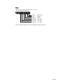
1.2 Features of Ethernet Communications
The Ethernet I/F board and the “Ethernet” function of the MOTOCOM32 transmit data at higher than
normal speeds.
●High speed transmission
In comparison with transmissions using RS232C, higher speed transmissions are possible with the
Ethernet.
When Ethernet is used
Ethernet
Personal computer
10 Mbps
Robot
controller
When RS232C is used
RS232C
Personal computer
9600 bps
Robot
controller
Fig 1.1
Transmission Speed
Note : The above transmission speed is the communication speed between network devices, not
including the time used for format check of transmitted data, etc.
●Transmissions between a multiple number of HOSTS
As N:N transmission is possible with an Ethernet cable, the following system configurations can
be prepared.
Note: Refer to paragraph 2.3 “Restrictions” with the following Configuration Examples.
【Configuration Example 1】
5/201
Since an Ethernet cable can be connected to a multiple number of network devices, the factory
operation state and alarm occurrences can be monitored from several places.
Monitoring
Monitoring
Factory
room A
room B
Ethernet
Personal
computer
Robot
Robot
Robot
Robot
Robot
controller controller controller controller controller
Fig 1.2
Personal
computer
Configuration Example 1
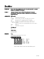
【Configuration Example 2】
By connecting the LANs of different factories with one Ethernet cable, transmission in each factory
can be executed simultaneously. The transmission between the robot controller and the personal
computer in factory A does not interfere with the transmission between the robot controller and the
personal computer in factory B. Transmission can also be done between factories. (In both cases,
the settings should be correct.)
LAN in A factory
Personal computer
LAN in B
factory
Ethernet
Personal
computer
Robot
controller
Robot
Robot
Robot
Robot
Robot
controller controller controller controller controller
Fig 1.3
Configuration Example 2
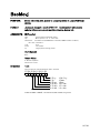
【Configuration Example 3】
With the Ethernet cables, the job on a personal computer can be executed on the robot controller by
installing a personal computer for each production line and transferring the job from the personal
computers to the robot controller. Then, by connecting one personal computer to the Ethernet cables
in all the production lines, monitoring of the state of all the production lines and data backup can be
executed.
Ethernet
A line
Ethernet
B line
C line
Ethernet
Robot Personal
Robot Personal Robot
Robot Personal
Robot
controller computer controller controller computer controller controller computer
Fig 1.4
Personal
computer
Configuration Example 3
6/201
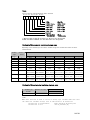
1.3 Hardware Requirements for MOTOCOM32
The MOTOCOM 32 operates with the configurations shown in Table 1.
Table 1
OS
CPU
Required Memory
Hardware Disk
Capacity for
Installation
Disk drive
Display
Mouse
Robot Controller
Transmission Cable
Hardware Lock Key
Hardware Requirements for MOTOCOM32
Microsoft Windows 95 /98 /NT4.0/2000/XP
Pentium, or pentium compatible processor
16 Mbyte or more
13 Mbyte or more
Hard disk and CD-ROM drive
Supported by MS-Windows
Supported by MS-Windows
NX100, YASNAC XRC, MRC, MRCⅡ, ERC, and ERCⅡ.
Ethernet cable or RS232C cable
Used under single user environment.
For details, refer to the following section “Hardware Lock.”
Notes 1: A personal computer and OS are not included with this software.
2: Use either an RS-232C cable or an Ethernet cable for transmission, depending on the data transmission
function specifications set in the robot controller manuals. Before starting this software, check the
hardware and software specifications of the robot controllers.
3: Ethernet transmission is not available for the YASNAC MRCⅡ/ ERC / ERCⅡ since they do not
support the Ethernet function.
For softwares and devices, refer to the robot controller Operator’s Manuals, Data Transmission
Operator’s Manual, Ethernet I/F Board Instructions, Manuals for MS-Windows, etc.
The cable connection for communications via RS232C is shown in Fig. 1.6.
Note : When using an Ethernet cable, the RS232C cable is not required.
IBM PC/AT
Robot Controller
(D-sub 25-pin male)
Personal Computer
(D-sub 9-pin female)
SD
2
2
RD
RD
3
3
SD
RS
4
5
SG
CS
5
7
RS
SG
7
8
CS
FG
1
7/201
Robot Controller
(D-sub 9-pin male)
Personal Computer
(D-sub 9-pin female)
RD
2
3
SD
SD
3
2
RD
SG
5
7
RS
RS
7
8
CS
CS
8
5
SG
FG
HOLDCASE
Fig. 1.5
RS232C Cable Connection
1.4 Hardware Lock Key
The software is protected by an hardware lock key. There are two different versions available (USB
and SUB-D type). The installation of the hardware lock key driver is included in the program
installation. In case of WindowsNT/2000/XP please log in with local administrative rights.
- SUB-D type
Attach the provided key to parallel port (printer port) of your pc. Make sure that it is not a 25pin
serial port. The key can also be attached to an existing key. If this makes problems change the
order of the keys.
- USB type
Please do not install the usb key before completing the program installation. Otherwise you may be
prompted for a driver disk. In this case cancel the operation and unplug the key again. Attach the
USB key to a free usb port of your pc. USB ports are only supported by Windows98SE and higher.
If there are problems starting the application check the proper installation of the key driver. Check
the Add/Remove Software section of the control panel for an entry named "Sentinel System
Driver...".
8/201
2. SETUP
2.1 Execution of Setup Program
Set up the MOTOCOM 32 in the following manner.
(1) Turn ON the power to the personal computer and the display.
(2) Start up Windows.
(3) Insert the High Speed JobExchanger installation CD-ROM into the CD-ROM drive.
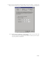
(4) Click the [Start] button in the task bar and select [Setting].
Programs] icon from [Control Panel].
Fig 2.1
Double-click the [Add/Remove
The [Add/Remove Programs Properties] display appears.
[Add/Remove Programs Properties] Display
(5) Click the [Install] button and follow the instructions in the display to set “setup.exe” of the CDROM drive.
The [Run Installation Program] dialog box appears.
11/201
Fig 2.2
[Run Installation Program] Dialog Box
(6) Clicking the [Finish] button calls up the setup program.
Follow the instructions in the proceeding
display.
(7) When the setup is completed, [High Speed JobExchanger], [Host Control], [Auto Job Changer],
[MOTOCOM 32 DLL Functions], [MOTOCOM 32 Help] and [YASNAC Help] are registered
under [MOTOCOM 32] folder that appears by clicking the [Start] button in the task bar to select
[Program] and then [Motoman].
Note: To re-install the MOTOCOM 32 for some reasons, select [MOTOCOM 32] in the [Add/Remove
Program Properties] Display shown in the Fig 2.1 and delete all the MOTOCOM32 application
files before starting re-installation.
2.2 Environmental Settings for Use of Ethernet
The following configurations are required for Ethernet transmissions.
for the RS232C communication.
These settings are not necessary
Refer to the “RS232C Condition” in 3.2.2 “Menu Structure.”
2.2.1 MOTOCOM 32 Application Settings
To communicate with the robot controller, set the IP address etc., as a transmission parameter.
12/201
2.2.2 Personal Computer Settings
Set the settings related to Ethernet transmissions, to the personal computer with the software installed.
■Hardware settings
Before using the MOTOCOM32, connect the Ethernet board to the personal computer and check if
the Ethernet board operates correctly.
For connection methods, refer to the manual for the Ethernet board used.
■Windows Network settings
To communicate via the Ethernet, set the settings related to the Windows network.
button in the task bar and select [Setting].
Click the [Start]
Double-click the “Network” icon from [Control Panel].
The [Select Network Component Type] Dialog box appears.
(The example below is based on Windows95.)
(1) Click the [Add] button. The [Select Network Component Type] dialog box appears.
(2) Select [Adapter] from the list and click the [Add] button to set the Ethernet board for adapter. Choose
the network adapter that is added to the personal computer as mentioned in “Hardware setting.”
Fig 2.3
Selecting Adapter
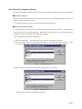
(3) Select the [Protocol] from the list and click the [Add] button, to set protocol.
Fig 2.4
Selecting Protocol
The [Select Network Protocol] dialog box appears.
13/201
(4) Select [Microsoft] as manufacturers and [TCP/IP] as Network Protocol and click the [OK] button.
Fig 2.5 [Select Network Protocol] Dialog Box
The [Network] dialog box appears.
(5) To set the IP address and subnet mask for the personal computer, select [TCP/IP] protocol from the
list and click the [Properties] button.
Fig 2.6 [Network] Dialog Box
The [TCP/IP Properties] dialog box appears.
14/201
(6) Input the value for the [IP address] and [Subnet Mask] of the personal computer. For details of the
settings of Gateway and DNS, refer to a Windows manual, to make proper settings for the application.
Fig 2.7
[TCP/IP Properties] Dialog Box
Note : The above values are examples only. When setting the IP address and subnet mask, input
the correct numbers as advised by the network manager.
An incorrect setting such as assigning the same IP address to different personal computers
may cause problems in communication.
15/201
2.2.3 Robot Controller Setting
■Hardware settings
To communicate using TCP/IP protocol, an Erthernet I/F board for NX100, YASNAC XRC/MRC is
required.
Insert the board, and set the IP address and subnet mask.
To setup the Ethernet I/F board, refer to the “NX100, YASNAC XRC/MRC Ethernet I/F Board
Instructions.”
■Parameter settings
To establish communication between the robot controller and the personal computer, set the
following parameters of the robot controller.
・Transmission protocol designation
RS000 = (*) Protocol designation for Std. port #1
RS001 = (*) Protocol designation for Std. port #2
(*) Settings for parameter RS000 / RS001 :
0 : Not used
1 : System reserved
2 : BSC LIKE protocol (used for data transmission)
3 : FC1 protocol
These parameters are used to designate the transmission protocol for Std port #1, port #2 or the
Ethernet board for the robot controller.
If the Ethernet communication function is not to be used,
RS000 and RS001 correspond to the Std port #1 and port #2 respectively as the above.
When the Ethernet communication function plus either Std port #1 or port #2 are used, parameters
according to this port number must be set.
Any other parameters can be used for Ethernet
communication.
To use the MOTOCOM 32, set RS000 or RS001 to the value “2.”
For example, if port #1 is already used for FC1 or FC2 and its parameter RS000 is set to the value
“3,” RS001 is required to be set to the value “2” to use the MOTOCOM 32.
Note : RS000/001 parameters cannot have the same setting.
Ethernet communication function only supports the BSC LIKE protocol.
Some parameters have to be set in “Maintenance mode” using the programming pendant.
16/201
・Customer options
I/O = Not used
Command mode = Used (This must be always set to “Used.”)
PP/PBOX (programming pendant / playback box)= Not used
・Ethernet
Ethernet = Used
IP ADDRESS = 192.168.10.10*
SUBNET MASK = 255.255.255.0*
DEFAULT GATEWAY = 192.168.10.1*
SERVER ADDRESS = 0.0.0.0*
*
The above values are examples only.
Input the suitable values according to your network
environment.
When the MOTOCOM 32 is used, there is no need to set the SERVER ADDRESS.
DCI or stand-alone function.
It is used for
For details, refer to the “NX100, YASNAC XRC/MRC Ethernet
I/F Board Instructions.”
2.2.4 Network Setting
To communicate with the robot controller using the MOTOCOM 32, the network must be set up
correctly.
For details on how to setup the network, refer to “NX100, YASNAC XRC/MRC Ethernet I/F Board
Instructions.”
2.3 Restrictions
When using the MOTOCOM 32, pay attention to the following restrictions.
2.3.1 NX100, YASNAC XRC/MRC and Personal Computer Restrictions
■ The port used for TCP/IP
The MOTOCOM 32 uses TCP/IP for the communication protocol.
To communicate in TCP/IP,
the service identification numbers called “Port No” are used internally, while MOTOCOM 32 uses
the port numbers from 10000 to 10008 for the data transmission.
When these numbers overlap with the numbers used for other network devices, correct
communication cannot be performed.
To use the MOTCOM 32, be sure in advance that any network device in the same network does not
use the above explained port numbers.
2.3.2 Personal Computer Restrictions
■Same file access
The same file in the personal computer cannot be accessed from different robot controllers
simultaneously.
17/201
Fig 2.8
Access to the Same File by Multiple Robot controllers not Possible
18/201
2.3.3 YASNAC Robot Controller Restrictions
■ Multiple personal computer access
BSC-Protocol
With the MOTOCOM32, one personal computer can communicate with one robot controller.
Simultaneous communication with a multiple number of personal computers is not possible.
(On the contrary, the simultaneous comunication between one personal computer and a multiple
number of robot controllers is possible.)
Fig.2.9 Access from a Multiple Personal Computers not Possible
EServer Protocol
By using EServer protocol multiple PC’s can communicate with one robot controller.
■CMOS batch storage
The BSC LIKE protocol and the FC1 protocol are available for the MOTOCOM 32 to
communicate with external devices.
transmission.
The MOTOCOM 32 uses the BSC LIKE protocol for
As the CMOS batch storage uses the FC1 protocol, CMOS batch storage is not
available in the MOTOCOM 32.
For CMOS batch storage, use the YASNAC FC1/FC2.
19/201
6.
CREATING
APPLICATION
A
TRANSMISSION
This paragraph describes how to create an application so that the user can easily create a transmission
application between the robot and the personal computer. This help explains how to create an
application using the sample program (MS-Windows application development tool with BASIC
language as the base “Visual Basic” and “Visual C++”) which employs a data transmission function
(MS-Windows DLL file type: file name: MOTOCOM32.DLL).
When “MOTOCOM32 Help” is opened, the following list of help topics appears.
Fig. 6.1
List of Help Topics to Explain How to Create a Transmission Application
Click a topic, “Outline,” “Creation procedure in Visual Basic,” “Creation method in Visual C++,” and
“Auto Job Changer software” to view information about that specific item. (After reading each
description, click the [Contents] button to return to the help contents display.)
20/201
6.1 Outline
This on-line Help describes how to create a transmission application using the 32-bit YASNAC
transmission library “MOTOCOM 32 DLL.”
This Help also describes how to create an application with Visual Basic and Visual C++. Other
languages can also be used.
6.2 Using Visual Basic
6.2.1 Preparation
To create a transmission application, the following systems must be installed in the personal computer
in advance.
① Microsoft Windows95/98/NT4.0/2000/XP*1
② Visual Basic Ver5.0 or more*2
*1 MS Windows 95/98/NT4.0/2000/XP is a registered trademark of Microsoft Corporation, U.S.A.
*2 Visual Basic is a registered trademark of Microsoft Corporation, U.S.A.
6.2.2 How to Create a transmission application
This paragraph explains a simple program, as an example, which sends/receives a job that was input to
the text box to/from the controller.
6.2.2.1 Creation of Code Module
In order to call up “Motocom32. DLL” from Visual Basic, declaration of the Motocom 32. DLL I/F
functions to be used is needed. The following two methods are available.
① Write the declaration of the DLL functions yourself.
② Use the definition file attached to the Motocom 32 package.
----------------------------------------------------------------------------------① Write the declaration of the DLL functions yourself.
----------------------------------------------------------------------------------Add the code module and write the following declaration in the declaration area.
Declare Function BscOpen Lib "MotoCom32" Alias "_BscOpen@8" _
(ByVal Path As String, ByVal mode As Integer) As Integer
Declare Function BscClose Lib "MotoCom32" Alias "_BscClose@4" _
(ByVal nCid As Integer) As Integer
Declare Function BscSetCom Lib "MotoCom32" Alias "_BscSetCom@24" _
(ByVal nCid As Integer, ByVal Port As Integer, ByVal Baud As Long, ByVal
Parity As Integer, ByVal clen As Integer, ByVal stp As Integer) As Integer
Declare Function BscConnect Lib "MotoCom32" Alias "_BscConnect@4" _
(ByVal nCid As Integer) As Integer
Declare Function BscDisConnect Lib "MotoCom32" Alias "_BscDisConnect@4" _
(ByVal nCid As Integer) As Integer
Declare Function BscDownLoad Lib "motocom32.dll" Alias "_BscDownLoad@8" _
(ByVal nCid As Integer, ByVal fName As String) As Integer
Declare Function BscUpLoad Lib "motocom32.dll" Alias "_BscUpLoad@8" _
(ByVal nCid As Integer, ByVal fName As String) As Integer
Define the followings as the parameters for BscOpen() to select the type of connection line.
Public Const PACKETCOM = (1)
Public Const PACKETETHERNET = (16)
21/201
----------------------------------------------------------------------------------② Use the definition file attached to the Motocom32 package.
----------------------------------------------------------------------------------The “Motocom32.DLL” package includes a “Motocom32.BAS” file that defines the DLL I/F
functions. Add this file to the Visual Basic project.
(1)
Copy the “Motocom32.BAS” file to the source directory of the application to be
created.
(2) Click “Project” and specify the “Motocom 32.BAS” from the “File” menu to add it
to the project.
Create a sub-module to open/close the following ports.
Function Ms_BscOpenComm(mode%)
Function Ms_BscCloseComm()
Select “Creation procedure in Visual Basic,” “Create code module,” and then “Function
Ms_BscOpencomm()” to select the data part (program list) of the above function. The selected
section will be highlighted. Use “Partial Copy” to copy this section to Ms_BscOpenComm ()
function. Repeat for Ms_BscCloseComm. and CmExit.
6.2.2.2 Creation of Form Module
Create the following module.
1) Form to be program display
On this form, create the following controls.
2) Text Box to input the job name (control name: “TxtJobName”, text name: 0.JBI”)
3) Send button (control name:”CmdDownLoad”, caption name: “Send”)
4) Receive button (control name: “CmUpLoad”, caption name: “Receive”)
5) Exit button (control name: “CmdExit”, caption name: “Exit”)
When the control is created, describe the event procedure for each button.
Sub CmdDownload_Click ()
Sub CmdUpLoad_Click ()
Sub CmdExit_Click ()
Select “Creation procedure in Visual Basic,” “Create from module,” and then “Sub
CmdDownload_Click()” to select the data part (program list) of the above function. The selected
section will be highlighted. Use “Partial Copy” to copy this section to Ms_BscOpenComm () function.
Repeat for CmdUpLoad and CmExit.
6.2.2.3 Creation and Execution of EXE File
Select “EXE file creation” from the Visual Basic file menu to create an execution enabled module. By
putting this module in the same directory as the job to be sent or received and executing it, the job can
be sent or received.
Note: The MOTOCOM installation directory contains data transmission functions (Windows DLL file
type, file name: Motocom32.DLL and Motolk.DLL, Motolkr.Dll). When executing an application,
copy the functions to the directory where the module to be executed is created. For transmission via
Ethernet, copy Vrp32.DLL, HxlSrv32.exe to the same directory as Motocom32.DLL.
22/201
Fig. 6.2
EXE File Execution Display
23/201
6.3 Using Visual C++
6.3.1 Preparation
To create a transmission application, the following systems must be installed in the personal computer
in advance.
③ Microsoft Windows95/98/NT4.0/2000/XP *1
④ Visual C++ Ver5.0 or more*2
*1 MS Windows 95/98/NT4.0/2000/XP is a registered trademark of Microsoft Corporation, U.S.A.
*2 Visual C++ is a registered trademark of, Microsoft Corporation U.S.A.
6.3.2 How to Create a transmission application
This paragraph explains a simple program, as an example, which sends/receives a job that was input to
the text box to/from the controller.
6.3.2.1 Creation of Skelton
Create a skelton using Visual C++ Ver.5.0 with the following procedure.
① Start up the Microsoft Development Studio and select “New” from the “File” menu to display
the “New” display. Then click “Project Work Space” and then the [OK] button.
② Select the “Project” tab and then “MFC AppWizard (exe).”
③ Enter the project name (in this example, input Test), and specify the folder where the project is
to be created. Then click the [OK] button.
④ Select “dialog base” as the type of the application to be created in “step 1,” and click the
[EXIT] button.
A source code to display a dialog box where only [OK] and [CANCEL] pushbuttons exist is
created.
6.3.2.2 Definition of DLL Call
① Include “motocom.h” attached to the MOTOCOM32 application using the dialog class source file
(TestDig.cpp). Also include the header file, “direct.h,” as the sample source as shown below.
#include "stdafx.h"
#include "Test.h"
#include "TestDlg.h"
#include <direct.h>
<------Add this line.
#include "motocom.h"
<------Add this line.
② Copy the “motocom32.lib” file, the “motocom.h” file and the data transmission function (Windows
DLL file type, file name: Motocom32.DLL and Motolk.DLL, Motolkr.Dll) to the directory where
the project exists.
③ Click the “Build” and then the “Setting” buttons, and open the “link” tab in the “Set Project” dialog
box. Specify the “motocom32.lib” file in the “Object/Library Module” setting column, and click
the [OK] button.
The MOTOCOM32 functions can be used in the file where “motocom.h” is included.
Note: The library file (file name: Motocom32.Lib) and the included file (file name: Motocom.h) are in
the MOTOCOM32 installation directory.
6.3.2.3 Editing with a Dialog Box
Edit the following with the created dialog box.
Open the IDD_TEST_DIALOG dialog box.
① Delete the [CANCEL] pushbutton which was created by default.
② Change the caption of the [OK] pushbutton to “Exit.”
24/201
③ Create an edit control to input the job name, and name the ID “IDC_JOBNAME.”
④ Create a pushbutton for sending, and name the caption “Send” and the ID “IDC_DOWNLOAD.”
⑤ Create a pushbutton for receiving, and name the caption “Receive” and the ID “IDC_UPLOAD.”
6.3.2.4 Addition of Functions and Variables
① Open the TestDLg.h file to add the following function declaration.
short TestOpenComm( int mode );
short TestCloseComm( short ncid );
② Create a function “CTestDlg::TestOpenComm” to open the communications port.
③ Create a function “CTestDlg::TestCloseComm” to close the communicatinos port.
④ Create a function “CTestDlg::OnDownload” for BN_CLICKED message in Class Wizard using the
[Send] pushbutton (IDC_DOWNLOAD).
⑤ Create a function “CTestDl::OnUpload” for BN_CLICKED message in Class Wizard using the
[Receive] pushbutton (IDC_UPLOAD).
⑥Add variable “m_jobname” in Class Wizard by Cedit type for inputting characters of the job name
edit control (IDC_JOBNAME).
After adding the functions, write the code in each function.
CTestDlg::TestOpenComm function
CTestDlg::TestCloseComm function
CTestDlg::OnDownload function
CTestDlg::OnUpload function
In the transmission application creation procedure Help, select “Creation procedure in Visual C++,”
“Addition of functions and variables,” and then “CTestDlg::TestOpenComm function” to select the data
part (program list) of the above function.
Use “Partial Copy” to copy this section to
CTestDlg::TestOpenComm() function. Repeat for CTestDlg::TestCloseComm, CTestDlg::OnDownload,
and CTestDlg::OnUpload.
25/201
6.3.2.5 Creation and Execution of EXE File
Execute “Build” in the Visual C++ Build menu to create a execution enabled module. By putting this
module in the same directory as the job to be sent or received and executing it, the job can be sent or
received.
Note: The MOTOCOM installation directory contains data transmission functions (Windows DLL file
type, file name: Motocom32.DLL and Motolk.DLL, Motolkr.Dll). When executing an application,
copy the functions to the directory where the module to be executed is created. For transmission via
Ethernet, copy Vrp32.DLL, HxlSrv32.exe to the same directory as Motocom32.DLL.
6.4 Explanation of Auto Job Changer Software Creation
Procedure
Procedure (procedure name: Sub DciOnline) to be called when “automatic operation” button is pressed
will be described as follows.
Since the Auto Job Changer software is created in Visual Basic, the following description is given in
the Visual Basic. However, Visual C++ or any other language can also be used.
Processing is divided into the following 5 major parts.
1) Opening of transmission port
[Function name: Ms_BscOpenComm( )]
2) Receiving of job number
[Function name: DciGetJobNo( )]
3) Preparation for sending job [Function name: GetJobnameByNo( ), JobCopy( )]
4) Sending of job
[Function name: DciLoadSave( )]
5) Closing of transmission port [Function name: Ms_BscCloseComm( )]
The following describes the list of each processing.
Sub DciOnline
Sub DciOnline (ProfileCom As String, CvtName As String, lst As Control, LogFile As String)
'input
ProfileCom
Communication profile character string ("COM1:96,E,8,1".etc.)
'
CvtName
Job name to be copied
'
Lst
List name for message output
'
LogFile
Log file name
'output
None
Dim nCid As Integer
Dim JobNo As Integer
Dim JobName As String
Dim rc As Integer
Dim Cycle As Long
Cycle = 0
'Get of communication handler
nCid = Ms_BscOpenComm() (mode) ’ mode=0 or 1
If nCid <> -1 Then
'Work No. receiving and job sending are repeated until Cancel button is pressed (F_QUIT flag
becomes true).
Do While Not F_QUIT
DispLogMsg lst, "***** Waiting for work No.*****", ""
'Receiving work No.
If Not DciGetJobNo(nCid, JobNo, lst, LogFile) Then Exit Do
DispLogMsg lst, "Work No. (" + Format$(JobNo) + ") reveived", LogFile
'Fetching job name corresponding to work No.
JobName = GetJobNameByNo(JobNo)
If JobName = "" Then
MsgBox "No corresponding job is registered."
Exit Do
26/201
End If
'Copying corresponding job to name for sending.
If Not JobCopy(JobName, CvtName) Then
MsgBox "Job copy disabled..(" + JobName + ")"
Exit Do
End If
DispLogMsg lst, JobName + "copied to " + CvtName + ".", LogFile
DispLogMsg lst, "***** Waiting for request for job transmission.*****", ""
'Sending job due to instruction from YASNAC.
If Not DciLoadSave(nCid, lst, LogFile) Then Exit Do
Cycle = Cycle + 1
DispLogMsg lst, "Job has been sent.(" + Format$(Cycle) + "Circulating).", LogFile
Loop
'No. of communication handlers.
rc = Ms_BscCloseComm(nCid)
If rc <> 0 Then
MsgBox "BscCloseComm terminates in fail." + "(" + Format$(rc) + ")."
End If
Else
MsgBox "Cannot open." + ProfileCom
End If
End Sub
Note:
Double underline indicates transmission functions belonging to the MOTOCOM32, single
underline indicates functions of which program lists are described below, and dotted underline
indicates the functions which are described below.
Function Ms_BscOpenComm ( mode% )
'mode: 0...RS-232C 1...Ethernet
Function Ms_BscOpenComm( mode% ) as Integer
Dim ncid As Integer
Dim rc As Integer
Dim IPAddrress As string
Ms_BscOpenComm = -1
if mode=0 then
‘Open the port.
ncid = BscOpen(CurDir$, 1)
If ncid < 0 Then GoTo Ms_BscOpenComm_Exit
‘Set serial communications parameters.
rc = BscSetCom(ncid, 1, 9600, 2, 8, 0)
else
‘Open the Ethernet line.
ncid = BscOpen(CurDir$, PACKETETHERNET)
If ncid < 0 Then GoTo Ms_BscOpenComm_Exit
'Set Ethernet communications parameters.
IPAddrress = "999.999.99.99" '<---Specify any IP address.
rc = BscSetEther( ncid , IPAddrress , 0, frmMain.hWnd )
end if
If rc <> 1 Then
27/201
rc = BscClose(ncid)
ncid = -1
GoTo Ms_BscOpenComm_Exit
End If
‘Connect communications line.
rc = BscConnect(ncid)
If rc <> 1 Then
rc = BscClose(ncid)
ncid = -1
GoTo Ms_BscOpenComm_Exit
End If
Ms_BscOpenComm_Exit:
Ms_BscOpenComm = ncid
End Function
This function opens the COM port or the Ethernet line. After the connection is finished, the
handle values are sent back as return values. The following operation for the Motocom32.DLL
is performed using these handle values.
Note:
Double underline indicates transmission functions belonging to the MOTOCOM32, single
underline indicates functions of which program lists are described below, and dotted underline
indicates the functions which are described below.
Function Ms_BscCloseComm
Function Ms_BscCloseComm(ncid as integer) as Integer
Dim rc As Integer
‘Cut the communications line.
rc = BscDisConnect(ncid)
‘Close the port.
rc = BscClose(ncid)
Ms_BscCloseComm = rc
End Sub
Note:
Double underline indicates transmission functions belonging to the MOTOCOM32, single
underline indicates functions of which program lists are described below, and dotted underline
indicates the functions which are described below.
Function DciGetJobNo
Function DciGetJobNo (nCid As Integer, JobNo As Integer, lst As Control, LogFile As String) As
Integer
'input
nCid
Communication handler
'
Lst
List name for message output
28/201
'
LogFile
Log file name
'output
JobNo
Received job No.
'return value TRUE
Completion of sending
'
FALSE
Cancel or error occurrence
Dim rc As Integer
Dim rc0 As Integer
'Declaring return value of BscDciGetPos.
ReDim axis6(5) As Double
Dim datatype As Integer
Dim RConf As Integer
rc = False
rc0 = -1
'Request for receiving is repeated until Cancel button is pressed (F_QUIT flag becomes true) or
work
No. is received.
Do While Not F_QUIT
rc0 = BscDCIGetPos(nCid, datatype, RConf, axis6(0))
If rc0 >= 0 Then Exit Do 'Work No. received.
Loop
If Not F_QUIT Then
If datatype <= 2 Then 'Only byte or integer type accepted.
'Received work No. set.
JobNo = axis6(0)
rc = True
Else
DispLogMsg lst, "Unexpected data type received. (" + Str$(datatype) + ")", LogFile
End If
Else
DispLogMsg lst, "Canceled.", ""
End If
DciGetJobNo = rc
End Function
Note:
Double underline indicates transmission functions belonging to the MOTOCOM-H, single
underline indicates functions of which program lists are described below, and dotted underline
indicates the functions which are described below.
Function DciLoadSave
Function DciLoadSave (nCid As Integer, lst As Control, LogFile As String) As Integer
'input
nCid
Communication handler
'
lst
List name for message output
'
LogFile
Log file name
'output
None
'return value TRUE
Completion of sending
'
FALSE
Cancel or error occurrence
Dim rc As Integer
Dim rc0 As Integer
rc = False
'Repeated until Cancel button is pressed (F_QUIT flag becomes true) or sending is completed.
Do While Not F_QUIT
rc0 = BscDCILoadSave(nCid, 1)
If rc0 > 0 Then 'Sending completed.
rc = True
Exit Do
ElseIf rc0 = 0 Then 'No request for receiving from YASNAC. Waiting for request for
receiving again
29/201
Else
'Job transmission error occurs.
MsgBox "Job transmission error occurs. (" + Format$(rc0) + ")"
Exit Do
End If
Loop
If F_QUIT = True Then
DispLogMsg lst, "Canceled.", ""
End If
DciLoadSave = rc
End Function
Note:
Double underline indicates transmission functions belonging to the MOTOCOM-H, single
underline indicates functions of which program lists are described below, and dotted underline
indicates the functions which are described below.
Other Functions
Function name
DispLogMsg()
GetJobNameByNo()
MsgBox()
JobCopy()
Contents
Outputs a message to the list box and log file.
Returns the number corresponding to the work number.
Displays a message in the dialog box and waits for the button to be pressed.
Copies a job to a specified file.
30/201
7. COMMUNICATION TRANSMISSION
When [MOTOCOM32. DLL function] is opened, the following list of help topics appears.
Fig. 7.1 List of Help Topics to Explain Transmission Functions
Clicking “File Data Transmission Function,” “Robot Control Function,” “DCI Function,” “I/O Read
and Write Function,” or “Other Functions,” the items related to the detailed contents are displayed.
(After reading each description, click the “Contents” button to return to the Help Contents Display.)
7.1 Outline
MOTOCOM32.DLL is a transmission library that controls the data transmission function of the NX100,
the YASNAC XRC, MRC, ERC, and ERCⅡ on a personal computer. This library is composed in the
form of Windows DLL (Dynamic Link Library).
Note:
MOTOCOM32.DLL is located below the MOTOCOM32 installation directory. When a
transmission application is created, copy this file to the same directory as the application.
MOTOCOM.H and MOTOCOM32.LIB files are provided in the MOTOCOM32 installation
directory. Use these files when a transmission application is created in C-language.
Transmission library has the following functions.
・File data transmission function
・Robot control function
・ DCI function
・ I/O signal read/write function
・Other functions
7.2 File Data Transmission Function
31/201
Loads and saves the files containing job, condition data, system information, etc.
The following functions are available.
BscDownload
BscUpload
BscDownLoadEx
BscUploadEx
32/201
BscDownLoad
FUNCTION:
Sends a specified file to the robot controller.
FORMAT:
_declspec( dllexport ) short APIENTRY BscDownLoad(short
nCid,char*fname);
ARGUMENTS:
IN(Transfer)
nCid
*fname
Communication handler ID number
File name to be sent
OUT(Return)
None
Return Value
0:Normal completion
Others:Transmission error
33/201
BscUpLoad
FUNCTION:
Receives a specified file from the robot controller.
FORMAT:
_declspec( dllexport ) short APIENTRY BscUpLoad(short nCid, char
*fname);
ARGUMENTS:
IN(Transfer)
nCid
*fname
Communication handler ID number
File name to be received
OUT(Return)
None
Return Value
0:Normal completion
Others:Receiving error
34/201
BscDownLoadEx
FUNCTION:
Sends a specified file to the robot controller. A directory where the sending
file exists can be specified.
FORMAT:
_declspec( dllexport ) short APIENTRY BscDownLoadEx(short nCid,char
*fname, char*path, BOOL nFlg);
ARGUMENTS:
IN(Transfer)
nCid
*fname
*path
nFlg
Communication handler ID number
File name to be sent
Diretory path of sending source data
TRUE
: Changes the directory temporarily and restores it at the end.
FALSE
: Changes the directory and completes the processing.
OUT(Return)
None
Return Value
0:Normal completion
Others:Transmission error
35/201
BscUpLoadEx
FUNCTION:
Receives a specified file from the robot controller.
the file is send to can be specified.
FORMAT:
_declspec( dllexport ) short APIENTRY BscUpLoadEx(short nCid,char
*fname, char*path, BOOL nFlg);
ARGUMENTS:
IN(Transfer)
nCid
*fname
*path
nFlg
The directory where
Communication handler ID number
File name to be received
Diretory path of sending source data
TRUE
: Changes the directory temporarily and restores it at the end.
FALSE
: Changes the directory and completes the processing.
OUT(Return)
None
Return Value
0:Normal completion
Others:Receiving error
36/201
7.3 Robot Control Function
Reads the robot status (current position, alarm, error, servo status, etc.) and controls the system (start, hold,
job call, etc.)
The following functions are available.
Status Read
BscFindFirst
BscFindFirstMaster
BscFindNext
BscFindNextMaster
BscGetCtrlGroup
BscGetCtrlGroupXrc
BscDownLoad
BscDownLoadEx
BscGetError
BscGetError2
BscGetFirstAlarm
BscGetFirstAlarmS
BscGetNextAlarm
BscGetNextAlarmS
BscGetStatus
BscGetUFrame
BscGetVarData
BscGetVarData2
BscHostGetVarData
BscHostGetVarDataM
BscIsAlarm
BscIsCtrlGroup
BscIsCtrlGroupXrc
BscIsCycle
BscIsError
BscIsErrorCode
BscIsHold
BscIsJobLine
BscIsJobName
BscIsJobStep
BscIsLoc
BscIsPlayMode
BscIsRemoteMode
BscIsRobotPos
BscIsServo
BscIsTaskInf
BscIsTaskInfXrc
BscIsTeachMode
BscJobWait
BscReadAlarmS
37/201
System Control
BscCancel
BscChangeTask
BscContinueJob
BscConvertJobP2R
BscConvertJobR2P
BscDeleteJob
BscHoldOff
BscHoldOn
BscHostPutVarData
BscHostPutVarDataM
BscImov
BscMDSP
BscMov
BscMovj
BscMovl
BscOPLock
BscOPUnLock
BscPMov
BscPMovj
BscPMovl
BscPutUFrame
BscPutVarData
BscPutVarData2
BscStartJob
BscSelectJob
BscSelectMode
BscSelLoopCycle
BscSelOneCycle
BscSelStepCycle
BscSetLineNumber
BscSetMasterJob
BscReset
BscSetCtrlGroup
BscSetCtrlGroupXrc
BscServoOff
BscServoOn
BscUpload
BscUploadEx
38/201
BscFindFirst
FUNCTION:
Reads the first job name from the all job list registered at the present
time.
FORMAT:
_declspec( dllexport ) short APIENTRY BscFindFirst(short
nCid,char*fname,short size);
ARGUMENTS:
IN(Transfer)
nCid
*fname
size
Communication handler ID number
First job name storage pointer
Job name storage area size
OUT(Return)
*fname
First job name storage pointer
Return Value
-1:No job
-2:Internal error (memory allocation error)
-3:Internal error (memory lock error)
-4:Other errors
0:Job found
39/201
BscFindFirstMaster
FUNCTION:
Reads the first job name from the job list that belongs to the master job.
FORMAT:
_declspec( dllexport ) short APIENTRY BscFindfirstMaster(short nCid,char
*fname,short size);
ARGUMENTS:
IN(Transfer)
nCid
*fname
size
Communication handler ID number
First job name storage pointer
Job name storage area size
OUT(Return)
*fname
First job name storage pointer
Return Value
-1:No job
-2:Internal error (memory allocation error)
-3:Internal error (memory lock error)
-4:Other errors
0:Job found
40/201
BscFindNext
FUNCTION:
Reads the next job name registered at the present time.
FORMAT:
_declspec( dllexport ) short APIENTRY BscFindNext(short nCid,char
*fname,short size);
ARGUMENTS:
IN(Transfer)
nCid
*fname
size
Communication handler ID number
N-th job name storage pointer
Job name storage area size
OUT(Return)
*fname
N-th job name storage pointer
Return Value
-1:No next job
0:Next job found
REMARKS:
Call Condition
The BscFindFirst function must be called up before executing this function.
41/201
BscFindNextMaster
FUNCTION:
Reads the next job name in the job list that belongs to the master job.
FORMAT:
_declspec( dllexport ) short APIENTRY BscFindNextMaster(short nCid,char
*fname,short size);
ARGUMENTS:
IN(Transfer)
nCid
*fname
size
Communication handler ID number
N-th job name storage pointer
Job name storage area size
OUT(Return)
*fname
N-th job name storage pointer
Return Value
-1:No next job
0:Next job found
REMARKS:
Call Condition
The BscFindFirstMaster function must be called up before executing this function.
42/201
BscGetCtrlGroup
FUNCTION:
Reads control group and task information.
FORMAT:
_declspec( dllexport ) short APIENTRY BscGetCtrlGroup(short nCid,short
*groupinf,short *taskinf);
ARGUMENTS:
IN(Transfer)
nCid
Communication handler ID number
*groupinf Control group information storage pointer
*taskinf
Task information storage pointer
OUT(Return)
*groupinf Control group information storage pointer
*taskinf
Task information storage pointer
Return Value
0:Normal completion
Others:Error codes
REMARKS:
Control Gourp Information
The control group information is represented by bit data in decimals.
D7 D6 D5 D4 D3 D2 D1 D0
D0:R1(Robot 1)
D1:R2(Robot 2)
D2:S1(Station 1)
D3:S2(Station 2)
D4:S3(Station 3)
D5:S4(Station 4)
D6:S5(Station 5)
D7:S6(Station 6)
Task Information
The task information is represented as follows.
0:Master task
1:Sub 1 task
2:Sub 2 task
“0” is returned if independent control is not allowed in the system.
NOTE
This function is effective only for transmission against the MRC (MRC transmission
function).
It cannot be used for transmission against the MRC (ERC compatible transmission function). Refer
to the BscGetCtrlGroupXrc for transmission against the NX100/XRC (NX100/XRC transmission
function).
43/201
BscGetCtrlGroupXrc
FUNCTION:
Reads control group and task information.
FORMAT:
_declspec( dllexport ) short APIENTRY BscGetCtrlGroupXrc(short
nCid,short *groupinf,short *stationinf, short *taskinf);
ARGUMENTS:
IN(Transfer)
nCid
Communication handler ID number
*groupinf Control group information storage pointer (robot axis)
*stationinf Control group information storage pointer (station axis)
*taskinf
Task information storage pointer
OUT(Return)
*groupinf Control group information storage pointer (robot axis)
*groupinf Control group information storage pointer (station axis)
*taskinf
Task information storage pointer
Return Value
0:Normal completion
Others:Error codes
REMARKS:
Control Group Information (Robot Axis)
The control group information is represented by bit data in decimals.
D7 D6 D5 D4 D3 D2 D1 D0
D0:
D1:
D2:
D3:
R1
R2
R3
R4
(Robot
(Robot
(Robot
(Robot
1)
2)
3)
4)
Control Group Information (Station Axis)
The control group information is represented by bit data in decimals.
D15 D14 D13 D12 D11 D10 D9 D8 D7 D6 D5 D4 D3 D2 D1 D0
D0: S1 (Station 1)
D1: S2 (Station 2)
D2: S3 (Station 3)
D3: S4 (Station 4)
D4: S5 (Station 5)
D5: S6 (Station 6)
D6: S7 (Station 7)
D7: S8 (Station 8)
D8: S9 (Station 9)
D9: S10 (Station 10)
D10: S11 (Station 11)
D11: S12 (Station 12)
* The control group information S7 to S12 are only for the NX100.
Task Information
The task information is represented as follows.
0: Master task
44/201
1:
2:
3:
4:
5:
6:
7:
Sub
Sub
Sub
Sub
Sub
Sub
Sub
1
2
3
4
5
6
7
task
task
task
task
task
task
task
“0” is returned if independent control is not allowed in the system.
NOTE
This function is effective for transmission against the NX100/XRC (NX100/XRC transmission
function). Refer to BscGetCtrlGroup for transmission against the MRC.
45/201
BscGetError
FUNCTION:
Reads an error code or alarm code.
FORMAT:
_declspec( dllexport ) short APIENTRY BscGetError(short nCid);
ARGUMENTS:
IN(Transfer)
nCid
Communication handler ID number
OUT(Return)
None
Return Value
-1:Acquisition Failure
0:No error
Others:Error codes
REMARKS:
Restrictions
This function is effective for transmission with the ERC. Refer to BscGetError2 for
transmission with the NX100, XRC or MRC.
46/201
BscGetError2
FUNCTION:
Reads an error code or alarm code.
FORMAT:
_declspec( dllexport ) short APIENTRY BscGetError2(short nCid);
ARGUMENTS:
IN(Transfer)
nCid
Communication handler ID number
OUT(Return)
None
Return Value
-1:Fetch failed
0:No error
Others:Error codes
47/201
BscGetFirstAlarm
FUNCTION:
Reads an alarm code and returns the alarm code and alarm data.
FORMAT:
_declspec( dllexport ) short APIENTRY BscGetFirstAlarm(short, nCid,short
*data)
ARGUMENTS:
IN(Transfer)
nCid
*data
Communication handler ID number
Alarm data storage pointer
OUT(Return)
*data
Alarm data storage pointer
Return Value
0:No alarm
Others:Alarm code numbers
REMARKS:
Call Condition
The BscGetError2 function must be called up before executing this function.
48/201
BscGetFirstAlarmS
FUNCTION:
Reads an alarm code and returns the alarm code, alarm data and alarm
message.
FORMAT:
_declspec( dllexport ) short APIENTRY BscGetFirstAlarm(short, nCid,short
*data,char *msg);
ARGUMENTS:
IN(Transfer)
nCid
*data
*msg
Communication handler ID number
Alarm data storage pointer
Alarm message storage pointer
OUT(Return)
*data
*msg
Alarm data storage pointer
Alarm message storage pointer
Return Value
0:No alarm
Others:Alarm code numbers
REMARKS:
Call Condition
The BscReadAlarmS function must be called up before executing this function.
Restrictions
This function is effective for transmission with the NX100 (NX100 communication function).
49/201
BscGetNextAlarm
FUNCTION:
Reads the next alarm code and alarm data.
FORMAT:
_declspec( dllexport )short APIENTRY BscGetNextAlarm(short nCid,short
*data);
ARGUMENTS:
IN(Transfer)
nCid
*data
Communication handler ID number
Alarm data storage pointer
OUT(Return)
*data
Alarm data storage pointer
Return Value
0:No alarm
Others:Alarm code numbers
REMARKS:
Call Condition
The BscGetFirstAlarm function must be called up before executing this function.
50/201
BscGetNextAlarmS
FUNCTION:
Reads the next alarm code, alarm data and alarm message.
FORMAT:
_declspec( dllexport )short APIENTRY BscGetNextAlarmS(short nCid,short
*data,char *msg);
ARGUMENTS:
IN(Transfer)
nCid
*data
*msg
Communication handler ID number
Alarm data storage pointer
Alarm message storage pointer
OUT(Return)
*data
*msg
Alarm data storage pointer
Alarm message storage pointer
Return Value
0:No alarm
Others:Alarm code numbers
REMARKS:
Call Condition
The BscGetFirstAlarmS function must be called up before executing this function.
Restrictions
This function is effective for transmission with the NX100 (NX100 communication function).
51/201
BscGetStatus
FUNCTION:
Reads the status information.
FORMAT:
_declspec( dllexport ) short APIENTRY BscGetStatus(short nCid,short
*d1,short *d2)
ARGUMENTS:
IN(Transfer)
nCid
*d1
*d2
Communication handler ID number
Data 1 storage pointer
Data 2 storage pointer
OUT(Return)
*d1
*d2
Data 1 storage pointer
Data 2 storage pointer
Return Value
-1:Fetch failed
Others:Normal completion
REMARKS:
Data 1
Data 1 are represented by bit data in decimals.
D7 D6 D5 D4 D3 D2 D1 D0
D0:Step
D4:Operation at safe speed
D1:1-cycle
D5:Teach *
D2:Auto operation
D6:Play *
D3:Operating
D7:Command remote *
*: Effective only for NX100, XRC and MRC.
Data 2
Data 2 are represented by bit data in decimals.
D7 D6 D5 D4 D3 D2 D1 D0
D0:Hold (NX100/XRC/MRC: Playback box hold, ERC:Panel hold)
D1:Hold (NX100/XRC/MRC: Programming pendant hold, ERC: T-BOX hold)
D2:Hold (External hold)
D3:Hold(Command hold)
D4:Alarm occurred
D5:Error occurred
D6:Servo ON
52/201
BscGetUFrame
FUNCTION:
Reads specified user frame data.
FORMAT:
_declspec( dllexport ) short APIENTRY BscGetUFrame(short nCid,char
*ufname,double *p);
ARGUMENTS:
IN(Transfer)
nCid
*ufname
*p
Communication handler ID number
Storage pointer of user coordinate name
User coordinate data storage pointer
OUT(Return)
*p
User coordinate data storage pointer
Return Value
-1:User coordinate name error
0:Normal completion
Others:Error codes
REMARKS:
User Coordinate Name
The following coordinate names correspond to the user coordinate numbers.
User Coordinate Name
Specified Name
User coordinate 1
User coordinate 2
User coordinate 3
User coordinate 4
User coordinate 5
User coordinate 6
User coordinate 7
User coordinate 8
User coordinate 9
User coordinate 10
User coordinate 11
User coordinate 12
UF1
UF2
UF3
UF4
UF5
UF6
UF7
UF8
UF9
UF10
UF11
UF12
User Coordinate Name
User
User
User
User
User
User
User
User
User
User
User
User
coordinate
coordinate
coordinate
coordinate
coordinate
coordinate
coordinate
coordinate
coordinate
coordinate
coordinate
coordinate
13
14
15
16
17
18
19
20
21
22
23
24
Specified
Name
UF13
UF14
UF15
UF16
UF17
UF18
UF19
UF20
UF21
UF22
UF23
UF24
*User coordinate numbers 9 to 24 are effective for NX100/XRC/MRC.
53/201
Variable type
Coordinate values of the user coordinate system specified with the user coordinate number are assigned to the
user coordinate data as follows.
Vari abl es Coordi nat e Syst em
P[ 0]
P[ 1]
P[ 2]
P[ 3]
P[ 4]
P[ 5]
P[ 6]
P[ 7]
P[ 8]
P[ 9]
P[ 10]
P[ 11]
P[ 12]
P[ 13]
P[ 14]
P[ 15]
P[ 16]
P[ 17]
P[ 18]
P[ 19]
P[ 20]
P[ 21]
P[ 22]
P[ 23]
P[ 24]
P[ 25]
P[ 26]
P[ 27]
ORG
Meani ng
X- axi s coordi nat e ( uni t : mm, ef f ect i ve down t o 3 deci mal pl aces)
Y- axi s coordi nat e ( uni t : mm, ef f ect i ve down t o 3 deci mal pl aces)
Z- axi s coordi nat e ( uni t : mm, ef f ect i ve down t o 3 deci mal pl aces)
Wri st angl e TX ( uni t : °, ef f ect i ve down t o 2 deci mal pl aces)
Wri st angl e TY ( uni t : °, ef f ect i ve down t o 2 deci mal pl aces)
Wri st angl e TZ ( uni t : °, ef f ect i ve down t o 2 deci mal pl aces)
Form
XX
XY
X- axi s coordi nat e ( uni t :
Y- axi s coordi nat e ( uni t :
Z- axi s coordi nat e ( uni t :
Wri st angl e TX ( uni t : °,
mm, ef f ect i ve down t o 3 deci mal pl aces)
mm, ef f ect i ve down t o 3 deci mal pl aces)
mm, ef f ect i ve down t o 3 deci mal pl aces)
ef f ect i ve down t o 2 deci mal pl aces)
Wri st angl e TY ( uni t : °, ef f ect i ve down t o 2 deci mal pl aces)
Wri st angl e TZ ( uni t : °, ef f ect i ve down t o 2 deci mal pl aces)
Form
X- axi s coordi nat e ( uni t : mm, ef f ect i ve down t o 3 deci mal pl aces)
Y- axi s coordi nat e ( uni t : mm, ef f ect i ve down t o 3 deci mal pl aces)
Z- axi s coordi nat e ( uni t : mm, ef f ect i ve down t o 3 deci mal pl aces)
Wri st angl e TX ( uni t : °, ef f ect i ve down t o 2 deci mal pl aces)
Wri st angl e TY ( uni t : °, ef f ect i ve down t o 2 deci mal pl aces)
Wri st angl e TZ ( uni t : °, ef f ect i ve down t o 2 deci mal pl aces)
Form
Tool number ( 0 t o 23)
7t h axi s pul se number ( mm f or t ravel i ng axi s)
8t h axi s pul se number ( mm f or t ravel i ng axi s)
9t h axi s pul se number ( mm f or t ravel i ng axi s)
10t h axi s pul se number
11t h axi s pul se number
12t h axi s pul se number
Form
The form data are represented by bit data in decimals.
D7 D6 D5 D4 D3 D2 D1 D0
0: Fl i p,
0: Up,
0: Front ,
0: R<180,
0: T<180,
0: S<180,
1: No- f l i p
1: Down
1: Rear
1: R>=180
1: T>=180
1: S>=180
* With the ERC or ERCⅡ, the data of D3, D4 and D5 are ignored.
54/201
BscGetVarData
FUNCTION:
Receives variables.
FORMAT:
_declspec( dllexport ) short APIENTRY BscGetVarData(short nCid,short
type,short varno,double *p);
ARGUMENTS:
IN(Transfer)
nCid
type
varno
*p
Communicaion handler ID number
Variable type
Variable number
Variable storage pointer
OUT(Return)
*p
Variable storage pointer
Return Value
0:Normal completion
Others:Error codes
REMARKS:
Variable Types
The variable types are represented as follows.
0:Byte type
1:Integer type
2:Double-precision type
3:Real type
4:Robot axis position type
5:Base axis position type
6:Station axis position type (pulse type only)
Details of Variables
Real
type
Robot axis
position type
Value
-
Doubleprecision
type
Value
-
Value
-
-
-
-
0
S-axis pulse
number
L-axis pulse
Byte
type
Integer
type
P[0]
P[1]
Value
-
P[2]
-
Base axis position
type
Station axis position
type
0
0
1st base axis pulse 1st station axis pulse
number
number
2nd base axis pulse
2nd station axis
55/201
P[3]
-
-
-
-
P[4]
-
-
-
-
P[5]
-
-
-
-
P[6]
-
-
-
-
P[7]
P[8]
P[9]
-
-
-
-
P[0]
P[1]
P[2]
P[3]
P[4]
P[5]
P[6]
P[7]
P[8]
P[9]
pulse
Robot axis position type
1
Coordinate type
X-axis coordinate (unit: mm)
Y-axis coordinate (unit: mm)
Z-axis coordinate (unit: mm)
Tx (unit: ゜)
Ty (unit: ゜)
Tz (unit: ゜)
Form
Tool number
number
U-axis pulse
number
R-axis pulse
number
B-axis pulse
number
T-axis pulse
number
Tool number
-
number
3rd base axis pulse
number
4th base axis pulse
number
5th base axis pulse
number
6th base axis pulse
number
Tool number
-
pulse number
3rd station axis
pulse number
4th station axis
pulse number
5th station axis
pulse number
6th station axis
pulse number
Tool number
-
Base axis position type
1
Coordinate type
1st base axis XYZ value (unit: mm)
2nd base axis XYZ value (unit: mm)
3rd base axis XYZ value (unit: mm)
4th base axis XYZ value (unit: mm)
5th base axis XYZ value (unit: mm)
6th base axis XYZ value (unit: mm)
Form
Tool number
The robot axis position and base axis position type variables include the
type and XYZ type, according to the first return value.
The station axis
position type variable contains the pulse type only.
See the following for details on the coordinate system types and form.
Coordinate Types
The following coordinate names correspond to the coordinate type data.
Coordinate type
0
1
2
3
4
5
6
7
8
9
10
11
12
Coordinate name
Base coordinate
Robot coordinate
User coordinate 1
User coordinate 2
User coordinate 3
User coordinate 4
User coordinate 5
User coordinate 6
User coordinate 7
User coordinate 8
User coordinate 9
User coordinate 10
User coordinate 11
Coordinate type
14
15
16
17
18
19
20
21
22
23
24
25
26
Coordinate name
User coordinate 13
User coordinate 14
User coordinate 15
User coordinate 16
User coordinate 17
User coordinate 18
User coordinate 19
User coordinate 20
User coordinate 21
User coordinate 22
User coordinate 23
User coordinate 24
Tool coordinate
56/201
13
User coordinate 12
27
Master tool coordinate
Form
The form data are represented by bit data in decimals.
D7 D6 D5 D4 D3 D2 D1 D0
0: Fl i p,
0: Up,
0: Front ,
0: R<180,
0: T<180,
0: S<180,
1: No- f l i p
1: Down
1: Rear
1: R>=180
1: T>=180
1: S>=180
* With the ERC or ERCⅡ, the data of D3, D4 and D5 are ignored.
NOTE
This function is effective only for transmission against the NX100/XRC/MRC (NX100/XRC/MRC
transmission function). It cannot be used for transmission against the NX100/XRC/MRC (ERC
compatible transmission function).
57/201
BscGetVarData2
FUNCTION:
Receives variables.( 7axes or more )
FORMAT:
_declspec( dllexport ) short APIENTRY BscGetVarData2(short nCid,short
type,short varno,double *p,short axisNum);
ARGUMENTS:
IN(Transfer)
nCid
type
varno
*p
axisNum
Communicaion handler ID number
Variable type
Variable number
Variable storage pointer
Axis
OUT(Return)
*p
Variable storage pointer
Return Value
0:Normal completion
Others:Error codes
REMARKS:
Variable Types
The variable types are represented as follows.
0:Byte type
1:Integer type
2:Double-precision type
3:Real type
4:Robot axis position type
5:Base axis position type
6:Station axis position type (pulse type only)
Details of Variables
P[0]
P[1]
Byte
type
Integer
type
Value
-
Value
-
Doubleprecision
type
Value
-
Real
type
Robot axis
position type
Base axis position
type
Station axis position
type
Value
-
0
S-axis pulse
number
0
0
1st base axis pulse 1st station axis pulse
number
number
58/201
P[2]
-
-
-
-
P[3]
-
-
-
-
P[4]
-
-
-
-
P[5]
-
-
-
-
P[6]
-
-
-
-
P[7]
-
-
-
-
P[8]
-
-
-
-
P[9]
-
-
-
-
P[0]
P[1]
P[2]
P[3]
P[4]
P[5]
P[6]
P[7]
P[8]
P[9]
pulse
Robot axis position type
1
Coordinate type
X-axis coordinate (unit: mm)
Y-axis coordinate (unit: mm)
Z-axis coordinate (unit: mm)
Tx (unit: ゜)
Ty (unit: ゜)
Tz (unit: ゜)
Form
Tool number
L-axis pulse
number
U-axis pulse
number
R-axis pulse
number
B-axis pulse
number
T-axis pulse
number
7axes pulse
number
8axes pulse
number
Tool number
2nd base axis pulse
number
3rd base axis pulse
number
4th base axis pulse
number
5th base axis pulse
number
6th base axis pulse
number
Tool number
2nd station axis
pulse number
3rd station axis
pulse number
4th station axis
pulse number
5th station axis
pulse number
6th station axis
pulse number
Tool number
-
-
-
-
Base axis position type
1
Coordinate type
1st base axis XYZ value (unit: mm)
2nd base axis XYZ value (unit: mm)
3rd base axis XYZ value (unit: mm)
4th base axis XYZ value (unit: mm)
5th base axis XYZ value (unit: mm)
6th base axis XYZ value (unit: mm)
Form
Tool number
The robot axis position and base axis position type variables include the
type and XYZ type, according to the first return value.
The station axis
position type variable contains the pulse type only.
See the following for details on the coordinate system types and form.
Coordinate Types
The following coordinate names correspond to the coordinate type data.
Coordinate type
0
1
2
3
4
5
6
7
8
9
10
Coordinate name
Base coordinate
Robot coordinate
User coordinate 1
User coordinate 2
User coordinate 3
User coordinate 4
User coordinate 5
User coordinate 6
User coordinate 7
User coordinate 8
User coordinate 9
Coordinate type
14
15
16
17
18
19
20
21
22
23
24
Coordinate name
User coordinate 13
User coordinate 14
User coordinate 15
User coordinate 16
User coordinate 17
User coordinate 18
User coordinate 19
User coordinate 20
User coordinate 21
User coordinate 22
User coordinate 23
59/201
11
12
13
User coordinate 10
User coordinate 11
User coordinate 12
25
26
27
User coordinate 24
Tool coordinate
Master tool coordinate
Form
The form data are represented by bit data in decimals.
D7 D6 D5 D4 D3 D2 D1 D0
0: Fl i p,
0: Up,
0: Front ,
0: R<180,
0: T<180,
0: S<180,
1: No- f l i p
1: Down
1: Rear
1: R>=180
1: T>=180
1: S>=180
NOTE
This function is effective only for transmission against the NX100/XRC. It cannot be used for
transmission against the NX100/XRC/MRC (ERC compatible transmission function).
60/201
BscHostGetVarData
FUNCTION:
Receives variables.
FORMAT:
_declspec( dllexport ) short APIENTRY BscHostGetVarData(short
nCid,short type,short varno,double *p,char *str);
ARGUMENTS:
IN(Transfer)
nCid
type
varno
*p
*str
Communication handler ID number
Variable type
Variable number
Head pointer to the numeric variable storage area
Head pointer to the character variable storage area
OUT(Return)
*p
Head pointer to the numeric variable storage area
Return Value
0:Normal completion
Others:Error codes
REMARKS:
Restrictions
This function is effective only for transmission with the NX100/XRC/MRC (NX100/XRC/MRC
transmission function). String variables can only be used with the NX100 ver3.0 or later.
Variable Types
The variable types are represented as follows.
0:Byte type
1:Integer type
2:Double-precision type
3:Real type
4:Robot axis position type
5:Base axis position type
6:Station axis position type (pulse type only)
7:String type
61/201
Content of the numeric variable storage area
Depending on the variable type, the numeric variable storage area contains the number of values
indicated below.
Variable
Type
Number
Data Type Number
(Pulse/
of
XYZ)
values
Content
0
1
2
3
4
4
5
Pulse
XYZ
Pulse
1
1
1
1
8
10
8
P[0]
Byte
Integer
Double
Real
0
1
0
5
6
XYZ
Pulse
10
8
1
0
Variable
Type
Number
Data Type Number
(Pulse/
of
XYZ)
values
0
1
2
3
4
4
5
Pulse
XYZ
Pulse
1
1
1
1
8
10
8
5
6
XYZ
Pulse
10
8
pulse
P[1]
P[2]
P[3]
P[4]
S-axis Pulses
Coordinate Type
Base Axis-1
Pulses
L-axis Pulses
X-axis (mm)
Base Axis-2
Pulses
U-axis Pulses
Y-axis (mm)
R-axis Pulses
Z-axis (mm)
Base Axis-3
Pulses
Base Axis-4
Pulses
Coordinate Type
X-axis (mm)
Y-axis (mm)
Z-axis (mm)
Station Axis-1 Station Axis-2 Station Axis-3 Station Axis-4
Pulses
Pulses
Pulses
Pulses
Content
P[5]
P[6]
P[7]
P[8]
P[9]
B-axis Pulses
Rx Angle(deg)
Base Axis-5
Pulses
Rx Angle(deg)
Station Axis-5
Pulses
T-axis Pulses
Ry Angle(deg)
Base Axis-6
Pulses
Ry Angle(deg)
Station Axis-6
Pulses
Tool Number
Rz Angle(deg)
-
-
Form
Tool Number
Form
Tool Number
Tool Number
Rz Angle(deg)
Tool Number
The robot axis position and base axis position type variables include the
type and XYZ type, according to the first return value. The station axis
position type variable contains the pulse type only.
See below for details on the coordinate system types and form.
Content of the character variable storage area
Variable Type
Number
Data Type
(Pulse/ XYZ)
Number of values
7
-
16
Content
str
String
NOTE:
When this function is used to receive a string type variable make sure that
the character variable storage area is allocated for 17 characters.
Declaration in Visual Basic:
Dim S_Variable As String *17
Declaration in C++:
char S_Variable[17]
Coordinate Types
62/201
The following coordinate names correspond to the coordinate type data.
Coordinate type
0
1
2
3
4
5
6
7
8
9
10
11
12
13
Coordinate name
Base coordinate
Robot coordinate
User coordinate 1
User coordinate 2
User coordinate 3
User coordinate 4
User coordinate 5
User coordinate 6
User coordinate 7
User coordinate 8
User coordinate 9
User coordinate 10
User coordinate 11
User coordinate 12
Coordinate type
14
15
16
17
18
19
20
21
22
23
24
25
26
27
Coordinate name
User coordinate 13
User coordinate 14
User coordinate 15
User coordinate 16
User coordinate 17
User coordinate 18
User coordinate 19
User coordinate 20
User coordinate 21
User coordinate 22
User coordinate 23
User coordinate 24
Tool coordinate
Master tool coordinate
Form
The form data are represented by bit data in decimals.
D7 D6 D5 D4 D3 D2 D1 D0
0:Flip,
0:Elbow A bove,
0:Front S ide
0:R<180,
0:T<180,
0:S<180,
R eserved
1:N o-Flip
1:Elbow U nder
1:B ack S ide
1:R>=180
1:T>=180
1:S>=180
0:P revious S tep
C onsideration
1:Form
C onsideration
* With the MRC or MRCⅡ, the data of D6 and D7 are disregarded.
63/201
BscHostGetVarDataM
FUNCTION:
Receives multiple variables at the same time.
FORMAT:
_declspec( dllexport ) short APIENTRY BscHostGetVarDataM(short
nCid,short type,short varno,short num, double *p);
ARGUMENTS:
IN(Transfer)
nCid
type
varno
num
*p
Communication handler ID number
Variable type
Variable number
Number of variables
Head pointer to the numeric variable storage area
OUT(Return)
*p
Head pointer to the numeric variable storage area
Return Value
0:Normal completion
Others:Error codes
REMARKS:
Restrictions
This function is effective only for transmission with the NX100 (NX100 transmission function).
Variable Types
The variable types are represented as follows.
0:Byte type
1:Integer type
2:Double-precision type
3:Real type
Variable Designation Method
The variable information transmitted is composed of the number of values (num) requested of the
specified variable type, beginning with the value of the specified variable number (varno) followed by
the values of subsequent variables.
64/201
BscIsAlarm
FUNCTION:
Reads alarm status.
FORMAT:
_declspec( dllexport ) short APIENTRY BscIsAlarm(short nCid);
ARGUMENTS:
IN(Transfer)
nCid
Communication handler ID number
OUT(Return)
None
Return Value
-1:Fetch failed
0:No alarm
1:Alarm
65/201
BscIsCtrlGroup
FUNCTION:
Reads control group information.
FORMAT:
ARGUMENTS:
_declspec( dllexport ) short APIENTRY BscIsCtrlGroup(short nCid);
IN(Transfer)
nCid
Communication handler ID number
OUT(Return)
None
Return Value
-1:Fetch failed
Others:Control group information
REMARKS:
Control Group Information
The control group information is represented by bit data in decimals.
D7 D6 D5 D4 D3 D2 D1 D0
D0:R1(Robot 1)
D1:R2(Robot 2)
D2:S1(Station 1)
D3:S2(Station 2)
D4:S3(Station 3)
D5:S4(Station 4)
D6:S5(Station 5)
D7:S6(Station 6)
NOTE
This function is effective only for transmission against MRC (MRC transmission function).
It
cannot be used for transmission against MRC (ERC compatible transmission function). Refer to
BscIsCtrlGroupXrc for transmission against NX100/XRC (NX100/XRC transmission function).
66/201
BscIsCtrlGroupXrc
FUNCTION:
Reads control group information.
FORMAT:
_declspec( dllexport )short APIENTRY BsclsCtrlGroupXrc (short nCid,short
*robtask, short *stattask);
ARGUMENTS:
IN(Transfer)
nCid
Communication handler ID number
*robtask
Control group information storage pointer (robot axis)
*stattask Control group information storage pointer (station axis)
OUT(Return)
*robtask
Control group information storage pointer (robot axis)
*stattask Control group information storage pointer (station axis)
Return Value
-1:Fetch failed
Others:Control group information
REMARKS:
Control Group Information (Robot Axis)
The control group information is represented by bit data in decimals.
D7 D6 D5 D4 D3 D2 D1 D0
D0:
D1:
D2:
D3:
(Robot
(Robot
(Robot
(Robot
1)
2)
3)
4)
Control Group Information (Station Axis)
The control group information is represented by bit data in decimals.
D15 D14 D13 D12 D11 D10 D9 D8 D7 D6 D5 D4 D3 D2 D1 D0
D0: S1 (Station 1)
D1: S2 (Station 2)
D2: S3 (Station 3)
D3: S4 (Station 4)
D4: S5 (Station 5)
D5: S6 (Station 6)
D6: S7 (Station 7)
D7: S8 (Station 8)
D8: S9 (Station 9)
D9: S10 (Station 10)
D10: S11 (Station 11)
D11: S12 (Station 12)
* The control group information S7 to S12 are only for the NX100.
NOTE
This function is effective only for transmission against NX100/XRC (NX100/XRC transmission
function).
Refer to BscIsCtrlGroup for transmission against MRC.
67/201
BscIsCycle
FUNCTION:
Reads playback mode information.
FORMAT:
ARGUMENTS:
_declspec( dllexport ) short APIENTRY BscIsCycle(short nCid);
IN(Transfer)
nCid
Communication handler ID number
OUT(Return)
None
Return Value
-1:Fetch failed
0:Step mode
1:1-cycle mode
2:Auto mode
68/201
BscIsError
FUNCTION:
Reads error status.
FORMAT:
_declspec( dllexport ) short APIENTRY BscIsError(short nCid);
ARGUMENTS:
IN(Transfer)
nCid
Communication handler ID number
OUT(Return)
None
Return Value
-1:Fetch failed
0:No error
1:Error found
69/201
BscIsHold
FUNCTION:
Reads hold status.
FORMAT:
ARGUMENTS:
_declspec( dllexport ) short APIENTRY BscIsHold(short nCid);
IN(Transfer)
nCid
Communication handler ID number
OUT(Return)
None
Return Value
-1:Fetch failed
0:Not held
Others:See below
REMARKS:
Hold Status
The hold status data are represented by bit data in decimals.
D7 D6 D5 D4 D3 D2 D1 D0
HOLD(Playback box hold (MRC),Panel hold(ERC)
HOLD(Programming pendant hold)
HOLD(External hold)
HOLD(Command hold)
70/201
BscIsJobLine
FUNCTION:
Reads the current job line number.
FORMAT:
_declspec( dllexport ) short APIENTRY BscIsJobLine(short nCid);
ARGUMENTS:
IN(Transfer)
nCid
Communication handler ID number
OUT(Return)
None
Return Value
-1:Fetch failed
Others:Line numbers
71/201
BscIsJobName
FUNCTION:
Reads the current job name.
FORMAT:
_declspec( dllexport ) short APIENTRY BscIsJobName(short nCid,char
*jobname,short size);
ARGUMENTS:
IN(Transfer)
nCid
*jobname
size
Communication handler ID number
Job name storage pointer
Job name storage area size
OUT(Return)
*jobname
Job name storage pointer
Return Value
-1:Fetch failed
0:Normal completion
72/201
BscIsJobStep
FUNCTION:
Reads the current job step number.
FORMAT:
_declspec( dllexport ) short APIENTRY BscIsJobStep(short nCid);
ARGUMENTS:
IN(Transfer)
nCid
Communication handler ID number
OUT(Return)
None
Return Value
-1:Fetch failed
Others:Step numbers
73/201
BscIsLoc
FUNCTION:
Reads the current robot position in pulse or XYZ frame system.
FORMAT:
_declspec( dllexport ) short APIENTRY BscIsLoc(short nCid,short
ispulse,short *rconf,double *p);
ARGUMENTS:
IN(Transfer)
nCid
ispulse
*rconf
*p
Communication handler ID number
0:Cartesian coordinate system; 1:Joint coordinate system
Form storage pointer
Current position storage pointer
OUT(Return)
*rconf
*p
Form storage pointer
Current position storage pointer
Return Value
-1:Fetch failed
0:Normal completion
REMARKS:
Form
The form data are represented by bit data in decimals.
D7 D6 D5 D4 D3 D2 D1 D0
0: Fl i p,
0: Up,
0: Front ,
0: R<180,
0: T<180,
0: S<180,
1: No- f l i p
1: Down
1: Rear
1: R>=180
1: T>=180
1: S>=180
* With the ERC or ERCⅡ, the data of D3, D4 and D5 are ignored.
74/201
Current Position
The current position data are as follows when the joint coordinate system or
system are specified.
P[0]
P[1]
P[2]
P[3]
P[4]
P[5]
P[6]
P[7]
P[8]
P[9]
P[10]
P[11]
Joint coordinate system
S-axis pulse number
L-axis pulse number
U-axis pulse number
R-axis pulse number
B-axis pulse number
T-axis pulse number
7th axis pulse number
8th axis pulse number
9th axis pulse number
10th axis pulse number
11th axis pulse number
12th axis pulse number
Cartesian
coordinate
Cartesian coordinate system
X-axis coordinate (unit: mm)
Y-axis coordinate (unit: mm)
Z-axis coordinate (unit: mm)
Wrist angle TX (unit: ゜)
Wrist angle TY (unit: ゜)
Wrist angle TZ (unit: ゜)
7th axis pulse number (mm for traveling axis)
8th axis pulse number (mm for traveling axis)
9th axis pulse number (mm for traveling axis)
10th axis pulse number
11th axis pulse number
12th axis pulse number
75/201
BscIsPlayMode
FUNCTION:
Reads the operation mode.
FORMAT:
_declspec( dllexport ) short APIENTRY BscIsPlayMode(short nCid);
ARGUMENTS:
IN(Transfer)
nCid
Communication handler ID number
OUT(Return)
None
Return Value
-1:Fetch failed
0:Not operating
1:Operating
2:Operating at safe speed
76/201
BscIsRemoteMode
FUNCTION:
Reads the command remote mode status.
FORMAT:
nCid);
ARGUMENTS:
_declspec( dllexport ) short APIENTRY BscIsRemoteMode(short
IN(Transfer)
nCid
Communication handler ID number
OUT(Return)
None
Return Value
-1:Fetch failed
0:Not command remote mode
1:Command remote mode
77/201
BscIsRobotPos
FUNCTION:
Reads the current robot position in a specified frame system.
existence of the external axis can also be specified.
FORMAT:
_declspec( dllexport ) short APIENTRY BscIsRobotPos(short nCid,char
*framename,int isex,short *rconf,short *toolno,double *p);
ARGUMENTS:
IN(Transfer)
nCid
*framename
isex
*rconf
*toolno
*p
The
Communication handler ID number
Coordinate name; BASE:Base coordinate system; ROBOT:Robot
coordinate system; UF1:User coordinate system1...
0:No external axis, 1:With external axis
Form storage pointer
Tool number storage pointer
Current position storage pointer
OUT(Return)
*rconf
*toolno
*p
Form storage pointer
Tool number storage pointer
Current position storage pointer
Return Value
-1:Fetch failed
0:Normal completion
REMARKS:
Form
The form data are represented by bit data in decimals.
D7 D6 D5 D4 D3 D2 D1 D0
0: Fl i p,
0: Up,
0: Front ,
0: R<180,
0: T<180,
1: No- f l i p
1: Down
1: Rear
1: R>=180
1: T>=180
* With the ERC or ERCⅡ, the data of D3 and D4 are ignored.
78/201
Current Position
The current position data are as follows when the joint coordinate system or Cartesian coordinate
system is specified.
Current position in the specified coordinate system
P[0]
X-axis coordinate system (unit: mm)
P[1]
Y-axis coordinate system (unit: mm)
P[2]
Z-axis coordinate system (unit: mm)
P[3]
Wrist angle TX (unit: ゜)
P[4]
Wrist angle TY (unit: ゜)
P[5]
Wrist angle TZ (unit: ゜)
P[6]
7th axis pulse number (mm for traveling axis)
P[7]
8th axis pulse number (mm for traveling axis)
P[8]
9th axis pulse number (mm for traveling axis)
P[9]
10th axis pulse number
P[10]
11th axis pulse number
P[11]
12th axis pulse number
79/201
BscIsServo
FUNCTION:
Reads the servo status.
FORMAT:
ARGUMENTS:
_declspec( dllexport ) short APIENTRY BscIsServo(short nCid);
IN(Transfer)
nCid
Communication handler ID number
OUT(Return)
None
Return Value
-1:Fetch failed
0:Servo OFF
1:Servo ON
80/201
BscIsTaskInf
FUNCTION:
Reads task information.
FORMAT:
ARGUMENTS
_declspec( dllexport ) short APIENTRY BscIsTaskInf(short nCid);
IN(Transfer)
nCid
Communication handler ID number
OUT(Return)
None
Return Value
-1:Fetch failed
Others:Task information
REMARKS:
Task Information
The task information is represented as follows.
0:Master task
1:Sub 1 task
2:Sub 2 task
“0” is returned when independent control is not allowed in the system.
NOTE
This function is effective only for transmission against the MRC (MRC transmission function).
It
cannot be used for transmission against the MRC (ERC compatible transmission function). Refer to
BscIsTaskInfXrc for transmission against the NX100/XRC (NX100/XRC transmission function).
81/201
BscIsTaskInfXrc
FUNCTION:
Reads task information.
FORMAT:
_declspec( dllexport ) short APIENTRY BscIcTaskInfXrc(short nCid)
ARGUMENTS
IN(Transfer)
nCid
Communication handler ID number
OUT(Return)
None
Return Value
-1:Fetch failed
Others:Error codes
REMARKS:
Task Information
The task information is represented as follows.
0:
1:
2:
3:
4:
5:
6:
7:
Master task
Sub 1 task
Sub 2 task
Sub 3 task
Sub 4 task
Sub 5 task
Sub 6 task
Sub 7 task
“0” is returned if independent control is not allowed in the system.
NOTE
This function is effective for transmission against the NX100/XRC (NX100/XRC transmission
function). Refer to BscIsTaskInf for transmission against the MRC.
82/201
BscIsTeachMode
FUNCTION:
Reads whether in the teach mode or play mode.
FORMAT:
_declspec( dllexport ) short APIENTRY BscIsTeachMode(short,nCid);
ARGUMENTS:
IN(Transfer)
nCid
Communication handler ID number
OUT(Return)
None
Return Value
-1:Fetch failed
0:Teach mode
1:Play mode
83/201
BscJobWait
FUNCTION:
Waits for job completion until the robot stops or specified time expires.
FORMAT:
_declspec( dllexport ) short APIENTRY BscJobWait(short nCid,short time);
ARGUMENTS:
IN(Transfer)
nCid
time
Communication handler ID number
Wait time(-1:Unlimited; 0 to 32767seconds)
OUT(Return)
None
Return Value
-2:Abnormal completion
-1:Operation incomplete
0:Operation completed
Others:Error codes
REMARKS:
Cause of Incomplete Operation
These causes are considered for imcomplete operation.
*The robot was stopped via teach pendant or by external hold.
*The robot was stopped by alarm.
*The robot was stopped by emergency stop.
*Time expired
84/201
BscReadAlarmS
FUNCTION:
Reads the error code, error data and error message.
FORMAT:
_declspec( dllexport ) short APIENTRY BscReadAlarmS(short, nCid,short
*data,char *msg);
ARGUMENTS:
IN(Transfer)
nCid
*data
*msg
Communication handler ID number
Error data storage pointer
Error message storage pointer
OUT(Return)
*data
*msg
Error data storage pointer
Error message storage pointer
Return Value
-1:Error code acquisition failure
0:No Error
Others:Error code numbers
REMARKS:
Restrictions
This function is effective for transmission with the NX100 (NX100 communication function).
85/201
BscCancel
FUNCTION:
Cancels an error.
FORMAT:
_declspec( dllexport ) short APIENTRY BscCancel(short nCid);
ARGUMENTS:
IN(Transfer)
nCid
Communication handler ID number
OUT(Return)
None
Return Value
0:Normal completion
Others: Error codes
86/201
BscChangeTask
FUNCTION:
Changes a task.
FORMAT:
_declspec( dllexport ) short APIENTRY BscChangeTask(short nCid,short
task);
ARGUMENTS:
IN(Transfer)
nCid
task
Communication handler ID number
Specified task number
OUT(Return)
None
Return Value
0:Normal completion
Others: Error codes
REMARKS:
Specified Task Number
The task number is represented as follows.
0:Master task
1:Subtask 1
2:Subtask 2
3:Subtask 3
4:Subtask 4
5:Subtask 5
6:Subtask 6
7:Subtask 7
* Specified task number 3 to 7 are only for the NX100 and XRC.
NOTE
This function is effective only for transmission against the NX100/XRC/MRC (NX100/XRC/MRC
transmission function). It cannot be used for transmission against the NX100/XRC/MRC (ERC
compatible transmission function).
When the power supply of robot controller is started up, a master task is selected as
an task to be controlled.
This function can not be used in a system where an
independent control is not allowed.
87/201
BscContinueJob
FUNCTION:
Starts job.(Execution starts from the current line of the current job.)
FORMAT:
_declspec( dllexport ) short APIENTRY BscContinueJob(short nCid);
ARGUMENTS:
IN(Transfer)
nCid
Communication handler ID number
OUT(Return)
None
Return Value
0:Normal completion
Others: Error codes
88/201
BscConvertJobP2R
FUNCTION:
Converts a pulse job to a relative job in a specified frame system.
FORMAT:
_declspec( dllexport ) short APIENTRY BscConvertJobP2R(short nCid,char
*name,char *framename);
ARGUMENTS:
IN(Transfer)
nCid
Communication handler ID number
*name
Job name storage pointer
*framename Coordinate name: BASE:Base coordinate: ROBOT:Robot coordinate:
UF1:User coordinate1...
OUT(Return)
None
Return Value
0:Normal completion
Others: Error codes
89/201
BscConvertJobR2P
FUNCTION:
Converts a relative job in a specified frame system to a pulse job.
FORMAT:
_declspec( dllexport ) short APIENTRY BscConvertJobR2P(short nCid,char
*name,short cv_type,char *var_no);
ARGUMENTS:
IN(Transfer)
nCid
*name
cv_type
var_no
Communication handler ID number
Job name storage pointer
Conversion method
Reference position variable number
OUT(Return)
None
Return Value
0:Normal completion
Others: Error codes
REMARKS:
Conversion Method
The conversion method is represented as follows.
0:Previous step regarded (B-axis sign constant)
1:Type regarded
2:Previous step regarded (Minimum R-axis movement)
NOTE
This function is effective only for transmission against the NX100/XRC/MRC (NX100/XRC/MRC
transmission functions.)
It cannot be used for transmission against the NX100/XRC/MRC (ERC
compatible transmission function).
90/201
BscDeleteJob
FUNCTION:
Deletes a job.
FORMAT:
_declspec( dllexport ) short APIENTRY BscDeleteJob(short nCid);
ARGUMENTS:
IN(Transfer)
nCid
Communication handler ID number
OUT(Return)
None
Return Value
0:Normal completion
1:Cannot delete
Others: Error codes
REMARKS:
Call Condition
The BscSelectJob function must be called up and the job name to be deleted must be specified
before executing this function.
91/201
BscHoldOn
FUNCTION:
Sets hold-ON.
FORMAT:
ARGUMENTS:
_declspec( dllexport ) short APIENTRY BscHoldOn(short nCid);
IN(Transfer)
nCid
Communication handler ID number
OUT(Return)
None
Return Value
0:Normal completion
Others: Error codes
92/201
BscHoldOff
FUNCTION:
Sets hold-OFF.
FORMAT:
_declspec( dllexport ) short APIENTRY BscHoldOff(short nCid);
ARGUMENTS:
IN(Transfer)
nCid
Communication handler ID number
OUT(Return)
None
Return Value
0:Normal completion
Others: Error codes
93/201
BscHostPutVarData
FUNCTION:
Sets variables.
FORMAT:
_declspec( dllexport ) short APIENTRY BscHostPutVarData(short
nCid,short type,short varno,double *p,char *str);
ARGUMENTS:
IN(Transfer)
nCid
type
varno
*p
*str
Communication handler ID number
Variable type
Variable number
Head pointer to the numeric variable storage area
Head pointer to the character variable storage area
OUT(Return)
None
Return Value
0:Normal completion
Others:Error codes
REMARKS:
Restrictions
This function is effective only for transmission with the NX100/XRC/MRC (NX100/XRC/MRC
transmission function). String variables can only be used with the NX100 ver3.0 or later.
Variable Types
The variable types are represented as follows.
0:Byte type
1:Integer type
2:Double-precision type
3:Real type
4:Robot axis position type
5:Base axis position type
6:Station axis position type (pulse type only)
7:String type
94/201
Content of the numeric variable storage area
Depending on the variable type, the numeric variable storage area contains the number of values
indicated below.
Variable
Type
Number
Data Type Number
(Pulse/
of
XYZ)
values
Content
0
1
2
3
4
4
5
Pulse
XYZ
Pulse
1
1
1
1
8
10
8
P[0]
Byte
Integer
Double
Real
0
1
0
5
6
XYZ
Pulse
10
8
1
0
Variable
Type
Number
Data Type Number
(Pulse/
of
XYZ)
values
0
1
2
3
4
4
5
Pulse
XYZ
Pulse
1
1
1
1
8
10
8
5
6
XYZ
Pulse
10
8
pulse
P[1]
P[2]
P[3]
P[4]
S-axis Pulses
Coordinate Type
Base Axis-1
Pulses
L-axis Pulses
X-axis (mm)
Base Axis-2
Pulses
U-axis Pulses
Y-axis (mm)
R-axis Pulses
Z-axis (mm)
Base Axis-3
Pulses
Base Axis-4
Pulses
Coordinate Type
X-axis (mm)
Y-axis (mm)
Z-axis (mm)
Station Axis-1 Station Axis-2 Station Axis-3 Station Axis-4
Pulses
Pulses
Pulses
Pulses
Content
P[5]
P[6]
P[7]
P[8]
P[9]
B-axis Pulses
Rx Angle(deg)
Base Axis-5
Pulses
Rx Angle(deg)
Station Axis-5
Pulses
T-axis Pulses
Ry Angle(deg)
Base Axis-6
Pulses
Ry Angle(deg)
Station Axis-6
Pulses
Tool Number
Rz Angle(deg)
-
-
Form
Tool Number
Form
Tool Number
Tool Number
Rz Angle(deg)
Tool Number
The robot axis position and base axis position type variables include the
type and XYZ type, according to the first return value. The station axis
position type variable contains the pulse type only.
See below for details on the coordinate system types and form.
Content of the character variable storage area
Variable Type
Number
Data Type
(Pulse/ XYZ)
Number of values
7
-
16
Content
str
String
NOTE:
When this function is used to receive a string type variable make sure that
the character variable storage area is allocated for 17 characters.
Declaration in Visual Basic:
Dim S_Variable As String *17
Declaration in C++:
char S_Variable[17]
95/201
Coordinate Types
The following coordinate names correspond to the coordinate type data.
Coordinate type
0
1
2
3
4
5
6
7
8
9
10
11
12
13
Coordinate name
Base coordinate
Robot coordinate
User coordinate 1
User coordinate 2
User coordinate 3
User coordinate 4
User coordinate 5
User coordinate 6
User coordinate 7
User coordinate 8
User coordinate 9
User coordinate 10
User coordinate 11
User coordinate 12
Coordinate type
14
15
16
17
18
19
20
21
22
23
24
25
26
27
Coordinate name
User coordinate 13
User coordinate 14
User coordinate 15
User coordinate 16
User coordinate 17
User coordinate 18
User coordinate 19
User coordinate 20
User coordinate 21
User coordinate 22
User coordinate 23
User coordinate 24
Tool coordinate
Master tool coordinate
Form
The form data are represented by bit data in decimals.
D7 D6 D5 D4 D3 D2 D1 D0
0:Flip,
0:Elbow A bove,
0:Front S ide
0:R<180,
0:T<180,
0:S<180,
R eserved
1:N o-Flip
1:Elbow U nder
1:B ack S ide
1:R>=180
1:T>=180
1:S>=180
0:P revious S tep
C onsideration
1:Form
C onsideration
* With the MRC or MRCⅡ, the data of D6 and D7 are disregarded.
96/201
BscHostPutVarDataM
FUNCTION:
Sets multiple variables at the same time.
FORMAT:
_declspec( dllexport ) short APIENTRY BscHostPutVarDataM(short
nCid,short type,short varno,short num, double *p);
ARGUMENTS:
IN(Transfer)
nCid
type
varno
num
*p
Communication handler ID number
Variable type
Variable number
Number of variables
Head pointer to the numeric variable storage area
OUT(Return)
None
Return Value
0:Normal completion
Others:Error codes
REMARKS:
Restrictions
This function is effective only for transmission with the NX100 (NX100 transmission function).
Variable Types
The variable types are represented as follows.
0:Byte type
1:Integer type
2:Double-precision type
3:Real type
Variable Designation Method
The variable information transmitted is composed of the number of values (num) requested of the
specified variable type, beginning with the value of the specified variable number (varno) followed by
the values of subsequent variables.
97/201
BscImov
FUNCTION:
Moves robot with linear motion form the current position for the
increment value in a specified frame system.
FORMAT:
_declspec( dllexport ) short APIENTRY BscImov(short nCid,char
*vtype,double spd,char *framename,short toolno,double *p)
ARGUMENTS:
IN(Transfer)
nCid
Communication handler ID number
*vtype
Move speed selection; V:Control point; VR:Position angular
spd
Move speed (0.1 to □□□□.□mm/s,0.1 to □□□.□°/s)
*framename Coordinate name; BASE:Base coordinate; ROBOT:Robot coordinate;
UF1:User coordinate1...
TOOL:Tool coordinate (Only for NX100/XRC/MRC)
toolno
Tool number
*p
Target position storage pointer
OUT(Return)
None
Return Value
0:Normal completion
Others: Error codes
REMARKS:
Target Position
The target position is represented as follows.
Target position in specified coordinate system
P[0]
X-axis coordinate system (unit: mm)
P[1]
Y-axis coordinate system (unit: mm)
P[2]
Z-axis coordinate system (unit: mm)
P[3]
Wrist angle TX (unit: ゜)
P[4]
Wrist angle TY (unit: ゜)
P[5]
Wrist angle TZ (unit: ゜)
P[6]
7th axis pulse number (mm for traveling axis)
P[7]
8th axis pulse number (mm for traveling axis)
P[8]
9th axis pulse number (mm for traveling axis)
P[9]
10th axis pulse number
P[10]
11th axis pulse number
P[11]
12th axis pulse number
* Set “0” for data P[7] to P[11] if the system has no external axis.
98/201
Form
The form data are represented by bit data in decimals.
D7 D6 D5 D4 D3 D2 D1 D0
0: Fl i p,
0: Up,
0: Front ,
0: R<180,
0: T<180,
0: S<180,
1: No- f l i p
1: Down
1: Rear
1: R>=180
1: T>=180
1: S>=180
* With the ERC or ERCⅡ, the data of D3, D4 and D5are ignored.
99/201
BscMDSP
FUNCTION:
Sends message data.
FORMAT:
*ptr);
ARGUMENTS:
_declspec( dllexport ) short APIENTRY BscMDSP(short nCid,char
IN(Transfer)
nCid
*ptr
Communication handler ID number
Message storage pointer
OUT(Return)
None
Return Value
0:Normal completion
Others: Error codes
REMARKS:
Number of message characters
The character string for a message is restricted as follows.
With NX100/XRC/MRC;
Character string with 30 characters maximum.
With ERC;
Character string with 28 characters maximum.
100/201
BscMov
FUNCTION:
Moves robot with specified motion from the current position to a target
position in a specified frame system.
FORMAT:
_declspec( dllexport ) short APIENTRY BscMov(short nCid,char
*movtype,char *vtype,double spd,char *framename,short rconf,short
toolno,double *p);
ARGUMENTS:
IN(Transfer)
nCid
*movtype
value)
*vtype
spd
*framename
UF1:User
rconf
toolno
*p
Communication handler ID number
Motion type; MOVJ:Joint; MOVL:Linear; IMOV:Linear (incremental
Move speed selection; V:Control point; VR:Position angular
Move speed (0.1 to □□□□.□mm/s,0.1 to □□□.□°/s)
Coordinate name; BASE:Base coordinate; ROBOT:Robot coordinate;
coordinate1...
TOOL:Tool coordinate (Only for NX100/XRC/MRC with motion type “IMOV.”)
Form
Tool number
Target position storage pointer
OUT(Return)
None
Return Value
0:Normal completion
Others: Error codes
REMARKS:
Form
The form data are represented by bit data in decimals.
D7 D6 D5 D4 D3 D2 D1 D0
0: Fl i p,
0: Up,
0: Front ,
0: R<180,
0: T<180,
0: S<180,
1: No- f l i p
1: Down
1: Rear
1: R>=180
1: T>=180
1: S>=180
* With the ERC or ERCⅡ, the data of D3, D4 and D5are ignored.
101/201
Target Position
The target position data are represented as follows.
Target position in the specified coordinate system
P[0]
X-axis coordinate system (unit: mm)
P[1]
Y-axis coordinate system (unit: mm)
P[2]
Z-axis coordinate system (unit: mm)
P[3]
Wrist angle TX (unit: ゜)
P[4]
Wrist angle TY (unit: ゜)
P[5]
Wrist angle TZ (unit: ゜)
P[6]
7th axis pulse number (mm for traveling axis)
P[7]
8th axis pulse number (mm for traveling axis)
P[8]
9th axis pulse number (mm for traveling axis)
P[9]
10th axis pulse number
P[10]
11th axis pulse number
P[11]
12th axis pulse number
*Set “0” for data P[7] to P[11] if the system has no external axis.
102/201
BscMovj
FUNCTION:
Moves robot with joint motion to a target position in a specified frame
system.
FORMAT:
_declspec( dllexport ) short APIENTRY BscMovj(short nCid,double
spd,char *framename,short rconf,short toolno, double *p);
ARGUMENTS:
IN(Transfer)
nCid
Communication handler ID number
spd
Move speed(0.01 to 100.0%)
*framename Coordinate name; BASE:Base coordinate; ROBOT:Robot coordinate;
UF1:User coordinate1...
rconf
Form
toolno
Tool number
*p
Target position storage pointer
OUT(Return)
None
Return Value
0:Normal completion
Others: Error codes
REMARKS:
Form
The form data are represented by bit data in decimals.
D7 D6 D5 D4 D3 D2 D1 D0
0: Fl i p,
0: Up,
0: Front ,
0: R<180,
0: T<180,
0: S<180,
1: No- f l i p
1: Down
1: Rear
1: R>=180
1: T>=180
1: S>=180
* With the ERC or ERCⅡ, the data of D3, D4 and D5 are ignored.
103/201
Target Position
The target positions are represented as follows.
P[0]
P[1]
P[2]
P[3]
P[4]
P[5]
P[6]
P[7]
P[8]
P[9]
P[10]
P[11]
Target position in the specified coordinate system
X-axis coordinate system (unit: mm)
Y-axis coordinate system (unit: mm)
Z-axis coordinate system (unit: mm)
Wrist angle TX (unit: ゜)
Wrist angle TY (unit: ゜)
Wrist angle TZ (unit: ゜)
7th axis pulse number (mm for traveling axis)
8th axis pulse number (mm for traveling axis)
9th axis pulse number (mm for traveling axis)
10th axis pulse number
11th axis pulse number
12th axis pulse number
*Set “0” for data P[7] to P[11] if the system has no external axis.
104/201
BscMovl
FUNCTION:
Moves robot with linear motion to a target position in a specified frame
system.
FORMAT:
_declspec( dllexport ) short APIENTRY BscMovl(short nCid,char
*vtype,double spd,char *framename,short rconf,short toolno,double *p);
ARGUMENTS:
IN(Transfer)
nCid
Communication handler ID number
*vtype
Move speed selection; V:Control point; VR:Position angular
spd
Move speed(0.1 to □□□□.□mm/s,0.1 to □□□.□°/s)
*framename Coordinate name; BASE:Base coordinate; ROBOT:Robot coordinate;
UF1:User coordinate1...
rconf
Form
toolno
Tool number
*p
Target position storage pointer
OUT(Return)
None
Return Value
0:Normal completion
Others: Error codes
REMARKS:
Form
The form data are represented by bit data in decimals.
D7 D6 D5 D4 D3 D2 D1 D0
0: Fl i p,
0: Up,
0: Front ,
0: R<180,
0: T<180,
0: S<180,
1: No- f l i p
1: Down
1: Rear
1: R>=180
1: T>=180
1: S>=180
* With ERC or ERCⅡ, the data of D3, D4, and D5 are ignored.
105/201
Target Position
The target positions are represented as follows.
P[0]
P[1]
P[2]
P[3]
P[4]
P[5]
P[6]
P[7]
P[8]
P[9]
P[10]
P[11]
Target position in the specified coordinate system
X-axis coordinate system (unit: mm)
Y-axis coordinate system (unit: mm)
Z-axis coordinate system (unit: mm)
Wrist angle TX (unit: ゜)
Wrist angle TY (unit: ゜)
Wrist angle TZ (unit: ゜)
7th axis pulse number (mm for traveling axis)
8th axis pulse number (mm for traveling axis)
9th axis pulse number (mm for traveling axis)
10th axis pulse number
11th axis pulse number
12th axis pulse number
*Set “0” for data P[7] to P[11] if the system has no external axis.
106/201
BscOPLock
FUNCTION:
Interlocks the robot.
FORMAT:
_declspec( dllexport ) short APIENTRY BscOPLock(short nCid);
ARGUMENTS:
IN(Transfer)
nCid
Communication handler ID number
OUT(Return)
None
Return Value
0:Normal completion
Others: Error codes
REMARKS:
Interlock Status
Once interlock is set, all but the following are interlocked.
With NX100/XRC
*Hold from the programming pendant
*Hold, emergency stop from the playback box
*Input signal other than I/O 404x, 405x and 409x (including external hold, external servo OFF)
Interlock cannot be accomplished when the programming pendant is in the editing
mode,
when file access is operating by other functions.
With MRC
*Hold from the programming pendant
*Hold, emergency stop from the playback box
*Input signal other than I/O 404x and 405x (including external hold, external servo
Interlock cannot be accomplished when the programming pendant is in the editing
when file access is operating by other functions.
OFF)
mode,
or
or
With ERC
*Start and hold buttons of panel operation
*Emergency stop button of panel operation
*Servo power ON button of panel operation
107/201
BscOPUnLock
FUNCTION:
Releases the robot interlocked status.
FORMAT:
ARGUMENTS:
_declspec( dllexport ) short APIENTRY BscOPUnLock(short nCid);
IN(Transfer)
nCid
Communication handler ID number
OUT(Return)
None
Return Value
0:Normal completion
Others: Error codes
108/201
BscPMov
FUNCTION:
Moves robot to a specified pulse position.
FORMAT:
_declspec( dllexport ) short APIENTRY BscPMov(short nCid,char
*movtype,char *vtype,double spd,short toolno,double *p);
ARGUMENTS:
IN(Transfer)
nCid
*movtype
*vtype
spd
toolno
*p
Communication handler ID number
Motion type; MOVJ:Joint; MOVL:Linear
Move speed selection; V:Control point; VR:Position angular
Move speed(0.1 to □□□□.□mm/s,0.1 to □□□.□°/s)
Tool number
Target position storage pointer
OUT(Return)
None
Return Value
0:Normal completion
Others: Error codes
REMARKS:
Target Position
The target position data are represented as follows.
Target position in units of pulses
P[0]
S-axis pulse number
P[1]
L-axis pulse number
P[2]
U-axis pulse number
P[3]
R-axis pulse number
P[4]
B-axis pulse number
P[5]
T-axis pulse number
P[6]
7th axis pulse number
P[7]
8th axis pulse number
P[8]
9th axis pulse number
P[9]
10th axis pulse number
P[10]
11th axis pulse number
P[11]
12th axis pulse number
*Set “0” for data P[7] to P[11] if the system has no external axis.
109/201
BscPMovj
FUNCTION:
Moves robot to a specified pulse position with joint motion.
FORMAT:
_declspec( dllexport ) short APIENTRY BscPMovj(short nCid,double
sped,short toolno,double *p);
ARGUMENTS:
IN(Transfer)
nCid
spd
toolno
*p
Communication handler ID number
Move speed(0.1 to □□□□.□mm/s,0.1 to □□□.□°/s)
Tool number
Target position storage pointer
OUT(Return)
None
Return Value
0:Normal completion
Others: Error codes
REMARKS:
Target Position
The target position data are represented as follows.
Target position in units of pulses
P[0]
S-axis pulse number
P[1]
L-axis pulse number
P[2]
U-axis pulse number
P[3]
R-axis pulse number
P[4]
B-axis pulse number
P[5]
T-axis pulse number
P[6]
7th axis pulse number
P[7]
8th axis pulse number
P[8]
9th axis pulse number
P[9]
10th axis pulse number
P[10]
11th axis pulse number
P[11]
12th axis pulse number
*Set “0” for data P[7] to P[11] if the system has no external axis.
110/201
BscPMovl
FUNCTION:
Moves robot to a specified pulse position with linear motion.
FORMAT:
_declspec( dllexport ) short APIENTRY BscPMovl(short nCid,char
*vtype,double spd,short toolno,double *p);
ARGUMENTS:
IN(Transfer)
nCid
*vtype
spd
toolno
*p
Communication handler ID number
Move speed selection; V:Control point; VR:Position angular
Move speed(0.1 to □□□□.□mm/s,0.1 to □□□.□°/s)
Tool number
Target position storage pointer
OUT(Return)
None
Return Value
0:Normal completion
Others: Error codes
REMARKS:
Target Position
The target position data are represented as follows.
Target position in units of pulses
P[0]
S-axis pulse number
P[1]
L-axis pulse number
P[2]
U-axis pulse number
P[3]
R-axis pulse number
P[4]
B-axis pulse number
P[5]
T-axis pulse number
P[6]
7th axis pulse number
P[7]
8th axis pulse number
P[8]
9th axis pulse number
P[9]
10th axis pulse number
P[10]
11th axis pulse number
P[11]
12th axis pulse number
*Set “0” for data P[7] to P[11] if the system has no external axis.
111/201
BscPutUFrame
FUNCTION:
Sets a specified user frame data.
FORMAT:
_declspec( dllexport ) short APIENTRY BscPutUFrame(shortnCid,char
*ufname,double *p);
ARGUMENTS:
IN(Transfer)
nCid
*ufname
*p
Communication handler ID number
Storage pointer of the user coordinate name to be written in
User coordinate data storage pointer
OUT(Return)
None
Return Value
0:Normal completion
Others: Error codes
REMARKS:
User Coordinate Name
The following coordinate names correspond to the user coordinate numbers.
User Coordinate Name
Specified Name
User Coordinate Name
User coordinate 1
UF1
User coordinate 13
User coordinate 2
UF2
User coordinate 14
User coordinate 3
UF3
User coordinate 15
User coordinate 4
UF4
User coordinate 16
User coordinate 5
UF5
User coordinate 17
User coordinate 6
UF6
User coordinate 18
User coordinate 7
UF7
User coordinate 19
User coordinate 8
UF8
User coordinate 20
User coordinate 9
UF9
User coordinate 21
User coordinate 10
UF10
User coordinate 22
User coordinate 11
UF11
User coordinate 23
User coordinate 12
UF12
User coordinate 24
Specified Name
UF13
UF14
UF15
UF16
UF17
UF18
UF19
UF20
UF21
UF22
UF23
UF24
* User coordinate numbers 9 to 24 are effective only for NX100/XRC/MRC.
Variable type
Coordinate values of the user coordinate system specified with the user coordinate number are assigned to the
user coordinate data as follows.
112/201
Vari abl es Coordi nat e Syst em
P[ 0]
P[ 1]
P[ 2]
P[ 3]
P[ 4]
P[ 5]
P[ 6]
P[ 7]
P[ 8]
P[ 9]
P[ 10]
P[ 11]
P[ 12]
P[ 13]
P[ 14]
P[ 15]
P[ 16]
P[ 17]
P[ 18]
P[ 19]
P[ 20]
P[ 21]
P[ 22]
P[ 23]
P[ 24]
P[ 25]
P[ 26]
P[ 27]
ORG
Meani ng
X- axi s coordi nat e ( uni t : mm, ef f ect i ve down t o 3 deci mal pl aces)
Y- axi s coordi nat e ( uni t : mm, ef f ect i ve down t o 3 deci mal pl aces)
Z- axi s coordi nat e ( uni t : mm, ef f ect i ve down t o 3 deci mal pl aces)
Wri st angl e TX ( uni t : °, ef f ect i ve down t o 2 deci mal pl aces)
Wri st angl e TY ( uni t : °, ef f ect i ve down t o 2 deci mal pl aces)
Wri st angl e TZ ( uni t : °, ef f ect i ve down t o 2 deci mal pl aces)
Form
XX
XY
X- axi s coordi nat e ( uni t :
Y- axi s coordi nat e ( uni t :
Z- axi s coordi nat e ( uni t :
Wri st angl e TX ( uni t : °,
mm, ef f ect i ve down t o 3 deci mal pl aces)
mm, ef f ect i ve down t o 3 deci mal pl aces)
mm, ef f ect i ve down t o 3 deci mal pl aces)
ef f ect i ve down t o 2 deci mal pl aces)
Wri st angl e TY ( uni t : °, ef f ect i ve down t o 2 deci mal pl aces)
Wri st angl e TZ ( uni t : °, ef f ect i ve down t o 2 deci mal pl aces)
Form
X- axi s coordi nat e ( uni t : mm, ef f ect i ve down t o 3 deci mal pl aces)
Y- axi s coordi nat e ( uni t : mm, ef f ect i ve down t o 3 deci mal pl aces)
Z- axi s coordi nat e ( uni t : mm, ef f ect i ve down t o 3 deci mal pl aces)
Wri st angl e TX ( uni t : °, ef f ect i ve down t o 2 deci mal pl aces)
Wri st angl e TY ( uni t : °, ef f ect i ve down t o 2 deci mal pl aces)
Wri st angl e TZ ( uni t : °, ef f ect i ve down t o 2 deci mal pl aces)
Form
Tool number ( 0 t o 23)
7t h axi s pul se number ( mm f or t ravel i ng axi s)
8t h axi s pul se number ( mm f or t ravel i ng axi s)
9t h axi s pul se number ( mm f or t ravel i ng axi s)
10t h axi s pul se number
11t h axi s pul se number
12t h axi s pul se number
Form
The form data are represented by bit data in decimals.
D7 D6 D5 D4 D3 D2 D1 D0
0: Fl i p,
0: Up,
0: Front ,
0: R<180,
0: T<180,
0: S<180,
1: No- f l i p
1: Down
1: Rear
1: R>=180
1: T>=180
1: S>=180
* With the ERC or ERCⅡ, the data of D3, D4 and D5 are ignored.
113/201
BscPutVarData
FUNCTION:
Sets variable data.
FORMAT:
_declspec( dllexport) short APIENTRY BscPutVarData(short nCid,short
type,short varno,double *p);
ARGUMENTS:
IN(Transfer)
nCid
type
varno
*p
Communication handler ID number
Variable type
Variable number
Variable storage pointer
OUT(Return)
None
Return Value
0:Normal completion
Others: Error codes
REMARKS:
Variable Types
The variable types are represented as follows.
0:Byte type
1:Integer type
2:Double-precision type
3:Real type
4:Robot axis position type
5:Base axis position type
6:Station axis position type (pulse type only)
Details of Variables
Real
type
Robot axis
position type
Base axis position
type
Value
-
Doubleprecision
type
Value
-
Value
-
-
-
-
0
S-axis pulse
number
L-axis pulse
number
0
0
1st base axis pulse 1st station axis pulse
number
number
2nd base axis pulse
2nd station axis
number
pulse number
Byte
type
Integer
type
P[0]
P[1]
Value
-
P[2]
-
Station axis position
type
114/201
P[3]
-
-
-
-
P[4]
-
-
-
-
P[5]
-
-
-
-
P[6]
-
-
-
-
P[7]
P[8]
P[9]
-
-
-
-
P[0]
P[1]
P[2]
P[3]
P[4]
P[5]
P[6]
P[7]
P[8]
P[9]
pulse
Robot axis position type
1
Coordinate type
X-axis coordinate (unit: mm)
Y-axis coordinate (unit: mm)
Z-axis coordinate (unit: mm)
Tx (unit: ゜)
Ty (unit: ゜)
Tz (unit: ゜)
Form
Tool number
U-axis pulse
number
R-axis pulse
number
B-axis pulse
number
T-axis pulse
number
Tool number
-
3rd base axis pulse
number
4th base axis pulse
number
5th base axis pulse
number
6th base axis pulse
number
Tool number
-
3rd station axis
pulse number
4th station axis
pulse number
5th station axis
pulse number
6th station axis
pulse number
Tool number
-
Base axis position type
1
Coordinate type
1st base axis XYZ value (unit: mm)
2nd base axis XYZ value (unit: mm)
3rd base axis XYZ value (unit: mm)
4th base axis XYZ value (unit: mm)
5th base axis XYZ value (unit: mm)
6th base axis XYZ value (unit: mm)
Form
Tool number
The robot axis position and base axis position type variables include the
type and XYZ type, according to the first return value.
The station axis
position type variable contains the pulse type only.
See the following for details on the coordinate system types and form.
Coordinate Types
The following coordinate names correspond to the coordinate type data.
Coordinate type
0
1
2
3
4
5
6
7
8
9
10
11
Coordinate name
Base coordinate
Robot coordinate
User coordinate 1
User coordinate 2
User coordinate 3
User coordinate 4
User coordinate 5
User coordinate 6
User coordinate 7
User coordinate 8
User coordinate 9
User coordinate 10
Coordinate type
14
15
16
17
18
19
20
21
22
23
24
25
Coordinate name
User coordinate 13
User coordinate 14
User coordinate 15
User coordinate 16
User coordinate 17
User coordinate 18
User coordinate 19
User coordinate 20
User coordinate 21
User coordinate 22
User coordinate 23
User coordinate 24
115/201
12
13
User coordinate 11
User coordinate 12
26
27
Tool coordinate
Master tool coordinate
Form
The form data are represented by bit data in decimals.
D7 D6 D5 D4 D3 D2 D1 D0
0: Fl i p,
0: Up,
0: Front ,
0: R<180,
0: T<180,
0: S<180,
1: No- f l i p
1: Down
1: Rear
1: R>=180
1: T>=180
1: S>=180
* With the ERC or ERCⅡ, the data of D3, D4, and D5 are ignored.
NOTE
This function is effective only for transmission against the NX100/XRC/MRC (NX100/XRC/MRC
transmission functions). It cannot be used for transmission against the NX100/XRC/MRC (ERC
compatible transmission function).
116/201
BscPutVarData2
FUNCTION:
Sets variable data. ( 7axes or more )
FORMAT:
_declspec( dllexport) short APIENTRY BscPutVarData2(short nCid,short
type,short varno,double *p);
ARGUMENTS:
IN(Transfer)
nCid
type
varno
*p
Communication handler ID number
Variable type
Variable number
Variable storage pointer
OUT(Return)
None
Return Value
0:Normal completion
Others: Error codes
REMARKS:
Variable Types
The variable types are represented as follows.
0:Byte type
1:Integer type
2:Double-precision type
3:Real type
4:Robot axis position type
5:Base axis position type
6:Station axis position type (pulse type only)
Details of Variables
Real
type
Robot axis
position type
Base axis position
type
Value
-
Doubleprecision
type
Value
-
Value
-
-
-
-
0
S-axis pulse
number
L-axis pulse
number
0
0
1st base axis pulse 1st station axis pulse
number
number
2nd base axis pulse
2nd station axis
number
pulse number
Byte
type
Integer
type
P[0]
P[1]
Value
-
P[2]
-
Station axis position
type
117/201
P[3]
-
-
-
-
P[4]
-
-
-
-
P[5]
-
-
-
-
P[6]
-
-
-
-
P[7]
-
-
-
-
P[8]
-
-
-
-
P[9]
-
-
-
-
P[0]
P[1]
P[2]
P[3]
P[4]
P[5]
P[6]
P[7]
P[8]
P[9]
pulse
Robot axis position type
1
Coordinate type
X-axis coordinate (unit: mm)
Y-axis coordinate (unit: mm)
Z-axis coordinate (unit: mm)
Tx (unit: ゜)
Ty (unit: ゜)
Tz (unit: ゜)
Form
Tool number
U-axis pulse
number
R-axis pulse
number
B-axis pulse
number
T-axis pulse
number
7axes pulse
number
8axes pulse
number
Tool number
3rd base axis pulse
number
4th base axis pulse
number
5th base axis pulse
number
6th base axis pulse
number
Tool number
3rd station axis
pulse number
4th station axis
pulse number
5th station axis
pulse number
6th station axis
pulse number
Tool number
-
-
-
-
Base axis position type
1
Coordinate type
1st base axis XYZ value (unit: mm)
2nd base axis XYZ value (unit: mm)
3rd base axis XYZ value (unit: mm)
4th base axis XYZ value (unit: mm)
5th base axis XYZ value (unit: mm)
6th base axis XYZ value (unit: mm)
Form
Tool number
The robot axis position and base axis position type variables include the
type and XYZ type, according to the first return value.
The station axis
position type variable contains the pulse type only.
See the following for details on the coordinate system types and form.
Coordinate Types
The following coordinate names correspond to the coordinate type data.
Coordinate type
0
1
2
3
4
5
6
7
8
9
Coordinate name
Base coordinate
Robot coordinate
User coordinate 1
User coordinate 2
User coordinate 3
User coordinate 4
User coordinate 5
User coordinate 6
User coordinate 7
User coordinate 8
Coordinate type
14
15
16
17
18
19
20
21
22
23
Coordinate name
User coordinate 13
User coordinate 14
User coordinate 15
User coordinate 16
User coordinate 17
User coordinate 18
User coordinate 19
User coordinate 20
User coordinate 21
User coordinate 22
118/201
10
11
12
13
User coordinate 9
User coordinate 10
User coordinate 11
User coordinate 12
24
25
26
27
User coordinate 23
User coordinate 24
Tool coordinate
Master tool coordinate
Form
The form data are represented by bit data in decimals.
D7 D6 D5 D4 D3 D2 D1 D0
0: Fl i p,
0: Up,
0: Front ,
0: R<180,
0: T<180,
0: S<180,
1: No- f l i p
1: Down
1: Rear
1: R>=180
1: T>=180
1: S>=180
NOTE
This function is effective only for transmission against the NX100/XRC. It cannot be used for
transmission against the NX100/XRC/MRC (ERC compatible transmission function).
119/201
BscStartJob
FUNCTION:
Starts job. (A job to be started has the job name which is selected last.)
FORMAT:
ARGUMENTS:
_declspec( dllexport) short APIENTRY BscStartJob(Short nCid);
IN(Transfer)
nCid
Communication handler ID number
OUT(Return)
None
Return Value
0:Normal completion
1:Current job name not specified
Others: Error codes
REMARKS:
Call Condition
The BscSelectJob function must be called up and the current job name must be
specified
before executing this function.
To restart a job during startup that has been held by the BscHoldOn function, release the hold by
BscHoldOff function to call up the BscContinueJob function.
120/201
BscSelectJob
FUNCTION:
Selects a job.
FORMAT:
_declspec( dllexport ) short APIENTRY BscSelectJob(short nCid,char
*name);
ARGUMENTS:
IN(Transfer)
nCid
*name
Communication handler ID number
Job name storage pointer
OUT(Return)
None
Return Value
0:Normal completion
Others: Error codes
REMARKS:
Job Name
The character string for the job name is restricted as follows.
Character string with 30 characters maximum. (8 characters that can be used in the
Specify “*” instead of the job name to select all the jobs.
MS-DOS)
121/201
BscSelectMode
FUNCTION:
Selects mode. (Teach or Play)
FORMAT:
_declspec( dllexport ) short APIENTRY BscSelectMode(short nCid,short
mode);
ARGUMENTS:
IN(Transfer)
nCid
mode
Communication handler ID number
Selected mode
OUT(Return)
None
Return Value
0:Normal completion
Others: Error codes
REMARKS:
Selected Mode
The selected mode is represented as follows.
1:Teach
2:Play
122/201
BscSelLoopCycle
FUNCTION:
Changes the cycle mode to auto mode.
FORMAT:
_declspec( dllexport ) short APIENTRY
BscSelLoopCycle(short,nCid);
ARGUMENTS:
IN(Transfer)
nCid
Communication handler ID number
OUT(Return)
None
Return Value
0:Normal completion
Others: Error codes
123/201
BscSelOneCycle
FUNCTION:
Changes the cycle mode to 1-cycle mode.
FORMAT:
_declspec( dllexport ) short APIENTRY BscSelOneCycle(short nCid);
ARGUMENTS:
IN(Transfer)
nCid
Communication handler ID number
OUT(Return)
None
Return Value
0:Normal completion
Others: Error codes
124/201
BscSelStepCycle
FUNCTION:
Changes the cycle mode to step mode.
FORMAT:
nCid);
ARGUMENTS:
_declspec ( dllexport ) short APIENTRY BscSelStepCycle(short
IN(Transfer)
nCid
Communication handler ID number
OUT(Return)
None
Return Value
0:Normal completion
Others: Error codes
125/201
BscSetLineNumber
FUNCTION:
Sets a line number of current job.
FORMAT:
_declspec( dllexport ) short APIENTRY BscSetLineNumber(short nCid,short
line);
ARGUMENTS:
IN(Transfer)
nCid
line
Communication handler ID number
Line number
OUT(Return)
None
Return Value
0:Normal completion
Others: Error codes
126/201
BscSetMasterJob
FUNCTION:
Sets a job as a master job.
FORMAT:
_declspec( dllexport ) short APIENTRY BscSetMasterJob(short nCid);
ARGUMENTS:
IN(Transfer)
nCid
Communication handler ID number
OUT(Return)
None
Return Value
0:Normal completion
Others: Error codes
REMARKS:
Call Condition
The BscSelectJob function must be called up and the registered job must be specified
executing this function.
before
127/201
BscReset
FUNCTION:
Resets a robot alarm.
FORMAT:
ARGUMENTS:
_declspec( dllexport ) short APIENTRY BscReset(short nCid);
IN(Transfer)
nCid
Communication handler ID number
OUT(Return)
None
Return Value
0:Normal completion
Others: Error codes
128/201
BscSetCtrlGroup
FUNCTION:
Sets a control group.
FORMAT:
_declspec( dllexport ) short APIENTRY BscSetCtrlGroup(short nCid,short
groupno);
ARGUMENTS:
IN(Transfer)
nCid
groupno
Communication handler ID number
Control group information to be set
OUT(Return)
None
Return Value
0:Normal completion
Others: Error codes
REMARKS:
Control Group Information
The control group information is represented by bit data in decimals.
D7 D6 D5 D4 D3 D2 D1 D0
D0:R1(Robot 1)
D1:R2(Robot 2)
D2:S1(Station 1)
D3:S2(Station 2)
D4:S3(Station 3)
D5:S4(Station 4)
D6:S5(Station 5)
D7:S6(Station 6)
NOTE
This function is effective only for transmission against the MRC (MRC transmission function).
It
cannot be used for transmission against the MRC (ERC compatible transmission function). Refer to
BscSetCtrlGroupXrc for the transmission against the NX100/XRC (NX100/XRC transmission
function).
When the power supply of robot controller is started up, robot 1, base 1, and station
1 (when a base and a stations exist) are specified. In a system with a base axis
(such as travel axis), when the manipulator with this base axis is specified, this
base axis is automatically specified.
The following settings can not be made.
. Selection of control axis which does not exist
. Simultaneous specification of R1 and R2
. Specification of multiple number of stations
129/201
BscSetCtrlGroupXrc
FUNCTION:
Sets a control group.
FORMAT:
_declspec( dllexport )short APIENTRY BscSetCtrlGroupXrc(short
nCid,short groupno1, short groupno2);
ARGUMENTS:
IN(Transfer)
nCid
groupno1
groupno2
Communication handler ID number
Control group information to be set (robot axis)
Control group information to be set (station axis)
OUT(Return)
groupno1
groupno2
Control group information to be set (robot axis)
Control group information to be set (station axis)
Return Value
0:Normal completion
Others: Error codes
REMARKS:
Control Group Information (Robot Axis)
The control group information is represented by bit data in decimals.
D7 D6 D5 D4 D3 D2 D1 D0
D0:
D1:
D2:
D3:
REMARKS:
R1(Robot 1)
R2(Robot 2)
R3 (Robot 3)
R4 (Robot 4)
Control Group Information (Station Axis)
The control group information is represented by bit data in decimals.
D15 D14 D13 D12 D11 D10 D9 D8 D7 D6 D5 D4 D3 D2 D1 D0
D0: S1 (Station 1)
D1: S2 (Station 2)
D2: S3 (Station 3)
D3: S4 (Station 4)
D4: S5 (Station 5)
D5: S6 (Station 6)
D6: S7 (Station 7)
D7: S8 (Station 8)
D8: S9 (Station 9)
D9: S10 (Station 10)
D10: S11 (Station 11)
D11: S12 (Station 12)
* The control group information S7 to S12 are only for the NX100.
NOTE
This function is effective only for transmission against the NX100/XRC (NX100/XRC transmission
function). Refer to BscSetCtrlGroup for transmission against the MRC.
When the power supply of robot controller is started up, robot 1, base 1, and station
1 (when a base and a stations exist) are specified. In a system with a base axis
130/201
(such as travel axis), when the manipulator with this base axis is specified, this
base axis is automatically specified.
The following settings can not be made.
. Selection of control axis which does not exist
. Simultaneous specification of R1 and R2
. Specification of multiple number of stations
131/201
BscServoOff
FUNCTION:
Sets servo power supply OFF.
FORMAT:
_declspec( dllexport ) short APIENTRY BscServoOff(short nCid);
ARGUMENTS:
IN(Transfer)
nCid
Communication handler ID number
OUT(Return)
None
Return Value
0:Normal completion
Others: Error codes
132/201
BscServoOn
FUNCTION:
Sets servo power supply ON.
FORMAT:
ARGUMENT:
_declspec( dllexport ) short APIENTRY BscServoOn(short nCid);
IN(Transfer)
nCid
Communication handler ID number
OUT(Return)
None
Return Value
0:Normal completion
Others: Error codes
133/201
7.4 DCI Funtion
Job save, load, or variable load, save are automatically accomplished when the robot is under playback mode,
by preparing the functions corresponding to the instructions.
Reads the robot status (current position, alarm, error, servo status, etc.), and controls the system (start, hold,
job call, etc.).
The following functions are available.
BscDCILoadSave
BscDCILoadSaveOnce
BscDCIGetPos
BscDCIGetPos2
BscDCIGetVarData
BscDCIPutPos
BscDCIPutPos2
BscDCIPutVarData
134/201
BscDCILoadSave
FUNCTION:
Loads or saves a job with DCI instruction.
FORMAT:
_declspec( dllexport ) short APIENTRY BscDCILoadSave(short nCid,short
timec);
ARGUMENTS:
IN(Transfer)
nCid
timec
Communication handler ID number
Waiting time for sending/receiving (sec)
OUT(Return)
None
Return Value
-1:Failed to send/receive
Others:Number of received jobs
REMARKS:
Number of Sending/Receiving
This function retries communication of the sending/receiving signal until the
specified waiting time
comes.
135/201
BscDCILoadSaveOnce
FUNCTION:
Loads or saves a job with DCI instruction.
FORMAT:
_declspec( dllexport ) short APIENTRY BscDCILoadSaveOnce(short nCid);
ARGUMENTS:
IN(Transfer)
nCid
Communication handler ID number
OUT(Return)
None
Return Value
-1:Failed to send/receive
Others:Number of received jobs
REMARKS:
Number of Sending/Receiving
This function waits indefinitely until sending/receiving request is sent from the
Communication is accomplished a single time when the request arrives.
robot.
136/201
BscDCIGetPos
FUNCTION:
Gets a variable with DCI instruction.
FORMAT:
_declspec( dllexport ) short APIENTRY BscDCIGetPos(short nCid,short
*type,short *rconf,double *p);
ARGUMENTS:
IN(Transfer)
nCid
*type
*rconf
*p
Communication handler ID number
Variable type number
Form data storage pointer
Variable storage pointer
OUT(Return)
*rconf
*p
Form data storage pointer
Variable storage pointer
Return Value
-1:Failed to send
Others:Variable type number
REMARKS:
Variable Type Number
The variable type number is represented as follows.
Variable
MRC
Contents
1
Byte type
2
Integer type
3
Double-precision type
4
Real type
5
Robot axis position type (pulse)
6
Robot axis position type (XYZ)
7
Base axis position type (pulse)
8
Base axis position type (XYZ)
9
Station axis position type (pulse)
ERC
Byte type
Integer type
Double-precision type
Real type
Robot axis position type (pulse)
Robot axis position type (XYZ)
External axis position type (pulse)
External axis position type (XYZ)
-
Form
The form data are represented by bit data in decimals.
137/201
D7 D6 D5 D4 D3 D2 D1 D0
0: Fl i p,
0: Up,
0: Front ,
0: R<180,
0: T<180,
0: S<180,
1: No- f l i p
1: Down
1: Rear
1: R>=180
1: T>=180
1: S>=180
* With the ERC or ERCⅡ, the data of D3, D4 and D5 are ignored.
Variables
The variable types are represented as follows.
Variable Type 1 Type 2 Type 3 Type 4
Contents
P[0]
Value Value Value Value
Type 5
Type 6
S-axis pulse number
X-axis coordinate (unit:
mm)
Y-axis coordinate (unit:
mm)
Z-axis coordinate (unit:
mm)
Tx (unit:°)
Ty (unit:°)
Tz (unit:°)
P[1]
-
-
-
-
L-axis pulse number
P[2]
-
-
-
-
U-axis pulse number
P[3]
P[4]
P[5]
-
-
-
-
R-axis pulse number
B-axis pulse number
T-axis pulse number
Variable
Contents
P[0]
Type 7
Type 8
Type 9
1st base axis pulse number
1st base axis orthogonal
value (unit: mm)
P[1]
2nd base axis pulse number
2nd base axis orthogonal
value (unit: mm)
P[2]
3rd base axis pulse number
3rd base axis orthogonal
value (unit: mm)
P[3]
4th base axis pulse number
4th base axis orthogonal
value (unit: mm)
P[4]
5th base axis pulse number
5th base axis orthogonal
value (unit: mm)
P[5]
6th base axis pulse number
6th base axis orthogonal
value (unit: mm)
1st station axis pulse
number
2nd station axis pulse
number
3rd station axis pulse
number
4th station axis pulse
number
5th station axis pulse
number
6th station axis pulse
number
138/201
BscDCIGetPos2
FUNCTION:
Gets a variable with DCI instruction. ( 7axes or more )
FORMAT:
_declspec( dllexport ) short APIENTRY BscDCIGetPos2(short nCid,short
*type,short *rconf,double *p,short *axisNum);
ARGUMENTS:
IN(Transfer)
nCid
*type
*rconf
*p
*axisNum
Communication handler ID number
Variable type number
Form data storage pointer
Variable storage pointer
Axis storage pointer
OUT(Return)
*rconf
*p
Form data storage pointer
Variable storage pointer
Return Value
-1:Failed to send
Others:Variable type number
REMARKS:
Variable Type Number
The variable type number is represented as follows.
Variable
MRC
Contents
1
Byte type
2
Integer type
3
Double-precision type
4
Real type
5
Robot axis position type (pulse)
6
Robot axis position type (XYZ)
7
Base axis position type (pulse)
8
Base axis position type (XYZ)
9
Station axis position type (pulse)
ERC
Byte type
Integer type
Double-precision type
Real type
Robot axis position type (pulse)
Robot axis position type (XYZ)
External axis position type (pulse)
External axis position type (XYZ)
-
Form
The form data are represented by bit data in decimals.
139/201
D7 D6 D5 D4 D3 D2 D1 D0
0: Fl i p,
0: Up,
0: Front ,
0: R<180,
0: T<180,
0: S<180,
1: No- f l i p
1: Down
1: Rear
1: R>=180
1: T>=180
1: S>=180
Variables
The variable types are represented as follows.
Variable Type 1 Type 2 Type 3 Type 4
Contents
P[0]
Value Value Value Value
Type 5
Type 6
S-axis pulse number
X-axis coordinate (unit:
mm)
Y-axis coordinate (unit:
mm)
Z-axis coordinate (unit:
mm)
Tx (unit:°)
Ty (unit:°)
Tz (unit:°)
-
P[1]
-
-
-
-
L-axis pulse number
P[2]
-
-
-
-
U-axis pulse number
P[3]
P[4]
P[5]
P[6]
P[7]
-
-
-
-
R-axis pulse number
B-axis pulse number
T-axis pulse number
7axes pulse number
8axes pulse number
Variable
Contents
P[0]
Type 7
Type 8
Type 9
1st base axis pulse number
1st base axis orthogonal
value (unit: mm)
P[1]
2nd base axis pulse number
2nd base axis orthogonal
value (unit: mm)
P[2]
3rd base axis pulse number
3rd base axis orthogonal
value (unit: mm)
P[3]
4th base axis pulse number
4th base axis orthogonal
value (unit: mm)
P[4]
5th base axis pulse number
5th base axis orthogonal
value (unit: mm)
P[5]
6th base axis pulse number
6th base axis orthogonal
value (unit: mm)
1st station axis pulse
number
2nd station axis pulse
number
3rd station axis pulse
number
4th station axis pulse
number
5th station axis pulse
number
6th station axis pulse
number
140/201
BscDCIGetVarData
FUNCTION:
Gets a variable with DCI instruction.
FORMAT:
_declspec( dllexport ) short APIENTRY BscDCIGetVarData(short nCid,short
*type,short *rconf,double *p,char *str);
ARGUMENTS:
IN(Transfer)
nCid
*type
*rconf
*p
*str
Communication handler ID number
Variable type number (pointer)
Form data (pointer)
Head pointer to the numeric variable storage area
Head pointer to the character variable storage area
OUT(Return)
*rconf
*p
*str
Form data (pointer)
Head pointer to the numeric variable storage area
Head pointer to the character variable storage area
Return Value
-1:Failed to send
Others:Variable type number
REMARKS:
Restrictions
String variables can only be used with the NX100 ver3.0 or later.
Variable Type Number
The variable type number is represented as follows.
Variable
NX100 (v3.0
NX100 (before
Contents
and after)
v3.0)/XRC/MRC
1
Byte type
2
Integer type
3
Double-precision type
4
Real type
5
Robot axis position type (pulse)
6
Robot axis position type (XYZ)
7
Base axis position type (pulse)
8
Base axis position type (XYZ)
9
Station axis position type (pulse)
10
String type
-
ERC
Byte type
Integer type
Double-precision type
Real type
Robot axis position type (pulse)
Robot axis position type (XYZ)
External axis position type (pulse)
External axis position type (XYZ)
-
141/201
Form
The form data are represented by bit data in decimals.
D7 D6 D5 D4 D3 D2 D1 D0
0:Flip,
0:Elbow A bove,
0:Front S ide
0:R<180,
0:T<180,
0:S<180,
R eserved
1:N o-Flip
1:Elbow U nder
1:B ack S ide
1:R>=180
1:T>=180
1:S>=180
0:P revious S tep
C onsideration
1:Form
C onsideration
1) With the ERC or ERCⅡ, the data from D3 to D7 are disregarded.
2) With the MRC or MRCⅡ, the data D6 and D7 are disregarded.
Content of the numeric variable storage area
Depending on the variable type, the numeric variable storage area contains the number of values
indicated below.
Variable
Type
Number
Number of
values
1
2
3
4
5
6
1
1
1
1
6
6
7
6
Content
P[0]
Byte
Integer
Double
Real
S-axis Pulses
X-axis
(mm)
Base
Axis-1 Pulses
8
6
Base
6
P[2]
P[3]
P[4]
P[5]
L-axis Pulses
Y-axis
(mm)
U-axis Pulses
Z-axis
(mm)
R-axis Pulses
Wrist angle Rx
(deg)
U-axis Pulses
Wrist angle Ry
(deg)
R-axis Pulses
Wrist angle Rz
(deg)
Base
Base
Base
Base
Base
Axis-2 Pulses Axis-3 Pulses Axis-4 Pulses Axis-5 Pulses Axis-6 Pulses
Base
Base
Base
Base
Base
Axis-3 (mm) Axis-4 (mm) Axis-5 (mm) Axis-6 (mm)
Station
Station
Station
Station
Station
Station
Axis-1 Pulses Axis-2 Pulses Axis-3 Pulses Axis-4 Pulses Axis-5 Pulses Axis-6 Pulses
Axis-1 (mm)
9
P[1]
Axis-2 (mm)
Content of the character variable storage area
Variable Type
Number
Number of values
10
16
Content
str
String
NOTE:
When this function is used to receive a string type variable make sure that
the character variable storage area is allocated for 17 characters.
Declaration in Visual Basic:
Dim S_Variable As String *17
Declaration in C++:
char S_Variable[17]
142/201
BscDCIPutPos
FUNCTION:
Sets a variable with DCI instruction.
FORMAT:
_declspec( dllexport ) short APIENTRY BscDCIPutPos(short nCid,short
type,short rconf,double *p);
ARGUMENTS:
IN(Transfer)
nCid
type
rconf
*p
Communication handler ID number
Variable type number
Form data storage pointer
Variable storage pointer
OUT(Return)
None
Return Value
-1:Failed to receive
Others:Normal completion
REMARKS:
Variable Type Number
The variable type number is represented as follows.
Variable
Contents
1
2
3
4
5
6
7
8
9
MRC
ERC
Byte type
Integer type
Double-precision type
Real type
Robot axis position type (pulse)
Robot axis position type (XYZ)
Base axis position type (pulse)
Base axis position type (XYZ)
Station axis position type (pulse)
Byte type
Integer type
Double-precision type
Real type
Robot axis position type (pulse)
Robot axis position type (XYZ)
External axis position type (pulse)
External axis position type (XYZ)
-
Form
The form data are represented by bit data in decimals.
143/201
D7 D6 D5 D4 D3 D2 D1 D0
0: Fl i p,
0: Up,
0: Front ,
0: R<180,
0: T<180,
0: S<180,
1: No- f l i p
1: Down
1: Rear
1: R>=180
1: T>=180
1: S>=180
With the ERC or ERCⅡ, the data of D3, D4 and D5 are ignored.
Variables
The variable types are represented as follows.
Variable Type 1 Type 2 Type 3 Type 4
Contents
P[0]
Value Value Value Value
Type 5
Type 6
S-axis pulse number
X-axis coordinate (unit:
mm)
Y-axis coordinate (unit:
mm)
Z-axis coordinate (unit:
mm)
Tx (unit:°)
Ty (unit:°)
Tz (unit:°)
P[1]
-
-
-
-
L-axis pulse number
P[2]
-
-
-
-
U-axis pulse number
P[3]
P[4]
P[5]
-
-
-
-
R-axis pulse number
B-axis pulse number
T-axis pulse number
Variable
Contents
P[0]
Type 7
Type 8
Type 9
1st base axis pulse number
1st base axis orthogonal
value (unit: mm)
P[1]
2nd base axis pulse number
2nd base axis orthogonal
value (unit: mm)
P[2]
3rd base axis pulse number
3rd base axis orthogonal
value (unit: mm)
P[3]
4th base axis pulse number
4th base axis orthogonal
value (unit: mm)
P[4]
5th base axis pulse number
5th base axis orthogonal
value (unit: mm)
P[5]
6th base axis pulse number
6th base axis orthogonal
value (unit: mm)
1st station axis pulse
number
2nd station axis pulse
number
3rd station axis pulse
number
4th station axis pulse
number
5th station axis pulse
number
6th station axis pulse
number
144/201
BscDCIPutPos2
FUNCTION:
Sets a variable with DCI instruction. ( 7axes or more )
FORMAT:
_declspec( dllexport ) short APIENTRY BscDCIPutPos2(short nCid,short
type,short rconf,double *p,short axisNum);
ARGUMENTS:
IN(Transfer)
nCid
type
rconf
*p
axisNum
Communication handler ID number
Variable type number
Form data storage pointer
Variable storage pointer
Axis
OUT(Return)
None
Return Value
-1:Failed to receive
Others:Normal completion
REMARKS:
Variable Type Number
The variable type number is represented as follows.
Variable
Contents
1
2
3
4
5
6
7
8
9
MRC
ERC
Byte type
Integer type
Double-precision type
Real type
Robot axis position type (pulse)
Robot axis position type (XYZ)
Base axis position type (pulse)
Base axis position type (XYZ)
Station axis position type (pulse)
Byte type
Integer type
Double-precision type
Real type
Robot axis position type (pulse)
Robot axis position type (XYZ)
External axis position type (pulse)
External axis position type (XYZ)
-
Form
The form data are represented by bit data in decimals.
145/201
D7 D6 D5 D4 D3 D2 D1 D0
0: Fl i p,
0: Up,
0: Front ,
0: R<180,
0: T<180,
0: S<180,
1: No- f l i p
1: Down
1: Rear
1: R>=180
1: T>=180
1: S>=180
Variables
The variable types are represented as follows.
Variable Type 1 Type 2 Type 3 Type 4
Contents
P[0]
Value Value Value Value
Type 5
Type 6
S-axis pulse number
X-axis coordinate (unit:
mm)
Y-axis coordinate (unit:
mm)
Z-axis coordinate (unit:
mm)
Tx (unit:°)
Ty (unit:°)
Tz (unit:°)
-
P[1]
-
-
-
-
L-axis pulse number
P[2]
-
-
-
-
U-axis pulse number
P[3]
P[4]
P[5]
P[6]
P[7]
-
-
-
-
R-axis pulse number
B-axis pulse number
T-axis pulse number
7axes pulse number
8axes pulse number
Variable
Contents
P[0]
Type 7
Type 8
Type 9
1st base axis pulse number
1st base axis orthogonal
value (unit: mm)
P[1]
2nd base axis pulse number
2nd base axis orthogonal
value (unit: mm)
P[2]
3rd base axis pulse number
3rd base axis orthogonal
value (unit: mm)
P[3]
4th base axis pulse number
4th base axis orthogonal
value (unit: mm)
P[4]
5th base axis pulse number
5th base axis orthogonal
value (unit: mm)
P[5]
6th base axis pulse number
6th base axis orthogonal
value (unit: mm)
1st station axis pulse
number
2nd station axis pulse
number
3rd station axis pulse
number
4th station axis pulse
number
5th station axis pulse
number
6th station axis pulse
number
146/201
BscDCIPutVarData
FUNCTION:
Sets a variable with DCI instruction.
FORMAT:
_declspec( dllexport ) short APIENTRY BscDCIPutVarData(short nCid,short
*type,short *rconf,double *p,char *str);
ARGUMENTS:
IN(Transfer)
nCid
*type
*rconf
*p
*str
Communication handler ID number
Variable type number (pointer)
Form data (pointer)
Head pointer to the numeric variable storage area
Head pointer to the character variable storage area
OUT(Return)
None
Return Value
-1:Failed to send
Others:Variable type number
REMARKS:
Restrictions
String variables can only be used with the NX100 ver3.0 or later.
Variable Type Number
The variable type number is represented as follows.
Variable
NX100 (v3.0
NX100 (before
Contents
and after)
v3.0)/XRC/MRC
1
Byte type
2
Integer type
3
Double-precision type
4
Real type
5
Robot axis position type (pulse)
6
Robot axis position type (XYZ)
7
Base axis position type (pulse)
8
Base axis position type (XYZ)
9
Station axis position type (pulse)
10
String type
-
ERC
Byte type
Integer type
Double-precision type
Real type
Robot axis position type (pulse)
Robot axis position type (XYZ)
External axis position type (pulse)
External axis position type (XYZ)
-
147/201
Form
The form data are represented by bit data in decimals.
D7 D6 D5 D4 D3 D2 D1 D0
0:Flip,
0:Elbow A bove,
0:Front S ide
0:R<180,
0:T<180,
0:S<180,
R eserved
1:N o-Flip
1:Elbow U nder
1:B ack S ide
1:R>=180
1:T>=180
1:S>=180
0:P revious S tep
C onsideration
1:Form
C onsideration
1) With the ERC or ERCⅡ, the data from D3 to D7 are disregarded.
2) With the MRC or MRCⅡ, the data D6 and D7 are disregarded.
Content of the numeric variable storage area
Depending on the variable type, the numeric variable storage area contains the number of values
indicated below.
Variable
Type
Number
Number of
values
1
2
3
4
5
6
1
1
1
1
6
6
7
6
Content
P[0]
Byte
Integer
Double
Real
S-axis Pulses
X-axis
(mm)
Base
Axis-1 Pulses
8
6
Base
6
P[2]
P[3]
P[4]
P[5]
L-axis Pulses
Y-axis
(mm)
U-axis Pulses
Z-axis
(mm)
R-axis Pulses
Wrist angle Rx
(deg)
U-axis Pulses
Wrist angle Ry
(deg)
R-axis Pulses
Wrist angle Rz
(deg)
Base
Base
Base
Base
Base
Axis-2 Pulses Axis-3 Pulses Axis-4 Pulses Axis-5 Pulses Axis-6 Pulses
Base
Base
Base
Base
Base
Axis-3 (mm) Axis-4 (mm) Axis-5 (mm) Axis-6 (mm)
Station
Station
Station
Station
Station
Station
Axis-1 Pulses Axis-2 Pulses Axis-3 Pulses Axis-4 Pulses Axis-5 Pulses Axis-6 Pulses
Axis-1 (mm)
9
P[1]
Axis-2 (mm)
Content of the character variable storage area
Variable Type
Number
Number of values
10
16
Content
str
String
NOTE:
When this function is used to receive a string type variable make sure that
the character variable storage area is allocated for 17 characters.
Declaration in Visual Basic:
Dim S_Variable As String *17
Declaration in C++:
char S_Variable[17]
148/201
7.5 I/O Signal Read/Write Function
Reads or writes the I/O signals.
The following functions are available.
BscReadIO
BscReadIO2
BscWriteIO
BscWriteIO2
149/201
BscReadIO
FUNCTION:
Reads specified count of coil status.
specified.
FORMAT:
_declspec( dllexport ) short APIENTRY BscReadIO(short nCid,short
add,short num,short *stat);
ARGUMENTS:
IN(Transfer)
nCid
add
num
*stat
Up to 256 coil numbers can be
Communication handler ID number
Read starting address number
Number of read signals (up to 256)
Coil status
OUT(Return)
*stat
Coil status
Return Value
-1: Header number error
0:Normal completion
Others:Error code
REMARKS:
Unnecessary Signals
All unnecessary signals are set to 0 unless the number of the read data items is a
multiple of
8.
150/201
List of I/O Signals
Signal
Signal Range
Name
Read
Write
0xxx
0010 to 0167 (128)
Robot universal input
○
×
1xxx
1010 to 1167 (128)
Robot universal output
○
×
2xxx
2010 to 2187 (144)
External input
○
×
3xxx
3010 to 3187 (144)
External output
○
×
4xxx
4010 to 4167 (128)
Robot specific input
○
×
5xxx
5010 to 5247 (192)
Robot specific output
○
×
6xxx
6010 to 6047 (32)
Timer/counter
×
×
7xxx
7010 to 7327 (256)
Auxiliary relay
○
×
8xxx
8010 to 8087 (64)
Control status signal
○
×
82xx
8210 to 8247 (32)
Pseudo input signal
○
×
9xxx
9010 to 9167 (128)
DL input
○
○
[MRC]
○: Available
×: Not available
Signal
Signal Range
Name
Read
Write
0xxx
0010 to 0247 (192)
Robot universal input
○
×
1xxx
1010 to 1247 (192)
Robot universal output
○
×
2xxx
2010 to 2327 (256)
External input
○
×
3xxx
3010 to 3327 (256)
External output
○
×
4xxx
4010 to 4287 (224)
Robot specific input
○
×
5xxx
5010 to 5387 (304)
Robot specific output
○
×
6xxx
-
-
×
×
7xxx
7010 to 7887 (704)
Auxiliary relay
○
×
8xxx
8010 to 8127 (96)
Control status signal
○
×
82xx
8210 to 8247 (32)
Pseudo input signal
○
×
9xxx
9010 to 9167 (128)
Network input
○
○
[XRC]
○: Available
×: Not available
NOTE
This function is effective only for transmission against the XRC/MRC (XRC/MRC transmission
function). Refer to the BscReadIO2 for transmission against the NX100 (NX100 transmission
function).
151/201
BscReadIO2
FUNCTION:
Reads specified count of coil status.
specified.
FORMAT:
_declspec( dllexport ) short APIENTRY BscReadIO2(short nCid,DWORD
add,short num,short *stat);
ARGUMENTS:
IN(Transfer)
nCid
add
num
*stat
Up to 256 coil numbers can be
Communication handler ID number
Read starting address number
Number of read signals (up to 256)
Coil status
OUT(Return)
*stat
Coil status
Return Value
-1: Header number error
0:Normal completion
Others:Error code
REMARKS:
Unnecessary Signals
All unnecessary signals are set to 0 unless the number of the read data items is a
multiple of
8.
152/201
List of I/O Signals
Signal
Signal Range
Name
Read
Write
0xxxx
00010 to 01287 (1024)
Robot universal input
○
×
1xxxx
10010 to 11287 (1024)
Robot universal output
○
×
2xxxx
20010 to 21287 (1024)
External input
○
×
22xxx
22010 to 23287 (1024)
Network input
○
×
3xxxx
30010 to 31287 (1024)
External output
○
○
32xxx
32010 to 33287 (1024)
Network output
○
×
4xxxx
40010 to 40807 (640)
Robot specific input
○
×
5xxxx
50010 to 51007 (800)
Robot specific output
○
×
6xxxx
-
-
×
×
7xxxx
70010 to 79997 (7992)
Auxiliary relay
○
×
8xxxx
80010 to 80647 (512)
Control status signal
○
×
82xxx
82010 to 82127 (96)
Pseudo input signal
○
×
9xxxx
90010 to 90327 (256)
Robot link
○
×
[NX100]
○: Available
×: Not available
NOTE
This function is effective only for transmission against the NX100 (NX100 transmission function).
Refer to the BscReadIO for transmission against the XRC/ MRC (XRC/MRC transmission function).
153/201
BscWriteIO
FUNCTION:
Writes specified count of coil status. Up to 256 coil numbers can be
specified. Address numbers to be written are only of Nos. 9000’s.
FORMAT:
_declspec( dllexport ) short APIENTRY BscWriteIO(short nCid,short
add,short num,short *stat);
ARGUMENTS:
IN(Transfer)
nCid
add
num
*stat
Communication handler ID number
Read starting address number
Number of read signals (up to 256)
Coil status
OUT(Return)
*stat
Coil status
Return Value
-1: Header number error
0:Normal completion
Others:Error code
REMARKS:
Unnecessary Signals
All unnecessary data exist in the last data unless the number of the written data items is a multiple
of 8.
154/201
List of I/O Signals
Signal
Signal Range
Name
Read
Write
0xxx
0010 to 0167 (128)
Robot universal input
○
×
1xxx
1010 to 1167 (128)
Robot universal output
○
×
2xxx
2010 to 2187 (144)
External input
○
×
3xxx
3010 to 3187 (144)
External output
○
×
4xxx
4010 to 4167 (128)
Robot specific input
○
×
5xxx
5010 to 5247 (192)
Robot specific output
○
×
6xxx
6010 to 6047 (32)
Timer/counter
×
×
7xxx
7010 to 7327 (256)
Auxiliary relay
○
×
8xxx
8010 to 8087 (64)
Control status signal
○
×
82xx
8210 to 8247 (32)
Pseudo input signal
○
×
9xxx
9010 to 9167 (128)
Network input
○
○
[MRC]
○: Available
×: Not available
Signal
Signal Range
Name
Read
Write
0xxx
0010 to 0247 (192)
Robot universal input
○
×
1xxx
1010 to 1247 (192)
Robot universal output
○
×
2xxx
2010 to 2327 (256)
External input
○
×
3xxx
3010 to 3327 (256)
External output
○
×
4xxx
4010 to 4287 (224)
Robot specific input
○
×
5xxx
5010 to 5387 (304)
Robot specific output
○
×
6xxx
-
-
×
×
7xxx
7010 to 7887 (704)
Auxiliary relay
○
×
8xxx
8010 to 8127 (96)
Control status signal
○
×
82xx
8210 to 8247 (32)
Pseudo input signal
○
×
9xxx
9010 to 9167 (128)
Network input
○
○
[XRC]
○: Available
×: Not available
NOTE
This function is effective only for transmission against the XRC/MRC (XRC/MRC transmission
function). Refer to the BscWriteIO2 for transmission against the NX100 (NX100 transmission
function).
155/201
BscWriteIO2
FUNCTION:
Writes specified count of coil status. Up to 256 coil numbers can be
specified. Address numbers to be written are only of Nos. 9000’s.
FORMAT:
_declspec( dllexport ) short APIENTRY BscWriteIO2(short nCid,DWORD
add,short num,short *stat);
ARGUMENTS:
IN(Transfer)
nCid
add
num
*stat
Communication handler ID number
Read starting address number
Number of read signals (up to 256)
Coil status
OUT(Return)
*stat
Coil status
Return Value
-1: Header number error
0:Normal completion
Others:Error code
REMARKS:
Unnecessary Signals
All unnecessary data exist in the last data unless the number of the written data items is a multiple
of 8.
156/201
List of I/O Signals
Signal
Signal Range
Name
Read
Write
0xxxx
00010 to 01287 (1024)
Robot universal input
○
×
1xxxx
10010 to 11287 (1024)
Robot universal output
○
×
2xxxx
20010 to 21287 (1024)
External input
○
×
22xxx
22010 to 23287 (1024)
Network input
○
○
3xxxx
30010 to 31287 (1024)
External output
○
×
32xxx
32010 to 33287 (1024)
Network output
○
×
4xxxx
40010 to 40807 (640)
Robot specific input
○
×
5xxxx
50010 to 51007 (800)
Robot specific output
○
×
6xxxx
-
-
×
×
7xxxx
70010 to 79997 (7992)
Auxiliary relay
○
×
8xxxx
80010 to 80647 (512)
Control status signal
○
×
82xxx
82010 to 82127 (96)
Pseudo input signal
○
×
9xxxx
90010 to 90327 (256)
Robot link
○
×
[NX100]
○: Available
×: Not available
NOTE
This function is effective only for transmission against the NX100 (NX100 transmission function).
Refer to the BscWriteIO for transmission against the XRC/ MRC (XRC/MRC transmission function).
157/201
7.6 Other Functions
The following functions are also available.
BscClose
BscCommand
BscConnect
BscDisConnect
BscDiskFreeSizeGet
BscEnforcedClose
BscGets
BscInBytes
BscIsErrorCode
BscOpen
BscOutBytes
BscPuts
BscReConnectJob
BscReStartJob
BscSetBreak
BscSetCom
BscSetEther
BscSetCondBSC
BscStatus
158/201
BscClose
FUNCTION:
Releases a communication handler.
FORMAT:
_declspec( dllexport ) short APIENTRY BscClose(short nCid);
ARGUMENTS:
IN(Transfer)
nCid
Communication handler ID number
OUT(Return)
None
Return Value
0:Normal completion
Others:Failed to release
REMARKS:
Call Condition
It is necessary to disconnect the communications lines by BscDisConnect function before calling this
function.
159/201
BscCommand
FUNCTION:
Sends a transmission command.
FORMAT:
_declspec( dllexport ) short APIENTRY BscCommand(short nCid,char
*h_buf,char *d_buf,short fforever);
ARGUMENTS:
IN(Transfer)
nCid
*h_buf
*d_buf
fforever
Communication handler ID number
Header character string pointer
Data character string pointer
Robot response; 0:No wait; 1:Wait
OUT(Return)
None
Return Value
-1:Failed to send
Others:Normal completion
REMARKS:
Header Character String
The header character string is represented by the header number and sub code
number, in
that order.
Data Character String
The data character string is represented by the data queue plus \r (carriage
return) at the end.
<Example>
When sending the “SERVO ON” command
If Header number 01
Sub code number 000,
then Header character string 01,000
Data character string SVON 1\r
160/201
BscConnect
FUNCTION:
Connects communications lines.
FORMAT:
ARGUMENTS:
_declspec( dllexport ) short APIENTRY BscConnect(short nCid);
IN(Transfer)
nCid
Communication handler ID number
OUT(Return)
None
Return Value
0:Error
1:Normal completion
REMARKS:
Call Condition
Before calling this function, it is necessary to set the communications lines with BscOpen function
followed by BscSetCom function (serial port) or BscSetEther function (Ethernet) or
BscSetEServerMode function (Ethernet Server).
161/201
BscDisConnect
FUNCTION:
Disconnects communications lines.
FORMAT:
ARGUMENTS:
_declspec( dllexport ) short APIENTRY BscDisConnect(short nCid);
IN(Transfer)
nCid
Communication handler ID number
OUT(Return)
None
Return Value
0:Error
1:Normal completion
162/201
BscDiskFreeSizeGet
FUNCTION:
Gets free capacity of the specified drive.
FORMAT:
_declspec( dllexport ) short APIENTRY BscDiskFreeSizeGet(short nCid,
short dno, long *dsize);
ARGUMENTS:
IN(Transfer)
nCid
dno
dsize
Communication handler ID number
Drive number 1: A to 26: Z
Free capacity pointer
OUT(Return)
dsize
Free capacity pointer
Return Value
0:Error
1:Normal completion
163/201
BscEnforcedClose
FUNCTION:
Closes compulsorily.
FORMAT:
_declspec( dllexport ) short APIENTRY BscEnforcedClose(short nCid);
ARGUMENTS:
IN(Transfer)
nCid
Communication handler ID number
OUT(Return)
None
Return Value
0:Normal completion
Others:Failed to release
164/201
BscGets
FUNCTION:
Sends a character string by transmission in TTY level.
FORMAT:
_declspec( dllexport ) short APIENTRY BscGets(short nCid,char
*bufptr,WORD bsize,WORD *plengets);
ARGUMENTS:
IN(Transfer)
nCid
*bufptr
bsize
plengets
Communication handler ID number
Received character string pointer
Maximum character count
Received character count
OUT(Return)
*bufptr
Received character string pointer
Return Value
Received character count
165/201
BscInBytes
FUNCTION:
Returns the number of characters which are received by transmission in
TTY level.
FORMAT:
ARGUMENTS:
_declspec( dllexport ) short APIENTRY BscInBytes(short nCid);
IN(Transfer)
nCid
Communication handler ID number
OUT(Return)
None
Return Value
Received character count
166/201
BscIsErrorCode
FUNCTION:
Gets an error code.
FORMAT:
nCid);
ARGUMENTS:
_declspec( dllexport ) short APIENTRY BscIsErrorCode(short
IN(Transfer)
nCid
Communication handler ID number
OUT(Return)
None
Return Value
0:No error
Others:Error codes
REMARKS:
Call Condition
The BscIsError function must be called up and existence of error must be checked
executing this function.
before
167/201
BscOpen
FUNCTION:
Gets a communication handler.
FORMAT:
_declspec( dllexport ) short APIENTRY BscOpen(char *path,short mode);
ARGUMENTS:
IN(Transfer)
*path
mode
Communication current directory storage pointer
Communication type:
1 (=0×01): serial port,
16 (=0×10): Ethernet
256 (=0×100): Ethernet Server
OUT(Return)
None
Return Value
-1:Acquisition Failure
Others:Communication handler ID number
REMARKS:
Call Condition
By calling the BscSetCom function (serial port) or BscSetEther (Ethernet) or BscSetEServerMode
(Ethernet Server) and BscConnect function after calling this function, communications can be started.
Type of Communications
Only 1 (=1×01): serial port or 16 (=0×10): Ethernet or 256 (=0×100): Ethernet Server can be used.
For any other values, an error occurs.
168/201
BscOutBytes
FUNCTION:
Returns the remaining number of characters which are sent by
transmission in TTY level.
FORMAT:
ARGUMENTS:
_declspec( dllexport ) short APIENTRY BscOutBytes(short nCid);
IN(Transfer)
nCid
Communication handler ID number
OUT(Return)
None
Return Value
Sending character count
169/201
BscPuts
FUNCTION:
Sends a character string by transmission in TTY level.
FORMAT:
_declspec( dllexport ) short APIENTRY BscPuts(short nCid,char
*bufptr,WORD length);
ARGUMENTS:
IN(Transfer)
nCid
*bufptr
length
Communication handler ID number
Sending character string pointer
Sending character count
OUT(Return)
None
Return Value
Sending character count
170/201
BscReConnect
FUNCTION:
Connects communications lines again.
FORMAT:
ARGUMENTS:
_declspec( dllexport ) short APIENTRY BscReConnect(short nCid);
IN(Transfer)
nCid
Communication handler ID number
OUT(Return)
None
Return Value
0:Error
1:Normal completion
REMARKS:
Call Condition
Before calling this function, it is necessary to set the communications lines with the BscOpen
function and BscSetCom function (serial port), or BscSetEther function (Ethernet) or
BscSetESeverMode function (Ethernet Server).
171/201
BscReStartJob
FUNCTION:
Starts job again.
FORMAT:
ARGUMENTS:
_declspec( dllexport) short APIENTRY BscReStartJob(Short nCid);
IN(Transfer)
nCid
Communication handler ID number
OUT(Return)
None
Return Value
0:Normal completion
1:Current job name not specified
Others: Error codes
REMARKS:
Call Condition
The BscSelectJob function must be called up and the current job name must be
specified
before executing this function.
To restart a job during startup that has been held by the BscHoldOn function, release the hold by
BscHoldOff function to call up the BscContinueJob function.
172/201
BscSetBreak
FUNCTION:
Cancels transmission.
FORMAT:
_declspec( dllexport ) short APIENTRY BscSetBreak(short nCid,short flg);
ARGUMENTS:
IN(Transfer)
nCid
flg
Communication handler ID number
Forced completion flag; 0:No forced completion, 1:Forced completion
OUT(Return)
None
Return Value
-1:Communication handler error
0:Normal completion
173/201
BscSetCom
FUNCTION:
Sets communications parameters of the serial port.
FORMAT:
_declspec( dllexport )short APIENTRY BscSetCom(short nCid, short port,
DWORD baud, short parity, short clen, short stp);
ARGUMENTS:
IN(Transfer)
nCid
port
baud
parity
Clen
Stp
Communication handler ID number
Communication port number 1:COM1,2:COM2,3:COM3,4:COM4,・・・,255:COM255
Baud rate 150, 300, 600, 1200, 2400, 4800, 9600, 19200
Parity 0: None, 1: Odd, 2: Even
Data length 7: 7 bits, 8: 8 bits
Stop bit 0: 1 bit, 1: 1.5 bits, 2: 2 bits
OUT(Return)
None
Return Value
0:Error
1:Normal completion
REMARKS:
Call Condition
Before calling this function, it is necessary to get the communication handler of the serial port with
BscOpen function. After calling this function, communications can be done using the BscConnect
function.
174/201
BscSetEServerMode
FUNCTION:
Sets the communication parameters for Ethernet Server function.
FORMAT:
_declspec( dllexport )short APIENTRY BscSetEServerMode(short nCid,
char FAR *IPaddr, short Mode);
ARGUMENTS:
IN(Transfer)
nCid
IPaddr
Mode
Communication handler ID number
IP address of receiver
Server communication mode 1: Server mode, -1: Exclusive mode
OUT(Return)
None
Return Value
0: Error
1: Normal completion
REMARKS:
Restrictions
DCI function is not supported with Ethernet Server function communication.
The function is only available for communication with the NX100.
Call Condition
Before calling this function, it is necessary to get the communication handler of the serial port with
BscOpen function. After calling this function, communications can be done using the BscConnect
function.
Mode Specification
This function specifies the Ethernet Server mode. The following modes are available:
Server Mode:
The network connection between the controller and application is ended after each command.
Because of this, multiple applications can communicate simultaneously to the same controller via the
network connection.
Exclusive Mode:
The network connection with the controller is exclusive to a single application. After the
BscConnect function is called, the network connection is maintained until the BscDisConnect
function is called.
Because the differences between these network connection modes are processed inside
MOTOCOM32, it is not necessary to make any change to the connection method on application side,
other than to appoint the mode with this function.
175/201
BscSetEther
FUNCTION:
Sets parameters for Ethernet communications.
FORMAT:
_declspec( dllexport )short APIENTRY BscSetEther(short nCid, char FAR
*IPaddr, short mode, HWND hWnd);
ARGUMENTS:
IN(Transfer)
nCid
IPaddr
mode
hWnd
Communication handler ID number
IP address of receiver
Execution mode 0: Client, 1: Stand alone
Window handle
OUT(Return)
None
Return Value
0: Error
1: Normal completion
REMARKS:
Call Condition
Before calling this function, it is necessary to get the communication handler of the serial port with
BscOpen function. After calling this function, communications can be done using the BscConnect
function.
Execution Mode and IP Address of Receiver
Select the corresponding “mode” argument to the communications function to be used. That
“mode” argument determines whether the application to be operated by personal computer is to be
client or server.
Function
Mode (Personal Computer)
IPaddr
Host Control
0 (Client)
Must be always set.
1 (Server)
Can be omitted.
DCI
Stand Alone
When the personal computer is set to server (mode = 1), setting NX100/XRC/MRC IP address to the
IP address (IPaddr) determines that the server is a specified client server.
<Example>
Client:
BscSetEther(nCid, “192.168.10.10”, 0, hWnd);
Specified client server (IP address must be always written.):
BscSetEther(nCid, “192.168.10.10”, 1, hWnd);
Some client servers (IP address is not written.):
BscSetEther(nCid, “”, 1, hWnd);
176/201
BscSetCondBSC
FUNCTION:
Sets a communication control timer or retry counter.
FORMAT:
_declspec( dllexport ) short APIENTRY BscSetCondBSC(short nCid,short
timerA,short timerB,short rtyR,short rtyW);
ARGUMENTS:
IN(Transfer)
nCid
timerA
timerB
rtyR
rtyW
Communication handler ID number
Timer A (control timer, unit: msec)
Timer B (text timer, unit: msec)
Sequence retry counter
Text retry counter
OUT(Return)
None
Return Value
-1:Communication handler error
0:Normal completion
REMARKS:
Initial Value
timerA
timerB
rtyR
rtyW
10000(msec)
30000(msec)
3
3
NOTE:
This function is used to change the parameters of MOTOCOM32 on the personal
computer.
To change the robot controller transmission parameters (control timers, retry counter), use
the programming pendant of the robot controller.
177/201
BscStatus
FUNCTION:
Reads the status.
FORMAT:
_declspec( dllexport ) short APIENTRY BscStatus(short nCid,char *hpt,char
*dpt,unsigned short sz,char *rbuf);
ARGUMENTS:
IN(Transfer)
nCid
*hpt
*dpt
sz
*rbuf
Communication handler ID number
Header character string pointer
Sending data character string pointer
Sending data character string size
Received data character string pointer
OUT(Return)
*rbuf
Received data character string pointer
Return Value
0:Normal completion
Others:Error codes
178/201
7.7 DLL Functions
relatedKey Words
Corresponding
to
Transmission-
7.7.1 DLL Functions Related to Transmission Commands
Read/Monitoring System
RALARM
BscGetError2
BscGetFirstAlarm
BscGetNextAlarm
BscIsErrorCode
RPOS
BscIsLoc
RPOSJ
BscIsLoc
RSTATS
BscGetStatus
BscIsCycle
BscIsServo
BscIsTeachMode
BscIsPlayMode
BscIsRemoteMode
BscIsHold
BscIsAlarm
BscIsError
RJSEQ
BscIsJobName
BscIsJobLine
BscIsJobStep
RPOSC
BscIsRobotPos
JWAIT
BscJobWait
RGROUP
BscGetCtrlGroupXrc
BscIsCtrlGroupXrc
BscIsTaskInfXrc
BscGetCtrlGroup
BscIsCtrlGroup
BscIsTaskInf
Read/Data Access System
RJDIR
BscFindFirst
BscFindFirstMaster
BscFindNext
BscFindNextMaster
RUFRAME
BscGetUFrame
UPLOAD
BscUpLoad
BscUpLoadEx
SAVEV
BscGetVarData
179/201
BscGetVarData2
BscHostGetVarData
Operation System
HOLD
BscHoldOn
BscHoldOff
RESET
BscReset
CANCEL
BscCancel
MODE
BscSelectMode
CYCLE
BscSelStepCycle
BscSelOneCycle
BscSelLoopCycle
HLOCK
BscOPLock
BscOPUnLock
MDSP
BscMDSP
SVON
BscServoOn
BscServoOff
CGROUP
BscSetCtrlGroupXrc
BscSetCtrlGroup
CTASK
BscChangeTask
Editing System
DELETE
BscDeleteJob
WUFRAME
BscPutUFrame
CVTRJ
BscConvertJobP2R
DOWNLOAD
BscDownLoad
BscDownLoadEx
CVTSJ
BscConvertJobR2P
LOADV
BscPutVarData
BscPutVarData2
BscHostPutVarData
Job Selection System
SETMJ
BscSetMasterJob
JSEQ
BscSetLineNumber
Startup System
START
BscStartJob
180/201
BscContinueJob
MOVJ
BscMovj
BscMov
MOVL
BscMovl
BscMov
IMOV
BscImov
BscMov
PMOVJ
BscPMovj
BscPMov
PMOVL
BscPMovl
BscPMov
Other DLL Functions
BscCommand
BscStatus
7.7.2 DLL Functions Related to DCI Function
LOADJ
BscDCILoadSave
BscDCILoadSaveOnce
SAVEJ
BscDCILoadSave
BscDCILoadSaveOnce
LOADV
BscDCIGetPos
BscDCIGetPos2
BscDCIGetVarData
SAVEV
BscDCIPutPos
BscDCIPutPos2
BscDCIPutVarData
7.7.3 DLL Functions Related to I/O Read/Write
I/O Read
BscReadIO
BscReadIO2
I/O Write
BscWriteIO
BscWriteIO2
7.7.4 DLL Functions Related to Personal Computer Communications Port
Port Connection
BscOpen
BscSetCom
BscSetEServerMode
BscSetEther
BscConnect
181/201
Port Disconnection
BscClose
BscDisConnect
Transmission Parameter Setting
BscSetCondBSC
7.7.5 Other DLL Functions
BscDiskFreeSizeGet
BscGets
BscInBytes
BscOutBytes
BscPuts
BscSetBreak
182/201
8. List of Interlock for Commands of Host
Control Function
183/201
The executability of each command differs depending on the status of the XRC as shown
in the following table.
184/201
185/201
The executability of each command differs depending on the status of the NX100 as shown
in the following table.
186/201
187/201