1
GEMINI TM
38AQ007
38ARQ008,012
38AQS016
Split System Heat Pumps
50/60 Hz
Installation, Start-Up and Service Instructions
CONTENTS
Page
SAFETY CONSIDERATIONS ......................
1
INSTALLATION ................................
1-17
General ..........................................
l
Step 1 -- Complete Pre-lnstallation
Checks ......
1
Step 2 -- Rig and Mount Unit .....................
1
Step 3 -- Complete Refrigerant Piping
Connections ..................................
10
Step 4 -- Complete Electrical Connections ......
11
PRE-START-UP ...............................
18, 19
START-UP ....................................
19-21
SEQUENCE OF OPERATION .................
21,22
SERVICE .....................................
22-27
TROUBLESHOOTING .........................
28, 29
START-UP CHECKLIST ..................
CL-I, CL-2
SAFETY
CONSIDERATIONS
Installing, stalling up, and servicing air-conditioning equipment can be hazardous due to system pressures, electric;d
components,
and equipment location (roofs, elevated structures, etc.).
Only tnuned, qualified installers and service mechanics
should install, start-up, and service this equipment. Untrained
pel_onnel can perforru basic maintenance
functions such as
cleaning coils. All other operations should be performed by
trained service pel_onnel.
When working on the equipment, observe precautions in
the literature and on tags, stickers, and labels attached to the
equipment.
Follow all safety codes. Wear safety glasses and work
gloves. Keep quenching cloth and fire extinguisher
nem_y
when brazing. Use care in handling, rigging, and setting bulky
equipment.
Before installing or servicing system, ¢flways turn off main
power to system and inst_fll lockout tag on disconnect.
There may be more than one disconnect switch. Electric_d
shock can cause personal injury.
General -- The split systeln heat pump units described in
this book should only be used with fire 40RMQ indoor packaged air handler sections.
Complete
Pre-lnstallation
Checks
UNCRATE UNITRemove unit packaging except for the
top skid assembly, which should be left in place until after the
unit is rigged into its final location.
INSPECT SHIPMENT -- File claim with shipping company
if shipment is damaged or incomplete.
Manufacturer
Step 2 -- Rig and Mount
RIGGING -- These units are designed for overhead rigging.
Refer to rigging label for preferred rigging method. Spreader
bars am not required if top crating is left on unit. All panels
must be in place when rigging. As lin-ther protection for coil
faces, plywood sheets may be placed against sides of unit,
behind cables. Run cables to a centrtd suspension point so that
angle from the horizontal is not less than 45 degrees. Raise and
set unit down careliflly.
If it is necessary to roll the unit into position, mount the unit
on field-supplied rails placed lengthwise under the unit using a
minimum of 3 rollers. Apply force to the rails, not the unit. ff
the unit is to be skidded into position, place it on a large pad
and di'ag it by the pad. Do not apply any force to fire unit.
Raise from above to lift unit from the mils or pad when unit
is in final position.
After unit in position, remove all shipping materials and top
crating.
LOCATE UNITFor service access and unrestricted airflow, provide clearance on each end and side of unit. Position
unit so that there is unrestricted airflow above unit.
Catalog No. 533-80118
Printed in U.S,A,
unit, remove holddown
brackets
If conditions or local codes require unit to be fastened
pad, use the mounting
holes in the base rails.
and
to
MOUNT UNIT -- The unit may be mounted on a solid, level
concrete pad, on accessory mounting legs, or on field-supplied
raised supports at each mounting position. (Note that mounting
hardware is field supplied.)
Bolt unit securely to pad or supports after unit is in position
and is level. Be sure to mount unit level to ensure proper oil
return to compressors. Mounting holes on unit can be used to
secure unit to vibration isolators, if required.
reserves the right to discontinue, or change at any time, specifications
PC 111
Unit
Be sure unit panels are securely in place prior to rigging.
Be cgueful rigging, handling, and installing unit. Improper
unit location can cause system malfunction and material
damage. Inspect base rails for any shipping damage and
make sum they are fastened securely to unit before rigging.
NOTE: Before mounting
release skid.
INSTALLATION
Step 1 --
CONSIDER SYSTEM REQUIREMENTS
• Consult local building codes and National Electrical
Code (NEC, U.S.A.) for special installation requirements.
• Allow sufficient space for airflow clearance, wiring,
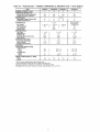
refi'igerant piping, and servicing unit. See Fig. 1-3 for
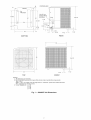
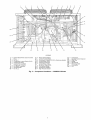
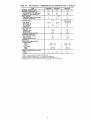
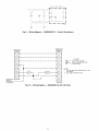
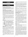
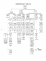
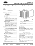
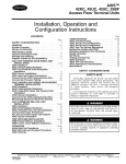
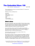
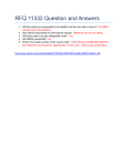
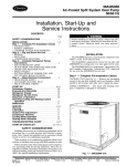
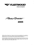
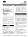
unit dimensions. Figure 4 shows typical component locations for 38AQS016 units.
• Locate unit so that outdoor coil airflow is unrestricted on
all sides and above.
• Unit may be mounted on a level pad directly on the base
channels or mounted on raised pads at support points.
See Tables IA-ID for unit operating weights.
or designs
38A-19SI
without notice and without incurring obligations.
Pg 1
9-04
Replaces: 38A-16SI
B
CONTROL BOX
f
FRONT
\
4 PLACES
Line & Low
_
19 3/8
Voltage Wiring
35
/
2 / 1/2
Entrances
5-3
38-1/2
_
1-;/2
t2-1/8
@
9-3/4t
1-I/8
rTTTT_TTTT
J
D
2-1/2
4-1/4
11/2
1-1/2
REAR
BOTTOM
33
35
i
38-1/2
iii
33
TOP
1-1/2
FRONT
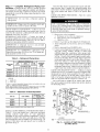
NOTES:
1, All dimensions are in inches,
2, Recommended clearance for proper airflow (local codes or jurisdictions may prevail):
Top -- 60 in,
Sides -- 24 in, on 3 sides; one side may have 6-in. clearance. (Control box side should have
24qn, clearance for service access.)
3. Corner Weights (Ib): A = 86
B =84
C=92
D=90
Fig. 1 -- 38AQ007 Unit Dimensions
CORNER
COMPRESSOR
ACCESSPANEL
_
COIL
IlXll
OUTDOORCOIL
11627
[4578]
REARVIEW
COIL
ACCESS
CORNER
//
"Z
TOP VIEW
ELECTRICAL
LOCATION
CONTROL
ACCESS
PANEL
(SEE
CHART
{SEE
CONNECTION
CHART
FOR SIZE)
LOCATION
FOR
SIZE)
OUTDOORCOIL
i
5825
[2293]
_
OUTLET
6456
[2542]
111.7
E440]
FORKTRUCK
SLOTS
(3 SIDESONLY)
LEFT
2268
[8983
1751
[6.90]
[459]
,,D.7
15093
[5942]
FIELD
ENTRYSERVICEPORT
SIDE VIEW
FRONTVIEW
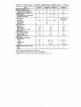
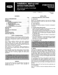
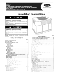
SERVICE VALVE CONNECTIONS
Unit
38ARQO08
38ARQ012
Vapor
1V 8
13/8
Liquid
V2
V2
t_
Center of Gravity,
/
Direction of airflow,
Dimensions
in [
] are in inches.
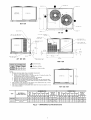
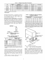
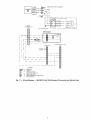
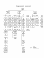
NOTES:
1. Minimum clearance (local codes or jurisdiction may prevail):
a. Bottom to combustible surfaces: 0 inches.
b, Outdoor coil, for proper airflow: 36 inches one side, 12 inches the other. The
side getting the greater clearance is optional.
c. Overhead: 60 inches, to assure proper outdoor fan operation.
d. Between units: Control box side, 42 inches per NEC.
e. Between unit and ungrounded surfaces: Control box side, 36 inches per NEC.
f, Between unit and block or concrete walls and other grounded surfaces, control
box side, 42 inches per NEC.
2. With exception of the clearance for the outdoor coil as stated in Note 1B, a removable fence or barricade requires no clearance,
3. Units may be installed on combustible floors made from wood or Class A, B or C
roof covering material,
ALUMINUM
UNIT
ELECTRICAL
CHARACTERISTICS
Std.
Unit
Wt.
Ib
38ARQ008
38ARQ012
kg
Ib
Ib
kg
Corner
Z
464210120541426410849
94
43
208/230-3-60,575_3_60460-3-60,
506230120541687612758
91
42
Fig. 2-
kg
Corner
Y
872
[34
RIGHT SIDE VIEW
COPPER COILS
kg
460-3-60
Ib
Corner
X
ACCESS
PANEL
COIL
Ib
208/230-3-60,
kg
Corner
W
OUTDOOR COIL
Center of
Gravity
[mm (in.)]
X
812.8
[32,00]
889.0
[35,00]
Y
660,4
[26,00]
666,8
[26,25]
Std.
Unit
Wt.
Ib
kg
Corner
W
Ib
58525613561
kg
Corner
X
Ib
kg
Ib
kg
173791446511351
60727513059203921667510849
38ARQO08,012 Unit Dimensions
Corner
Y
Corner
Z
Ib
kg
Center of
Gravity
[mm (in,)]
X
850,9
[33.50]
927,1
[36.50]
Y
635.0
[25.00]
641.4
[25.25]
t/2 ° DIA. (4) MTG. HOLES
{13 meO
--(972
158
38 1/4"
mm)--_
(72)
2
243
26 11116"
(678 mm)
_1_
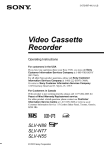
38AQS016
1
158
(72}
3
244
(111)
WEIGHT DISTRIBUTION
LJ
WEIGHT -- Ib (kg)
L
4
(S? u)
UNIT
38AQS
Total
Operating
Weight
1
2
3
4
803
(364)
158
(72)
243
(110)
244
(111)
158
(72)
016
REHOVASLE
Support Point
1 5/8"
ODM VAPOR
5°-9 311G*
(1757 r_)
BETWEENROUNTI_ HOLES
(1016
ram)
BETWEEN MOUNTING
HOLES
SEE DETAIL "A" FOR
HOUNTIN6LEG5 ACCESSORY
2*_7°
(1118 mm)
m
(51 m) K,0.
HAIH PONER 5bPPLY
OUTDOOR
COIL
(1
81DEU)
/
•
13"
2 -41- 0
(732 N)
3"-_ Z"
B
(1013 mm)
(O_ALL)
8
CONTROLPOWER
(22 mr,) SUPPLY
[ !" D|A.
3"i_°
IS"
(916 m_
2"-3
Fs
(710 m)
r 0' -2*
¥
(5t
0'
I 3" DIA. K.O. (SUCTION LINE)
4
(44 ram)
(12 ram)
1 1"
DIA* K,O. (LIGUID LINE}
(32 ram)
4
(171 mm}
END
VIEW
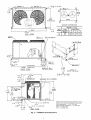
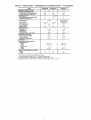
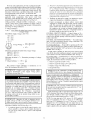
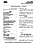
Fig. 3 --38AQS016
Unit Dimensions
NOTE: Recommended service clearances are as
follows (local codes or jurisdictions may prevail):
Side (compressor) --31/2 ft (1067 ram)
Side (opposite compressor) -- 3 ft (914 mm)
Ends-- 2 ft (616 mm)
Top -- 5 ft (1524 mm)
1
2
3
4
5
6
7
8
9
10
11
12
14
15
28
16
26
©
25
24
23
22
21
©
20
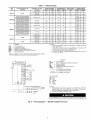
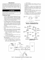
LEGEND
1
23
4
5
6
7
8
9
10
----------
Defrost Board/Time Guard II Control
Fuse
Fan No. 1
Compressor Lockout Device (CLO)
Outdoor-Fan Relay
Outdoor-Fan Contactor
Compressor Contactor
Fan Motor Capacitors
Circuit Breaker
Fan No. 2
Fig. 4--
11
12
13
14
15
16
17
18
19
20
-----------
Power Terminal Block
Control Terminal Block
Compressor Lockout (CLO2 for Crankcase
Control Relay (CR3)
Liquid Line Solenoid
Control Relay (CR2)
No Dump Relay (NDR)
Oil Pressure Switch
Fusible Plug (hidden)
High-Pressure Switch
Component
Heater)
Locations -- 38AQS016 Shown
2122
23
2425
26
2728-
-----
Compressor
Capacity Control Solenoid
Filter Drier
Muffler
Oil Solenoid
Reversing Valve
Accumulator
Coil
Table 1ANOMINAL
Physical Data-
38AQ007, 38ARQ008,012,
38AQS016 Units-
UNIT
38AQ007
38ARQ008
CAPACITY (tons)
6
7.5
OPERATING
WEIGHTS
I
I
I10
34514641506
N/A
15
565
607
I
20
1
I
I
20
9
I
I
22
9
37
3
Scroll
1""SR-75
1""ZR12588
I 1""ZR-94
90
N/A
3500
(cfm total)
OUTDOOR COILS (Oty)
Face Area (sq ft total)
Rows...Fins/in.
Storage Capacity (Ib)**
CONTROLS
Pressurestat
Settings (psig)
High Pressure
Open
Close
Low Pressure
Open
Close
603
945
R-22
COMPRESSOR
PIPING CONNECTIONS
Vapor
Liquid
38AOS016
(Ib)
Aluminum-Fin
Coils
(standard)
Copper-Fin Coils
(optional)
REFRIGERANT*
Operating Charge, Typical (Ib)'l"
Shipping Charge (Ib)
Qty._Model
Oil Charge (oz)
No. Cylinders
Speed (rpm)
OUTDOOR FANS
Qty...Rpm
Diameter (in.)
Nominal Hp
Nominal Airflow
Watts (total)
I 38AR0012
60 Hz English
Semi-hermetic
reciprocating
I
110
1...06DF537tl-128
6
1750
1 ...1100
26
3/4
6300
750
2...1100
22
'/4
6500
570
2...1075
26
'/2
11,OO0
1460
1
24
2...18
17.3
2
29.2
2...17
34.2
1
29.2
3...15
40.1
420
300
I
428_+10
320
_+20
I
395_+20
295
_+20
20
5
I
227_+3
_+5
I
22
7_+3
_+5
I
15/8
5/8
(in. ODM)
*Unit is factory supplied with holding
tTypical operating charge with 25 ft
**Storage capacity of condenser coil
1-tEquipped with an electric solenoid
1'/8
5/8
1'/8
1/2
I
charge only.
of interconnecting pipe.
with 80% full of liquid at 95 R
unloader, capacity steps 100% and 67%.
13/8
1/2
Table 1 B -- Physical Data -- 38AQ007, 38ARQ008,012,
UNIT
NOMINAL
CAPACITY (kW)
OPERATING
WEIGHTS
38AQ007
38ARQ008
I 38ARQ012
I
38AOS016
21.1
26.4
I
35.1
I
52.7
15712101230
N/A
256
275
R-22
I
10
I
4.1
I
365
430
(kg)
Aluminum-Fin
Coils
(standard)
Copper-Fin Coils
(optional)
REFRIGERANT*
Operating Charge, Typical (kg)l"
Shipping Charge (kg)
9
.5
I
I
9
4.1
17
1.3
Scroll
COMPRESSOR
Qty._Model
Oil Charge (L)
No. Cylinders
Speed (r/s)
OUTDOOR FANS
Qty...r/s
Diameter (mm)
Nominal kW
Nominal Airflow (L/s total)
Watts (total)
OUTDOOR COILS (Qty)
Face Area (sq m total)
Rows...Fins/m
Storage Capacity (kg)**
CONTROLS
Pressurestat Settings (kPag)
High Pressure
Open
Close
Low Pressure
Open
Close
PIPING CONNECTIONS
Vapor
Liquid
38AQS016 Units -- 60 Hz Sl
1""SR-75
1""ZR1252.6
I 1""ZR-94
2.7
N/A
58
Semi-hermetic
reciprocating
I
3.3
1...06DF5371-1-3.8
6
29
1...18
660
.56
3000
750
2,,,18
560
.19
3070
570
2,,,18
660
.37
5190
1460
1
2.2
2,..708
7.9
2
2.7
2.,,670
15.5
1
2.7
3...590
18.2
2900
2070
I
2950_+ _+138
2200
70
I
2725_+135
2035
_+ 135
140
35
I
150
48_+20
_+35
I
150
48_+20
_+35
I
18/8
5/8
(in. ODM)
1'/8
5/8
1'/8
1/2
I
*Unit is factory supplied with holding charge only.
1-Typical operating charge with 7.6 m of interconnecting pipe.
**Storage capacity of condenser coil with 80% full of liquid at 36 C.
1-1-Equipped with an electric solenoid unloader, capacity steps 100% and 67%.
13/8
1/2
Table lC -- Physical Data -- 38ARQ008,012
UNIT
and 38AQS016 Units -- 50 Hz English
38ARQ008
OPERATING WEIGHTS (Ib)
Aluminum-Fin
Coils (tons)
(standard)
NOMINAL
CAPACITY
Copper-Fin Coils (optional)
REFRIGERANT*
Operating Charge, Typical (Ib)t
Shipping Charge (Ib)
464
6.3
565
508
8.3
607
38AQS016
803
12.5
945
R-22
I
I
Scroll
22
9
1...ZR_94
|
1...ZR125
90
t
NA
I
2900
2900
37
3
Semi-hermetic
reciprocating
1...06DF5371-t
110
128
6
1450
2...920
22
OUTDOOR COILS (Qty)
Face Area (sq ft total)
Rows...Fins/in.
Storage Capacity (Ib)**
CONTROLS
Pressurestat Settings (psig)
High Pressure
Open
Close
Low Pressure
Open
Close
PIPING CONNECTIONS
Vapor
Liquid
I
I
20
9
COMPRESSOR
Qty._Model
Oil Charge (oz)
No. Cylinders
Speed (rpm)
OUTDOOR FANS
Qty...Rpm
Diameter (in.)
Nominal Hp
Nominal Airflow (cfm total)
38ARQ012
2...900
28
1/4
1/2
5800
7400
2
29.2
2...17
34.2
1
29.2
3...15
40.1
428 _+10
320 _+20
I
I
22_+5
395 _+20
295 _+20
22_+5
(in. ODM)
11/8
1/2
7_+3
13/8
I
1/2
*Unit is factory supplied with holding charge only.
tTypical operating charge with 25 ft of interconnecting pipe.
**Storage capacity of condenser coil with 80% full of liquid at 95 R
1-tEquipped with an electric solenoid unloader, capacity steps 100% and 67%.
1s/8
7_+3
5/8
Table 1D -- Physical Data -- 38ARQ008,012
UNIT
NOMINAL
CAPACITY (kW)
OPERATING WEIGHTS (kg)
Aluminum-Fin
Coils (standard)
Copper-Fin Coils (optional)
REFRIGERANT*
Operating Charge, Typical (kg)t
Shipping Charge (kg)
and 38AQS016 Units -- 50 Hz Sl
38ARQ008
38ARQ012
38AOS016
22.1
29.2
43.9
210
256
230
275
365
430
R-22
9
4.1
I
I
Scroll
10
4.1
1...ZR 94
/
1...ZR125
2.7-
t
NA
I
3.3
COMPRESSOR
Qty._Model
Oil Charge (L)
No. Cylinders
Speed (r/s)
OUTDOOR FANS
Qty...r/s
Diameter (ram)
Nominal kW
Nominal Airflow (L/s total)
58
OUTDOOR COILS (Qty)
Face Area (sq m total)
Rows...Fins/m
Storage Capacity (kg)**
CONTROLS
Pressurestat Settings (kPag)
High Pressure
Open
Close
Low Pressure
Open
Close
PIPING CONNECTIONS
Vapor
Liquid
17
1.3
Semi-hermetic
reciprocating
1...06DF537tt
3.8
6
29
58
2...15
560
.19
2740
2...15
660
.37
3500
2
2.7
2...670
15.5
1
2.7
3...590
18.2
2950_+ 70
2200 _+138
I
I
2725_+135
2035 _+135
48 _+20
150 _+35
I
I
48 _+20
150 _+35
(in. ODM)
11/8
13/8
I
1s/8
1/2
1/2
I
5/8
*Unit is factory supplied with holding charge only.
tTypical operating charge with 7.6 m of interconnecting pipe.
**Storage capacity of condenser coil with 80% full of liquid at 36 C.
1-tEquipped with an electric solenoid unloader, capacity steps 100% and 67%.
Step 3 -nections-
Complete
Refrigerant
Piping
Con-
Select the filter drier for maximum unit capacity and minimum pressure drop. Complete the refrigerant
piping fi'om
indoor unit to outdoor unit before opening the liquid and vapor
lines at the outdoor unit. Refer to Table 4 for specific filter
driers.
Refi'igerant lines nmst be cm'efully designed
and constructed to ensure equipment reliability and efficiency.
Line length, pressure drop, compressor oil leturn, and vertical
separation ;u'e several of the design criteria that must be evaluatedi See Table 2.
LIQUID LINE PIPING
liquid line as follows:
I
IMPORTANT:
underground.
Do
not
bury
refrigerant
piping
IMPORTANT:
Piping must be properly
installed for the system to operate efficiently.
sized
Table
2 --
Refrigerant
LENGTH
0-25
(0-7,5)
OUTDOOR
UNIT
OF PIPING
Piping
I
1. Open service valves in sequence:
a. Discharge service valve on compressoc
b. Vapor service valve on compressor.
c. Liquid line valve.
2. Remove l/4-in, flare cap from liquid vCdve Schmder port.
3. Attach refi'igerant recovery device and recover holding
charge.
4. Remove runaround loop (38AQS016 only).
5. Connect system liquid line from liquid connection of outdoor unit (38AQ, 38ARQ,
38AQS) to indoor unit
(40RMQ) liquid line connections.
Select proper fieldsupplied bi-flow filter driers and install in the liquid line.
See Fig. 5. Install a field-supplied liquid moisture indicator between the filter drier(s) and the liquid connections
on the indoor unit. Braze or silver ¢flloy solder all connections. Pass nitrogen or other inert gas through piping
while making connections to prevent formation of copper
oxide. (Copper oxides me extremely active under high
temperature and pressure. Failure to prevent collection of
copper oxides may lesult in system component failures.)
]
I
]
I
Sizes
ft (m)
26-60
(7,8-18.0)
Line Size (in. OD)
L
V
MAXIMUM
LIQUID
LINE*
(in. OD)
61-100
(18.3-30)
L
V
L
V
38AQ007
1_
1 l&
5/8
1 l&
5&
11½
38ARQ008
3/8
1 l&
1_
1 l&
1_
1 l&
38ARQ012
V2
13/8
1_
13&
1_
13&
38AQS016
5/8
18&
3/4
18&
3/4
18&
%
%
%
3/4
LIQUID LINE SOLENOID
VALVE -- Addition of a liquid
solenoid valve (LLSV) is required (except for 38AQS016 units
that aheady have LLSV factory-installed).
The LLSV must be
a bi-flow type suited for use in heat pump systems. Refer to
Table 4 for specific refrigerant specialty p_uts. Wire the solenoid valve in pargfllel with the complessor contactor coil.
The LLSV must be installed at the outdoor unit with the
flow mTOW pointed toward the outdoor unit (in-flow direction
for the Heating mode).
LEGEND
L
V
---
Liquid Line
Vapor Line
*if there is a vertical separation
between indoor and outdoor units, see
Table 3 -- Maximum Vertical Separation.
NOTE: Approximately
4 elbows assumed in determining
pipe sizes. Maximum length of interconnecting
piping is 100 ft (30.5 m).
EQUALIZER LINE
INDOOR
COIL CKT 2
Table 3 -- Maximum Vertical Separation*
UNIT 38
*Vertical
UNIT
40RMQ
AQ007
008
50 (15.2)
008
60 (18.3)
ARQ012
012
60 (18.3)
AQS016
016
80 (24.4)
distance
between
indoor
and outdoor
TXV
SENSING
BULB
CAPACITY CONTROL
SOLENOID VALVE
¢
DISTANCE
FT (M)
Unit 38
Above Unit 40RMQ
ARQ008
system
Unit is pressurized with a holding charge of refi'igerant.
Recover R-22 holding charge before removing runaround
liquid piping loop. Failure to recover holding charge before
removing piping loop could result in equipment &_mage
and sevele pel.sonal injury.
]
REFRIGERANT
LINE SIZING -- Consider the length of
the piping required between the outdoor and indoor units. The
maximum _dlowable line length is 100 ft (30.5 m). See Table 2.
Refiigerant vapor piping should be insulated.
IMPORTANT:
For 38AR0008,012
applications
with
liquid lift greater than 20 ft (6 m), use 5/s-in. liquid line.
Maximum lift is 60 ft (18 m).
the
I
and
is not provided
-- Pipe
]
CHECK VERTICAL SEPARATION
-- If there is any vertic_d separation between the indoor and outdoor units, check to
ensure that the separation is within allowable limits. Relocate
equipment if necesstuy. See Table 3.
IMPORTANT:
A refrigerant
receiver
with the unit. Do not install a receiver.
PROCEDURE
SIGHT GLASS
A LOCATION
AIRFLOW
MIN
TXV
FILTER DRIER
__)KT
2
A LOCATION
10
INDOOR
COIL CKT 1
,FILTER
CRIERS
B LOCATION
units.
INDOOR
COIL
INSTALL FILTER DRIER(S) AND MOISTURE
INDICATOR(S)Every unit should have a filter drier and liquidmoisture
indicator
(sight glass).
In some
applications,
depending on space and convenience requirements, it may be
desirable to install 2 tilter driers and sight glasses. One filter
drier and sight glass may be installed at A locations in Fig. 5. If
desired, 2 filter driers and sight glasses may be installed at
13 locations in Fig. 5.
VAPOR AND LIQUID LINE
PIPING FOR SPLWFACE
COIL
DIAMS
MIN
LEGEND
TXV -- Thermostatic Expansion Valve
Fig. 5 --
10
Location
of Sight
and Filter Driers
Glass(es)
Table 4 -- Refrigerant Specialties
UNIT
LIQUID LINE
SIZE
38AQ007
LIQUID LINE
SOLENOID
VALVE (LLSV)
200RB
200RB
1/2"
5/8"
38ARQ008
3/8"
1/2"
38AQS016
5/8......
3/4......
LLSV COIL
5T4
5T5
200RB GS-1928 5T41200RB GS-1928 5T4
1/2"
38ARQ012
GS-1928
GS-1929
200RB
GS-1928
Part Numbers
5T4
SIGHT
GLASS
FILTER
DRIER
AMG-24/50-60
AMG-24/50-60
AMI-1TT4
AMI-1TT5
AMG-24/50-60
AMG-24/50-60
AMI-1TT3
AMI-1TT4
P504-8083S
P504-8084S
AMG-24/50-60
AMI-1TT4
P504-8164S
AM I- 1TT5
AMI-1TT5
P504-8085S
P504-8085S
Qty 2
Qty 2
*A filter drier is shipped loose with the 38AQ007.
1-Bushings required.
**Factory Installed.
Table 6 -- Insulation for Vapor Line Exposed
to Outdoor Conditions
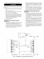
PROVIDE SAFETY RELIEF -- A lusible plug is located on
the compressor crankcase or in the liquid line. See Fig. 6. Do
not cap this plug. If local code requires additional safety
devices, install them as directed.
LENGTH OF EXPOSED
VAPOR LINE*
Head Pressure Control (38AOS016 Only) -- Fan cycling for
head pressure control is a stan&ud offering but is functional in
the cooling cycle only. Number 2 fan cycles as a function of
liquid pressure. Fan cycling pressure switch cycles the fan off
at 160 _+10 psig (1103 _+69 kPag) as pressure decreases and
cycles back on at 255 _+10 psig (1758 _+69). Switch is automatically bypassed in heating cycle. Table 5 shows minimum outdoor air temperature for full cooling capacity without low
ambient controls.
INSULATION
m
in.
mm
10
3
a/8
10
25
8
1/2
13
35
11
s/4
19
50
15
s/4
19
*Recommended vapor line insulation for piping exposed to outdoor
conditions to prevent loss of heating during heating cycle. When
vapor line goes through interior spaces, insulation should be
selected to prevent condensation on cooling cycle. Heating capacity
should be reduced 1000 Btuh (295 W) if over 35 ft (11 m) ef vapor
line with 3/4 in. (19 mm) insulation is exposed to outdoor conditions.
1-Closed cell foam insulation with a thermal conductivity of: 0.28 Btu
• in./ft 2 • h • °F (0.04 W/m • °C).
FUSIBLE PLUG
TXV
BULB CAPILLARY
TUBES
Fig. 6 -- Location of Fusible Plug -38AQS016 Unit
Table 5 -- Minimum Outdoor Air
Operating Temperature
UNIT
38
AQ
007
O08
ARQ -012
AQS
%
COMPRESSOR
CAPACITY
016
40RMQ012
40RMQ016
MINIMUM OUTDOOR
TEMP -- F (C)*
Standard Unit
THICKNESS1-
ft
40RMQ
UNIT
Head Pressure
Control1-
0 (-17.8)
0 (-17.8)
10o
35 (1.7)
-20 (-28.9)
35 (1.7)
-20 (-28.9)
100
67
23 (-5)
36 (2.2)
-20 (-28.9)
-20 (-28.9)
TUBE DIAMETERS
= 7/8" OD
= 1 1/8" OD
8" (208 mm)
15" (381 mm)
MIN
_
MIN
10" (254 ram)
MIN
VAPORLINE
LEGEND
*Applies to Cooling mode of operation only.
1-Wind baffles (field-supplied and field-installed) are recommended
for all units with low ambient head pressure control. Refer to Low
Ambient Control Installation Instructions (shipped with accessory)
for details.
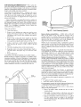
TXV
--
Thermostatic
Expansion Valve
Fig. 7 -- Vapor Line Branch Piping Details
Step 4 -- Complete Electrical Connections
POWER SUPPLY -- Electric_d ch_u'actedstics of available
power supply must agree with nameplate rating. Supply
voltage must be within tolerances shown in Table 7. Phase
imbalance must not exceed 2%. Operation qfunit on improper
SUl)l)@ voltage or with excessive phase imbalance constituWs
abuse and is not corered by Carrier warran O"
VAPOR LINE PIPING PROCEDURE -- Connect system
vapor line to the vapor line stub on the outdoor unit and the
vapor stubs on the indoor unit. At the indoor unit, construct
vapor piping branches as shown in Fig. 7 for good mixing
of the refrigerant leaving the indoor coil during cooling. This
will ensure proper TXV (thermostatic expansion valve) bulb
sensing.
Where vapor line is exposed to outdoor air. line must be
insulated. See Table 6 for insulation requirements.
11
Perloc_fl
codelequimments,
provide
anadequate
fused
disconnect
switch
withinsightofunitandoutofreach
ofchildren.
Provision
forlocking
switchopen(off)isadvisable
toplevent
powerfrombeingturned
onwhileunitis beingserviced.
Tile
disconnect
switch,luses,
andfieldwiringmustcomplywith
localrequilements.
Refer
toTable
7 forelectric_fl
data.
POWER
WIRING- All powerwilingmustcomplywith
applicable
loc_drequirements.
Run powerwires fiom
disconnect
switch
through
unitpoweropening
andconnect
to
terminal
blockinside
theunitcontrol
box.SeeFig.8-13.
UNBALANCED
3-PHASE
SUPPLY
VOLTAGE
-- Never
operate
amotorwhere
aphase
imbalance
in supply
voltage
is
gleater
than2%.Usethefollowingformula
todetermine
the
percentage
ofvoltage
imbalance:
%Voltage
hnbalance:
= 100x max voltage deviation from average voltage
2.
The power-cimuit field supply disconnect should never be
open except when unit is being seia'iced or is to be down
fi_r a prolonged
period
When operation is resumed,
crunkcase heater should be eneqked fi_r 24 hours b@re
start-up. [_ s3_tem is to be shut down fi_r a prolonged
t)eiqod, it is recommended Nat the suction and dischaiig, e
vah'es be closed m prevent an (_rcessive accumulation of
refiqgerant in the conq)ressor oil.
3.
Terminals for field power supply tue suitable for copper.
copper-clad Numinum, or aluminum conductors.
4.
Cturier recommends
an indoor airflow switch (field
supplied) be installed and interlocked with the outdoor
unit. This prevents the outdoor unit fi_)m operating if
indoor airflow Nils (broken Nn belt, etc.). Operafion of
the compressor in vacuum can damage bearing surfaces.
Install indoor airflow switch in a convenient location at
the indoor supply air duct and wire per Fig. 14.
average voltage
CONTROL
CIRCUIT WIRING -- Control voltage is 24 v.
See unit label diagram for field-supplied wiring detNls. Route
control wires through opening in unit end panel to connection
in unit control box.
EXAMPLE: Supply voltage is 460-3-60.
AB = 452 v
BC = 464 v
AC = 455 v
h
B
CONTROL
TRANSFORMER
WIRING -- On multivoltage
units, check the transformer primary wiring connections. See
Fig. 9 or refer to unit label diagram.
¢
For 38AO.ARO Units -- If unit will be operating at 400-3-50
power, remove the black wire (BLK) from the transformer primtuy connection labelled "460" and move it to the connection
labelled "400". See Fig. 9.
3
@
Average Voltage
- 457
=
452 +v 464 + 455
Determine maximum
(AB) 457 - 452 =
(BC) 464 - 457 =
(AC) 457 - 455 =
deviation
5v
7v
2v
Maximum
imbahmce:
is 7 v. Determine
deviation
from average
voltage:
percentage
If unit will be operating at 208-3-60 power, remove black
wire (BLK) from the transformer primtuy connection labelled
"230" and move it to the connection labelled "208". See Fig. 9.
For 38AQS Units -- Transformers no. 1 and 2 are wired for a
230-v unit. |fa 208/230-v unit is to be mn with a 208-v power
supply, the transformers must be rewiled as follows:
1. Remove cap from red (208 v) wire.
of voltage
7
% Voltage hnbalance
=
100 x
=
1.53%
This amount of phase imbalance is satisfactory
below the maximum allowable of 2%.
IMPORTANT:
Contact
your
company
immediately
if the
imbalance is more than 2%.
local
supply
electric
voltage
as it is
utility
phase
Remove cap from orange (230 v) spliced wile.
3.
Replace orange wire with red wile.
4.
Recap both wires.
IMPORTANT:
BE CERTAIN UNUSED WIRES ARE
CAPPED. Failure to do so may damage the transforlner.
]
I
Duplex 38AQS.ARQ
with 40RMQ024 or 40RMQ028 -- In
order to properly connect two heat pump condensing units to a
single 40RMQ packaged air handler, it is necessary to add
field-supplied Fan Coil Relay Board(s), P/N 33ZCRLYBRD.
Relay botud(s) no. 1 and no. 2 should be installed in the control
box of condensing unit.
Unit cabinet must have an uninterrupted, unbroken electrical ground to minimize the possibility of personal injury if
an electrical fault should occm: This ground may consist of
electrical wire connected to unit ground lug in control comp_utment, or conduit approved for electrical ground when
installed in accordance
with NEC (National Electrical
Code) (U.S.A.), ANSI/NFPA
(American National Standards
Institute/National
Fire
Protection
Association)
(U.S.A.), and loc_d electric_d codes. Failure to follow this
w_u'ning could result in the installer being liable for personal injury of others.
IMPORTANT:
Operation
of unit on improper power
supply voltage or with excessive phase imbahmce constitutes abuse and is not covered by Carrier warranty.
2.
IMPORTANT:
The common (COM) terminals from the
fan coil relay board(s) must be connected to the 'C' terminal in condensing unit 'A'.
Route thermostat cable or equiwdent single leads of no. 18
AWG (American Wire Gage) colored wire from subbase terminals through conduit in unit to low-voltage connections
as
shown on unit wiring diagram and Fig. 12 and 13.
NOTE: For wire runs up to 50 ft, use no. 18 AWG insulated
wire (35 C minimum). For 51 to 75 ft, use no. 16 AWG insulated wire (35 C minimum). For over 75 ft, use no. 14 AWG
insulated wire (35 C minimum). All wire huger than no. 18
AWG c_mnot be directly connected to the thermostat and will
require a junction box and a splice at the thermostat.
]
I
GENERAL WIRING NOTES (See Fig. 8-13)
I. A crankcase heater is wired in the control circuit so it is
always operable as long as power supply disconnect is
on, even if any safety device is open or unit stop/stmt
switch is off.
12
Table 7 -- Electrical Data
UNIT
38
NOMINAL VOLTAGE
(V-Ph-Hz)
FACTORY-INSTALLED
OPTION
AQ007
OR DISCONNECT
CONVENIENCE
ARQ008
NONE
OR DISCONNECT
NONE
OR DISCONNECT
CONVENIENCE
NONE
ARQ012
18.9
146
5.1
28.7
45
506
9.5
73
2.6
14.5
20
575-3-60
517
633
7.6
58
1.2
10.7
15
39.0
60
43.8
60
19.8
30
21.9
30
19.8
30
45.0
60
50.0
70
23.0
30
25.0
30
18.0
25
20.0
25
187
NONE
190
1.5
418
506
15.0
95
0.7
400-3-50
360
440
15.0
95
0.7
187
254
34.0
225
1.5
418
506
17.0
114
0.7
OR DISCONNECT
NONE
575-3-60
523
632
14.0
80
0.7
400-3-50
360
440
17.2
125
0.7
22.9
30
208/230-3-60
187
253
63.6
266
4.3
87.5
125
460-3-60
414
528
29.3
120
2.3
40.7
60
575-3-60
518
660
23.8
96
1.8
33.0
50
230-3-50
198
264
47.9
200
3.5
66.9
100
400-3-50
342
457
29.3
115
3.5
43.0
60
OUTLET
OR DISCONNECT
NONE
AQS016
NONE
LEGEND
-------
29.0
460-3-60
460-3-60
OUTLET
CONVENIENCE
FLA
LRA
MCA
MOCP
NEC
RLA
254
OR DISCONNECT
CONVENIENCE
SUPPLY
MOCP
253
208/230-3-60
OUTLET
POWER
MCA
187
OUTLET
NONE
FAN MOTORS
FLA
414
OR DISCONNECT
CONVENIENCE
COMPRESSOR
RLA
LRA
460-3-60
208/230-3-60
OUTLET
RANGE*
Max
208/230-3-60
NONE
NONE
VOLTAGE
Min
NOTES:
1. The MCA and MOCP values are calculated in accordance
with the
NEC, Article 440.
2. Motor RLA and LRA values are established
in accordance
with
Underwriters'
Laboratories
(UL), Standard
1995.
3. The 575-v units are UL Canada-listed
only.
4. Convenience
outlet is available as factory-installed
option only and
is 115-v, 1 ph, 60 Hz.
Full Load Amps
Locked Rotor Amps
Minimum Circuit Amps
Maximum Overcurrent Protection
National Electrical Code (U.S.A. Standard)
Rated Load Amps
*Units are suitable for use on electrical systems where voltage
to the unit terminals is not below or above the listed limits.
supplied
LEGEND
DF
LP/HP
PS
RV
SEN
TSTAT
"[ DEFROSTr_T_V- _
q;ArCONTRO __ __
J
- Y
14
i
i
-
#'LP/HP
-¥ -(_
R C
COLOR CODE
BK
BL
O
R
W
Y
O Y W
R
I
I
LW._____DEFROSTHEAT
i
_- i
i
i_
i
L
_
--COMPRESSOR
i
-O--
---It--
_------4---BL-----_---R
--HEAT/COOL
J
COMMON
_--
Defrost Relay
Low- or High-Pressure Switch (Optional)
Pressure Switch
Reversing Valve
Outdoor Coil Temperature Sensor
Thermostat
Line Voltage Factory Wiring
Low Voltage Factory Wiring
Low Voltage Field Wiring
4
BL--
-
-BL
-------
Black
Blue
Orange
Red
White
Yellow
NOTES:
1. All electrical work must be done in conformance
with the
National Electrical Code (NFPA No. 70) and in conformance
with local codes and authorities having jurisdiction.
2, For use with copper conductors only.
24 VAC
Not suitable for use on systems exceeding 150 volts to ground,
Fig. 8 -- Wiring Diagram -- 38AQ007 208/230-3-60 Units
13
460V
_
I
!
TRAN CONFIG
I
I
!
,
i
!
!
_{_
TRf, N
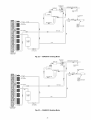
Fig. 9 -- Wiring Diagram -- 38ARQ008,012
CONNECTION
BOARD (TB)
THERMOSTAT
(3(3(3C)- -q
@
(3C)TO ELECTRIC
HEATER
ACCESSORY
IF EQUIPPED
-- Control Transformer
C)
.C)
.C)
Q
G
-©
4Z)
Q
r
I
I
I
I
Fig. 10 -- Wiring Diagram -- 38ARQ008,012
14
LEGEND
IFC
-LLSV -TB
--
Indoor Fan Contactor
Liquid Line Solenoid Valve
Terminal Block
NOTES:
1. For thermostat and subbase part no. see
price pages.
2, Use copper conductors only.
230-3-60 Units
]FM
40RMQ
UNiT
WIRING
4ORMQ ELECTRIC
HEAT ACCESSORY
....
-J
THERMOSTAT
38AQS TERMINAl
TB2
BLOCK
REMOVE
JUMPER
L
LEGEND
EQUIP
GND
HC
IFC
IFM
NEC
TB
--------
Equipment
Ground
Heater Contactor
Indoor Fan Contactor
Indoor Fan Motor
National Electrical Code (U.S.A.)
Terminal Block
Fig. 11 -- Wiring Diagram -- 38AQS016 Unit With Standard
15
Thermostat and Electric Heat
TB1
I_FLEL_D
_ _ _
BISCONNECT__P_OW_E_R
o_lHCl_
_ _]|
_
-
I
__?_UP_PL_y _ _HCI_
EQUIP
__-rr'_
3-PhONLY
GND
c
I
j
4
I
I Ir
i i CIRCUlTBREAKER
(5 HPAND LARGER)
' %"
IFC
I
I- I-
HTR1
]
, , ,- - -[---"_q@_BLK_------m
I
40RMQ024
TERMINALBLOCKTB1
_-
]
-
4 d_II_-BLK_
WIRINGEIELDPOWER
E
E
E
)IFM;
-_@I_-BLK-_____j/
!
UNITWIRING
J
40RMQ
HEAT ACCESSORY
HEATPUMP"A"
E
E -WHT_]
F;- --WHT
I
J
I
I
I
I
._/
I
11
I --
TB2
[]
i
I
CA
RELAY
E
r_
E
[] /VALVE/q--HI(COOL)
I
'
---D i_
[]
-
-
_1_1
-
TSTAT
i
1
, ,___
I
I
i_i_
_
I
I
I
I
_
BOARD
/33ZORLYBRD/
I
I_
I
FAN--/
MED(HEAT)----_
ILO--
/'
-
'
_.
I
I
HEAT
PUMP
"B"
TB2
D
D
52}
LEGEND
CR
EQUIPGND
HC
HTR
IFC
IFM
TB
TSTAT
---------
Control Relay (Field-Supplied)
Equipment
Ground
Heating Contactor
Electric Heater
Indoor-Fan Contactor
Indoor-Fan Motor
Terminal Block
Thermostat
[]
[]
[]
[]
Factory Wiring
Field Control Wiring
[]
NOTE: Use copper conductors only.
Fig. 12 -- Wiring Diagram -- Duplex 38ARQ012 With 40RMQ024 and Electric Heat
16
-II
_1
TB1
_-I
DISCONNECT
l--a
P_OW_ERp_pL_y_IIL21_
S-PhONLY
.ORMOO28
HTR1
1---,
CIRCUIT
BREAKER
5HPANDLARGER
I
I
I
I 11
_
_
FIELD POWER
WIRING
Y'_
HCI_
I
_____
_IFC
_
-"
' _} - - PCfl_@-BLK-_€_
TERMINALTB1BLOCK
-R-_
I
_- _
_p__.___
),FM!
_It_3)-BLK_
I
UNIT WIRING
48RMQ
HEAT ACCESSORY
HEAT PUMP A
38AQSO16
I
G_ -WHT
,
x--I
I
i I
_ -_T_
I
li
I
[]
[]
II
x
I
(33ZCRLYBRD)
I
g
I
--4-
--- _
_
,
_
_,'
I_
_
(VALVE>
I
TSTAT*
;
J I
H'(O°°L/--I,
I
,_
I
_
LI_
G
FAN --
-
-
_[]
t
_
,-I
I
r
I
I
i-
BOARD
!__-
I I
MED(REAT)--I--'
' _
l i ", ' ,I i __I_LO_
RELAY
BOARD/
G
I
RELAY
q,, B
I -
FAN
I
I_
TB2
II
_
I
__:
[]
[]
[]
[]
HEAT PUMP
38ARQO12
I--o
H'/C°°L>--I
(VALVE)
-MED(HEAT)--
I_LO--
I
/
B
LEGEND
CR
EQUIPGND
HC
HTR
IFC
IFM
TB
TSTAT
---------
TB2
Control Relay (Field-Supplied)
Equipment
Ground
Heating Contactor
Electric Heater
Indoor-Fan Contactor
Indoor-Fan Motor
Terminal Block
Thermostat
CR
- -II- -I
[]
[]
[]
[]
[]
[]
Factory Wiring
Field Control Wiring
CR
*Do not configure TSTAT for heat pump.
NOTE: Use copper conductors only.
Fig. 13 -- Wiring Diagram -- Duplex 38ARQ012 and 38AQS016 With 40RMQ028 and Electric Heat
DB
[_--
SPLICE
YEL _
SPLICE
YEL
_
CR3 ,.i,
1
I
I
I
I
I
I
L------I
I-....
AFS
LEGEND
AFS
CR
DB
----
Airflow Switch (Sail Switch)
Control Relay
Defrost Board
--
Factory Wiring
....
Field Control Wiring
NOTES:
1. Locate YEL wire between []
on DB and terminal 5 of CR3
and cut.
2. Splice airflow switch (AFS) (field supplied) contact wires (field
provided) to two ends of cut YEL wire as depicted.
Fig. 14 -- Typical Field Wiring for Airflow
38AQS016/40RMQ (Shown)
17
Switch --
I I
PRE-START-UP
c.
IMPORTANT:
Before beginning Pre-Start-Up
or StartUp, review Start-Up Checklist at the back of this book.
The checklist assures proper start-up of the system and
provides a record of unit condition, application requirements, system information,
and operation
at initial
start-up.
Evacuate and dehydiate entire refrigerant system by use
of methods described in GTAC II, Module 4, System
Dehydiation.
38AQS016 only -- compressor oil level should be visible
in sight glass. Adjust the oil level as required. No oil
should be removed unless the crankcase heater has been
energized for at least 24 hours. See Start-Up section,
Preliminary Oil Charge.
NOTE: The 38AQ and 38ARQ units do not have a compressor oil level sight glass. These units are factory
chtu'ged with the required amount of oil.
If required,
use the following oil for replacement:
For 38AQ007 use Zerol 150, part number tx)03-2001.
For 38ARQ008,012
use RCD part number P903-0101.
7.
Do not attempt to sttut tile heat pump system, even
momentmily,
until the following steps have been completed. Compressor damage may result.
Preliminary
Check for leaks.
Checks
1. Check all air handler and other equipment auxiliary components. Consult manufacturer's
instructions regmding
any other equipment attached to unit. If unit has fieldinstalled accessories, be sine _dlare properly installed and
correctly wiled. If used, airflow switch must be properly
installed. See Fig. 14 for typical field wiring.
2. As shipped, compressor is held down by 4 bolts. After
unit is installed, loosen each bolt using locknut until flat
washer or snubber (3/8 in.) can be moved with finger
pressure. Be sure complessor floats freely on the mounting springs and that upper flat washers can be moved with
finger pressure. See Fig. 15A and 15B for compressor
mounting.
3. Check tightness of all electrical connections.
4. Ensme electrical power source agrees with nameplate
rating.
5. Turn on crankcase heater for 24 hours before starting the
unit to be sine all refiigemnt is out of the oil. To energize
crankcase heatel, perform the following steps:
a. Set the space thermostat system switch to OFF. or
adjust the temperature
so there is no demand for
cooling.
b. Close the field disconnect.
c. Leave the compressor circuit breaker off. The crankcase heater is now energized.
6. Leak test the field lefrigemnt piping, connections and
joints, and the indoor coil. To perform leak test, complete
the following steps:
a. Pressurize refrigerant piping; do not exceed 150 psi.
b. Using soap bubbles
and/or an electronic
leak
detector, test refrigerant
piping, connections
and
joints, and the indoor coil. See Fig. 16.
SELF-LOCKING
-____
BOLT
_
_SNUBBER
_
NEOPRENE
COMPRESSOR
3/8"-16
LOCKNU_
m 03'X; 'IAGE
3/8"-16
BOLT
CARRIAGE
3/8"
BOLT_
FLAT
_
3/8"-16
LOCKNUT
WASHER
_._.__Lf
'
FOOT
COMPRESSOR
FOOT
SPRING
SPRIN
COMPRESSOR
_SPACER
1/2" FLAT
_f
NUTS
WASHER_
FRONT
NUTS
VIEW
_WASHER
REAR VIEW
Fig. 15B -- Compressor Mounting -38AQS016 Units
DRY
NITROGEN
LIQUID
LINE
SOLENOID
VALVE
INDOOR
COIL
OUTDOOR
UNIT
W
Recommended
FOOT
Fig. 15A -- Compressor
Mounting -38AQ007 and 38ARQ008,012
Units
150 PSI MAX
Fig. 16 --
WASHER
_
Process
18
for Checking
for Leaks
8. Backseat (open) compressor vapor and discharge valves.
Now close valves one turn to _dlowrefiigerant pressure to
reach test gages.
Preliminary
Charge
2.
Turn off power to the unit, tag disconnect.
3.
4.
Reverse any two of the unit power leads.
Reapply power to the compressol: verily correct pressures.
The vapor and dischtuge pressure
to their norln¢fl start-up levels.
levels should now move
Compressor
Overload -- This overload interrupts
power to the compressor when either the current or internal
motor winding temperature becomes excessive, and automatically resets when the intern;d temperature drops to a safe level.
This overload usually resets within 60 minutes (or longer). If
the intermfl overload is suspected of being open, disconnect the
electrical power to the unit and check the circuit through the
overload with an ohmmeter or continuity testel:
The 38ARQ008
and 38ARQ012
units contain a 9 lb
(4.1 kg) charge of refrigerant. Add remainder of preliminary charge and allow pressure to equalize before starting
compressoc Failure to do so WILL cause the compressor
to oveltleat in a few minutes, possibly causing permanent
compressor &_mage. The amount
of refrigerant
added
must be at least 80% of the operating
charge listed in
the Physical Data table (Tables 1A-1D).
Advanced
Scroll
Temperature
Protection
(ASTP)
-- Advanced
Scroll
Temperature
Protection
(ASTP) is a form of internal discharge temperature protection
that unloads the scroll compressor when the internal temperature reaches approximately 300 IF.At this temperatme, an internal bi-metal disk valve opens and causes the scroll elements to
sepm'ate, which stops compression. Suction and discharge pressures balance while the motor continues to run. The longer the
compressor runs unloaded, the longer it must cool befole the
bi-metal disk resets. See Fig. 17.
Before starting the unit, charge liquid refrigerant into the
high side of the system through the liquid service valve. Allow
high and low side pressures to equalize before stm-ting compressol: If pressures do not equalize readily, charge vapor on
low side of system to assure charge in the evapomtol: Refer to
GTAC II, Module 5, Charging, Recovery. Recycling, and Reclamation for liquid charging procedures.
Liquid Line Solenoid -- To minimize refrigerant migration to the compressor during the heat pump OFF cycle, the
To manually reset ASTP. the complessor should be stopped
and allowed to cool. If the compressor is not stopped, the motor
will mn until the motor protector trips, which occurs up to
90 minutes latel: Advanced Scroll Temperatme Protection will
reset automatically
before the motor protector resets, which
may take up to 2 hours. A label located above the terlninal box
identities Copeland Scroll compressor models (ZR94, 108 and
125) that contain this technology. See Fig. 18.
38AQ,ARQ unit must have a bi-flow liquid line solenoid v;dve
(field supplied). The valve opens when the compressor is energized, and closes when the compressor
is deenergized.
This
reduces compressor flooded st_u-ts,thus significantly increasing
compressor life.
Accumulator
-- qn_e unit accumulator controls the rate of
liquid ret]igemnt to the compressor during heat pump operation.
The 38AQS accumulator
features a unique method for
returning oil to the compressor
The oil return mechanism is
external to the accumulatol: The mixture of oil and refrigerant
is metered to the compressor by a brass orifice which is removable and cleanable. The oil return mechanism also contains a
solenoid valve that opens when the compressor
is ON and
closes when the compressor
is OFF. This keeps the liquid
refrigerant stored in the accumulator
from di'aining to the
compressor during the heat pump OFF cycle, which further
protects the compressor against flooded starts.
J
jJ
J
J
J
jJ
J
START-UP
0
10
20
Compressor
Compressor
crankcase
heater
must be on for 24 hom:s
before st_ul-up. After the heater has been on for 24 hours,
the unit can be started.
30
40
Unloaded
50
Run
60
Time
70
80
90
(Minutes)
*Times are approximate. Various factors, including high humidity,
high ambient temperature, and the presence of a sound blanket
will increase cool-down times.
Fig. 17Recommended Minimum Cool-Down
Time After Compressor is Stopped*
Prior to starting compressol: a preliminary ch_uge of refrigerant must be added to avoid possible compressor dmnage.
Compressor
Rotation
(38AQ,ARQ
Units) --
On
3-phase units with scroll compressors, it is important to be certain compressor is rotating in the proper direction. To determine
whether or not compressor is rotating in the proper direction:
1. Connect service gages to suction and discharge pressure
fittings.
2. Energize the compressol:
3. The vapor pressure should &up and the discharge pressure should rise, as is normal on any start-up.
If the vapor pressure does not drop and the discharge
pressure does not rise to normal levels:
1. Note that the condenser fan is probably also rotating in
the wrong direction.
Fig. 18 -- Advanced Scroll Temperature
Protection Label
19
O_DOOR
Compressor
Lockout (CLO) Device-Tile Compressor lockout (CLO) device prevents the compressor fiom
stariing or running in a high pressure, loss-of-chmge
or
fieezestat open situation. Reset the CLO device by setting the
thermostat to eliminate cooling demand and return it to the ong_
inal set point, ff the system shuts down again for the stone fault,
determine the possible cause before attempting to _eset the CLO
device.
Preliminary
Oil Charge (38AQS)
iiiiIlilllll ,lllJl Jtllilii
iiiiiL!oL
o!Liiiiiii
LL ! I_
,lO
.............
IlllllYiil
55-
_'5¢-
_45"
liilllill
,<
-- Tile compressor
,oo
is factory chm'ged with oil (see N_bles IA-ID). When oil is
checked at stml-up, it may be necess;uy to add or remove oil
to bring it to the proper
level. Add oil only if necessary to
bring oil into view in sight glass. Use only Carrier-al)l)nn'ed
¢Xm_l)ressor oil. One recommended
oil level adjustment
method is as follows:
ii
lllllllH'lllll!
1
illi,I/lllltiillli
il_lL!o!ltllllll
I
I
°o!illl!lli
50
1
1
1
1
I
I
_111111111 illllllllllll
III11111
illllllllllllllllllll
E0,
Petroleum Specialties, Inc .....................
Cryol 150A
Texaco, Inc ...............................
Capella WF32
Witco Chemical Co ..........................
Suniso 3GS
Do not use oil that has been &'ained out, or oil that has been
exposed to atmosphere.
iiiiiliii iili
_illlll,rllltlill
illllHIIIIllll!
1
iliili
_111111
ADD OIL--Close
vapor service valve and pump down
crankcase to 2 psig. Wait a few minutes and repeat until pressure remains steady at 2 psig. Remove oil fill plug above the
sight glass, add oil through plug hole, and replace plug. Run
compressor for 20 minutes and check oil level.
NOTE: Use only Carrier approved compressor oil. Approved
sources are;
REMOVE OIL -- Pump down compressor to 2 psig. Loosen
the l/4-in, pipe plug at the compressor base and allow the oil to
seep out past the threads of the plug. RetigNen plug when level
is correct.
FAN MUST BE OPE_TING
1_1111111111111111111111111111
II
!
_o
IIIIIIIIIIIII111111
I_
IIII
lll!llil!llll!ltll!ll
1_
1_
Fig, 19A-
2_
250
_0
PRE_URE
AT LIQUID
VALVE
(PSIG)
LIQUID
PRE_URE
AT _QUID
VALVE
(kPa)
38AQ007
Charging
400
_0
LIQUID
Chart
6O
54
/
ADD
CHARGE
IF ABOVE
CURVE
/
ku
>
49
/
¢
/
4_
/
38
NOTE: The crankcase is slightly pressurized. Do not remove
the plug, or the entire oil charge will be lost.
Small amounts of oil can be removed through the oil pump
discharge connection while the compressor is running.
/
/
32
/
27
/
/
Start Unit
21
-- Tile field disconnect is closed, the fan circuit
bleaker is closed, and the space thermostat is set above ambient
so that there is no demand for cooling. Only the crankcase
heater will be energized.
Next, close the compressor circuit breaker and then reset
space thermostat below ambient so that a call for cooling is
ensured.
NOTE: Do not use circuit bleaker to start and stop the complessor except in an emergency.
After starting, there is a delay of at least 3 seconds before
compressor starts.
/
REDUCE
CHARGE
IF BELOW
CURVE
/
16
/
10
50
100
150
200
LIQUID
344
6;9
1034
LIQUID
Fig. 19B-
250
PRESSURE
AT LIQUID
1;79
PRESSURE
300
VALVE
1724
AT LIQUID
38ARQ008,012
350
2089
VALVE
400
(PSIG)
2414
(Kilopascals)
Charging Chart
70-
Adjust Refrigerant Charge
-- Refer to Charging Charts
Fig. 19A-19C and Table 8. Do not exceed maximum refrigerant charge. Vmy refrigerant until the conditions of the chart are
met. Note that chmging charts are different from type normally
used. Chmls are based on chmging the units to the correct
subcooling for the various operating conditions. Accurate pressure gage and temperature sensing device me required.
Connect the pressure gage to the service port on the liquid
line service valve. Mount the temperature sensing device on
the liquid line, close to the liquid line service valve and insulate
it so that outdoor ambient temperature does not affect the reading. Indoor airflow must be within the normal operating range
of the unit. Operate unit a minimum of 15 minutes. Ensure
pressure and temperature readings have stabilized. Plot liquid
pressure and temperature on chm't and add or reduce charge to
meet curve. Adjust charge to conform with charging chmt,
using the liquid pressure and temperature to read chart.
If the sight glass is cloudy, check refrigerant charge again.
EiIsure all fims arc ol)erating. Also ensme maximum allowable
liquid lift has not been exceeded. If charged per chmt and if the
sight glass is still cloudy, check for a plugged filter drier or a
pmtially closed solenoid v¢flve. Replace or repair, as needed.
65*
0_60.
_J
>,55<
> 5045-
-_ 40'_ 35w
3025-
20"
5-
t00
150
LIQUID
200
250
300
PRESSURE
AT LIQUID
350
VALVE
400
(PSIG)
7;0 _doo_so' _oo' roB' _oo_2ao' _soo'2z;o
LIQUID
Fig.
2O
PRESSURE
19C -- 38AQS016
AT LIQUID
Charging
VALVE
(kPa)
Chart
450
'
3000
When the thermostat is satisfied, the circuits me opened,
and the compressor, outdoor-fan motor, heatel_, and indoor-fan
motor stop.
Never charge liquid into the low-pressure
side of system.
Do not ovemharge.
During charging
or removed of refrigerant, be sum indoor-fan
system is operating.
DEFROST -- Defrost board (DB) is a time and temperature
control, which includes a field-selectable
time period between
checks for frost (30, 50, and 90 minutes). Electronic timer and
defrost cycle start only when contactor is energized and defrost
thermostat (DFT) is closed (below 28 F [-2.2 C]).
Defrost mode is identical to Cooling mode, except outdoorfan motor (OFM) stops and a bank of supplemental
electric
heat turns on to wmm air supplying the conditioned space.
Defrost mode is terminated
when the DFT reaches 65 F
(l 8.3 C).
Chmge unit on cooling cycle only. If unit is charged on
heating cycle, overch;uging may occm:
Checking
Heating Cycle Operation -- Place thermostat selector switch at HEAT and reset the space set
point above mnbient temperature so that a call for heating is
ensured. Compressor
will start within 5 minutes. Observe
system operation.
AIR CIRCULATION
-- When the fan switch is at FAN ON,
the indoor-air fans operate continuously to provide ventilation.
The thermostat operates the other components
as described
above.
Check Compressor Oil Level (38AQS) --After adjusting the refngerant charge, allow the systeln to run fully
EMERGENCY
HEAT CYCLE -- If the compressor is inoperative due to a tripped safety device, the second stage of the
thermostat automatically energizes the indoor-air fan and the
electric resistance heaters (if equipped).
loaded for 20 minutes. Running oil level should be within view
in the crankcase sign glass. Stop compressor at the field power
supply disconnect and check the crankcase oil level. Add oil
only if necessary to bring the oil into view in the sight glass. If
oil is added, mn the system for an additional 10 minutes, then
stop and check oil level. If the level lemains low, check the
piping system for proper design for oil return; _dso check the
system for leaks.
38ARQ008,012
Units--When
unit, the mmsformer
(TRAN)
heater is also energized.
power
is energized.
is supplied to
The crankcase
If the initial check shows too much oil (too high in the sight
glass) lemove oil to proper level. See Preliminary Oil Charge
section for proper procedme for adding and removing oil.
COOLING--With
the thermostat subbase in the cooling
position, and when the space temperature comes within 2° F
(1 ° C) of the cooling set point, the thermostat makes circuit
R-O. This energizes the reversing valve solenoid (RVS) and
places the unit in standby condition for cooling.
When the above checks me complete, repeat the procedure
with the unit operating at minimum load conditions. Unload
the com_sor
by disconnecting the field-control circuit lead
at TB2 _.
Reconnect the field-control circuit lead when checks are
complete.
As the space temperature continues to rise, the second stage
of the thermostat makes, closing circuit R-Y. When compressor
time delay (5 _+2 minutes) is completed, a circuit is made to
contactor (C), staffing the compressor (COMP) and outdoorfan motor (OFM). Circuit R-G is made at the same time,
energizing the indoor-fan
contactor (IFC) and starting the
indoor-fan motor (IFM) after one-second delay.
Final Checks
When the thermostat is satisfied, contacts open, deenergizing C. The COMR IFM, and OFM stop.
HEATINGOn a call for heat, thermostat makes circuits
R-Y and R-G When compressor time delay (5 _+2 minutes) is
completed, a circuit is made to C, starting COMP and OFM.
Circuit R-G also energizes lFC and starts IFM after a 1-second
delay.
-- Ensure ;ill safety controls are operating,
control panel covers me on, and the service panels are in place.
Table
Refrigerant Charge
8 -- Maximum
R-22
UNIT 38
AQ007
ARQ008,012
AQS016
SEQUENCE
38AQ007
transformer
(Ib)
27.0
(kg)
12.2
34.2
34.2
62.0
15.5
15.5
28.1
38AQS016
Units
HEATING
-- Place therlnostat selector at HEAT and set temperature selector above room ambient.
COOLING -- Place thermostat selector at COOL and set temperature selector below room mnbient.
OF OPERATION
UnitsWhen power is supplied to unit, the
(TRAN) and crankcase heater (CCH) ale energized.
When thermostat c_dls for unit operation (either heating or
cooling),
the indoor-fan
motor starts immediately.
The
outdoor-fan motors and compressor start within 3 seconds to
5 minutes depending on when unit was last shut off by thermostat, because unit contains a compressor
time delay circuit.
When first-stage cooling is required, thermostat (TCI) closes,
causing the heat pump to stmt with an unloaded compressol:
When TC2 closes, demanding additional cooling, the compressor loads to full load operation.
COOLING -- On a call for cooling, the thermostat completes
the following circuits: R-G. R-Y. and R-O. If the compressor
recycle delay of 3 minutes is complete, the compressor ;rod
outdoor fan start. The reversing valve is energized for cooling
and the indoor-fan motor starts.
When the thermostat is satisfied, the circuits are opened,
and the compressol: outdoor-fan motol: and indoor-fan motor
stop. The reversing valve is deenergized.
During heating, compressor is always fully loaded. When
THI demands first-stage heating, the heat pump starts within
3 seconds to 5 minutes depending on when unit was last shut
off by thermostat, because unit contains a compressor
time
delay circuit. (The defrost bomd has speed terminals to shorten
this cycle.) When TH2 of the thermostat closes, auxilimy heat
supply (electric strip heat) is energized in 1 or 2 stages depending on number of stages available and whether outdoor thermostats are closed.
HEATING -- On a c;dl for heating, the thermostat completes
the following circuits: R-G and R-Y. If the compressor recycle
delay of 3 minutes is complete, the compressor and outdoor
fan st_u't. The indoor-fan motor will also staff.
If room temperature
continues
to fall, the thermostat
completes circuit R-W. If the optional electric heat package is
used, the heat relay is energized, and the electric heaters are
energized.
21
Defrostis achieved
by reversal
fiom heating
to cooling
cycleanddeenergization
of outdoor-fan
motol.'s,
allowing
hot
refrigerant
gastodefrost
outdoor
coil.Defrost
isachieved
with
a timersetto initiatedefrostevery30,50,or 90minutes
(factory
setat30minutes).
Defrost
isinitiated
whenrefrigerant
temperature
leaving
the
outdoor
coilismeasured
below27F (2.8C),(typically
when
theoutdoor
ambient
temperature
is below45F [7.2C] as
sensed
bythedefiost
thermostat
[DFTI).
Defrostis terminated
when:Therefrigerant
temperature
rises
to65F(18.3C)(80F[26.7C]for38AQS016)
attheDFT
location
ontheliquidline;ortherefrigerant
pressure
risesto
280psig(1931kPag)
attheHPS2
location
ontheliquidline;or
thedefiost
timercompletes
the10-minnte
cycle.
Duplex
DUPLEX
Fig. 12)
system can be reset by adjusting the thermostat to open the
contacts (down for Heating mode, up for Cooling mode), deenergizing the CLO. Compressor
overcurrent
protection
is
achieved with a circuit breaker which requires manual resetting at the outdoor unit control box (38AQS only).
The 38AQS unit is equipped with an oil pressure safety
switch that protects the compressor if oil pressure does not develop on start-up or is lost during operation. The oil pressure
switch is of the manual reset type and therefore must be reset at
the outdoor unit. DO NOT RESET MORE THAN ONCE.
If oil pressure switch trips, determine cause and correct. DO
NOT JUMPER OIL PRESSURE SAFETY SWITCH.
To reset the oil pressure switch:
1. Disconnect power to the unit.
2. Press the RESET button on the oil pressure switch.
3. Reconnect power to the unit.
Units
38ARQ012
UNITS
WITH
40RMQ024
(See
Unit is equipped with a no-dump reversing valve circuit.
When unit is in Cooling mode, reversing valve remains in cooling position until a call for heating is requested by themlostat.
When unit is in Heating mode, reversing valve remains in heating position until there is a call for cooling.
Cooling -- When the thermostat is set for cooling, and the
space temperature comes within 2 ° F (1 o C) of the cooling set
point, the thermostat completes the circuit from R to O and the
reversing valves in both units are energized. If the space temperature continues to rise, the circuit from R to YI is completed. If the time delays and safeties are satisfied, the compressor
contactor closes, starting the compressor
and outdoor-fan
motors of Heat Pump A. At the same time the circuit is
completed from R to G. starting the indoor-fan motor. If the
space temperature continues to rise, the circuit is completed
from R to Y2 and the Cooling mode is initiated in Heat Pump
B in a similar mannec
CHECK OPERATION
-- Ensure operation of all safety controis. Replace zfll service panels. Be sure that control panel
cover is dosed tigh@
Restart
--Manu_fl
reset of the 24-v control circuit is
necessa q if unit shutdown is caused by automatic reset devices
(including
IP [internal compressor
overcurrent
protectionl,
HPS [high-pressure switchl, LCS [loss-of-charge switchl), or if
shutdown is caused by manual reset devices (including OPS
[oil pressure switchl and compressor circuit breaker protection). To restart the unit when IR HPS, or LCS has tripped (@
Wr device has reset automati_zd@), open and then close the
thermostat contacts. Opening and then closing thermostat contacts interrupts and restores 24-v power to the CLO, which
resets the circuit.
When the thermostat is satisfied, the contacts open, deenergizing first the Heat Pump B and then Heat Pump A.
Heating -- When the thermostat c_dls for heating, the circuit
fiom R to YI is completed. If the time delays and safeties are
satisfied, the compressor contactor closes, sttuting the compressor and outdoor-fan motors of Heat Pump A and Heat
Pump B. At the same time the circuit is completed from R to G.
st_uting the indoor-fan motol: If the second stage of heating is
required, the circuit from R to W2 will be completed and the
electric resistance heaters will be energized.
It is necessary to manu_dly reset the compressor
breaker and OPS at the unit if either of these safeties
shut down the unit.
When the thermostat is satisfied, the contacts open, deenergizing Heat Pump A and Heat Pump B.
DUPLEX
38AQS016
AND
40RMQ028 (See Fig. 13)
38ARQ012
UNITS
cimuit
should
IMPORTANT:
If OPS trips, it must be reset fi_t before
making and b_eaking the thermostat
contacts to reset
CLO. If this procedure is not followed, the CLO cannot
_eset.
WITH
Cooling -- When the thermostat calls for cooling, the circuit
from R to YI is completed. If the time delays and safeties are
satisfied, the compressor contactor closes, sttuting the compressor and outdoor-fan motors of Heat Pump A (38AQS016).
At the same time the circuit is completed form R to G. stmling
the indoor-fan motol: If the space temperature continues to rise,
the circuit is completed from R to Y2 and the Cooling mode is
initiated in Heat Pump B (38ARQ012).
Causes
•
•
•
•
•
•
•
•
When the thermostat is satisfied, the contacts open, deenergizing first the Heat Pump B and then Heat Pump A.
Heating -- When the thermostat c_dls for heating, the circuit
from R to WI is completed. If the time delays and safeties are
satisfied, the compressor contactor closes, st_uting the complessor and outdoor-fan motors of Heat Pump A and Heat
Pump B. At the same time the circuit is completed from R to G.
st_uting the indoor-fan motol: If the second stage of heating is
required, the circuit from R to W2 will be completed and the
electric lesistance heaters will be energized.
of Complete
Unit Shutdown:
interruption
of supplied power
open compressor overtemperature
protection (IP)
compressor electrical overload protection (CB)
open high-pressure
or loss-of-charge
safety switches
open oil pressure switch
open crankcase heater lockout (CLO2)
open control circuit fuse (FUI or FU2)
open discharge gas thermostat (38ARQ only)
SERVICE
Compressor
Removal
pressor information.
Follow
glasses and work gloves.
-- See Tables IA-ID for comsafety codes and wear safety
1. Shut off power to unit. Remove unit access panel.
2.
Recover refrigerant from system using refrigerant recovery
methods described in C;urier Training booklet GTAC |I,
Module 5, and in accordance
with loc:d and national
stan&_rds.
3.
Disconnect
box.
4.
Disconnect
When the thermostat is satisfied, the contacts open, deenergizing Heat Pump A and Heat Pump B.
SAFETIESThe high-plessure
switch,
loss-of-charge
switch, oil pressure safety switch, and compressor overtemperature safety are located in a CLO that prevents heat pump
operation if these safety devices are activated. The lockout
22
compressor
refrigerant
wiring
at compressor
lines from compressol:
termimd
5. Remove screws fiom compressor mounting plate.
3.
Excessive movement of copper
cause higher levels of vibration
service.
Subcooled
refrigerant
liquid leaves the coil circuits
through the side outlet on the liquid headers. The liquid
refrigerant from each coil flows through check valves
"B" which are open, enters the liquid line and goes to the
indoor coil.
4.
The liquid refrigerant is expanded and
indoor coil resulting in low pressure
pressure vapor returns to the outdoor
system vapor line, reversing valve,
reentering the compressor at the suction
lines at compressor may
when unit is restored to
6.
Remove or disconnect
base.
7.
Remove compressor
8.
On 38AQS016 unit remove compressor
and lift compressor off mounting plate.
9.
Clean system. Add new liquid line filter &ier
10.
crankcase
heater from compressor
from unit.
holddown
38ARQ008, 012 Heating
(See Fig. 21)
bolts
Install new compressor
on compressor mounting plate
and position in unit. Connect vapor and discharge lines to
compressor. Secure mounting plate with compressor to
unit. Ensure that compressor holddown bolts are in place.
Connect wiring. Install crankcase heatel:
2.
Check valve "B" blocks the flow of liquid and the liquid
refrigerant must flow through the filter driers, through
check v_dve "C", and into the liquid header assembly.
3.
The liquid refrigenmt is expanded as it passes through the
fixed orifice metering devices into outdoor coil circuits.
The refrigerant evaporates as it passes through the coil
circuits resulting in low plessure vapol:
4.
The low pressure
the vapor headers,
to the compressor
and accumulator,
connection.
Restore unit powel:
38ARQ008, 012 Cooling
(See Fig. 20)
Mode Operation
1. High pressure, high temperature refrigerant vapor from
the compressor flows through the reversing v_flve and is
directed to the vapor headel:s of both outdoor coils.
2.
Mode Operation
1. High pressure, high temperature refrigerant vapor from
the compressor flows through the reversing valve and
is directed through the system vapor line to the indoor
coil. Refrigerant
is condensed
and subcooled in the
indoor coil and returns to the outdoor unit through the
system liquid line.
11. Evacuate and rechmge unit.
12.
At the outdoor coil vapor header, the high pressure, high
temperature refrigerant vapor flows up to check valve
"A" that blocks the flow. All the refrigerant is then
directed to flow into the coil circuits.
COMPRESSOR
_
REVERSING
vapor leaves the coil circuits and enters
check valves "A" are open, and returns
through the vapor line, revelling valve,
reentering the compressor at the suction
VALVE
[_]ZZZ1
_M
evaporated in the
vapol: This low
unit through the
and accumulatol:
connection.
LAT4(_OR
U
_
VAPO_'_RLINE
BALL
VALVE
FROM
INDOOR
UNIT
vel
FILTER
DRIER
TO
LIQUID LINE
[_INDOOR
METERING DEVICE
FIXED ORIFICE
BALL
VALVE
Fig. 20 -- 38ARQ008, 012 Cooling Mode (Size 008 Shown)
23
UNIT
COMPRESSOR
_
REVERSING
VALVE
TO
?M
AT_'_O
UL
R
_
VAPOR-_LINE
INDOOR
UNIT
BALL
VALVE
?
d&
CK VALVE B
CK VALVE A
CK VALVE C
1]
f
II
FILTER
DRIER
LIQUID LINE
FIXED ORIFICE
METERING
DEVICE
[_
BALL
VALVE
FROM
INDOOR
UNIT
Fig. 21 -- 38ARQ008, 012 Heating Mode (Size 008 Shown)
38AQS016
Cooling
Mode Operation
(See Fig. 22)
2.
Check valve "B" blocks the flow of liquid and the refiigerant is then directed to flow through check wtlve "C"
(which is open), through the filter drier, and into the
liquid header assembly.
The liquid refrigerant is expanded as it passes through the
capillary tubes into outdoor coil circuits. The refrigerant
evaporates as it passes through the coil circuits resulting
in low plessure vapol:
The low pressme vapor leaves the coil circuits and enters
the vapor headek check valve "A" is open, and returns to
the compressor through the vapor line, leversing v;dve,
and accumulator. _eentering the compressor at the suction
connection.
I.
High pressure, high temperature lefrigemnt vapor froln
the compressor flows through the reversing valve and is
directed to the outdoor coil vapor headel:
3.
2.
At the outdoor coil vapor headel: the high pressure, high
temperature refrigerant vapor flows up to check valve
"A" that blocks the flow. All the refrigerant is then
directed to flow into the coil circuits.
4.
Subcooled
refrigerant
liquid leaves the coil circuits
entering the portion of the vapor header which is above
check valve "A". Check valve "C" is closed, therefore,
the liquid refrigerant passes through check valve "B,"
which is open, and enters the liquid line and goes to the
indoor coil.
4.
The liquid refrigerant is expanded and
indoor coil resulting in low pressure
plessure vapor returns to the outdoor
system vapor line, reversing valve,
reentering the compressor at the suction
Heating
(See Fig. 23)
38AQ8016
I.
Crankcase
Heater--The
crankcase
refrigerant
migration and compressor
oil
shutdown when compressor is not operating.
evaporated in the
vapor This low
unit through the
and accumulator.
connection.
Close both compressor
service valves
heater is deenergized for more than 6 houL's.
heater
prevents
dilution
when
during
crankcase
Outdoor Unit
Fans--Each
fan is supported
by a
formed-wire mount bolted to the fan deck and covered with a
wire guard. On the 38AQS016, the exposed end of the motor
shaft is covered with a rubber boot. In case a fan motor must be
repaired or leplaced, be sure the rubber boot is put back on
when the fan is reinstalled and be sure the fan guard is in place
before stmting the unit.
Mode Operation
High pressure, high temperature lefrigemnt vapor froln
the compressor flows through the reversing valve and
is directed through the system vapor line to the indoor
coil. Refrigerant
is condensed
and subcooled in the
indoor coil and returns to the outdoor unit through the
system liquid line.
Lubrication--Fan
motors
have permanently
bemings. No further lubrication is required.
24
sealed
REVERSING
VALVE
REFRIGERANT
MIXTURE
f
FROM INDOOR
COiL
TO INDOOR
COIL
ACCUMULATOR
CN
GAS AND OIL
LIQUID
LLSV
_[J
./
ANGLE
VALVE
WITH SCHRADER
PORT
HOT GAS
j
CK VALVE C
COIL RETURN
BEND END
Fig. 22 --38AQS016
Cooling
Mode
REVERSING
VALVE
REFRIGERANT
MIXTURE
DOlL
TO INDOO_R
FROM
COIL
_
GAS AND OIL
_
CK VALVE B
--
_
/
LLSV
_
J
ANGLE
VALVE
WITH SCHRADER
PORT
CK VALVE A
HOTGAS
CK VALVE C
COIL RETURN
BEND END
Fig. 23 -- 38AQS016 Heating Mode
25
LIOUID
INDOOR
/
j
Coil Cleaning and Maintenance--This
section discusses the cleaning and the maintenance of standard coils and
E-Coated coils. Routine cleaning of coil surfaces is essential to
minimize contamination build-up and remove harmful residue.
Inspect coils monthly and clean as required.
CLEANING
STANDARD
COILS -- Standard coils can be
cleaned with a vacuum cleaner, washed out with low velocity
water, blown out with compressed ail; or blushed (do not use
wire brush). Fan motors _u'e dripproof but not waterproof. Do
not use acid cleaners.
Clean coil annually or as required by location or outdoor air
conditions. Inspect coil monthly and clean as required. Fins are
not continuous through coil sections. Dirt and debris may pass
through first section and become trapped, restricting condenser
airflow. Use a flashlight to determine if dirt or debris has
collected between coil sections.
SPREAD
OUTER COIL
SECTIONS
OLFi3NARD
3
Clean coils as follows:
Fig. 25 -- Coil Cleaning (Typical)
1. Turn off unit powel:
2.
Remove screws holding rear corner posts and top cover
in place. Pivot top cover up 12 to 18 in. (300 to 450 mm)
and support with a board or other adequate rigid support.
See Fig. 24.
3.
Remove clips securing tube sheets together at the return
bend end of the coil. Carefully spread the ends of the coil
rows apart by moving the outer sections. See Fig. 25.
4.
Using a water hose or other suitable equipment, flush
down between the sections of coil to remove dirt and
debris.
5.
Clean the lemaining
6.
Reposition outer coil sections. Reinstall clips which secure tube sheets, and replace top cover and rear corner
posts.
Remove Surface Loaded Fibers -- Debris such as dirt and
fibel;s on the surface of the coil should be removed with a
vacuum cleanel: If a vacuum cleaner is not available, a soil
brash may be used. The cleaning tool should be applied in the
direction of the fins. Coil surfaces can be easily damaged (fin
edges bent over) if the tool is applied across the fins.
NOTE: Use of a water stream, such as a garden hose, against a
surface loaded coil will drive the fibel.'s and dirt into the coil.
This will make cleaning efforts more difficult. Surface debris
must be completely removed prior to using low velocity clean
water rinse.
surfaces in the normal mannel:
Periodic Clean Water Rinse --A periodic clean water rinse is
very beneficial for coils that are applied in coastal or industri_fl
environments.
Howevek it is very important that the water
rinse is made with very low velocity water stream to avoid
damaging the tin edges. Monthly cleaning is recommended.
7. Restore unit powel:
CLEANING
AND MAINTAINING
E-COATED CO[LS -Routine cleaning of condenser coil surfaces is essential to maintain proper operation of the unit. Elimination of contamination
and removal of harmlul residue will greatly increase the life of
the coil and extend the life of the unit. The following maintenance and cleaning procedures gue recommended as Dul of the
routine maintenance activities to extend the life of the coil.
TOP
COVER
Routine Cleaning of E-Coated Coil Surfaces
-- Monthly
cleaning with Environmentally
Sound Coil Cleaner is essential
to extend the life of coils. It is recommended that all coils including stan&trd aluminum, pre-coated, copper/coppek or E-coated
coils be cleaned with the Environmentally
Sound Coil Cleaner
as described below. Coil cleaning should be Du-t of the regularly
scheduled maintenance procedures of the unit to ensure long life
of the coil. Failure to clean the coils may result in reduced durability in the environment.
Environmentally
Sound Coil Cleaner
is non-bacterial,
biodegra&tble and will not harm the coil or sunounding components such as electric_d wiring, painted metal surfaces or insulation. Use of non-recommended
coil cleaners is strongly discouraged since coil and unit durability could be affected.
RIGID
SUPPORT
The following field supplied equipment is required
cleaning:
• 21/2 gallon (9.5 liter) garden sprayer
• water rinse with low velocity spray nozzle
for coil
Environmentally
Sound Coil Cleaner Application
Instructions
-- Perform the following procedure to clean the coil.
NOTE: Wear
during mixing
1. Remove
vacuum
Fig. 24 -- Pivot and Support Top Cover
26
proper eye protection such as safety glasses
and application.
all surface debris and dirt from the coil with a
cleaner
2.
Thoroughly wet finned surfaces with clean water _md a
low velocity garden hose, being careful not to bend tins.
3.
Mix Environment_dly Sound Coil Cleaner in a 21/2 g_dlon
(9.5 liter) garden sprayer according to the instructions
included with file cleaner. The optimum solution temperature is 100 F (37.8 C).
6.
DO NOT USE water in excess of 130 F (54.4 C).
Enzymes in coil cleaner will be destroyed and coil cleaner
will not be effective.
4.
5.
Thoroughly
rinse all surfaces with low velocity clean
water using downward rinsing motion of water spray
nozzle. Protect fins from damage from the spray nozzle.
Do not use bleach, harsh chemicals, or acid cleaneLs on outdoor or indoor coils of any kind. These types of cleaneLs me
difficult to rinse, and they promote rapid corrosion of the tin
collar -- copper tube connection. Only use the Environmentally Sound Coil Cleanel:
Thoroughly apply Environmentally
Sound Coil Cleaner
solution to all coil surfaces including finned _uea, tube
sheets, and coil headers. Hold gmden sprayer nozzle
close to finned areas and apply cleaner with a vertic_d,
up-and-down
motion. Avoid
spraying
in horizontal
pattern to minimize potential for fin dmnage. Ensure
cleaner thoroughly penetrates deep into finned _ueas.
Interior and exterior finned areas must be thoroughly
cleaned.
Never use high pressure air or liquids to clean coils. High
pressures damage coils and increase the airside pressure
&op. To promote unit integrity, follow cleaning and maintenance procedures in this document.
Allow finned surfaces to remain wet with cleaning solution for 10 minutes. Ensure surfaces are not _dlowed to
dry before rinsing. Reapply cleaner as needed to ensure
10-minute saturation is achieved.
27
TROUBLESHOOTING
CHART--
HEATING
CYCLE
INSUFFICIENT
I
t
1
I
I
I
RUNSBUT
COMPRESSOR
CYCLESOFF
I
I
I
HEATING
OR
I
1
WILLNOTRUN
COMPRESSOR
NO
I
I
COMPRESSOR
RUNS, tNSUPFtCIENTttEATING
I
DISCHARGE
CONTACTOR
OPEN
._
CLOSED
CONTACTOR
SWITCH
__{HIGH-PRESSURE
LOW VAPOR
LOW HEAD
PRESSURE
GAS
THERMOSTAT
1
I
I
I
OR
____[
VALVES
DEFECTIVE
DIRTY
INDOORFILTERS
COIL
I
OP,
v_jGsH
/ VA P(_R A T
OUTDOOR
FAN
RUNNING
STOPPED
OUTDOOR
FAN
L
HIGit HEAD
LOW
VAPOR
PRESSURE
I
I
t
COMPRESSOR
1
I
COMPRESSOR
FLOODING
LIQUID
LINE
OR
STRAINER
RESTRICTED
]
1
COILORCONTACTS
CONTROLRELAY
DEFECTIVE
__[
VOLTAGE
OR UN
BALANCED
LOW LINE
3-PHASE
LINE
CYCLING
ON
OVERLOADFANS
INDOOR
1
OUTDOOR
MOTOR
_[LOOSELEADSAT]
METERING
DEVICE
RESTRICTED
OR
UNDERCHARGED
SYMPTOMS
FAN
iCE CLOGGED
I
_,_
VALVE
RELAY
REVERSING
DEFECTIVE
._
SEIZED
COMPRESSOR
_{
AT
LOOSE
FAN MOTOR
LEADS
t
INDOOR
COIL
HEADERCHECK
VALVESTUCK
OPEN
COMPR ESSO R
BEARINGS
SYSTEM
OVERCHARGED
1
Do
._
BREAKER
OPEN
CIRCUIT
COIL
DEFECTIVE
CONTACTOR
i[
CYCLE=LOC
TM
COMPRESSOR
CIRCUIT
F
1
BREAKER
CIRCUIT
OPEN
._
,._
BURNED
OUT
FAN MOTOR
REVERSING
DAMAGED
VALVE
CONDITION
HIGH
LOAD
I
1
"_
CHECK VALVE
STUCK
CLOSED
OUTDOORHEADER
BURNED
OUT
PAN MOTOR
OUTDOOR
DIRTY
I
I
SABLES
NONCONDEN
I
I
N.C.
1
RESTRICTED
HIGH
COIL
CIRCUIT
._
DISCHARGE
LINE
RESTRICTtONIN
I
VAPOR
LOW HEAD
PRESSURE
CONTACTS
I
I
CHECK
VALVE
(C)
OPEN
OUTDOOR
COIL
HEAVILY
FROSTED
VALVE
POWER
I
ou;_oo_
C_EC_
JAMMED
tN MID
REVERSING
POSITION
I
VOLTAGE
TRANSFORMERLOWDEFECTIVE
SWITCH
CYCUNG
LOSS-OF_CHARGE
I
DISCHALGE
GAS
I
T H_ _cMLIONS_AT
I
...{
THERMOSTAT
IN
POOR
CONTACT
DEFROST
WITH LINE
LEGEND
-_
___
CCH
DEFECTIVE
SWITCH
OPEN
OIL PRESSURE
1
_{
__.[
DEFROST
RELAY
OR TIMER
DEFECTIVE
VALVE
REVERSING
STUCK
1
CCH -N.C. --
Crankcase Heater
Normally Closed
TROUBLESHOOTING
CHART
I
I
I
I
I
t +N+_c_o_
_t °NTA++o_
I
OPEN
CLOSED
POWER CIRCUIT
OPENING
IN
t
1
,_
POWER SUPPLY
COMPRESSOR
1
I
SWITCH
HIGH-PRESSURE
I
__[
-!
VOLTAGE
DEFECTIVELOWTRANSFOEMER
BREAKER
CIRCUIT
OPEN
AI
J
FAN MOTOR
I
COIL OR CONTACTS
CONTROLRELAY
DEFECTIVE
t
I
__
l
""f
OR
COIL
CONTACTOE
DEFECTIVE
I
__[
REMOTECONTEOL
DEFECTIVE
CENTER
[
CIRCUIT
OFF
1
OPEN WINDINGS
COMPR ESSQ R
MOTOR
I ++++1
SEIZED
COMPRESSOR
DEFECTIVE
MOTOR
I
q
RESTRICTED
OR
OUTDQOR
AIR
RECIRCULATING
CYCLE
LOG
OMPRESSOR
CIRCU_
t
TM
I
,
I -I +++°"
I_
LOW HEAD
PRESSURE
AIR DIR/Y
FILTERS
J
I
4
I
I
.,GR_RORJ
LOW !IFAD
PRESSU_IE
I
,._
]
"--t
REVERSING
VALVEIN
MID POSITION
OUCT I
RESERICTED
VOLiAGE
LINE
PROBLEMS
BEARINGS
COMPRESSOR
MOTOR
i
OVERLOAD
OPEN
REFRIGERANT
SYMPTOM
_A.MOTOR1
OEPECTJVE
I
RUNNINGFAN
INDOOR
DISCHARGE
RESTRICTED LINE
I
GREATLY
RESTRICTED
!NDOOR
AIR
'_E°lc°'L
]
FROSTED
1
t
.,OHV_,+.I
LOW SUPERHEAT
I
INTERNAL
LE_,K
COMPRESSOR
4 co,LI
I°+L+,_I_
t +o_
_
I
I
S
[
SWITCH
_IGH-PRESSURE
CYCLING
REFRIGERANT
SLIGHTLY
CHARGE LOW
I
]
NOT
CONTROLLING
VALVE
LEAKING
OR Ba, CKWARDS
NOT
CONTROLLING
SY+ASS J
O_°OOR_OI,
NE_DER
CHECK
MALVE STL_CK OPEN
J
]
l
TXV
INDOOR
RESTRICTED
l
RESTRICTED
LIQUID
LINE
I
I
DISCHARGE
IRERMOSIAI
CYCLING
GAS
I
'F
SWITCH
OPEN
OIL PRESSURE
l
FII
TEN DRIER
RESTRICTE:)
t
CCH
OE F ECq-IME
]
I
LIONID LINECHECK
OUTDOOR
COl L
VALVE
STUCK
LEGEND
CCH -TXV --
I
I
J
I
+t,+
R ESTRICTED
FILTER
DRIER
VAI VE "JOT
EUI t YOPEN
I
CHECK VALVE
STUCK OPEN
I
LOS_OI
DIIAli_!
SWI ICII CYCLING
NO DI iA_GE
LOW_,'OR
RESTRICTED
I
J
I
HIGH HEAD
PRESSURE
++°+'_
+++°_ °°+++_
+°°,.+I I +++
J
I
I '_'_i_
REVERSING
DAMAGED
VALVE
NONCO_DENSABLER
OVERCHARGEOR
IN SYSTEM
I
INDOOR
COIL
FREEZE
UP
FAN
INDOOR
STOPPED
ELECIRIC&L
LOOSE
CONNECZiON
1
INSUFFICIENT
COMPRESSOR
GGOUNG RUNS
I
DEFROST
RELAY
CONTACTS
ATLOOSE
COMPRESSOR
LEADS
BREAKER
t
J-t
COMPRESSOR
NOT
COMPRESSOR
VALVES
OR
HEADGASKETS
I
I
1
OR
I
I
O;EN
t
GAS
DISDItA_tGE
THERMOSTAT
CYCLE
I
I
RUNS BUT
COMPRESSOR
CYOLESOFF
WILL
NOT RUN
COMERESSOR
I
INSUFFICIENT
NO COOLING
COOLING
-- COOLING
Crankcase Heater
Thermostatic Expansion Valve
TXV NOT
CONTBQLLINI
,.°°o_oo,_
Copyright 2004 Carrier Corporation
Manufacturer reserves the right to discontinue,
PC 111
or change at any time, specifications
Catalog No. 533-80118
Printed in U.S.A.
or designs without notice and without incurring obligations.
38A-19SI
Pg 30
9-04
Replaces: 38A-16SI
START-UP
I. PRELIMINARY
OUTDOOR
INDOOR
INFORMATION
UNIT: MODEL
UNIT: MODEL
ADDITIONAL
CHECKLIST
NO.
NO.
SERIAL
NO.:
SERIAL
NO.:
ACCESSORIES
II. PRE-START-UP
OUTDOOR
IS THERE
UNIT
ANY SHIPPING
DAMAGE'?
(Y/N)
IF SO, WHERE:
WILL
THIS DAMAGE
CHECK
POWER
PREVENT
SUPPLY.
UNIT START-UP?
DOES IT AGREE
HAS THE GROUND
WIRE
HAS THE CIRCUIT
PROTECTION
ARE THE POWER
BEEN CONNECTED'?
WIRES
HAVE COMPRESSOR
(Y/N)
BEEN
(Y/N)
WITH UNIT'?
(Y/N)
(Y/N)
SIZED
AND INSTALLED
PROPERLY'?
TO THE UNIT SIZED
AND INSTALLED
PROPERLY'?
HOLDDOWN
BOLTS BEEN LOOSENED
(Snubber
(Y/N)_
(Y/N)
washers
are snug, but not tight)'?
CONTROLS
ARE THERMOSTAT
CONNECTIONS
AND INDOOR
MADE
FAN CONTROL
AND CHECKED'?
ARE ALL WIRING
TERMINALS
HAS CRANKCASE
HEATER
BEEN
PLACED
IN DRAIN PAN TO CONFIRM
INDOOR
(including
WIRING
(Y/N)
main power supply)
ENERGIZED
TIGHT'?
(Y/N)
FOR 24 HOURS'?
(Y/N)
UNIT
HAS WATER BEEN
ARE PROPER
AIR FILTERS
HAVE FAN AND MOTOR
IN PLACE'?
PULLEYS
DO THE FAN BELTS HAVE PROPER
HAS CORRECT
FAN ROTATION
DRAINAGE'?
(Y/N)
ALIGNMENT'?
(Y/N)
(Y/N)
BEEN CHECKED
TENSION'?
BEEN
PROPER
FOR PROPER
(Y/N)
CONFIRMED'?
(Y/N).
PIPING
HAVE LEAK CHECKS
BEEN MADE
AT COMPRESSOR,
TXVs (Thermostatic
Expansion Valves),
PLUGS WITH A LEAK DETECTOR'?
LOCATE,
REPAIR,
AND REPORT
HAVE ALL COMPRESSOR
HAS LIQUID
IS THE OIL LEVEL
OUTDOOR
VALVES,
UNIT. INDOOR
FILTER DRIERS,
UNIT.
AND FUSIBLE
ANY LEAKS.
SERVICE
LINE SERVICE
SOLENOID
(Y/N)
VALVES
BEEN FULLY
VALVE BEEN OPENED'?
IN COMPRESSOR
CRANKCASE
OPENED
(BACKSEATED)?
(Y/N)
(Y/N)
VISIBLE
IN THE COMPRESSOR
SIGHT
GLASS'?
(Y/N)
CHECK
VOLTAGE
LINE-TO-LINE
IMBALANCE
VOLTS:
AB
(AB + AC + BC)/3 = AVERAGE
MAXIMUM
VOLTAGE
DEVIATION
IMBALANCE
FROM
VOLTAGE
AVERAGE
V
AC
=
V
BC
V
V
VOLTAGE
=
V
= 100 X (MAX DEVIATION)/(AVERAGE
IF OVER 2% VOLTAGE IMBALANCE,
DO NOT ATTEMPT
CALL LOCAL POWER COMPANY FOR ASSISTANCE.
CL-l
VOLTAGE)
=
TO START SYSTEM!
%
III. START-UP
CHECK
INDOOR
FAN SPEED
CHECK
OUTDOOR
AFTER
AT LEAST
AND RECORD.
FAN SPEED AND RECORD.
10 MINUTES
RUNNING
TIME, RECORD
THE FOLLOWING
MEASUREMENTS:
COOLING
HEATING
OIL PRESSURE
VAPOR PRESSURE
VAPOR LINE TEMP
DISCHARGE
PRESSURE
DISCHARGE
LINE TEMP
ENTERING
LEAVING
OUTDOOR
OUTDOOR
AIR
AIR TEMP
INDOOR
ENTERING-AIR
DB (dry bulb) TEMP
INDOOR
INDOOR
ENTERING-AIR
LEAVING-AIR
WB (wet bulb) TEMP
DB TEMP
INDOOR
LEAVING-AIR
WB TEMP
LU
2:
m
COMPRESSOR
AMPS
(LI/L2/L3)
CHECK THE COMPRESSOR
OIL LEVEL
OIL LEVEL IN VIEW'?
(Y/N)
/
SIGHT
GLASSES;
/
/
ARE THE SIGHT
GLASSES
/
SHOWING
c_
LU
I--
rm
Z
o,
<
Io
NOTES:
LU
2:
m
rm
LU
Ic_
Z
o,
<
Io
Copyright 2004 Carrier Corporation
Manufacturer reserves the right to discontinue, or change at any time, specifications
Book
1 14
Tab
5a 15a
PC 111
Catalog No. 533-80118
Printed in U.S,A.
38A-19SI
or designs without notice and without incurring obligations.
Pg CL-2
8-05A
9-04
Replaces: 38A-16SI