1
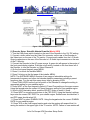
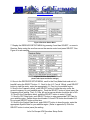
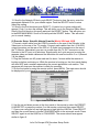
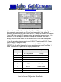
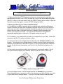
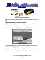
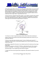
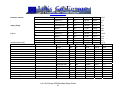
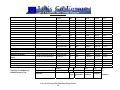
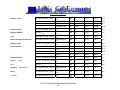
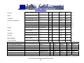
www.letsgo-europe.com
This handbook was written to help users setup their AFN Antenna and Decoder. Both
of these must be setup and configured correctly before you can receive AFN signals.
You will need:
- Internet access (or complete step one and download/print this guide for later use)
- Television
- Satellite dish
- AFN decoder
- Antenna cables (see step 4 below for appropriate cables and connectors)
- Magnetic compass
- Angle located / elevation guide / protractor (see step 3 below)
1. Authorizing your Decoder
You must Visit PowerVu Connect webpage to authorize your decoder. Enter in the TID
and UA numbers found on the back of your decoder and follow the instructions on the
screen to complete the authorization.
If Internet service is not available call AFRTS-BC 24 hours a day at (951) 413-2339,
DSN 348-1339 or AFRTS-HQ during normal working hours east coast time at (703)
428-0616, DSN 328-0616.
NOTE: AFN decoders must be reactivated every 3 years.
2. Setting up your Decoder
a) Find the appropriate satellite information (satellite name, azimuth, elevation). You
can find this information, along with the appropriate satellite name, in the back of this
guide starting on page 16.
b) Look up the applicable satellite for your region (ie Hotbird 6) and find the appropriate
band data, etc. in the list starting on page 28.
Once you have this information, follow the steps below, depending on your specific
decoder model. You will need the information you just found to complete the Decoder
and Antenna installation.
(1) 9223 model decoders
(2) 9234 model decoders
(3) 9834 and 9835 model decoders
Let’s Go Europe AFN Decoders Setup Guide
1
www.letsgo-europe.com
Figure 1 IRD (Decoder) Connection
(1) Decoder Setup: Scientific Atlanta PowerVu (Model 9223)
1. Turn the LNB power switch located on the rear of the Decoder to the 19V DC setting.
2. Connect a video cable from the Video Out connector on the rear of the Decoder to
the Video input on the rear of the TV monitor. Connect audio cables from the L-R Audio
Output connectors on the rear of the Decoder to L-R Audio Input connectors on the rear
of the TV Monitor.
3. Connect the Decoder to the AC power source. A green dot will appear in the center of
the front panel display window. Push the on/off switch, located on the front lower left of
the Decoder, to turn the Decoder on. Select Channel 0.
4. On the front panel keypad, press MENU.
5. Press 2, to unlock the installer MENU.
6. Press 9 to bring up the first page of the installer MENU.
NOTE: The INSTALLER MENU consists of two pages of selectable settings for
transponder frequency and other vital decoder specific parameters including a preset
frequency plan. You can exit this menu at any time by pressing VIEW.
7. Press CHAN UP/DN on the front left portion of the Decoder to change the setting to
appropriate setting for your satellite region.
8. Press NEXT on the front keypad to select L/C-band Freq setting on the menu screen.
Using the keypad enter the correct L/C-band frequency setting for your satellite region.
9. Scroll to the Polarization block, push the SELECT button to enter H (fixed).
10. Press NEXT to move the arrow down to the FEC RATE. Using the channel up/down
keys enter the correct FEC RATE for your satellite region. SatNet users should select ¾
and DTS users should select 2/3.
11. Press NEXT to select SYMBOL RATE. Using the keypad enter the correct SYMBOL
RATE for your satellite region.
12. Press YES on the front keypad section and note the system will respond that it is
saving the entries in the upper right of the TV monitor. NOTE: Failure to save entries will
Let’s Go Europe AFN Decoders Setup Guide
2
www.letsgo-europe.com
result in the system reverting to the factory default settings and the Decoder will not
authorize.
13 Double check the changes you made to page 1 of the installer MENU comparing the
settings with those listed in the PowerVu setup data for your satellite region.
14 Press USER to select page 2.
15 Press NEXT to select NETWORK ID.
16 Using the keypad enter the NETWORK ID for your satellite region.
17 Press YES to save the changes.
(2) Decoder Setup: Scientific Atlanta PowerVu (Model 9234)
1. Turn the LNB power switch located on the rear of the Decoder to ON.
2. If you are using a TV Monitor (a TV without ability to change channels), connect a
video cable from the Video Out connector on the rear of the IRD to the Video input on
the rear of the TV monitor. Connect audio cables from the L-R Audio Output connectors
on the rear of the Decoder to L-R Audio Input connectors on the rear of the TV Monitor.
3. If you are using a TV Receiver (a TV with ability to change channels), connect a
coaxial cable from the TV Out connector on the rear of the Decoder to the VHF input on
the TV. Select either TV channel 3 or 4 on the rear of the Decoder and select that
channel on your TV.
4. Connect the Decoder to a power source. Push the on/standby switch, located on the
front lower left of the Decoder, to turn the Decoder on.
5. Using the remote control, display the BSR MAIN MENU by pressing the Menu button.
See Figure 2 for an example.
Figure 2 BSR Main Menu
6. Display the RECEIVER STATUS MENU by pressing 2 and then SELECT, or move to
Receiver Status using the scroll arrows on the remote control and press SELECT. See
Figure 3 for an example.
Let’s Go Europe AFN Decoders Setup Guide
3
www.letsgo-europe.com
Figure 3 Receiver Status Menu
7. Display the RECEIVER SETUP MENU by pressing 3 and then SELECT, or move to
Receiver Setup using the scroll arrows on the remote control and press SELECT. See
Figure 4 for an example.
Figure 4 Receiver Setup Menu
(shown with Japan and Korea settings)
8. Once in the RECEIVER SETUP MENU, scroll to the Freq Mode block and set to Lband/#1 using the SELECT button. 11. Scroll to the L.O. Freq # 1 Block, push SELECT
button to clear the entry, enter the appropriate L.O. Freq for your satellite region.
9. Scroll to the Frequency block, push SELECT button to clear the entry, enter the
correct frequency for your satellite region. Push the SELECT button to store (save) the
Frequency block setting. The L.O. Freq. #2 and crossover blocks should be set to N/A.
10. Scroll to the Polarization block, push the SELECT button to enter H (fixed).
11. Scroll to FEC Rate block, push SELECT button to enter appropriate FEC Rate for
your satellite region. SatNet users should select 3/4 and DTS users should select 2/3.
Do not push SELECT button at this time.
12. Scroll to the Symbol Rate block, push SELECT button to clear the entry, enter the
appropriate Symbol Rate for your satellite region. (Refer to appendix D) Push the
SELECT button to store (save) the setting.
Let’s Go Europe AFN Decoders Setup Guide
4
www.letsgo-europe.com
13. Scroll to the Network ID block, push SELECT button to clear the entry, enter the
appropriate Network ID for your satellite region. Push the SELECT button to store
(save) the setting.
14. Scroll to the Exit block and push SELECT. (A yes/no box to store settings will
appear.) Push 1 to store the settings. This will return you to the Receiver Status Menu.
Scroll to the Exit block on this menu and push the SELECT button. This will return you
to the BSR MAIN MENU. Scroll to Exit and push the SELECT button. This will return
you to normal viewing.
(3) Decoder Setup: Scientific Atlanta PowerVu (Model 9834 and 9835)
1. Connect a video cable from the VIDEO connector on the rear of the Decoder to the
Video input on the rear of the TV monitor. Connect audio cables from the L-R AUDIO
output connectors on the rear of the IRD to L-R Audio Input connectors on the rear of
the TV Monitor. Alternatively you can run a cable from the TV OUT connector on the
Decoder to the RF input on a television. Signal quality isn’t quite as good as using the
separate video and audio cables and the television set must be tuned to 3 or 4 (channel
3 is the default).
2. Plug the Decoder into AC power and wait for about 1 minute while the receiver is
booting up before continuing on. While the receiver is booting up, the front panel display
will show APP and a number representing the current application code version. This
sequence will stop once the receiver is ready for operation.
3. On the front panel or using the remote control, press MENU. The main menu should
be displayed on your television or monitor’s screen as shown in figure 5.
Figure 5 9834 Decoder Main Menu
6. Use the up and down arrows on the front panel or the remote to select the PRESET
& LNB SETUP or press the number 2 on the remote control and then press SELECT.
7. Cursor over using the left and right arrows to high light the LNB Pwr. Press SELECT
and then the up and down to choose POLARISER which is the automatic mode. Press
SELECT again to set the LNB Pwr to POLARISER. The screen should now appear
similar to figure 6.
Let’s Go Europe AFN Decoders Setup Guide
5
www.letsgo-europe.com
Figure 6 Preset and LNB Setup Menu
8. Some Ku bank LNBs will have two local oscillator or LO frequencies. Use the up and
down arrows to cursor down to the LO Freq 1 and press select. Enter in the LO
frequency recorded from your LNB. Press SELECT to accept the numbers you entered.
If your LNB listed a second LO frequency enter that number in the same manner. You
can either use the arrow up or down key to change the numbers or enter them in
directly using the number buttons on the remote control. Press select to accept the
number.
9. Use the arrow keys to cursor over to the LO SELECT and choose XOVER. Press
SELECT again to accept this setting.
10. Use the left and right arrow key to cursor over to the ACTIVE setting and press
SELECT. Use the up and down arrow keys to select the proper preset from Table 1
below. Press SELECT again to set the proper preset into use.
Pre-set number
Signal
Region
1
AFRTS (Hotbird)
Europe
2
Not used
NA
3
AFRTS
Japan and Korea*
4
DTS
Pacific Ocean
5
DTS
Atlantic Ocean
6
DTS
Indian Ocean
7
AFRTS
Atlantic Ocean
8
AFRTS
Domestic US
9
DTS
Domestic US
Let’s Go Europe AFN Decoders Setup Guide
6
www.letsgo-europe.com
* Pre-set requires some modification see Appendix D.
Table 1 Decoder Pre-sets
11. Make sure that the ACTIVE pre-set matches your desired selection and then use
the arrow keys to cursor over to EXIT or press the 1 key on the remote and then press
SELECT to return to the main menu. Note the PRESET setting has no effect on how the
Decoder decodes the signal – only the ACTIVE setting has effect.
3. Placing and Aiming your Antenna (Satellite Dish)
a) You need two numbers to properly aim your satellite dish: Azimuth and Elevation.
Azimuth numbers are drawn from a magnetic compass and will tell you how far left or
right to aim your dish. Elevation numbers describe the angle up from the horizontal
horizon that you must tilt your dish (how far up, starting by aiming straight at the
horizon, you must turn your dish). You can find this information, along with the
appropriate satellite name, in the back of this guide starting on page 16
b) Go outside to your antenna site and hold your compass flat in your hand. Rotate the
compass to get the “N” (north) and pointer to align.
c) Locate the mark on the compass that corresponds to the azimuth number for your
location. This azimuth is the left/right direction in which you must place your antenna.
Satellites are located above the Earth’s equator, so you must generally aim toward the
equator (in the Northern Hemisphere, aim South, in the Southern Hemisphere, aim
North).
d) Point or aim your antenna roughly in the direction of your azimuth setting. Do not
worry about exactly aligning your antenna, because that will come in a later step.
Figure 7 Satellite Pointing Tools
e) Use your angle locator to find the angle listed as the elevation for your location.
Some antennas have an elevation scale on the antenna mount that will allow you to line
up your dish without an angle locator. If you don’t have an elevation scale and can’t
Let’s Go Europe AFN Decoders Setup Guide
7
www.letsgo-europe.com
locate an angle finder at your local hardware store, you can make your own using a
common protractor. See Figure 2 below.
Figure 8 Angle Finder using Common Protractor
f) Raise your satellite dish arm to approximately the elevation angle, using your angle
gauge for reference. This is the direction and elevation of your antenna. Sight down
your arm to ensure a clear path. Trees or buildings should not block your
antenna; otherwise your site will not be a suitable location. Trees will block
the signal so take into consideration their future growth.
g) At this point exact aiming is not important the dish is being pointed in a
general direction to allow for the installation of connection cables.
4. Connecting the Antenna (Satellite Dish) and Decoder
TIP: You should place the TV and decoder beside the antenna, or within view of the
antenna (through a window from the outside location) for aligning purposes. You can
place the TV and decoder box outside at the antenna location by running an extension
cord to that location.
a) Connect the antenna to the decoder box using RG-6 coaxial cable with “F” type
connectors. Thinner RG-59 coaxial cable can be used at lengths of 50ft or less. You
can purchase these items at you local Powerzone, or on the local market at an
electronics store.
Let’s Go Europe AFN Decoders Setup Guide
8
www.letsgo-europe.com
Figure 9 Antenna cable and connectors
Leave enough slack in the cables so that the dish may move back and forth and up and
down.
5. Making Adjustments and Locking on the Satellite
a) At this point you should have the antenna setup in the general direction of the
satellite and connected to the decoder, and have the decoder in turn connected to the
television. It is time to fully align your antenna to receive a television signal.
b) On the decoder, from the MAIN MENU cursor up to DISH SETUP and press select.
Figure 10 Dish Setup Menu
c) If the dish is aligned correctly you will see maximum indications on both SIGNAL
QUALITY and SIGNAL LEVEL and should hear a steady high pitched tone from the
television’s speaker. SIGNAL LOCK should display YES.
NOTE: if you ever see the Signal State change from No Lock to Lock + Sig, whatever
you do, do not change your antenna position. Lock + Sig means your antenna and
decoder are locked onto the AFN satellite.
Let’s Go Europe AFN Decoders Setup Guide
9
www.letsgo-europe.com
d) The green signal LED on the front of the IRD and the Signal Status menu are the first
and most reliable indicators of receiving the satellite signal. It is best to use the signal
status menu window for signal verification during the antenna tuning process. On the
9834 and 9835 the signal LED is located near the center of the display and will light
when the signal is locked in and authorized, blink when the signal is locked in but not
authorized, and not light when no signal has been found.
e) Now is the time to adjust the elevation angle on your antenna using the scale located
on the back of the antenna or use the protractor method if the antenna is not marked.
Note: when adjusting the elevation angle of an offset dish, subtract the manufacture’s
offset angle from the elevation angle provided for reference.
Figure 11 Look angle adjustment
You’ll have to do this if using the protractor method. Most offset dish manufacturers
supply a gauge on the antenna mount that automatically makes this correction for you
(see Figure 8 above).
f) Once you have the proper elevation angle, it’s time to find the exact azimuth. If
necessary, loosen the nuts on the antenna support pole so that the antenna can rotate
easily left and right.
g) Hold the compass flat in the palm of your hand away from the antenna and any large
metal object.
h) Rotate the compass so that the “N” (North) is under the dark point of the compass
pointer or arrowhead. Your compass is now aligned with the north and the marks
around the edge of the compass represents azimuth degrees.
i) Locate the mark on the compass that corresponds to the azimuth number for your site
location.
Let’s Go Europe AFN Decoders Setup Guide
10
www.letsgo-europe.com
j) Swing the antenna in the direction of your azimuth (compass) heading, use the LNB
that sticks out from the dish center as your pointer. Try to make this adjustment as
accurately as you possibly can. It usually helps to pick an object that is several
hundred feet away from your antenna that aligns with the antenna mounting pole and
your azimuth heading, and then to align your antenna with that object.
k) After making azimuth adjustments, to prevent the antenna from moving, lightly tighten
those bolts down. If you are lucky enough to have a locked signal at this point, exit from
the Installer/Receiver Setup Menu to the main menu and set the Decoder to a known
video channel. The Decoder will not authorize immediately, so give it a couple of
minutes to do so. If after a couple of minutes the Decoder does not authorize, check
the customer settings in the satellite listed for your region (repeat step 2 above) and see
step 7 below for troubleshooting. As indicated above, Lock + Sig is proof that your
antenna is locked on the satellite. All other problems are associated with the Decoder
setup or authorization in the AFRTS database.
6. Fine Tuning your Antenna
a) Perform this procedure only after getting Lock + Sig in the Installer or Receiver Setup
menu. If no Lock + Sig go to step 8 below.
b) Mark your antenna’s azimuth and elevation settings with a magic marker pen for
reference. This is done as precaution, just in case you totally loose the signal during the
fine-tuning phase.
c) Slowly tilt the antenna forward and backward (elevation) and set for maximum “Signal
Level” and “BER/Signal Quality” levels moving the antenna’s edge by just a half and
inch or less. Signal quality or BER is the most important to maximize. Remember, BER
of 0.0 E-2 is bad and 0.0 E-6 is perfect, and Signal Quality 1-10, with 10 being the best.
d) Do the same for azimuth, left and right again moving the dish in very slight amounts.
e) Repeat steps 2 and 3 at least two times each.
f) Tighten the bolts down with a wrench to prevent movement.
DONE? Need AFN Television Schedules? Get them online at:
http://www.letsgo-europe.com/Germany/military/AFN_television_schedule.html
7. Repeat Fine Tuning (if needed)
If the Signal State is not displaying Lock + Sig do the following:
Let’s Go Europe AFN Decoders Setup Guide
11
www.letsgo-europe.com
a) Check to see if the LNB Power switch on the back of the set is set to the ON position
for a 9234. For a 9223, the Decoder has three Power positions: 19, OFF, and 13/19 Volt
positions, do the following, for C-band users set it to the 19 Volt position, for Ku-band
users set it to the 13/19 Volt position. On the 9834 and 9835 the voltage is controlled by
the software in the menu PRESET & LNB SETUP.
b) Also, ensure your antenna is polarized correctly for the signal you intend to receive.
Note: For Ku-band users (direct to home customers in Europe, Japan and Korea) the
receiver voltage can switch the antenna polarization from vertical to horizontal within the
receiver setup menu (13 Vertical-19 Horizontal).
c) If this was your problem, the green signal light on front of the Decoder will illuminate.
Go to the Receiver Setup or Installer Menu and check to see if the No Signal state has
change to Sig+Lock.
d) If you have Sig+Lock, go back to Step 5 and following those instructions.
e) If this was not your problem, it is time again to check the antenna position; perform
the following:
- Check the azimuth and elevation and reposition as needed. Use very small
movements up and down, left and right. Remember that small adjustments will move
you among satellites. You should be moving the dish one quarter to a half and inch
measured at the edge at a time. If the signal level increases significantly with No lock +
Signal, you are on the wrong satellite or the setup parameters are wrong.
- Remember at any time during the following procedures you get a locked signal
(Lock+Sig) stop and mark the antenna’s azimuth and elevation positions. If yes go back
to “Peaking the Antenna” if no proceed to the next step.
- The following is a slow process but will result in aligning your antenna.
- Loosen antenna-mounting bolts so that you can move the antenna’s azimuth (east and
west).
- While monitoring the Signal State (No Lock) slowly move the antenna from east to
west. Again, if the signal state ever changes to Lock+Sig, stop and lock the antenna in
that position and perform “Peaking the Antenna”.
- This is a long and time-consuming process to follow and adjustments must be made in
slow, small increments. Reset the antenna’s elevation by repositioning by less than one
degree, tilting it in ½ inch increments, locking it down and moving it slowly, east to west.
Let’s Go Europe AFN Decoders Setup Guide
12
www.letsgo-europe.com
- Repeat Step last two steps until you have a LOCKED (Lock+Sig) signal.
- Once you obtain a locked signal, mark the antenna’s azimuth and elevation with a
permanent marker for future reference.
8. Troubleshooting Guide
Satellite integrated receiver decoder will not turn on.
(1) Check to see if the receiver is plugged in to the wall jack.
(2) Try plugging the receiver into a different electrical outlet. Be sure you’re not plugged
into a “half hot” or “switched” outlet controlled with a light switch.
(3) Plug your TV into the same outlet and see if it will power on.
(4) Make sure the problem is not with the receiver. Turn on the receiver both from the
front panel and with the remote.
(5) Check the fuse box circuit breaker.
I cannot set the receiver to the on-screen menu.
(1) Check to see if your TV is tuned to the correct channel either channel 3 (default) or 4
and select the same on the back of the receiver.
(2) Check to see if you are using the correct connections from the Receiver to the TV.
Are you using the RF (To TV) connection and connected to the “from antenna on the
TV”. Are you connected to the Video output from the receiver, to the video input on the
TV/monitor.
(3) If you are using the RF connection from the receiver to the TV, tune to channel 3 or
4.
(4) Turn the receiver on from the remote or the front panel.
(5) In the receiver setup menu select NTSC.
I cannot pick up the satellite signal
(1) Have you gotten your receiver authorized?
(2) Check that all signal connections from antenna, receiver, and TV are correct.
Let’s Go Europe AFN Decoders Setup Guide
13
www.letsgo-europe.com
(3) Make sure there are no obstructions blocking the antenna’s view to the satellite.
Always stand behind the antenna, not in front while checking. Vegetation like bushes
and trees will block the satellite signal.
(4) Check that the antenna is set to the correct polarity, for example, horizontal, vertical,
left hand circular or right hand circular.
(5) Check the antenna azimuth and elevation settings, if wrong see “Antenna Pointing”.
(6) Tune the receiver to the “Receiver Setup Menu” on the 9234 and 9834, the “Installer
Menu” on the 9223, or the “Dish Setup” and the 9834 and 9835 receiver model. If the
signal indicator reads Sig+Lock, check the following for your location and service. If all
of the settings below are correct; chances are good that your decoder isn’t authorized in
the AFRTS decoder database; call for authorization – see step 1 of this guide above.
Use the list on page 28 to check the parameters listed below. On the model 9834
ensure that the proper pre-set setting is being used for your region.
a. Network ID
b. FEC Rate
c. Frequency
d. Band
e. L.O.
f. Polarization
g. Symbol Rate
h. Video Standard is (NTSC)
(7) If the signal indicator in the “Receiver Menu” reads No Signal check the cable from
the antenna to the Receiver.
(8) “Reboot” your IRD. Turn off the IRD using the remote control and then unplug it from
the electrical power. Wait a minute and then plug the IRD back in and turn it on.
(9) Rarely you might be attempting to receive the signal during either a sun outage or a
signal outage caused by a technical problem at the up link site. These outages would
affect an entire region at once so your neighbors and other service members at your
command would have also lost signal. An easy check is to see if the signal is available
at another receiver in your same location. A sun outage lasts only 10 to 15 minutes.
Sun outages over the United States can affect signals in elsewhere in the world.
I was receiving the satellite signal but it comes and goes or I get a lot of freeze
frames and digital artifacts.
This is the sign of a weak signal and can usually be traced to one of the following
problems:
Let’s Go Europe AFN Decoders Setup Guide
14
www.letsgo-europe.com
(1) Poor connection from the Antenna to the Receiver. Wiggle the connections to see if
you can get the signal to intermit from Loss of Signal to Freeze-Frames. If so, redo or
replace connectors.
(2) Antenna is not peaked for best signal strength or is too small for your area. See the
section of this chapter on signal peaking. Your dish should be at least the same size as
other’s who are watching AFRTS.
(3) LNB does not meet specifications. This typically happens with a new LNB that has
replaced a failed on or one from a brand new installation. Heat and cold will often cause
a marginal LNB to lose signal.
(4) Poor quality cable or connectors in use or impedance mismatch. Make sure that you
are using the proper RF cabling between the LNB and the receiver. Computer network
cable is the wrong electrical impedance and will cause signal loss.
(5) Signal level input to the IRD is too high; optimum input is –42 dBm. This is very rare.
(6) Antenna is not stable; wind moves or shakes the antenna excessively. Extreme
weather will cause the satellite dish to move off the satellite’s position.
(7) Terrestrial Interference. Typically caused by radio transmitters located in front of the
dish.
(8) This could be caused by a regional sun outage where the sun passes directly behind
the satellite. At certain times of year, approximately one month either side of the spring
and autumn equinoxes, there may be a conjunction of the sun and satellite positions.
Depending upon the size of the earth station antenna, such events can lead to a serious
impairment of the space-earth link. These outages typically last only a few minutes at a
time once a day with a normal worse case outage of about ten to fifteen minutes.
Outages will affect each link in multi-hop circuits. For example viewers in Europe or the
Indian Ocean area would be affected by an outage of first, the Atlantic satellite and then
secondly, of the actual satellite feeding their antenna. Antennas should not be adjusted
or re-pointed at these lost-of-signal times. The viewer should wait out the outage until
the sun finishes passing directly behind the satellite.
Let’s Go Europe AFN Decoders Setup Guide
15
www.letsgo-europe.com
Dish Pointing Data (using magnetic north)
AFRICA, MIDDLE EAST, SW
ASIA Country, City
Afghanistan, Kabul
LAT LOG Magnetic
Variation:
34.35N 69.12E MV 13.5E
Algeria, Alger
28.00N
3.00E
“
“
“
Azerbaijan, Baku
Bahrain, Manama
“
“
“
Bangladesh, Dhaka
Cameroon, Yaounde
“
“
British Indian Ocean Territory,
Diego Garcia
“
Djibouti, Djibouti
“
“
Egypt, Cairo
MV:2.01W
40.23 N 39.51 E MV: 4.95
E
26.13N 50.35 E MV:2.12E
24.00N 90.25E MV: 56W
6.00 N 12.00 E MV: 2.79 W
7.26 S 72.37 E MV: 7.59W
11.30 N 43.00 E MV: 1.07
E
30.50 N 31.00 E MV: 2.61
E
Satellite
Type
Polarization
HOTBIRDS 6 & 7a
INTELSAT 906
KU
C
V
LHC
INTELSAT 906
C
HOTBIRDS 6 & 7a
INTELSAT 10-02
NSS-7
HOTBIRDS 6 & 7a
13.0E
64.1E
Mag
Azimuth:
246.8
135.1
19.2
9.4
LHC
64.0 E
106.59
17.03
KU
C
C
KU
V
RHC
LHC
13.0 E
359 E
338.0 E
13.0 E
160.5
190.48
225.8
213.2
55.5
57.02
47.3
36.1
INTELSAT 906
HOTBIRDS 6 & 7a
INTELSAT 10-02
NSS-802
INTELSAT 906
INTELSAT 906
NSS-802
INTELSAT 906
C
KU
C
C
C
C
C
C
LHC
V
RHC
LHC
LHC
LHC
LHC
LHC
64.0 E
13.0 E
359 E
338.0 E
64.0 E
64.0 E
338.0 E
64.0 E
149.01
237.9
248.48
259.9
231.05
96.6
263.4
318.25
55.88
38.8
26.32
7.2
49.37
25.0
50.0
76.99
V
Location:
Elevation:
INTELSAT 10-02
INTELSAT 906
C
C
RHC
LHC
359 E
64.0E
279.75
114.91
7.88
61.33
NSS-7
INTELSAT 10-02
INTELSAT 906
C
C
C
LHC
RHC
LHC
338.0 E
359 E
64.0E
263.4
257.46
125.40
16.1
38.02
39.58
Let’s Go Europe AFN Decoders Setup Guide
16
www.letsgo-europe.com
“
“
“
India, New Delhi
Ivory Coast, Abidjan
Iraq, Baghdad
“
Basra
28.36 N 77.12 E MV: 0.51
E
5.19 N 4.02
MV: 8.54
WW
33.20 N 44.26E MV: 4.81
30.5 N 47.75 E MV: 5.12
Mosul
36.19 N 43.9 E MV: 4.87
Israel, Jerusalem
“
“
“
Tel Aviv
31.46 N 35.14 E MV: 2.76
“
“
“
Kenya, Nairobi
“
“
Kuwait, Kuwait City
“
“
“
“
32.05 N 34.48 E MV: 3.13
E
1.17 S 36.49 E MV:0.1W
29.30 N 47.45 E MV: 2.55E
HOTBIRDS 6 & 7a
INTELSAT 10-02
NSS-7
INTELSAT 906
KU
C
C
C
NSS-7
C
HOTBIRDS 6 & 7a
NSS-7
HOTBIRDS 6 & 7a
V
RHC
LHC
LHC
LHC
13.0E
359 E
338.0 E
64.0 E
209.9
228.31
246.3
205.62
49.4
40.33
23.2
53.87
338.0 E
260.7
68.1
HOTBIRDS 6 & 7a
NSS-7
HOTBIRDS 6 & 7a
INTELSAT 10-02
NSS-7
INTELSAT 906
INTELSAT 906
Ku
C
Ku
C
Ku
C
KU
C
C
C
C
V
LHC
V
LHC
V
LHC
V
RHC
LHC
LHC
LHC
13.0E
338 E
13.0E
338.0 E
13.0E
338.0 E
13.0 E
359 E
338.0 E
64.0 E
64.0 E
224.6
253.1
197.8
235.2
207.4
137.5
222.2
231.69
248.3
130.68
130.03
38.7
11.0
33.5
15.8
35.0
32.9
14.1
36.57
19.4
41.87
40.97
HOTBIRDS 6 & 7a
INTELSAT 10-02
NSS-7
INTELSAT 906
NSS-7
INTELSAT 10-02
INTELSAT 906
KU
C
C
C
C
C
C
V
RHC
LHC
LHC
LHC
RHC
LHC
13.0 E
359 E
338.0 E
64.0 E
338.0 E
359 E
64.0 E
213.5
230.22
247.7
87.90
270.6
271.67
146.19
46.0
36.68
19.7
57.85
23.5
46.52
51.29
HOTBIRDS 6 & 7a
INTELSAT 10-02
KU
C
13.0 E
359 E
231.8
244.01
39.3
27.64
V
RHC
Let’s Go Europe AFN Decoders Setup Guide
17
www.letsgo-europe.com
“
“
Malawi, Banjul
“
“
Mali, Bamako
“
“
Morocco, Rabat
“
“
Mozambique, Maputo
“
“
Pakistan, Islamabad
Saudi Arabia Jiddah (Jeddah)
“
“
“
KKMC
“
“
“
Saudi Arabia (Continued)
Riyadh
“
13.28 N 16.39 W
MV:11.28W
“
12.39 N 8.00 W MV: 7.15
W
34.02 N 6.51 W MV: 4.78
W
26.00 S 32.25 E MV:17.08
W
33.42 N 73.10 E MV: 1.59
E
21.30 N 39.12 E MV: 2.02
E
NSS-802
NSS-802
C
C
LHC
LHC
338.0 E
338.0 E
256.79
212.55
9.68
73.30
INTELSAT 906
INTELSAT 906
C
C
LHC
LHC
64.0 E
64.0 E
103.51
101.14
0.66
8.98
NSS-7
INTELSAT 10-02
HOTBIRDS 6 & 7a
C
KU
KU
LHC
RHC
V
338.0 E
359 E
13.0 E
235.1
157.37
151.1
68.2
73.31
45.3
INTELSAT 10-02
NSS-7
INTELSAT 906
C
C
C
RHC
LHC
LHC
359 E
338.0
64.0 E
175.00
209.7
71.77
50.02
47.1
43.55
INTELSAT 10-02
NSS-7
INTELSAT 906
C
C
C
RHC
LHC
LHC
359 E
338.0 E
64.0 E
320.85
305.5
194.63
42.32
23.7
49.92
INTELSAT 906
C
LHC
64.0 E
124.93
51.65
27.80 N 45.50 E MV:2.37 E
HOTBIRDS 6 & 7a
NSS-7
INTELSAT 10-02
INTELSAT 906
HOTBIRDS 6 & 7a
NSS-7
INTELSAT 10-02
24.39N 46.43 E MV: 2.13E
INTELSAT 906
HOTBIRDS 6 & 7a
KU
C
C
C
KU
C
C
V
LHC
RHC
LHC
V
LHC
RHC
13.0 E
338.0 E
359 E
64.0 E
13.0 E
338.0 E
359 E
231.1
256.3
244.6
140.6
231.1
256.4
243.8
51.4
18.5
38.66
51.1
41.8
11.3
30.0
C
LHC
64.0 E
138.9
54.75
KU
V
13.0 E
235.8
43.1
Let’s Go Europe AFN Decoders Setup Guide
18
www.letsgo-europe.com
“
“
Tabuk
“
“
“
South Africa, Capetown
“
“
Pretoria
“
“
Tunisia, Tunis
“
“
“
Turkey (See Europe table)
Uganda, Kampala
“
United Arab Emirates (UAE),
Abu Dhabi
“
“
Yemen, Sanaa
“
“
“
28.23 N 36.35E MV: 2.76 E
33.55 S 18.22 E MV:
22.00W
25.45 S 28.10 E 14.29 W
36.48 N 10.11 E MV: 0.44
E
INTELSAT 10-02
NSS-7
INTELSAT 906
HOTBIRDS 6 & 7a
INTELSAT 10-02
NSS-7
INTELSAT 906
INTELSAT 10-02
NSS-7
INTELSAT 906
INTELSAT 10-02
NSS-7
INTELSAT 906
HOTBIRDS 6 & 7a
INTELSAT 10-02
NSS-7
0.19 N 32.25 E MV: 0.28
24.28 N 54.22 E MV: 1.45
E
15.23 N 44.12 E MV:1.28 E
INTELSAT 906
NSS-7
INTELSAT 906
HOTBIRDS 6 & 7a
INTELSAT 10-02
HOTBIRDS 6 & 7a
INTELSAT 10-02
NSS-7
INTELSAT 906
C
C
C
KU
C
C
C
RHC
LHC
LHC
V
RHC
LHC
LHC
359 E
338.0 E
64.0 E
13.0 E
359 E
338.0 E
64.0 E
247.1
258.5
129.32
219.6
235.45
250.9
83.73
30.5
11.0
45.18
48.2
37.58
19.3
27.86
C
C
C
C
C
C
RHC
LHC
LHC
LHC
LHC
LHC
359 E
338.0 E
64.0 E
359 E
338.0
64.0 E
349.75
327.0
73.59
321.96
305.9
113.01
45.86
32.2
40.40
46.07
27.7
20.13
KU
C
C
V
RHC
LHC
13.0 E
359 E
338.0 E
174.4
197.84
225.8
47.6
46.07
35.9
C
C
C
LHC
LHC
LHC
64.0 E
338.0 E
64.0 E
90.03
269.5
155.81
53.03
28.1
59.54
KU
C
KU
C
C
C
V
RHC
V
RHC
LHC
LHC
13.0 E
359 E
13.0 E
359 E
338.0 E
64.0 E
243.4
252.61
244.9
254.06
261.8
124.72
36.3
23.35
50.1
35.87
14.6
60.93
Let’s Go Europe AFN Decoders Setup Guide
19
www.letsgo-europe.com
AMERICAS Country, City
Columbia, Bogota
“
Cuba, Guantanamo Bay
“
Ecuador, Quito
Honduras, Soto Cano AB
Puerto Rico, Roosevelt Roads
LAT LOG Magnetic
Variation:
Satellite
14.66 N 74.12 W MV: 5.0 W
INTELSAT 10-02
NSS-7
C
C
19.93 N 75.12 W MV: 5.72
W
NSS-7
0.13 S 78.30 W MV: 1.17 E
14.37 N 87.60W MV:1.76 E
18.23 N 65.65 W
MV:12.87W
“
“
Venezuela, Caracas
“
ASIA Country, City
Brunei, Bandar Seri Begawan
Burma, Rangoon
China
Beijing
Shanghai
“
10.66 N 66.82 W MV: 9.87
W
LAT LOG Magnetic
Variation:
4.95 N 114.6 E MV:0.32E
16.47 N 96.10 E MV :0.78 E
39.55 N 166.25 E MV:5.82
W
31.01 N 121.30E MV: 4.63
W
Type
Polarization:
Location:
Mag
Azimuth:
Elevation:
RHC
LHC
359 E
338.0 E
99.40
108.7
7.70
28.8
C
LHC
338.0 E
112.0
26.6
IA-8
NSS-7
NSS-7
IA-8
C
C
C
C
H
LHC
LHC
H
89.0 E
338.0 E
338.0 E
89.0
224.2
91.6
103.9
222.4
61.8
25.9
24.6
69.1
INTELSAT 10-02
C
RHC
359 E
111.30
15.62
NSS-7
IA-8
C
C
LHC
H
338.0 E
89.0 E
121.2
247.5
36.4
55.8
INTELSAT 10-02
C
RHC
359 E
104.62
15.36
NSS-7
C
LHC
338.0 E
Satellite
NSS-5
INTELSAT 906
Type
C
C
Polarization:
LHC
LHC
Location:
177 W
64.0 E
112.0
37.3
Mag
Azimuth: Elevation:
91.6
13.0
245.9
48.7
POR DTS
C
LHC
180.0 E
158.0
42.1
NSS-5
NSS-6
C
Ku
LHC
VP
177 W
95 E
110.8
216.9
9.1
39.2
POR DTS
C
LHC
180.0 E
112.2
18.2
NSS-5
NSS-6
INTELSAT 906
C
Ku
C
LHC
VP
LHC
177 W
95 E
64.0 E
110.3
228.6
256.4
15.6
44.0
19.5
Let’s Go Europe AFN Decoders Setup Guide
20
www.letsgo-europe.com
Indonesia, Jakarta
“
“
Japan, Atsugi
Iwakuni
“
“
Misawa (Misawa AB)
“
Okinawa (Camp Butler)
“
“
Sasebo
“
“
Tokyo (Yokota AB)
“
Johnston Island Atoll
Korea, Kwangju
“
6.10 S 106.48 E MV: 0.12W
35.27 N 139.27 E MV: 7.39
W
34.15 N 132.24 E MV: 7.27
W
INTELSAT 906
POR DTS
NSS-5
C
C
C
LHC
LHC
LHC
64.0 E
180.0 E
177 W
276.74
88.32
88.3
40.57
7.77
4.7
INTELSAT 701
C
LHC
180.0 E
131.2
30.8
NSS-5
NSS-6
C
Ku
LHC
VP
177 W
95 E
128.5
246.7
28.5
28.1
POR DTS
C
LHC
180.0 E
117.0
25.99
C
Ku
C
C
LHC
VP
LHC
LHC
LHC
VP
LHC
LHC
VP
LHC
LHC
LHC
VP
LHC
LHC
LHC
VP
LHC
LHC
LHC
177 W
95 E
64.0 E
180.0 E
177 W
97 E
180.0 E
177 W
95 E
64.0 E
180.0 E
177 W
95 E
64.0 E
180.0 E
177 W
97 E
180.0E
180.0 E
177 W
121.7
240.0
257.3
129.2
135.0
246.8
113.24
111.1
239.9
257.6
114.4
119.0
238.5
256.1
124.2
129.0
246.7
202.48
113.1
117.6
23.6
34.0
9.4
28.70
26.8
23.6
24.48
22.7
42.5
15.0
24.4
22.0
36.5
11.7
30.5
28.3
27.8
66.94
21.0
18.6
NSS-5
NSS-6
INTELSAT 906
40.68 N 141.36E MV:8.48 W POR DTS
NSS-5
NSS-6
26.31 N 127.79 E MV: 4.28 W POR DTS
NSS-5
NSS-6
INTELSAT 906
33.17 N 129.72 E MV: 6.01 W POR DTS
NSS-5
NSS-6
INTELSAT 906
35.75 N 139.34 E MV:6.50 W POR DTS
NSS-5
NSS-6
16.73 N 169.52 W MV:1024 E POR DTS
35.09 N 126.54 E MV:6.69 W POR DTS
NSS-5
C
Ku
C
C
Ku
C
C
C
Ku
C
C
C
Ku
C
C
C
Let’s Go Europe AFN Decoders Setup Guide
21
www.letsgo-europe.com
1.22 N 103.48 E MV:0.43 W
NSS-6
INTELSAT 906
POR DTS
NSS-5
NSS-6
INTELSAT 906
POR DTS
NSS-5
NSS-6
INTELSAT 906
POR DTS
NSS-5
NSS-6
INTELSAT 906
NSS-5
NSS-5
NSS-6
INTELSAT 906
Ku
C
C
C
Ku
C
C
C
Ku
C
C
C
Ku
C
C
C
Ku
C
VP
LHC
LHC
LHC
VP
LHC
LHC
LHC
VP
LHC
LHC
LHC
VP
LHC
LHC
LHC
VP
LHC
95 E
64.0 E
180.0 E
177 W
95 E
64.0 E
180.0 E
177 W
95 E
64.0 E
180.0 E
177 W
95E
64.0 E
177 W
177 W
95 E
64.0 E
233.6
260.06
121.68
119.6
233.5
260.16
121.79
120.0
233.3
259.83
121.78
120.2
236.0
261.19
96.0
100.2
224.5
268.95
37.3
13.72
20.58
18.3
35.5
12.73
20.31
18.0
35.1
12.61
22.34
20.0
35.4
11.85
12.6
11.0
56.1
44.29
8.73 N 167.74 E MV:8.65 E
POR DTS
C
LHC
180.0 E
116.29
72.36
14.55 N 121.0 E MV :1.27 W
NSS-5
NSS-5
“
Osan (Osan AB)
“
37.08 N 127.03 E MV:7.22 W
“
Seoul
“
37.60 N 126.98 E MV: 7.12 W
“
Taegu (AFKN)
“
35.84 N 128.59 E MV:6.73
“
Guam, Agana
Hong Kong
“
Malaysia, Singapore
Marshall Islands, Kwajalein
Island
“
Philippines, Manila
13.4N 114.75 E MV:0.7 W
22.28 N 114.2 E MV:1.88 W
Taiwan, Taipei
25.0 N 121.5 E MV :3.43 W
Viet Nam, Ho Chi Minh City
EUROPE Country, City
10.7 N 106.7 E MV:0.12W
LAT LOG Magnetic
Variation:
NSS-5
NSS-6
NSS-5
Satellite: Type:
C
C
Ku
C
Ku
C
Type
LHC
LHC
VP
LHC
VP
LHC
Polarizatio
n:
Let’s Go Europe AFN Decoders Setup Guide
22
177 W
177 W
95 E
177 W
95 E
177 W
Location:
110.7
98.9
244.0
106.4
233.1
92.7
Mag
Azimuth:
69.4
18.8
55.5
17.3
48.4
4.8
Elevation:
www.letsgo-europe.com
Albania, Tirania
41.20N 19.49E MV: 1.92 E
“
“
“
Austria, Vienna
48.12N 16.22E MV: 2.15 E
Belgium, SHAPE
50.50N
Mons
50.58 N 4.05 E MV: 1.94 W
Bosnia Herzegovina, Sarajevo
43.52 N 18.25 E MV: 2.14 E
Bulgaria, Sofia
42.41N
23.19E MV: 2.91 E
Cyprus, Nicosia
35.10N
33.22E MV: 3.08 E
04.20E MV: 1.95
W
“
“
“
Finland, Helsinki
60.10N
24.58E MV: 6.23 E
Istres
43.31N
04.59E MV:1.37 W
48.52N
02.20E MV: 2.46
w
France
Paris
Germany
Baumholder
49.37N 07.20E MV: 1.23 W
Bitburg
49.58N 06.31E MV: 1.15 W
Frankfurt
50.13N 8.68 E MV: 0.46 W
HOTBIRDS 6 &
7a
INTELSAT 10-02
NSS-7
INTELSAT 906
HOTBIRDS 6 &
7a
HOTBIRDS 6 &
7a
HOTBIRDS 6 &
7a
HOTBIRDS 6 &
7a
HOTBIRDS 6 &
7a
INTELSAT 906
HOTBIRDS 6 &
7a
INTELSAT 10-02
NSS-7
HOTBIRDS 6 &
7a
HOTBIRDS 6 &
7a
HOTBIRDS 6 &
7a
HOTBIRDS 6 &
7a
HOTBIRDS 6 &
7a
HOTBIRDS 6 &
7a
KU
V
13.0 E
187.3
41.9
C
C
C
RHC
LHC
LHC
359 E
338.0 E
64.0 E
207.65
230.8
121.90
37.97
26.5
24.55
KU
V
13.0 E
182.1
34.7
KU
V
13.0 E
170.0
31.5
KU
V
13.0 E
169.9
31.4
KU
V
13.0 E
185.2
39.5
KU
V
13.0 E
191.8
40.0
C
LHC
64.0 E
130.91
37.80
KU
V
13.0E
209.3
43.9
C
C
RHC
LHC
359 E
338.0 E
226.71
244.9
35.50
19.6
KU
V
13.0 E
187.2
21.1
KU
V
13.0 E
168.5
39.3
KU
V
13.0 E
165.9
38.6
KU
V
13.0 E
172.7
33.1
KU
V
13.0 E
171.8
32.8
KU
V
13.0 E
174.2
32.4
Let’s Go Europe AFN Decoders Setup Guide
23
www.letsgo-europe.com
Garmisch
47.29N 11.05E MV: 0.17 E
Hannau
50.08N 08.55E MV: 0.44W
Heidelberg
49.25N 08.43E MV: 0.47 W
Kaiserlautern (Ramstein)
49.26N 07.46E MV: 1.25 W
“
“
“
Stuttgart
48.46N 09.11E MV: 0.45 W
Vilseck
49.37N 11.48E
Wiesbaden
50.05N 08.14E MV: 0.37 E
Wurzburg
49.48N 09.56E MV: 0.64 E
Greece Athens
37.59N 23.44E
(Crete) Souda Bay
35.29N 24.42E MV: 2.44 E
“
(Crete) Souda Bay (continued)
“
Greenland, Thule
Hungary, Budapest
Iceland, Keflavik
“
“
Ireland, Dublin
76.34N 68.47E MV: 68.33 W
47.30N 19.05E MV: 2.28 E
63.96N 22.60W MV: 20.60W
53.20N 06.15W MV: 7.70 W
HOTBIRDS 6 &
7a
HOTBIRDS 6 &
7a
HOTBIRDS 6 &
7a
HOTBIRDS 6 &
7a
INTELSAT 10-02
NSS-7
INTELSAT 906
HOTBIRDS 6 &
7a
HOTBIRDS 6 &
7a
HOTBIRDS 6 &
7a
HOTBIRDS 6 &
7a
HOTBIRDS 6 &
7a
HOTBIRDS 6 &
7a
INTELSAT 10-02
NSS-7
INTELSAT 906
GE 1
HOTBIRDS 6 & 7a
HOTBIRDS 6 & 7a
INTELSAT 10-02
NSS-7
HOTBIRDS 6 & 7a
KU
V
13.0 E
176.4
35.6
KU
V
13.0 E
196.1
32.4
KU
V
13.0 E
173.9
33.3
KU
V
13.0 E
173.9
33.3
C
C
C
RHC
LHC
LHC
359 E
338.0
64.0 E
192.36
217.6
117.85
32.91
26.5
12.61
KU
V
13.0 E
174.5
34.2
KU
V
13.0 E
KU
V
13.0 E
173.7
32.4
KU
V
13.0 E
175.0
33.2
KU
V
13.0 E
194.1
45.1
KU
V
13.0 E
196.7
47.2
C
C
C
C
KU
KU
C
C
KU
Let’s Go Europe AFN Decoders Setup Guide
24
RHC
LHC
LHC
V
V
V
RHC
LHC
V
359 E
338.0 E
64.0 E
103.0 W
13.0 E
13.0 E
359 E
338.0 E
13.0 E
216.50
238.6
122.41
283.63
185.4
160.6
176.82
198.3
162.6
40.89
26.5
31.24
2.53
35.3
12.4
15.72
17.8
26.7
www.letsgo-europe.com
Italy Aviano
La Maddalena
Livorno (Pisa)
“
“
“
Naples
“
“
“
Sicily AFN-S Station Sigonella
“
“
“
Vicenza
Lithuania, Vilnius
Madeconia, (Former Yugoslav
Republic), Skopje
Netherlands The Hague
Maastricht
Norway Oslo
Stavanger
Poland, Warsaw
Portugal, Azores (Lajes Field)
“
“
Portugal (continued), Lisbon
“
“
46.04N 12.36E MV: 1.00 E
41.13N 09.24E MV: 0.22 W
43.33N 10.19E MV: 0.30 E
40.50N 14.13E MV: 1.31 E
37.43N 14.97E MV: 1.01 E
45.33N 11.33E MV: 0.13 E
54.41N 25.19E MV: 4.85 E
42.00N 21.29E MV: 2.30 E
52.05N 04.18E MV: 2.14 W
50.52N 05.43E MV: 2.10 W
59.55N 10.45E MV: 0.51 W
58.58N 05.45E MV: 3.35 W
52.13N 21.02E MV: 3.42 E
38.30N 28.00W MV: 12.92 W
38.43N 09.08W MV: 5.72 W
HOTBIRDS 6 & 7a
HOTBIRDS 6 & 7a
HOTBIRDS 6 & 7a
INTELSAT 10-02
NSS-7
INTELSAT 906
HOTBIRDS 6 & 7a
INTELSAT 10-02
NSS-7
INTELSAT 906
HOTBIRDS 6 & 7a
INTELSAT 10-02
NSS-7
INTELSAT 906
HOTBIRDS 6 & 7a
HOTBIRDS 6 & 7a
HOTBIRDS 6 & 7a
KU
KU
KU
C
C
C
KU
C
C
C
KU
C
C
C
KU
KU
KU
V
V
V
RHC
LHC
LHC
V
RHC
LHC
LHC
V
RHC
LHC
LHC
V
V
V
13.0 E
13.0 E
13.0 E
359 E
338.0 E
64.0 E
13.0 E
359 E
338.0 E
64.0 E
13.0 E
359 E
338.0 E
64.0 E
13.0 E
13.0 E
13.0 E
177.8
173.7
175.1
195.95
221.7
116.66
180.2
202.41
226.7
117.82
181.7
204.21
229.5
116.82
176.6
189.7
189.4
37.0
42.3
39.9
38.35
30.5
17.10
43.2
40.74
30.4
21.91
46.6
43.47
32.0
23.40
37.8
26.9
40.8
HOTBIRDS 6 & 7a
HOTBIRDS 6 & 7a
HOTBIRDS 6 & 7a
HOTBIRDS 6 & 7a
HOTBIRDS 6 & 7a
HOTBIRDS 6 & 7a
INTELSAT 10-02
NSS-7
HOTBIRDS 6 & 7
INTELSAT 10-02
NSS-7
KU
KU
KU
KU
KU
KU
C
C
KU
C
C
V
V
V
V
V
V
RHC
LHC
V
RHC
LHC
13.0 E
13.0 E
13.0 E
13.0 E
13.0 E
13.0 E
359 E
338.0 E
13.0 E
359 E
338.0 E
170.5
171.2
177.0
171.8
186.4
137.6
154.88
184.4
151.3
172.55
204.6
29.9
31.7
22.4
22.9
29.9
28.7
37.56
45.2
39.9
44.37
43.5
Let’s Go Europe AFN Decoders Setup Guide
25
www.letsgo-europe.com
Romania, Bucharest
Spain, Madrid
Moron (Moron de la Frontiera)
Rota
“
“
“
Sweden, Stockholm
Switzerland, Geneva
Turkey, Adana
Adara
Incirlik
“
“
“
Izmir
“
“
“
Ukraine, Kiev
“
“
“
United Kingdom, Cambridge
London
Reading
“
“
44.26N 26.06E MV: 3.98 E
40.24N 03.41W MV: 3.70 W
37.08N 05.27W MV: 4.21 W
36.37N 06.21W MV: 5.01 W
59.20N 18.03E MV: 3.21 E
46.12 N 6.09 E MV: 0.77 W
37.01N 35.18E MV: 3.47 E
39.56N 32.52E MV: 3.61 E
37.00 N 35.83 E MV: 3.40 E
38.25N 27.09E MV: 3.08 E
50.50 N 30.50 E MV: 5.76 E
52.13N 00.80E MV: 3.92 W
51.30N 00.07W MV:4.64 W
51.47N 0.98 W MV: 4.56 W
HOTBIRDS 6 & 7a
KU
V
HOTBIRDS 6 & 7a
KU
V
HOTBIRDS 6 & 7a
KU
V
HOTBIRDS 6 & 7a
KU
V
INTELSAT 906
C
LHC
INTELSAT 10-02
C
RHC
NSS-7
C
LHC
HOTBIRDS 6 & 7a
KU
V
HOTBIRDS 6 & 7a
KU
V
HOTBIRDS 6 & 7a
KU
V
HOTBIRDS 6 & 7a
KU
V
HOTBIRDS 6 & 7a
KU
V
INTELSAT 10-02
C
RHC
NSS-7
C
LHC
INTELSAT 906
C
LHC
HOTBIRDS 6 & 7a
KU
V
INTELSAT 10-02
C
RHC
NSS-7
C
LHC
INTELSAT 906
C
LHC
HOTBIRDS 6 & 7a
KU
V
INTELSAT 10-02
C
RHC
NSS-7
C
LHC
INTELSAT 906
C
LHC
HOTBIRDS 6 & 7a
KU
V
HOTBIRDS 6 & 7a
KU
V
HOTBIRDS 6 & 7a
KU
V
INTELSAT 10-02
C
RHC
NSS-7
C
LHC
Let’s Go Europe AFN Decoders Setup Guide
26
13.0 E
194.6
37.3
13. E
158.2
13. E
154.5
13.0 E
153.0
64.0 E
107.04
1.0 W
176.11
338.0 E
208.9
13.0 E
182.5
13.0 E
170.8
13.0 E
210.4
13.0 E
205.3
13.0E
211.2
359 E
227.82
338.0 E
245.50
64.0 E
134.94
13.0 E
198.9
359 E
217.68
338.0 E
238.6
64.0 E
126.41
13.0 E
196.6
359 E
212.69
338.0 E
233.7
64.0 E
133.62
13.0 E
170.3
13.0 E
166.5
13.0E
165.8
359 E
184.59
338.0 E
209.5
40.5
42.9
43.2
7.04
47.13
44.6
22.6
36.5
41.1
39.9
40.8
32.40
16.8
37.90
43.3
36.91
22.9
31.49
29.8
24.97
14.4
24.10
29.8
30.0
29.6
31.09
27.9
www.letsgo-europe.com
Notes: Higher elevations “higher look angles”, typically result in better reception and less interference. If there is a choice
between two satellites all other things being equal, the one with the higher elevation will normally get the better signal. Because
of the way the Direct to Sailor signal is sent it may have better reception in some locations even though it is lower in the sky. The
best thing to do is to try out each signal available and choose the best one.
Let’s Go Europe AFN Decoders Setup Guide
27
www.letsgo-europe.com
AFRTS Satellite Information
AFRTS SatNet Service
NewSkies NSS-5 (C-band)
Location: 183 degrees East
Band: C
Transponder Antenna polarization: Left-hand circular
Receiver Setting Polarization: “H-fixed” for model 9234 consumer-grade decoders or “H”
for commercial-grade decoders with dual-band LNBs
C Band Downlink Frequency: 3.97713 GHz
Transponder: 44
L-Band: 1172.75 MHz
Symbol Rate: 28.0000 MS/s
FEC Rate: ¾
EIRP: 34.0 dBW
Network ID: 2
Coverage Map: http://www.newskies.com/newhome/home_net.asp# click on the map and
select NSS-5 and then the C-band half of the satellite. The north-west zone beam is AFRTS.
NewSkies NSS-6 (Ku-band)
Location: 95 degrees East
Band: Ku
Transponder Antenna polarization: Vertical Polarization**
Receiver Setting Polarization: “V-fixed” for model 9234 consumer-grade decoders or “V”
for commercial-grade decoders with dual-band LNBs
Ku Band Downlink Frequency: 12.647 GHz
Transponder:
L-Band: 12.647 GHz*
Symbol Rate: 28.0000 MS/s
FEC Rate: ¾
EIRP: 53.7 dBW center pattern
Network ID: 4
Coverage Map: http://www.newskies.com/newhome/home_net.asp# click on the map and
select NSS-6 and then the Ku-band half of the satellite (lower half. Now hover the mouse
over the Japan/Korea area.
INTELSAT 10-02 (South America, Africa, and Atlantic Ocean Region)
Location: 359 degrees East (1 degree West)
Band: C
Transponder Antenna Polarization: RHCP
Receiver Setting Polarization: “H-fixed”
C-Band Frequency: 4.1750 GHz
Transponder: 38
Defense Media Center Satellite Handbook V.3.15
Appendix D page 20
Let’s Go Europe AFN Decoders Setup Guide
28
www.letsgo-europe.com
L-Band frequency: 975 MHz
Symbol rate: 28.0000 MS/s
FEC rate: ¾
EIRP: 35 dBW
Network ID 3
Coverage Map: http://www.intelsat.com/images/en/resources/coveragemaps/maps/10-02359-global.jpg
IntelSat Galaxy 28 (United States/Central America/Caribbean)
Location: 89 degrees West
Band: C/L Band
C-band frequency: 4.060 GHz
Transponder: 18
Transponder Antenna Polarization: Horizontal Polarization
Receiver Setting Polarization: “H-fixed” for model 9234 consumer-grade decoders or “H”
for commercial-grade decoders with dual-band LNBs
L-Band frequency: 1090 MHz
Symbol rate: 28.0000 MS/s
FEC rate: ¾
EIRP: 42 dBW
Network ID 9
Coverage Map: http://www.intelsat.com/apps/coveragemaps/
images/en/resources/coveragemaps/maps/IA-8-C-band-NA.jpg
Hotbirds 6 & 7a (Europe)
Location: 13 degrees East (co-located together)
Band: Ku
Transponder Antenna Polarization: Vertical Polarization
Transponder: 113 (6), 129 (7A)
Receiver Setting Polarization: “H-fixed” for model 9234 consumer-grade decoders or “H”
for commercial-grade decoders with dual-band LNBs based on transponder settings
Ku Band Downlink Frequency: 10.775 GHz (6), 11.096 (7A)
L-Band/LO frequency: 1025 MHz* (assuming 9.750 MHz LNB Frequency)
Symbol rate: 28.0000 MS/s
FEC rate: ¾
EIRP: 50.0 dBW
Network ID 6
Coverage map: http://www.eutelsat.org/satellites/13ehb7a_popd.html
Direct To Sailor (DTS) Service
INTELSAT 701 (Pacific Ocean)
Location: 180 degrees East
Band: C
Let’s Go Europe AFN Decoders Setup Guide
29
www.letsgo-europe.com
Transponder Antenna Polarization: LHCP
Receiver Setting Polarization: “H-fixed”
Defense Media Center Satellite Handbook V.3.15
Appendix D page 21
C-Band frequency: 4.1735 GHz
L-Band frequency: 976.5 MHz
Symbol Rate: 3.6800 MS/s
FEC rate: 2/3
EIRP: 29.0 dBW
Network ID 5
Coverage map: http://www.intelsat.com/images/en/resources/coveragemaps/maps/701-180global.jpg (global)
INTELSAT 906 (Indian Ocean and Persian Gulf)
Location: 64.1 degrees East
Band: C
Transponder Antenna Polarization: LHCP
Receiver Setting Polarization: “H-fixed”
C-Band frequency: 4080 MHz
L-Band frequency: 1070 MHz
Symbol Rate: 3.6800 MS/s
FEC Rate: 2/3
EIRP: 29.0 dBW
Network ID 7
Coverage map: http://www.intelsat.com/images/en/resources/coveragemaps/maps/906-64global.jpg (global)
New Skies NSS-7 (Atlantic Ocean and Mediterranean Sea)
Location: 338.0 degrees East (22 degrees West)
Band: C
Transponder Antenna Polarization: LHCP
Receiver Setting Polarization: “H-fixed”
C-Band frequency: 4127 MHz
L-Band frequency: 1023 MHz
Symbol Rate: 3.6800 MS/s
FEC Rate: 2/3
EIRP: 30.5 dBW
Network ID 6
Coverage map: http://www.newskies.com/PBFleet/fleet7new.asp (global)
AMC-1 Ku Band (The Pentagon Channel)
Location: 103 degrees West
Band: Ku
Transponder Polarity: Vertical Polarization
Let’s Go Europe AFN Decoders Setup Guide
30
www.letsgo-europe.com
Receiver Setting Polarization: Vertical
Ku band frequency: 12.100 GHz*
Transponder number: 20
Symbol Rate: 20,000 MS/s
FEC Rate: ¾
Network ID:1
Defense Media Center Satellite Handbook V.3.15
Appendix D page 22
Encryption: none
Coverage map: http://www.ses-americom.com/satellites/amc-1.html
AMC-1 C Band Domestic
Location: 103 degrees West
Band: C
Transponder Polarity: Horizontal Polarization
Receiver Setting Polarization: “H-fixed”
C-Band frequency: 4.065.75 GHz
L-Band frequency: 1.084.25 GHz
Network ID 9
Coverage map: http://www.ses-americom.com/satellites/amc-1.html
Let’s Go Europe AFN Decoders Setup Guide
31