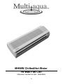
1
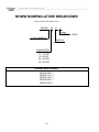
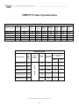
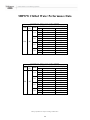
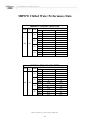
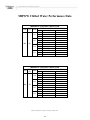
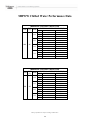
MHWW Chilled/Hot Water
Hi-Wall Fan Coil
2-Pipe Heat / Cool Fan Coil 9,000 - 36,000 BTUH
171
MHWW NOMENCLATURE BREAKDOWN
2-Pipe Heat/Cool Hi-Wall Fan Coil
MHWW-
XX - H
-1
Voltage
1= 208/230/-1-50/60
2-Pipe Heat/Cool
Heat/Cool
Nominal BTUH
09 = 9,000
12 = 12,000
18 = 8,000
24 = 24,000
36 = 36,000
Available Model Numbers
MHWW-09-H-1
MHWW-12-H-1
MHWW-18-H-1
MHWW-24-H-1
MHWW-36-H-1
172
HVAC Guide Specifications
Chilled and Hot Water Hi-Wall Fan Coil
2-Pipe
Nominal Size:
9,000 – 36,000 BTUH
Multiaqua Model Number:
MHWW-09
MHWW-12
MHWW-18
MHWW-24
MHWW-36
Part 1-General
1.01 System Description
Multiaqua Chilled Water Fan Coils are manufactured with high impact molded polymers.
1.02 Quality Assurance
A. Certified in accordance with U.L. Standard 95, latest version (U.S.A.)
B. Manufactured in a facility registered to ISO 9002, Manufacturing Quality Standard.
C. Fully load tested at the factory.
D. Damage resistant packaging.
1.03 Delivery, Storage and Handling
A. Packaged and readied for shipment from the factory.
B. Controls shall be capable of withstanding 150°F storage temperatures in the control compartment.
C. Stored and handled per manufacturer’s recommendations.
Part 2-Product
2.01 Equipment
A. General:
1. Unit shall be a factory assembled and tested chilled and hot water fan coil.
2. Shall be assembled with high quality.
3. Contained with the unit shall be all factory wiring, piping, associated controls and special
accessories required prior to start up.
B. Unit Cabinet:
1. Composed of high impact polymers.
2. Shall be internally insulated to insure quiet operation.
C. Fan Motors:
1. Shall be available in 208/230-1-50/60 vac.
1. Fan motors shall be three speed, direct drive, and PSC type.
2. Totally enclosed.
3. Internal overload protected.
4. Unit shall contain a swing motor to modulate the discharge air.
D. Blower Wheels:
1. Blower wheels are tangential and dynamically balanced.
E. Water Coil:
1. Manufactured with water coils containing 3/8” copper tubing mechanically bonded to aluminum
fins.
2. Coils shall be factory tested to 350 psig
3. Coils are designed to accept an entering water temperature not to exceed 160°F.
F. Drain Pan:
1. All drain pans shall be molded with high impact polymers.
2. The exterior of all drain pans shall be insulated with closed cell to prevent condensation.
3. Pans shall contain a flexible drain tubing that is accessible from the back of the unit.
173
G. Filters:
1. Unit shall contain 65% washable filters.
Part 3-Controls and Safeties
3.01 Controls
A. Fan coils shall be completely factory wired and tested.
B. Controls shall include a circuit board, room sensor, indoor coil thermistor, transformer and wireless
remote.
C. Controls shall be capable of incorporating an optional hard-wired thermostat.
3.02 Safeties:
A. Fan coil shall contain a non reusable fuse on the secondary voltage side of the transformer.
B. Discharge air sensor.
Part 4-Operating Characteristics:
4.01 Electrical Requirements
A. Unit shall incorporate a three prong male primary electrical power cord.
B. Electrical power supply shall be rated to withstand 120°F operating ambient temperatures.
174
MHWW Product Specifications
Physical Data
Model Number
Height
(in)
Length (in)
Depth
(in)
Weight
(lbs)
Cooling
Rows
FPI
Copper
Diameter
(in)
Water
Inlet
(in)
Water
Outlet
(in)
Drain
(in)
MHWW-09-H-1
MHWW-12-H-1
MHWW-18-H-1
MHWW-24-H-1
MHWW-36-H-1
11.70
12.00
14.17
14.17
14.25
34.65
39.00
46.14
46.14
56.50
6.70
7.10
8.10
8.10
8.37
25.70
27.50
44.40
46.20
50.50
2-18
2-18
2-18
3-18
3-18
3/8
3/8
3/8
3/8
3/8
1/2
1/2
1/2
1/2
3/4
1/2
1/2
1/2
1/2
3/4
1/2
1/2
3/4
3/4
3/4
Electrical Data
MHWW-09-H-01
270
MHWW-12-H-01
330
MHWW-18-H-01
480
MHWW-24-H-01
600
MHWW-36-H-01
850
Volts/
Phase/
Hertz
Motor
HP
208/230-1-50/60
Model Number
Hi
Spe
ed
CFM
Full Load
Ampacity
1/60
0.14
1/60
0.17
1/20
0.24
1/20
0.35
1/12
0.42
These specifications are subject to change without notice.
175
Fuse or HACR
Circuit Breaker Per
Circuit
Minimum
Amps
Maximum
Amps
.18
1
.18
1
.30
1
.44
1
.53
1
MHWW Chilled Water Performance Data
MHWW-09 COOLING CAPACITIES
CFM
EWT
(°F)
GPM
1.8
2.0
270
42
2.5
3.0
ENTERING AIR TEMPERATURE (°F)
80° D.B. / 67° W.B.
75° D.B. / 63° W.B.
10.5
7.9
3.6
11.8
8.4
6.0
12.7
8.7
9.0
13.3
9.0
12.6
8.0
7.0
3.6
9.0
7.4
6.0
9.7
7.6
9.0
10.2
7.8
12.6
TC
SC
WPD
TC
SC
WPD
TC
SC
WPD
TC
SC
WPD
MHWW-09 COOLING CAPACITIES
CFM
EWT
(°F)
GPM
1.8
2.0
270
45
2.5
3.0
ENTERING AIR TEMPERATURE (°F)
80° D.B. / 67° W.B.
75° D.B. / 63° W.B.
9.6
7.6
3.6
10.8
8.1
6.0
11.6
8.3
9.0
12.2
8.6
12.6
7.3
6.7
3.6
8.3
7.1
6.0
8.9
7.3
9.0
9.3
7.5
12.6
TC
SC
WPD
TC
SC
WPD
TC
SC
WPD
TC
SC
WPD
These specifications are subject to change without notice.
176
MHWW Chilled Water Performance Data
MHWW-12 COOLING CAPACITIES
CFM
EWT
(°F)
GPM
3.0
4.0
330
42
5.0
6.0
ENTERING AIR TEMPERATURE (°F)
80° D.B. / 67° W.B.
75° D.B. / 63° W.B.
13.7
9.2
11.4
14.3
9.4
15.9
14.8
9.6
17.6
15.1
9.8
21.2
10.4
8.0
11.4
10.9
8.2
15.9
11.3
8.3
17.6
11.5
8.4
21.2
TC
SC
WPD
TC
SC
WPD
TC
SC
WPD
TC
SC
WPD
MHWW-12 COOLING CAPACITIES
CFM
EWT
(°F)
GPM
3.0
4.0
330
45
5.0
6.0
ENTERING AIR TEMPERATURE (°F)
80° D.B. / 67° W.B.
75° D.B. / 63° W.B.
12.5
8.8
11.4
13.1
9
15.9
13.5
9.1
17.6
13.9
9.3
21.2
9.6
7.6
11.4
10.0
7.8
15.9
10.3
7.9
17.6
10.6
8.0
21.2
TC
SC
WPD
TC
SC
WPD
TC
SC
WPD
TC
SC
WPD
These specifications are subject to change without notice.
177
MHWW Chilled Water Performance Data
MHWW-18 COOLING CAPACITIES
CFM
EWT
(°F)
GPM
3.6
4.0
480
42
5.0
6.0
ENTERING AIR TEMPERATURE (°F)
80° D.B. / 67° W.B.
75° D.B. / 63° W.B.
18.6
13.9
3.8
19.9
14.4
5.1
20.8
14.7
6.5
21.5
15.0
8.1
14.2
12.3
3.8
15.2
12.6
5.1
15.9
12.9
6.5
16.4
13.1
8.1
TC
SC
WPD
TC
SC
WPD
TC
SC
WPD
TC
SC
WPD
MHWW-18 COOLING CAPACITIES
CFM
EWT
(°F)
GPM
3.6
4.0
480
45
5.0
6.0
ENTERING AIR TEMPERATURE (°F)
80° D.B. / 67° W.B.
75° D.B. / 63° W.B.
17.1
13.4
3.8
18.2
13.8
5.1
19.1
14.1
6.5
19.7
14.3
8.1
13.1
11.8
3.8
13.9
12.1
5.1
14.6
12.4
6.5
15.0
12.6
8.1
TC
SC
WPD
TC
SC
WPD
TC
SC
WPD
TC
SC
WPD
These specifications are subject to change without notice.
178
MHWW Chilled Water Performance Data
MHWW-24 COOLING CAPACITIES
CFM
EWT
(°F)
GPM
4.8
5.0
600
42
6.0
7.0
ENTERING AIR TEMPERATURE (°F)
80° D.B. / 67° W.B.
75° D.B. / 63° W.B.
TC
SC
WPD
TC
SC
WPD
TC
SC
WPD
TC
SC
23.0
16.0
8.3
23.8
16.3
10.3
24.5
16.6
12.6
25.0
16.8
17.6
14.0
8.3
18.2
14.2
10.3
18.7
14.4
12.6
19.1
14.6
WPD
15.0
15.0
MHWW-24 COOLING CAPACITIES
CFM
EWT
(°F)
GPM
4.8
5.0
600
45
6.0
7.0
ENTERING AIR TEMPERATURE (°F)
80° D.B. / 67° W.B.
75° D.B. / 63° W.B.
21.1
15.3
8.3
21.8
15.6
10.3
22.4
15.8
12.6
23.0
16.0
15.0
16.1
13.4
8.3
16.7
13.6
10.3
17.1
13.8
12.6
17.5
13.9
15.0
TC
SC
WPD
TC
SC
WPD
TC
SC
WPD
TC
SC
WPD
These specifications are subject to change without notice.
179
MHWW Chilled Water Performance Data
MHWW-36 COOLING CAPACITIES
CFM
EWT
(°F)
GPM
7.2
8.0
850
42
9.0
10.0
ENTERING AIR TEMPERATURE (°F)
80° D.B. / 67° W.B.
75° D.B. / 63° W.B.
33.8
24.6
11.8
34.6
24.8
13.7
35.4
25.1
15.8
36.0
25.4
17.9
25.9
21.6
11.8
26.5
21.8
13.7
27.0
22.0
15.8
27.5
22.2
17.9
TC
SC
WPD
TC
SC
WPD
TC
SC
WPD
TC
SC
WPD
MHWW-36 COOLING CAPACITIES
CFM
EWT
(°F)
GPM
7.2
8.0
850
45
9.0
10.0
ENTERING AIR TEMPERATURE (°F)
80° D.B. / 67° W.B.
75° D.B. / 63° W.B.
31.1
23.5
11.8
31.8
23.8
13.7
32.4
24.0
15.8
33.0
24.3
17.9
23.7
20.8
11.8
24.3
21.0
13.7
24.8
21.2
15.8
25.2
21.3
17.9
TC
SC
WPD
TC
SC
WPD
TC
SC
WPD
TC
SC
WPD
These specifications are subject to change without notice.
180
MHWW-09 Hot Water Performance Data
MHWW-09 HEATING CAPACITIES
ENTERING
AIR (°F)
50
CFM
GPM
WPD
270
1.5
2.0
2.5
3.0
3.6
6.0
9.0
12.6
ENTERING WATER TEMPERATURE (°F)
110°
120°
130°
140°
150°
160°
15.6
16.3
16.7
17.0
18.1
19.0
19.5
19.9
20.7
21.7
22.3
22.7
23.3
24.4
25.0
25.5
25.9
27.1
27.8
28.4
28.5
29.8
30.6
31.2
MHWW-09 HEATING CAPACITIES
ENTERING
AIR (°F)
60
CFM
270
GPM
1.5
2.0
2.5
3.0
ENTERING WATER TEMPERATURE (°F)
WPD
3.6
6.0
9.0
12.6
110°
120°
130°
140°
150°
160°
13.0
13.6
13.9
14.2
15.6
16.3
16.7
17.0
18.1
19.0
19.5
19.9
20.7
21.7
22.3
22.7
23.3
24.4
25.0
25.5
25.9
27.1
27.8
28.4
MHWW-09 HEATING CAPACITIES
ENTERING
AIR (°F)
70
CFM
GPM
WPD
270
1.5
2.0
2.5
3.0
3.6
6.0
9.0
12.6
ENTERING WATER TEMPERATURE (°F)
110°
120°
130°
140°
150°
160°
10.4
10.8
11.1
11.3
13.0
13.6
13.9
14.2
15.6
16.3
16.7
17.0
18.1
19.0
19.5
19.9
20.7
21.7
22.3
22.7
23.3
24.4
25.0
25.5
MHWW-09 HEATING CAPACITIES
ENTERING
AIR (°F)
80
CFM
GPM
WPD
270
1.5
2.0
2.5
3.0
3.6
6.0
9.0
12.6
ENTERING WATER TEMPERATURE (°F)
110°
120°
130°
140°
150°
160°
7.8
8.1
8.3
8.5
10.4
10.8
11.1
11.3
13.0
13.6
13.9
14.2
15.6
16.3
16.7
17.0
18.1
19.0
19.5
19.9
20.7
21.7
22.3
22.7
These specifications are subject to change without notice.
181
MHWW-12 Hot Water Performance Data
MHWW-12 HEATING CAPACITIES
ENTERING
AIR (°F)
50
CFM
GPM
WPD
330
3.0
4.0
5.0
6.0
11.4
15.9
17.6
21.2
ENTERING WATER TEMPERATURE (°F)
110°
120°
130°
140°
150°
160°
17.3
17.6
17.8
18.0
20.2
20.5
20.8
21.0
23.0
23.5
23.8
24.0
25.9
26.4
26.7
27.0
28.8
29.3
29.7
29.9
31.7
32.3
32.7
32.9
MHWW-12 HEATING CAPACITIES
ENTERING
AIR (°F)
60
CFM
GPM
WPD
330
3.0
4.0
5.0
6.0
11.4
15.9
17.6
21.2
ENTERING WATER TEMPERATURE (°F)
110°
120°
130°
140°
150°
160°
14.4
14.7
14.9
15.0
17.3
17.6
17.8
18.0
20.2
20.5
20.8
21.0
23.0
23.5
23.8
24.0
25.9
26.4
26.7
27.0
28.8
29.3
29.7
29.9
MHWW-12 HEATING CAPACITIES
ENTERING
AIR (°F)
70
CFM
GPM
WPD
330
3.0
4.0
5.0
6.0
11.4
15.9
17.6
21.2
ENTERING WATER TEMPERATURE (°F)
110°
120°
130°
140°
150°
160°
11.5
11.7
11.9
12.0
14.4
14.7
14.9
15.0
17.3
17.6
17.8
18.0
20.2
20.5
20.8
21.0
23.0
23.5
23.8
24.0
25.9
26.4
26.7
27.0
MHWW-12 HEATING CAPACITIES
ENTERING
AIR (°F)
80
CFM
GPM
WPD
330
3.0
4.0
5.0
6.0
11.4
15.9
17.6
21.2
ENTERING WATER TEMPERATURE (°F)
110°
120°
130°
140°
150°
160°
8.6
8.8
8.9
9.0
11.5
11.7
11.9
12.0
14.4
14.7
14.9
15.0
17.3
17.6
17.8
18.0
20.2
20.5
20.8
21.0
23.0
23.5
23.8
24.0
These specifications are subject to change without notice.
182
MHWW-18 Hot Water Performance Data
MHWW-18 HEATING CAPACITIES
ENTERING
AIR (°F)
50
CFM
GPM
WPD
480
3.0
4.0
5.0
6.0
3.8
5.1
6.5
8.1
ENTERING WATER TEMPERATURE (°F)
110°
120°
130°
140°
150°
160°
27.1
27.8
28.3
28.7
31.7
32.5
33.1
33.5
36.2
37.1
37.8
38.3
40.7
41.7
42.5
43.1
45.2
46.4
47.2
47.9
49.8
51.0
52.0
52.7
MHWW-18 HEATING CAPACITIES
ENTERING
AIR (°F)
60
CFM
GPM
WPD
480
3.0
4.0
5.0
6.0
3.8
5.1
6.5
8.1
ENTERING WATER TEMPERATURE (°F)
110°
120°
130°
140°
150°
160°
22.6
23.2
23.6
23.9
27.1
27.8
28.3
28.7
31.7
32.5
33.1
33.5
36.2
37.1
37.8
38.3
40.7
41.7
42.5
43.1
45.2
46.4
47.2
47.9
MHWW-18 HEATING CAPACITIES
ENTERING
AIR (°F)
70
CFM
GPM
WPD
480
3.0
4.0
5.0
6.0
3.8
5.1
6.5
8.1
ENTERING WATER TEMPERATURE (°F)
110°
120°
130°
140°
150°
160°
18.1
18.6
18.9
19.2
19.5
23.2
23.6
23.9
27.1
27.8
28.3
28.7
31.7
32.5
33.1
33.5
36.2
37.1
37.8
38.3
40.7
41.7
42.5
43.1
MHWW-18 HEATING CAPACITIES
ENTERING
AIR (°F)
80
CFM
GPM
WPD
480
3.0
4.0
5.0
6.0
3.8
5.1
6.5
8.1
ENTERING WATER TEMPERATURE (°F)
110°
120°
130°
140°
150°
160°
13.6
13.9
14.2
14.4
18.1
18.6
18.9
19.2
22.6
23.2
23.6
23.9
27.1
27.8
28.3
28.7
31.7
32.5
33.1
33.5
36.2
37.1
37.8
38.3
These specifications are subject to change without notice.
183
MHWW-24 Hot Water Performance Data
MHWW-24 HEATING CAPACITIES
ENTERING
AIR (°F)
50
CFM
GPM
WPD
600
4.0
5.0
6.0
7.0
8.3
10.3
12.6
15.0
ENTERING WATER TEMPERATURE (°F)
110°
120°
130°
140°
150°
160°
30.3
30.7
31.0
31.3
35.3
35.8
36.2
36.6
40.4
40.9
41.4
41.8
45.4
46.0
46.6
47.0
50.4
51.2
51.7
52.2
55.5
56.3
56.9
57.5
MHWW-24 HEATING CAPACITIES
ENTERING
AIR (°F)
60
CFM
GPM
WPD
600
4.0
5.0
6.0
7.0
8.3
10.3
12.6
15.0
ENTERING WATER TEMPERATURE (°F)
110°
120°
130°
140°
150°
160°
25.2
25.6
25.9
26.1
30.2
30.7
31.0
31.3
35.3
35.8
36.2
36.6
40.4
40.9
41.4
41.8
45.4
46.0
46.6
47.0
50.4
51.2
51.7
52.2
MHWW-24 HEATING CAPACITIES
ENTERING
AIR (°F)
70
CFM
GPM
WPD
600
4.0
5.0
6.0
7.0
8.3
10.3
12.6
15.0
ENTERING WATER TEMPERATURE (°F)
110°
120°
130°
140°
150°
160°
20.2
20.5
20.7
20.9
25.2
25.6
25.9
26.1
30.3
30.7
31.0
31.3
35.3
35.8
36.2
36.6
40.4
40.9
41.4
41.8
45.4
46.0
46.6
47.0
MHWW-24 HEATING CAPACITIES
ENTERING
AIR (°F)
80
CFM
GPM
WPD
600
4.0
5.0
6.0
7.0
8.3
10.3
12.6
15.0
ENTERING WATER TEMPERATURE (°F)
110°
120°
130°
140°
150°
160°
15.1
15.3
15.5
15.7
20.2
20.5
20.7
20.9
25.2
25.6
25.9
26.1
30.3
30.7
31.0
31.3
35.3
35.8
36.2
36.6
40.4
40.9
41.4
41.8
These specifications are subject to change without notice.
184
MHWW-36 Hot Water Performance Data
MHWW-36 HEATING CAPACITIES
ENTERING
AIR (°F)
50
CFM
GPM
WPD
850
7.0
8.0
9.0
10.0
11.8
13.7
15.8
17.9
ENTERING WATER TEMPERATURE (°F)
110°
120°
130°
140°
150°
160°
47.7
48.1
48.5
48.9
55.6
56.2
56.6
57.1
63.6
64.2
64.7
65.2
71.5
72.2
72.8
73.4
79.5
80.2
80.9
81.5
87.4
88.3
89.0
89.7
MHWW-36 HEATING CAPACITIES
ENTERING
AIR (°F)
60
CFM
GPM
WPD
850
7.0
8.0
9.0
10.0
11.8
13.7
15.8
17.9
ENTERING WATER TEMPERATURE (°F)
110°
120°
130°
140°
150°
160°
39.7
40.1
40.5
40.8
47.7
48.1
48.5
48.9
55.6
56.2
56.6
57.1
63.6
64.2
64.7
65.2
71.5
72.2
72.8
73.4
79.5
80.2
80.9
81.5
MHWW-36 HEATING CAPACITIES
ENTERING
AIR (°F)
70
CFM
GPM
WPD
850
7.0
8.0
9.0
10.0
11.8
13.7
15.8
17.9
ENTERING WATER TEMPERATURE (°F)
110°
120°
130°
140°
150°
160°
31.8
32.1
32.4
32.6
39.7
40.1
40.5
40.8
47.7
48.1
48.5
48.9
55.6
56.2
56.6
57.1
63.6
64.2
64.7
65.2
71.5
72.2
72.8
73.4
MHWW-36 HEATING CAPACITIES
ENTERING
AIR (°F)
80
CFM
GPM
WPD
850
7.0
8.0
9.0
10.0
11.8
13.7
15.8
17.9
ENTERING WATER TEMPERATURE (°F)
110°
120°
130°
140°
150°
160°
23.8
24.1
24.3
24.5
31.8
32.1
32.4
32.6
39.7
40.1
40.5
40.8
47.7
48.1
48.5
48.9
55.6
56.2
56.6
57.1
63.6
64.2
64.7
65.2
These specifications are subject to change without notice.
185
MHWW Capacity and Glycol Adjustments
CAPACITY CORRECTION FACTORS
MODEL #
CFM
200
225
250
275
300
325
350
375
400
425
450
500
525
550
575
600
650
675
700
725
750
775
800
825
MHWW-09
TC
SC
0.91 0.88
0.93 0.90
0.96 0.93
MHWW-12
TC
SC
0.92
0.94
0.96
0.98
MHWW-18
TC
SC
MHWW-24
TC
SC
MHWW-36
TC
SC
0.86
0.89
0.92
0.95
0.90
0.92
0.94
0.96
0.86
0.88
0.90
0.93
0.86
0.88
0.91
0.94
0.98
0.84
0.85
0.88
0.91
0.94
0.82
0.85
0.88
0.91
0.93
0.96
0.98
Propylene Glycol & GPM Adjustment Factors
Ambient
Temp
26° F
20° F
8° F
-5° F
-28° F
Propylene
Glycol %
Capacity
Reduction
GPM Adjustment =
100% Capacity
10%
20%
30%
40%
50%
x 0.99
x 0.98
x 0.98
x 0.97
x 0.96
x 1.01
x 1.03
x 1.07
x 1.11
x 1.16
Example:
30% Propylene Glycol Solution.
System capacity x 0.98
GPM x 1.07
These specifications are subject to change without notice
186
0.80
0.82
0.85
0.88
0.90
0.93
0.95
187
INSTALLATION & OPERATING
MANUAL
MHWW Hi-Wall Fan Coils
9,000-36,000 BTUH
-------------------------------------- CAUTION -------------------------------------Care must be taken when handling sheet metal. Sheet metal parts have sharp edges and could
cause injury.
GENERAL
Read the entire contents of this manual
before beginning installation. Multiaqua
assumes no responsibility for equipment
installed contradictory to any code
requirement or installation instructions.
The components of this fan coil have
been inspected at the factory and readied
for shipment. Upon receiving the
shipment a visual inspection of the
packaging must be performed.
If any damage to the packaging is
discovered, an inspection of the
components must be performed and
noted on the delivery documents. If
component damage is found, a damage
claim must be filed by the receiving party
against the delivery party immediately.
horizontal configuration only. See figure 2
for fan coil and mounting plate dimensions.
FAN COIL
MODEL NUMBER
MHWW-09-H-1
MHWW-12-H-1
MHWW-18-H-1
MHWW-24-H-1
MHWW-36-H-1
APPROXIMATED
WEIGHTS (lbs)
25.70
27.50
44.40
46.20
50.50
Figure 1
This product is designed and
manufactured to permit installation in
accordance with national codes. It is the
installer’s responsibility to install the
product in accordance with national
codes and/or prevailing local codes and
regulations.
Care must be taken to ensure the
structural integrity of the supporting
members, clearances and provisions for
servicing, power supply, coil connections
and/or condensate removal. Before the
installation, ensure the structural strength
of the supporting members is sufficient.
See figure 1 for hanging weights of the
fan coils.
This unit is designed to be installed in a
188
INSTALLATION & OPERATING
MANUAL
MHWW Hi-Wall Fan Coils
9,000-36,000 BTUH
FAN COIL AND MOUNTING PLATE DIMENSIONS (in)
Fan Coil Model
Number
A
B
C
D
E
F
G
H
I
MHWW-09
MHWW-12
MHWW-18
MHWW-24
MHWW-36
34.6
39.0
46.0
46.0
57.1
11.7
12.0
14.2
14.2
14.4
7.5
7.5
3.8
3.8
4.0
7.5
7.5
3.8
3.8
4.0
3.5
3.6
6.1
6.1
6.1
2.7
2.7
2.4
2.4
2.8
1.6
1.5
2.4
2.4
1.5
0.8
1.1
1.7
1.7
1.7
1.8
1.7
2.4
2.4
1.5
J
K
Field
Supplied
Hole
L
Field
Supplied
Hole
0.8
1.0
1.8
1.8
1.8
2.8
2.8
2.8
2.8
2.8
2.8
2.8
2.8
2.8
2.8
A
C
D
Mounting Plate
B
H
G
E
F
K
Figure 2
189
I
L
J
INSTALLATION & OPERATING
MANUAL
MHWW Hi-Wall Fan Coils
9,000 – 36,000 BTUH
-------- CAUTION ------Care must be taken when
handling sheet metal. Sheet
metal parts have sharp edges
and could cause injury.
INSTRUCTIONS FOR
INSTALLING THE MOUNTING
PLATE
Figure 3
1. After a suitable place for installation
has been selected, place the mounting
plate horizontally on the wall. Make sure
the alignment is horizontal. Use a plumb
line if available. Mark on the wall where
the mounting holes will be drilled.
Figure 3
2. Drill the holes for the type of
mounting hardware to be used. Check
local building codes for correct mounting
hardware. Secure the mounting plate and
check for stiffness.
Figure 4
3 Drill a diagonal piping access hole (2
.75”) in diameter on both sides of the
mounting bracket. Refer to figure 2 for
field supplied hole locations
Figure 4
4. Check local and national codes for
piping access wall penetrations. See
figure 5 if wall sleeves are required.
Figure 5
Figure 5
190
INSTALLATION & OPERATING
MANUAL
MHWW Hi-Wall Fan Coils
9,000 – 36,000 BTUH
INSTRUCTIONS FOR
INSTALLING FAN COIL
UNIT ONTO MOUNTING
PLATE
1. Route the fan coil piping,
electrical, valve control wires
and/or flexible drain hose through
either of the 2.75” previously
drilled holes in step 3 figure 4.
Ensure that the piping is insulated
per local and national codes.
Improper insulation could result
in voided warranty and/or
building damage.
Figure 6
Figure 6
2. There is a piping channel in the
bottom portion of the back of the
units for crossover piping, drain,
valve control or electrical.
Figure 7
Figure 7
3. Figure 8 depicts (from the
back of the unit) the 24 vac valve
control wires on the left and the
220 vac power cord on the right.
These can be routed to either the
right or left hand side of the fan
coil.
Figure 8
Figure 8
191
INSTALLATION & OPERATING
MANUAL
MHWW Hi-Wall Fan Coils
9,000 – 36,000 BTUH
INSTRUCTIONS FOR
INSTALLING FAN COIL UNIT
ONTO MOUNTING PLATE
4. Ensure that the drain tubing is
installed with at least 1/4” per foot
of downward slope.
Figure 9
5. Secure the fan coil to the mounting
plate by first sliding the fan coil onto
the two notches provided on the
mounting plate.
Figure 9 & 10
6. Push the bottom of the fan coil
towards the wall in order to engage the
locking clips.
Figure 11
7. Connect the liquid solution piping
“flared fittings” and pressure test lines
to make sure there are no leaks.
Figure 10
8. Connect the condensate drain hose.
Make certain that the drain has no traps
or dips in the line that would impede
drainage.
9. Carefully seal any wall penetrations
per local and national codes.
Figure 11
192
INSTALLATION & OPERATING
MANUAL
MHWW Hi-Wall Fan Coils
9,000 – 36,000 BTUH
INSTRUCTIONS FOR
REMOVING THE FAN COIL
COVER AND AIR PURGING
THE LIQUID SOLUTION
COIL.
1. Fold up the filter cover and remove
the three screw covers and screws that
are located below the discharge air
grille. Remove the one screw located
between the two filter racks.
Figure 12
Figure 12
2. Grasp the bottom, sides of the cover
and pull outward.
Figure 13
3. After fan coil and piping has
been pressurized and the fan coil and
piping has no indication of leaks, fill
the system with liquid solution.
Figure 13
4. Energize the control valve to
allow the coil to fill up with liquid
solution.
5. Open the purging valve by using
a standard screw driver and support
fitting with a wrench. Ensure that any
water that discharges from the purging
valve does not come in contact with
the electrical components.
Figure 14
Figure 14
6. When air purging is complete,
close off the purging valve and check
for leaks.
193
INSTALLATION & OPERATING
MANUAL
MHWW Hi-Wall Fan Coils
9,000 – 36,000 BTUH
MHWW CONTROLS OPERATION GUIDE
Wireless Control: Standard Control Package (Page 195)
Optional Wired Control: EG-003 (Page 200)
194
INSTALLATION & OPERATING
MANUAL
MHWW Hi-Wall Fan Coils
9,000 – 36,000 BTUH
MHWW CONTROLS OPERATION GUIDE
Wireless Control:
Name and function of remote controller
Note:
•
•
•
•
•
•
Be sure there are no obstructions between receiver and remote controller.
The remote control signal can be received at the distance of up to about 21 feet.
Do not throw or drop the remote controller.
Do not put any liquid in the remote controller and do not put it in direct sunlight
or any place where it is very hot.
Remove batteries when the remote controller is not in use for extended periods of
time.
The remote controller should be placed 3 or more feet away from any electric
appliance.
LED MODE INDICATOR FOR REMOTE CONTROLLER:
INDICATOR
LIGHTS
RED-GREEN
RED-OFF
RED-RED
RED-OFF
RED-BLINKING
REMOTE
SETTING
COOL
DRY
HEAT
FAN
AUTO
RED-ORANGE
ALERT
FUNCTION
COOLING OPERATION ONLY
HUMIDITY CONTROL, WATER FLOW, NO FAN
HEATING OPERATION ONLY
FAN OPERATION ONLY
AUTO SELECTION BETWEEN HEAT & COOL
DEPENDENT ON ROOM TEMP & SET TEMP
FAN COIL WAITING FOR EWT TO REACH PROPER
TEMPERATURE NECESSARY TO SATISFY SET POINT
195
INSTALLATION & OPERATING
MANUAL
MHWW Hi-Wall Fan Coils
9,000 – 36,000 BTUH
MHWW CONTROLS OPERATION GUIDE
FUNCTION
1. TRANSMISSION SOURCE
- Infra red transmission source
2. POWER
- Press to turn the fan coil on and off or vice versa.
(Red LED left will light to indicate the control is on)
3. MODE
- To select desired operation mode.
It will switch from one to another as shown.
COOL - Cooling operation.
DRY - Humidity control.
HEAT - Heating operation.
FAN - Fan only. No cooling or heating capability.
AUTO - Operation mode will be selected automatically between HEAT and
COOL mode, depending upon the room temperature and SET temperature.
4. FAN
- To select fan speed. It will switch from one to another as shown below.
- When the system temperature sensor is not calling for cool or heat the fan will
run at the speed previously entered in fan mode selection (high, medium or low).
- If auto was the previously entered fan speed in cooling: The fan will run at low
speed until the temperature sensor calls for either heating or cooling at which
point the fan will return to auto speed control
Fan speed sequence
196
INSTALLATION & OPERATING
MANUAL
MHWW Hi-Wall Fan Coils
9,000 – 36,000 BTUH
MHWW CONTROLS OPERATION GUIDE
FUNCTION
5. TEMPERATURE SETTING
- Press “▲” to increase set temperature.
- Press “▼” to decrease set temperature.
- Press “▲” and “▼” Simultaneously to toggle between °C and °F display mode.
- Temperature range: 16°C to 30°C in °C display mode and 60°F to 86°F in °F
display mode.
6. DELAY TIMER SETTING
- The delay timer is capable of delaying both on and off functions. The delay
feature will take affect in all modes with the exception of the sleep mode. Each
time the “▲” and “▼” is pressed it increases or decreases the On or OFF set
point by 1 hour; up to a maximum of 18 hours.
To set the OFF DELAY:
-With the system in operation, enter the system OFF time by pressing the “▲”
button to the desired number of hours ahead that the system will be allowed to
run. When the number of hours entered has elapsed the system will turn off.
To set the ON DELAY:
- Set the on delay by entering the desired mode of operation (fan, heat, cool and
the appropriate temperature. This will be the settings the system will follow
when operation resumes. After setting the mode and any applicable
temperature with the control, turn the remote off. Now enter the number of
hours to elapse before operation resumes by pressing the “▲” button on the
remote to the desired number. When the time (in hours) entered has elapsed,
the system will resume operation according to the pre-set mode and
temperature.
197
INSTALLATION & OPERATING
MANUAL
MHWW Hi-Wall Fan Coils
9,000 – 36,000 BTUH
MHWW CONTROLS OPERATION GUIDE
7.
8.
CANCEL
- To cancel any setting on the delay timer.
LOUVER
- Two different functions are available:
1. To set the louver stop position. There are 4 angles available. The sequence is as
follows.
2. To set the louver swing (continuous motion). The sequence is as follows.
9. SLEEP
- This function when selected will allow the user to determine a “sleep” period. In
cooling the selected temperature will rise to 1° above set point in 1/2 hour,
rising to 2° in 1 hour, rising again to 4° after 2 hours of the SLEEP CYCLE.
SLEEP FUNCTION DISPLAY
10. DRY
- This function operates to control humidity within a conditioned space. It
measures the difference between set point and the actual room temperature.
An algorithm determines how far above set point the actual room temperature is
to set point temperature and selects periods of water valve operation and low fan
operation. The greater the difference between room temperature and set point
temperature prompts greater run time with less temperature. With less
temperature differences, periods of fan and valve operation are called for in
varying increments as determined by the difference. In this mode (low speed) fan
operation will start 30 seconds after valve has opened and stops 30 seconds after
valve has closed.
198
INSTALLATION & OPERATING
MANUAL
MHWW Hi-Wall Fan Coils
9,000 – 36,000 BTUH
MHWW CONTROLS OPERATION GUIDE
11. AUTO
- This function will automatically control the system switching between heating and
cooling operation. If the preset auto mode is cooling, a switch to heating
operation will begin only if the actual room temperature is 7° below selected
control set point. If the present auto mode is heating, a switch to cooling operation
will begin only when the room temperature is 3° above selected control set point.
12.
TRANSMISSION INDICATOR
- Blinks twice to indicate that transmission has taken place between remote and
receiver.
- Beeps indicate fan coil acknowledging receipt of transmission.
TRANSMISSION INDICATOR
13. HOW TO INSERT BATTERIES
1. Remove the battery cover from the back of the remote.
2. Insert the (2) AAA batteries. Ensure that the polarity of the batteries are as shown
inside of the battery compartment.
3. Re-attach the battery compartment cover.
199
INSTALLATION & OPERATING
MANUAL
MHWW Hi-Wall Fan Coils
9,000 – 36,000 BTUH
MHWW CONTROLS OPERATION GUIDE
Optional Wired Control: EG-003
LED MODE INDICATOR FOR REMOTE CONTROLLER:
INDICATOR LIGHTS
RED-GREEN
RED-RED
RED-BLINKING
RED-OFF
SETTING
COOL
HEAT
AUTO
FAN
FUNCTION
COOLING OPERATION ONLY
HEATING OPERATION ONLY
AUTO SELECTION BETWEEN HEAT & COOL
FAN OPERATION ONLY
1. POWER
- Press to turn the fan coil on and off or vice versa.
2. MODE
- To select desired operation mode.
It will switch from one to another as shown.
COOL - Cooling operation.
HEAT - Heating operation.
FAN - Fan only. No cooling or heating capability.
AUTO - Operation mode will be selected automatically between HEAT and
COOL mode depending upon the room temperature and SET temperature.
3. FAN
- To select fan speed. It will switch from one to another as shown below.
- When the system temperature sensor is not calling for cool or heat the fan will run at
the speed previously entered in fan mode selection (high, medium or low).
- If auto was the previously entered fan speed in cooling: The fan will run at low speed
until the temperature sensor calls for either heating or cooling at this point the fan
will return to auto speed control
Fan Speed Sequence
200
INSTALLATION & OPERATING
MANUAL
MHWW Hi-Wall Fan Coils
9,000 – 36,000 BTUH
MHWW CONTROLS OPERATION GUIDE
FUNCTION
4. TEMPERATURE SETTING
- Press “▲” to increase set temperature.
- Press “▼” to decrease set temperature.
- Press “▲” and “▼” Simultaneously to toggle between °C and °F display mode.
- Temperature range: 16° C to 30°C in °C display mode and 60°F to 86°F in °F
display mode.
5.
6.
CANCEL
- To cancel any setting on the delay timer.
LOUVER
- Two different functions are available:
1. To set the louver stop position. There are 4 angles available. The sequence is as follows.
2. To set the louver swing (continuous motion). The sequence is as follows.
7. AUTO
- This function will automatically control the system switching between heating and
cooling operation. If the present auto mode is cooling, a switch to heating
operation will begin only if the actual room temperature is 7° below selected
control set point. If the present auto mode is heating, a switch to cooling operation
will begin only when the room temperature is 3° above selected control set point.
201
MHWW-09-H-1 & MHWW-12-H-1 Wiring Diagram
208/230/-1-50/60
ROOM SENSOR
MULTIAQUA
INDOOR COIL
THERMISTOR
ID
RM
RESET SWITCH
FUSE
CON 1
LIVE
2
NOTE 3
CON 2
WIRELESS
REMOTE
NC TO COIL
COOLING
IR
LIVE
1
4WV
SM
OPERATE
DISPLAY
BOARD
OF\WCV
L (SEC)
NOTE 7
COOL
HEAT
NOTE 5
CON 3
N
SWING MOTOR
YL
R
D
B
R
BL
RD
YL
TITLE
NC TO COIL
HEATING/
COOLING
NOTE 6
1
2
3
4
5
L2
6
L2
BK
BK
NOTE 1
MHWW-09-H-1 & MHWW-12-H-1 4-PIPE OR 2-PIPE WIRING DIAGRAM
POWER CORD
208/230-1 vac
1. POWER CORD IS EQUIPPED WITH A 3-PRONG MALE PLUG
4-PIPE WIRING
2-PIPE WIRING
05/04/11
PC
NOTES:
LEGEND:
AUTHOR
REVISION
WH
7
L1
FACTORY WIRING
DATE
B
K
NOTE 4
BK
NC TO COIL
HEATING
G
R
INDOOR
FAN
MOTOR
NOTE 2
OPTIONAL WALL
MOUNTED
HARD-WIRED
CONTROLLER
EG-003
Y
W
L
H
2-PIPE WIRING
JUMPER
2. 208/230 -24vac TRANSFORMER
3. WIRELESS REMOTE INCLUDES A WALL MOUNTING BRACKET
4. JUMPER MUST BE FIELD INSTALLED FOR 2-PIPE HEAT/COOL
OPERATION
5. 4-PIPE WIRING AND VALVE CONFGURATION
6. 2-PIPE WIRING AND VALVE CONFGURATION
GROUND
0607300015 REV 1
202
7. OPTIONAL WALL MOUNTED THERMOSTAT. EG-003.
MHWW-18-H-1 Wiring Diagram
208/230/-1-50/60
ROOM SENSOR
MULTIAQUA
INDOOR COIL
THERMISTOR
ID
RM
RESET SWITCH
FUSE
CON 1
LIVE
2
NOTE 3
CON 2
WIRELESS
REMOTE
IR
4WV
NC TO COIL
COOLING
L (SEC)
SM
OPERATE
DISPLAY
BOARD
OF\WCV
NOTE 7
COOL
HEAT
NOTE 5
LIVE
1
CON 3
N
SWING MOTOR
W
H
B
L
Y
L
G
R
YL
BL
RD
YL
NC TO COIL
HEATING
TITLE
NOTE 6
1
2
3
4
5
L2
6
L2
BK
BK
NOTE 1
PC
POWER CORD
208/230-1 vac
NOTES:
MHWW-18-H-1 4-PIPE OR 2-PIPE WIRING DIAGRAM
LEGEND:
1. POWER CORD IS EQUIPPED WITH A 3-PRONG MALE PLUG
FACTORY WIRING
4-PIPE WIRING
2-PIPE WIRING
REVISION
BR
7
L1
AUTHOR
DATE
WH
NOTE 4
BK
NC TO COIL
HEATING/
COOLING
CAP
OPTIONAL WALL
MOUNTED
HARD-WIRED
CONTROLLER
EG-003
RD
INDOOR
FAN
MOTOR
NOTE 2
05/04/11
2-PIPE WIRING
JUMPER
2. 208/230 -24vac TRANSFORMER
3. WIRELESS REMOTE INCLUDES A WALL MOUNTING BRACKET
4. JUMPER MUST BE FIELD INSTALLED FOR 2-PIPE HEAT/COOL
OPERATION
5. 4-PIPE WIRING AND VALVE CONFGURATION
6. 2-PIPE WIRING AND VALVE CONFGURATION
0907300042 REV 1
GROUND
203
7. OPTIONAL WALL MOUNTED THERMOSTAT. EG-003.
MHWW-24-H-1 Wiring Diagram
208/230/-1-50/60
ROOM SENSOR
MULTIAQUA
INDOOR COIL
THERMISTOR
ID
RM
RESET SWITCH
FUSE
CON 1
LIVE
2
NOTE 3
CON 2
WIRELESS
REMOTE
IR
4WV
NC TO COIL
COOLING
L (SEC)
SM
OPERATE
DISPLAY
BOARD
OF\WCV
NOTE 7
COOL
HEAT
NOTE 5
LIVE
1
CON 3
N
SWING MOTOR
W
H
B
L
Y
L
B
K
YL
BL
RD
YL
NC TO COIL
HEATING
TITLE
NOTE 6
1
2
3
4
5
L2
6
L2
BK
NOTE 1
PC
POWER CORD
208/230-1 vac
NOTES:
MHWW-24-H-1 4-PIPE OR 2-PIPE WIRING DIAGRAM
LEGEND:
1. POWER CORD IS EQUIPPED WITH A 3-PRONG MALE PLUG
FACTORY WIRING
4-PIPE WIRING
2-PIPE WIRING
REVISION
BK
7
L1
AUTHOR
DATE
WH
BR
NOTE 4
BK
NC TO COIL
HEATING/
COOLING
CAP
OPTIONAL WALL
MOUNTED
HARD-WIRED
CONTROLLER
EG-003
RD
INDOOR
FAN
MOTOR
NOTE 2
05/04/11
2-PIPE WIRING
JUMPER
2. 208/230 -24vac TRANSFORMER
3. WIRELESS REMOTE INCLUDES A WALL MOUNTING BRACKET
4. JUMPER MUST BE FIELD INSTALLED FOR 2-PIPE HEAT/COOL
OPERATION
5. 4-PIPE WIRING AND VALVE CONFGURATION
6. 2-PIPE WIRING AND VALVE CONFGURATION
0907300043 REV 1
GROUND
204
7. OPTIONAL WALL MOUNTED THERMOSTAT. EG-003.
MHWW-36-H-1 Wiring Diagram
208/230/-1-50/60
ROOM SENSOR
MULTIAQUA
INDOOR COIL
THERMISTOR
ID
RM
RESET SWITCH
FUSE
CON 1
LIVE
2
NOTE 3
CON 2
WIRELESS
REMOTE
IR
4WV
NC TO COIL
COOLING
L (SEC)
SM
OPERATE
DISPLAY
BOARD
OF\WCV
NOTE 7
COOL
HEAT
NOTE 5
LIVE
1
CON 3
N
SWING MOTOR
W
H
Y
L
B
R
B
K
YL
BL
RD
YL
NC TO COIL
HEATING
TITLE
NOTE 6
1
2
3
4
5
L2
6
L2
BK
7
L1
NOTE 1
PC
POWER CORD
208/230-1 vac
NOTES:
MHWW-36-H-1 4-PIPE OR 2-PIPE WIRING DIAGRAM
LEGEND:
1. POWER CORD IS EQUIPPED WITH A 3-PRONG MALE PLUG
FACTORY WIRING
4-PIPE WIRING
2-PIPE WIRING
REVISION
BK
NOTE 4
AUTHOR
DATE
WH
RD (50 Hz)
BK
NC TO COIL
HEATING/
COOLING
OR(60 Hz)
CAP
OPTIONAL WALL
MOUNTED
HARD-WIRED
CONTROLLER
EG-003
GY
INDOOR
FAN
MOTOR
NOTE 2
05/04/11
2-PIPE WIRING
JUMPER
2. 208/230 -24vac TRANSFORMER
3. WIRELESS REMOTE INCLUDES A WALL MOUNTING BRACKET
4. JUMPER MUST BE FIELD INSTALLED FOR 2-PIPE HEAT/COOL
OPERATION
5. 4-PIPE WIRING AND VALVE CONFGURATION
6. 2-PIPE WIRING AND VALVE CONFGURATION
GROUND
0907300044 REV 1
205
7. OPTIONAL WALL MOUNTED THERMOSTAT. EG-003.
MHWW CERTIFIED DRAWING
206