1
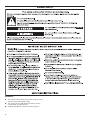
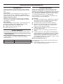
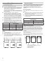
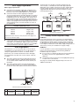
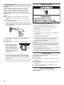
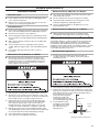
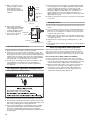
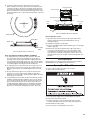
INSTALLATION INSTRUCTIONS
MFS18, MFS25, MFS35, MFS55
COMMERCIAL WASHER
TABLE OF CONTENTS
WASHER SAFETY ................................................................... 2
INSTALLATION REQUIREMENTS.......................................... 3
Tools and Parts....................................................................... 3
Optional Equipment ............................................................... 3
Location Requirements ......................................................... 3
...Electrical Requirements......................................................... 6
Water Supply Requirements .................................................. 7
Drain Requirements ............................................................... 7
Laundry Product Dispenser Pumps....................................... 7
INSTALLATION INSTRUCTIONS ............................................ 8
Inspection and Storage ......................................................... 8
Mechanical Installation .......................................................... 8
Remove Shipping Brackets ................................................... 8
Electrical Connection ............................................................ 9
W
ater Supply Connection ..................................................... 9
Drain Connection ................................................................... 9
Laundry Product Supply Pump Connection ......................... 9
C
omplete Installation ........................................................... 10
B
reak-In Period ................................................................... 10
Controls Troubleshooting .................................................... 10
WASHER MAINTENANCE ....................................................... 11
Maintenance Schedule........................................................... 11
Vibration Switch Adjustment and Function Test.................... 11
Belt Inspection, Adjustment, and Replacement.....................12
Door Seal Adjustment and Replacement...............................12
Fuse Replacement.................................................................13
Opening Door Without Power ...............................................13
DIMENSIONS AND TECHNICAL SPECIFICATIONS.. .............14
Dimensions.............................................................................14
Component Locations............................................................15
Technical Specifications.........................................................16
Torque Specifications.............................................................16
W10214572C
www.maytagcommerciallaundry.com
1
WASHER SAFETY
IMPORTANT:
■■
This washer must be directly wired to the electrical system
and may not be attached with a plug.
■■
The circuit must be a dedicated circuit and may not be
combined with any lighting circuit.
■■
Adequate grounding is essential to washer operation.
2
INSTALLATION REQUIREMENTS
Tools and Parts
Gather the required tools and parts before starting installation.
Read and follow the instructions provided with any tools listed
here.
Tools needed:
These washers must be installed by professional installers. The
installer should have a full compliment of standard SAE and
metric hand tools as well as other specialized tools as required.
Additional materials required:
Additional materials required vary with the type of installation.
The customer is responsible for supplying additional hardware
and adapters as necessary.
Parts supplied:
Remove parts bag from washer drum. Check that all parts were
included. The number of parts supplied varies with model.
■■ Molded rubber drain hose and band clamp
■■ Rubber washers for the hoses (4 or 6)
■■ Water supply hoses (2 or 3)
Optional Equipment
The following optional equipment is available for these washers.
Steam Heater Kit
Steam heating kits is available for Model MFS55 only.
To add a steam kit to your washer, order the kit specified
in the table below:
Model
Steam Kit Number
MFS55PNA
W10308483
Location Requirements
Washers should be installed on a level concrete floor on the
ground level of a building; they can also be installed on an
elevated concrete pad up to 12" (300 mm) above the surrounding
floor. Consult a structural engineer to approve other locations.
The models MFS18 and MFS25 washers can also be mounted
on an elevated metal base up to 12" (300 mm) high.
Proper installation is your responsibility. The installation must
meet all governing codes and ordinances.
You will need:
■■ The washer should be located in a building and not directly
exposed to the weather. The temperature of the building
should be 40–95°F (5–35°C) during operation.
■■ A hot water heater set between 120–160°F (49–80°C).
■■ Valved hot and cold water supply (3/4" male NPT fitting)
within 4 ft. (1.2 m) of the washer with a water pressure
between 43 and 73 PSI (0.3–0.5 MPa).
■■ A dedicated, GFCI-equipped circuit for each washer (see
“Electrical Requirements”).
■■ Adequate sanitary sewer drainage located behind each
washer.
■■ A solid concrete floor or slab capable of withstanding the
weight and vibration produced by the washer. The maximum
slope of the floor is 1" (25 mm) under the washer. A rough
concrete surface is preferable to a smooth or covered
surface when the washer is not secured, to keep the washer
from walking during extraction cycles.
Minimum Installation Clearances:
The location must be large enough to allow the washer door to
open completely.
■■ There should be adequate access behind and above the
washer for maintenance and service.
3
Dim.
27.6" (701 mm)
Model
MFS18
MFS25
MFS35
MFS55
A
25.99"
(660 mm)
25.99"
(660 mm)
32.67"
(830 mm)
35.46"
(901 mm)
B
28.15"
(715 mm)
32.48"
(825 mm)
38.39"
(975 mm)
36.40"
(925 mm)
C
42.50"
(1080 mm)
44.90"
(1140 mm)
51.00"
(1300 mm)
56.30"
(1430 mm)
D
44.50"
(1130 mm)
48.40"
(1230 mm)
58.70"
(1490 mm)
63.60"
(1620 mm)
Installation on an elevated base
P
P
P
Front View
NOTES:
MFS18
MFS25
MFS35
MFS55
0.6" (15 mm)
0.6" (15 mm)
0.8" (20 mm)
0.8" (20 mm)
* Door may not open completely with this minimum clearance
■■
■■
Models MFS35 and MFS55 are mountable on either a metal
base or an elevated cement slab; however, they must be
adequately secured.
Minimum clearances should be maintained when installing
washers in an elevated position.
Fixed Installation on Concrete Floor or Elevated
Concrete Pad (all models)
23.6" (600 mm)
All washer models can be installed on an elevated cement slab.
The base must be able to withstand both the load and vibration
of the washer. The washer must be secured with anchor bolts
(See “Installation Instructions”). Install the 4 anchors before final
installation of the washer.
12"
(300 mm)
max. elevation
4" (100 mm)
Side View
Freestanding Installation on Elevated Concrete Pad
(Models MFS18 and MFS25 only)
Product Dimensions
General product dimensions are shown below. See Technical
Specifications for dimensions not shown here.
Models MFS18 and MFS25 can be installed on an elevated
concrete pad without bolts by installing a metal channel at the
front of the concrete pad to secure the front washer mounting
feet. Specifications of the metal channel are shown in the figure
below. The channel must be firmly secured with anchors or
self-tapping cement screws.
2.38"
(60 mm)
0.63"
(15 mm)
C
0.160"
(4 mm) 12"
min. (300 mm)
max.
D B
A
4
Elevated Metal Base for Secured Installation
The elevated metal base for a secured installation may be
fabricated from a metal U-channel as shown in the illustration
below. The maximum allowable height of the base is 12"
(300 mm). The base must be able to withstand both the load
and vibration of the washer. The base must be adequately
secured with anchor bolts or cement anchors.
Dim.
Model
MFS18
MFS25
MFS35
MFS55
X4
3.81"
(97 mm)
3.42"
(87 mm)
1.97"
(50 mm)
1.06"
(27 mm)
X5
(min.)
4.53"
(115 mm)
4.53"
(115 mm)
5.32"
(135 mm)
4.76"
(121 mm)
X6
5.12"
(130 mm)
5.12"
(130 mm)
3.15"
(80 mm)
1.55"
(39.5 mm)
X7
2.76"
(70 mm)
2.76"
(70 mm)
1.77"
(45 mm)
6.69"
(170 mm)
Elevated Metal Base for Freestanding Installation
(Models MFS18 and MFS25 only)
A
Minimum material thickness 0.160" (4 mm)
U-Channel
0.160"
(4 mm)
min.
The elevated metal base for a freestanding installation
must be constructed in the same way as the base for a secured
installation. An additional U channel must be welded or bolted
to the top of the front rail to secure the front washer mounting
feet (see illustration below).
12"
(300 mm)
max.
A
Anchor Bolt Placement
B
Minimum material thickness 0.160" (4 mm)
X5
X4
U-Channel
X7
2.38"
(60 mm)
Outline of cabinet
Outline of frame
B
0.63"
(15 mm)
Outline of riser
C
Inside of riser
X6 X2
X1
X3
12"
(300 mm)
max.
0.19"
(5 mm)
B
D
A
Dim.
X3
Model
MFS18
MFS25
MFS35
MFS55
A
25.99"
(660 mm)
25.99"
(660 mm)
32.67"
(830 mm)
35.46"
(901 mm)
B
28.15"
(715 mm)
32.48"
(825 mm)
38.39"
(975 mm)
36.40"
(925 mm)
C
17.91"
(455 mm)
22.24"
(565 mm)
32.09"
(815 mm)
33.30"
(846 mm)
D
22.05"
(560 mm)
22.05"
(560 mm)
28.15"
(715 mm)
31.50"
(800 mm)
X1
1.14"
(29 mm)
1.14"
(29 mm)
1.18"
(30 mm)
1.77"
(45 mm)
X2
3.46"
(88 mm)
3.46"
(88 mm)
1.97"
(50 mm)
1.06"
(27 mm)
X3
1.97"
(50 mm)
1.97"
(50 mm)
2.26"
(57.5 mm)
1.98"
(50.5 mm)
5
Electrical Requirements
Connection to Washer
It Is Your Responsibility
■■
■■
■■
■■
■■
To contact a qualified electrical installer.
To be sure that the electrical connection is adequate and in
conformance with the National Electrical Code, ANSI/NFPA
70-latest edition, or Canadian Electrical Code CSA C22.1,
and all local codes and ordinances.
A copy of the above code standards can be obtained from:
National Fire Protection Association, One Batterymarch Park,
Quincy, MA 02269.
To supply the required 3 or 4 wire, single phase,
208-240 volt, 60 Hz., AC electrical supply on a separate
circuit. Circuit capacity is dependent on washer size and
connection type and is shown in the tables below. A timedelay fuse or circuit breaker is recommended. Installation
of a GFCI is also recommended. Connect to an individual
branch circuit. Do not fuse the neutral or grounding circuit.
A separate ground wire is recommended if codes permit.
It is recommended that a qualified electrician determine the
ground path is adequate.
Coin-operated washers do not have an emergency stop
switch. A remote emergency stop device must be installed.
The switch must be easily accessable to all users and meet
the requirements of ISO13850-category 0.
Phase (Voltage)
These washers were designed for direct wiring into the power
supply. The washer must be electrically grounded in accordance
with local codes or, in the absence of local codes, with the
National Electrical Code, ANSI/NFPA 70, latest edition, or
Canadian Electrical Code, CSA C22.1, and all local codes and
ordinances.
Direct wire installation:
Power supply cable must match power supply (4-wire or 3-wire)
and be:
■■
■■
Flexible armored cable or nonmetallic sheathed copper cable
(with ground wire), in a flexible metallic conduit. All current
carrying wires must be insulated.
Copper wire of appropriate gauge for amperage requirement
(see table below). Stranded wire is recommended. Do not
use aluminum wire.
Minimum Recommended
Conductor Gauges
Fuse or Breaker
Minimum AWG*
15A
14
20A
12
*Copper stranded wire recommended.
Model
1 (208–240V)
3 (208–240V)
MFS18
15A
15A
Equipment Potential Bonding:
MFS25
15A
15A
MFS35
20A
20A
MFS55
Not Applicable
20A
In addition to the individual washing machine ground wires
used in conjunction with the power supply wiring, all washers
must be connected with one another using separate insulated
conductors #3 in the illustration below. The first and last washers
will subsequently be connected to a protective conductor that
completes the loop of the protective ground circuit, #1 in the
illustration.
The external protective connection points that serve for this
purpose (see illustration).
The wire size of the protective conductor #1 must be at least as
large as the insulated conductors #3 being used to interconnect
the washing machines.
NOTES:
■■ Connecting these washers to IT power supplies requires
special considerations.
■■ When installing multiple single phase washers into an
existing 3-phase power supply, alternating the phase used
as the hot leg is recommended to evenly distribute power on
the system. See illustration.
3
3
4
3
2
5
PE
L1 L2 L3
PE
L1 L2 L3
PE
L1 L2 L3
3
1
1.
2.
3.
4.
5.
6
Protective grounding structure
External protective conductor connection point
Protective conductor
Grounding identification
Washer (rear view)
Water Supply Requirements
Water supply requirements:
■■
■■
Valved hot and cold water supply with a water pressure
between 14.5 and 116 PSI (100–800 kPa). Water pressure
between 43 and 73 PSI (300–500 kPa) is recommended.
A hot water heater or boiler supplying an adequate
amount of water between 120–160°F (49–80°C). The water
temperature within the washer is controlled to a maximum
temperature that is set in the program. The amount of hot
water required to wash a load of laundry is dependent on
many factors, including the hot and cold water temperature
and the wash program selected. Average amounts of hot
water required to wash one load of laundry are shown in
the table below.
he drain pipe must be able to handle wastewater from all
T
of the washers, so the diameter of the drain pipe required is
dependent on the number of washers in the line. Sanitary drains
must be vented and meet all local and municipal codes. The
suggested drain diameter for one to three washers is shown
in the illustration below.
3"
(76 mm)
4"
(102 mm)
5"
(127 mm)
Flow
Hot water requirement per load
Washer Model
MFS18
MFS25
MFS35
MFS55
Hot water per load*
4.0 gal. (15 L)
4.5 gal. (16 L)
8.0 gal. (31 L)
10.5 gal. (40 L)
*Approximate values. Assumes 140°F (60°C) hot water supply and
70°F (21°C) cold water supply.
■■
It is also necessary to connect all available water inlets to a
water supply. If three inlets are present, then two should be
cold water—one a hard water supply, and the other a soft
water supply. If a hard and soft connection is not available,
connect to whatever cold water supply is available.
Drain Requirements
The washer has a 3" (75 mm) water drain on its rear side. A
molded drain hose that extends up to 43" (1.09 m)and hose
clamp are supplied with the washer. To maintain washer
performance, do not reduce the diameter of the drain pipe.
The washer drain may drain into a waste channel or directly
to a drain.
■■
■■
The waste channel cannot be located under the washer.
There should be at least 4" (100 mm) between the back
of the washer and the middle of the waste channel (see
illustration).
The waste channel must be lower than the drain pipe.
There should be at least a 3/4" (20 mm) air gap between
the bottom of the drain and the water level in the channel.
Drain Diameter Requirements
Laundry Product Dispenser Pumps
PN Models
Physical and electrical control connections for external liquid
laundry product pumps are included in all PN models. If laundry
product dispenser pumps will be used, the pumps should have
an adequate flow rate to deliver the required amount of product
to the dispenser within 30 seconds. Relay supply voltage was set
at the factory. Check your material list for supply voltage.
PD Models
It is also possible to connect external liquid laundry product
pumps to PD model washers, but the following additional
installation steps are required:
■■ It is necessary to complete the physical connection between
the tubing connector not supplied with PDs, and the
dispenser.
■■ The electrical control connection to the liquid product pumps
is made on the control board.
See page 9, “Laundry Product Supply Pump Connection” for
additional information.
X
4"
(102 mm)
3/4"
(19 mm)
Minimum Waste Channel Measurements
X
MFS18
MFS25
MFS35
MFS55
2.9"
(73 mm)
2.9"
(73 mm)
2.2"
(55 mm)
5.5"
(140 mm)
7
INSTALLATION INSTRUCTIONS
3. L
evel the washer first side to side, then front to back using
metal shims. Be sure that the washer does not tip from side
to side. Tighten the anchor bolts. Thread on and tighten
the locking nuts.
Inspection and Storage
Freestanding installation on level or elevated base
(Models MFS18 and MFS25 only):
1. S
tand the washer upright. Slide or lift the washer into place.
N
OTE: If mounting on a metal base or elevated slab, be sure
the front rubber feet are inside the metal channel.
2. With washer in final position, place a level on top of the
washer, first side to side; then front to back. If the washer
is not level, adjust the legs of the washer up or down with
a 1/2" (13 mm) wrench until the washer is level. Be sure
that the washer does not rock. Tighten the locking nuts.
1. Inspect carton for damage. Inspect
washer if carton shows signs of
damage. Do not remove washer
from pallet.
1. Concrete floor
2. Metal channel
3. Rubber foot
4. Washer frame
2. V
erify model number and serial
number on the data plate with
your order.
3. S
tore inside in a temperature
Data Plate
controlled environment 33–130°F
(1–55°C). Do not expose washer to the weather.
1
Metal Channel
Fixed installation on concrete floor or elevated concrete pad
(all models):
1. Elevate washer and remove the rubber feet from the bottom
of the washer. Move the washer into its final position. Thread
bolts into anchors to hold in place. Do not tighten bolts at this
time.
2. L
evel the washer first side to side, then front to back; use
metal shims to level. Be sure that the washer does not tip in
any direction before tightening. Tighten the 4 anchor bolts.
Concrete floor
Anchor bolt
Flat Washer
Washer frame
M8 bolt
4
2
6. M8 nut
7. M8 jam nut
8. E
levated
metal base
1
Concrete Floor or Pad
8
Remove Shipping Brackets
1. Remove rear panel and front service panel, if not already removed.
2. R
emove shipping brackets. Retain brackets and bolts if
needed to secure the washer for transport in the future.
3. Replace both panels.
7
6
4
5
3
3
2
Mechanical Installation
1. M
ove the washer near the point of installation with a lift truck
or fork lift. Remove packing material.
2. Remove rear panel and front service panel, if not already
removed. Remove the bolts attaching the washer to the pallet.
IMPORTANT: This washer is very heavy. Consider equipment
and manpower required to move this washer prior to
installation and be sure that all necessary preparations are
made. See page 16, “Technical Specifications”.
1.
2.
3.
4.
5.
4
2
3
Shipping Brackets (Models MFS18, MFS25, and MFS35)
3
1
Elevated Metal Base
Fixed installation on elevated metal base
(Models MFS18 and MFS25 only):
1. Be sure that base is secured to the floor.
2. S
lide or lift the washer into its final position. Thread bolts
from base to flat washer to hold in place. Do not tighten bolts
at this time.
Front bracket
Shipping Brackets (Model MFS55)
8
Rear brackets
(2)
Electrical Connection
Water Supply Connection
Connect the water supply to the washer using the flexible inlet
hoses provided. Do not use a rigid connection for the water
supply.
NOTE: The water connection to the washer
requires a 3⁄4" British Standard Pipe Thread
fitting. The ground end is a U.S. thread.Threading
an NPT fitting or the NPT end of the inlet hose
will damage the threads of the fill valve.
NPT fitting
1. F
lush water lines to remove debris. Install the
rubber washers in both fitting ends of each inlet
hose. Install the non-grooved fitting nut of the inlet
hoses to the hot and cold inlet valves. Tighten
fittings.
British standard
2. Attach grooved end of the inlet
pipe thread
hoses to the washer. Tighten fittings.
fitting
3. Turn on water and check for leaks
in the system.
1. Turn off power at fuse box or breaker box.
2. O
pen top of washer with key. Prop the top open with
the support.
3. R
emove approximately 6" (150 mm) of shielding from cable
end to expose insulated wires. Be sure that there is sufficient
wire to create a drip loop or wire sag, as shown.
Drain Connection
1. C
ut the pre-formed drain hose so it fits properly on the drain
or in the drain channel.
2. Attach drain hose to washer with clamp provided. If fitted directly to a drain pipe, use a clamp on the drain pipe as well.
Laundry Product Supply Pump Connection
Up to 8 laundry product supply pumps may be connected to the
washer. Tubing and relay connections are provided in the back
of the washer.
NOTE: Route hoses and wiring so they will not be pinched,
damaged, or rubbed during use.
A drip loop or wire sag keeps
condensation from running
into washer
Electrical Relay Connection
The electrical connections are relay connections only and do
not provide adequate power for the pumps. The laundry product
supply pump(s) must be powered by a separate electrical source.
4. S
trip wire insulation an adequate
length to make connections. Install
eyelets on ground wires with a
crimping tool.
5. R
emove locking nut from strain relief provided with washer.
Thread wire through strain relief and thread wire through
hole in back of the washer until strain relief penetrates hole.
Route strain relief nut around wires and tighten nut onto
strain relief body.
PN Models
1. Turn off power at circuit breaker or fuse box.
2. Remove panel screw and remove cover. Connect relay leads
to numbers 1 through 8. Connect common/ground to lead 10.
3. Replace cover.
6. C
onnect two or three current conducting wires into the
connector and tighten the screw connectors; single phase
and three-phase connections are shown in the illustrations.
Attach ground to the frame ground bolt as shown in the
illustrations and tighten the locking nut.
L1 L2 L3
3-phase connection
Ground
Ground
L1 L2
Single-phase connection
PD Models
1. Turn off power at circuit breaker or fuse box.
2. Open top cover. Route control wires through washer and
to relay connector on control panel. Connect leads.
N
OTE: Support control wires with wire ties to keep them
away from moving parts.
3. Replace cover.
9
Complete Installation
Tubing Connectors
All models
There are 6 tubing connectors in back of the washer. One
connector is larger in diameter than the others. The larger
diameter connector should be used for the pump requiring
chemical mixing with water prior to entering the washer. If
additional chemicals are needed, contact the manufacturer.
Tubing connectors are sealed at the factory and must be drilled
out before use.
NOTES:
■■ Only drill out connectors that will be used. Any unused
open connectors must be sealed to avoid reflux during
the fill cycle.
■■ Holes must be drilled. Attempting to open holes with a punch
may damage the washer.
1. D
rill out connectors that will be used. Use a drill bit slightly
smaller than the interior diameter of the hole. Small tubes are
11/32" and larger tube is 13/32". Remove all debris from the
hole. See illustration.
2. Attach flexible hoses rated for commercial laundry chemicals
to the connectors. (Secure hoses with hose clamps.)
PD models only
These additional steps are necessary to connect tubing
connectors:
3. O
pen top cover. Locate
connectors that were drilled.
Attach tightly fitting flexible
hoses rated for commercial
laundry chemicals onto those
connectors on the inside of the
washer, long enough to reach
the dispenser box connectors.
Secure each hose with
a hose clamp.
4.
Dispenser connectors –
Rear view
B
e sure that dispenser connectors fit the hoses. Drill out
connectors on the dispenser box with a drill bit slightly
smaller than the interior diameter of the hole. Small tubes
are 11/32" and larger tube is 13/32". Remove all debris
from the hole.
5. A
ttach flexible hoses rated for commercial laundry chemicals
to the connectors. Secure the hoses with a hose clamp.
1. Turn off power at fuse box or breaker box.
2. Be sure that the shipping brackets are removed.
3. Open door and be sure that the washer drum is empty.
4. Verify that washer is level and does not rock from
side-to-side.
5. Check electrical connection and ground.
6. Turn on water.
7.Adjust vibration switch. See “Vibration Switch Adjustment”
in Maintenance.
8. Check drain connection and clearance.
9. Turn power on at circuit breaker.
10.
Turn the washer on. Begin a wash cycle. Watch the drum
during the extraction cycle. The drum should rotate
clockwise as observed from the front of the washer.
11. Make sure all panels are installed.
IMPORTANT: If the drum rotates counter-clockwise in extract
mode, turn off the power supply at the circuit breaker and reverse
the polarity of any 2 of the supply wires from the frequency
inverter to the motor, or on the motor itself. This should only be
performed by qualified personnel.
11. Perform vibration switch function test (see page 11 “Vibration
Switch Adjustment and Function Test”).
12. Begin wash cycle again. Activate the emergency stop switch.
All electrical power to the washer should be deactivated.
Break-In Period
The following checks and adjustments should be performed
during the break-in period as follows:
24 operation hours
■■ Check belt tightness. See page 12, “Belt Inspection and
Adjustment”.
80 operation hours
■■ Check belt tightness. See page 12, “Belt Inspection and
Adjustment”.
■■ Check mounting bolt tightness. Retighten if necessary
(secured installation only).
Controls Troubleshooting
For programming and controls troubleshooting, refer to the
Programming Guide.
10
WASHER MAINTENANCE
Maintenance Schedule
After Each Load
■■
■■
Remove debris from the wash drum including paper clips,
coins, and other hard items.
When not in use, leave the washer door open to allow the
washer to air out and prolong gasket life.
Maintenance Every 1000 Hours or 6 Months
■■
■■
■■
■■
Daily Maintenance
■■
■■
■■
■■
■■
■■
Remove water, detergent, and other stains off of the washer
with a soft cloth dampened with a mild detergent solution.
Dry with a soft cloth. Do not use abrasives.
Remove detergent residue and other contamination off the
door seal with a soft cloth dampened with a mild detergent
solution.
Wipe clean the bottom of the door glass of any debris that
may settle there.
Remove residue from the soap hoppers with a plastic
scraper. Wipe the hoppers with a soft cloth dampened with
water.
Check water and steam inlets for leaks. Correct as
necessary.
Maintenance Every 500 Hours or 3 Months
■■
1.
2.
3.
4.
5.
6.
Observe the washer from the back for one wash cycle.
Be sure that water does not leak out of the drain during
the wash part of the cycle and that it drains freely at the
beginning of extraction. Clean the drain valve if either of
these symptoms are observed.
Turn off power to washer at the circuit breaker or fuse box.
U
nlock top cover of washer, remove dispenser screws, and
open top (see Top View on page 15 for location of dispenser).
Remove bolts/screws securing rear panel of washer.
Inspect all hoses and connections inside the washer for
leaks and correct as necessary. Remove dust and debris
from inside the washer with a shop vacuum and soft
bristled attachment. Pay particular attention to the motor
cooling fins, inverter cooling fins, cooling fans, and vents.
W
ipe up any stains with a soft cloth dampened with water
or a mild detergent solution. Be sure that control components
are not exposed to dust and moisture during cleaning.
Check that all bolts are properly torqued.
Turn on power at circuit breaker or fuse box.
Turn off hot and cold water to the washer at the the valves.
Clean water valve screens.
Be sure ventilator fans are functioning (some models).
Inspect belt and check belt tension. See page 12, “Belt
Inspection, Adjustment, and Replacement”.
Check mounting bolt tightness. Retighten if necessary
(fixed installation only).
Maintenance Every 2000 Hours or 12 Months
■■
Adjust and perform functional test on vibration switch
(see Vibration Switch Adjustment and Function Testing).
Vibration Switch Adjustment and Function Test
The Vibration Switch is a critical component of the washer that
avoids washer damage during extraction of an unbalanced
load. Vibration Switch adjustment must be performed during
installation and checked annually. The Vibration Switch is located
toward the front of the washer on top of the drum and can be
accessed by opening the top cover.
Vibration Switch Adjustment
1. If washer was just installed, run washer through one
complete extraction cycle without a load so the drum is
at its balance point.
2. Turn off power to washer at the circuit breaker or fuse box.
3. Unlock top cover of washer, remove dispenser screws, and
open top (see Top View on page 15 for location of dispenser).
Prop up the front of the cover on all but the MFS18 where
the top panel also has 2 bolts
at the rear of the top panel
and the top needs to be
Static arm
removed by lifting up on the
rear and sliding the top forward.
4. L
ocate vibration switch
1 3/16"
assembly. Check floating
(30 mm)
Sensor
arm adjustment. Loosen
spring
the static arm bolts to
adjust distance.
Switch
Floating arm
Floating arm distance adjustment
11
5. M
ake sure that the sensor
spring is roughly centered
in the floating arm slot
horizontally and about 1/3
of the way from the bottom
vertically.
Sensor
spring
Floating arm
Adjusting
bolt
Centering Sensor Spring –
Front View
6. A
djust switch gap with a
feeler gauge (see illustration).
Loosen adjustment screws
to adjust. Retighten screws
when adjusted properly.
7. Turn on power at circuit Adjustment
screws
breaker or fuse box.
Switch
0.008" (0.2 mm)
Switch Gap Adjustment
Vibration Switch Function Test
1. Begin extraction cycle with no load in the washer.
2. Unlock
top cover of washer, remove dispenser screws, and
open top (see Top View on page 15 for location of dispenser).
Prop up the front of the cover on all but the MFS18 where the
top panel also has 2 bolts at the rear of the top panel and the
top needs to be removed by lifting up on the rear and sliding
the top forward.. Locate vibration sensor assembly.
3. Push down on the spring sensor with a screwdriver or other
long-handled tool. The extraction cycle should stop. If
extraction does not stop, the sensor requires adjustment
or is defective.
Belt Inspection, Adjustment and Replacement
Belt Inspection and Adjustment
1. Turn off power to washer at the circuit breaker or fuse box.
2. R
emove bolts securing the rear panel of washer. Remove rear
panel. Inspect belt for signs of wear and damage. Replace the
belt if worn or damaged. See “Belt Replacement”.
3. B
e sure that the belt pulleys are aligned by laying a straight
edge along the drum pulley. The motor pulley should be in
line with the straight edge. If the pulleys are not aligned,
loosen the motor mounting bolts and adjust. Re-tighten motor
mounting bolts.
12
4. C
hecking the belt tension requires a straight edge and a belt
tension gauge. Place the straight edge from the drum pulley
to the motor pulley. Belt tension is correct when a 13 lb.
(60 N) force applied to the midpoint of the belt between the
two pulleys deflects the belt 9/16 to 3/4" (15–20 mm). To
adjust the belt, first loosen the locking nut and loosen or
tighten the belt as necessary. Re-tighten the locking nut when
adjusted and re-check.
5. Replace rear panel of washer. Turn on power at circuit breaker
or fuse box.
Belt Replacement
1. Remove bolts securing the rear panel of washer. Remove rear panel.
2. Loosen locking nut and loosen belts. On Models MFS18 and
MFS25, it is necessary to press on the motor to remove the
belts. Do not use a prybar or screwdriver to remove the belts
except to hold up the motor.
3. Replace with new belts of the same type. When a belt needs to be replaced, always replace the complete set of belts when more than 1 are used.
4. Adjust belts. See “Belt Inspection and Adjustment” on this page.
5. Reinstall rear panel of washer. Turn power on at circuit breaker
or fuse box.
Door Seal Adjustment and Replacement
Water leaks around the door seal may occur as the gaskets
age. In most cases, this can be resolved through cleaning the
door glass and seal or a door adjustment. In severe cases, seal
replacement is necessary. These procedures are discussed here.
Door Seal Adjustment (Models MFS18 and MFS25)
1. Remove the front cover around the latch. Set cover aside.
2. Increase (decrease) door seal pressure on the hinge and latch
sides by removing (inserting) spacer shims between the hinge
or latch and door frame. Tighten bolts and locking nuts.
3. Make sure that the door pin is in the center of the door lock opening. Loosen the hinge screws slightly to reposition
the door, if necessary. Open the door and re-tighten the screws/bolts when the pin is centered. Add a screw lock compound to maintain proper adjustment.
4. C
heck the gasket pressure. Open door and close door
latch on the door. Close the door until the closed door latch
contacts the roller on the door lock. Slowly release pressure
on the door and allow the door to spring back. Measure the
distance between the roller and latch without pressure on the
latch. Gasket pressure is correct when the distance is 0.2–0.4"
(5–10 mm).
Longitudinal beam
Lock cover bolt
Cross beam
Door lock cover
Door
lock
Door frame
Door glass
bolt
Door frame
bolt
Door frame
bolt
Door hinge
bolt
Square
washers
Door Seal (Models MFS35 and MFS55)
Door frame
Door glass
Door seal
Door hinge
bolts
Door Seal (Models MFS18 and MFS25)
Door Seal (Models MFR18 and MFR25)
Door Seal Adjustment (Models MFS35 and MFS55)
1. T
o adjust pressure on the hinge side, open the door and
loosen the door frame bolts clamping the door frame to
the hinge. Take out the square washers. Tighten the bolts.
Loosen the door hinge bolts. Insert one, two or three square
washers between the longitudinal beam and the cross beam
as needed. Tighten door hinge bolts when adjusted.
2. T
o adjust pressure on the latch side, remove the lock cover
bolts and lock cover. Remove the door lock bolts. Remove
distance lock washers as needed. Replace door lock and
latch.
3. Be sure that the door pin is in the center of the door lock
opening. Loosen the hinge screws slightly to reposition
the door, if necessary. Open the door and re-tighten the bolts
when the pin is centered.
4. C
heck gasket pressure. Open the door and leave door latch
handle in unlatched position while the door is open. Slowly
close the door until the door latch contacts the roller on the
door lock. Release pressure on the door slowly; the door
should spring back slightly. Measure the distance between
the roller and latch without pressure on the latch. Gasket
pressure is correct when the distance is 0–0.2" (0–5 mm).
Door Seal Replacement
1. Open the door. Remove the door glass with rubber from
the door frame by pushing it toward the drum. Do not
damage the glass.
2. Separate the gasket from the glass.
3. Place a new rubber gasket with the wider groove on the glass
with the edge up.
4. Moisten the seal groove gasket with soapy water. Place
a smooth cord in the groove so it goes around the entire
circumference. Fit the assembly to the door frame. Hold
one end of the cord firmly on the door. Pull the other cord
end toward the center of the glass and work the gasket onto
the door.
Fuse Replacement
All washers have 2-1A in-line fuses at the back of the washer.
Model MFS55 has an additional 0.5 A in-line fuse.
Opening Door Without Power
In case of a power failure, the door may not open.
To open the door without power:
1. Turn off power supply at the circuit breaker or fuse box.
2. Remove the front service panel.
3. Find the emergency cord on the left side of the washer.
Pull the cord firmly until you hear a faint click. Open door.
4. Reinstall front service panel.
5. Turn on power at circuit breaker or fuse box.
13
DIMENSIONS AND TECHNICAL SPECIFICATIONS
Dimensions
R
R
C
C
G
D
P
A
G
F
Front View (Models MFS18 and MFS25)
J
D
P
H
Front View (Models MFS35 and MFS55)
S
E
A
V
T
B
K
Top View
I
U
L
Back View
W
M
N
Q
14
Q
MFS18
MFS25
MFS35
MFS55
A
25.99" (660 mm)
25.99" (660 mm)
32.67" (830 mm)
35.46" (901 mm)
B
28.15" (715 mm)
32.48" (825 mm)
38.39" (975 mm)
36.40" (925 mm)
C
42.50" (1080 mm)
44.90" (1140 mm)
51.00" (1295 mm)
56.50" (1435 mm)
D
22.10" (560 mm)
22.10" (560 mm)
28.20" (715 mm)
31.50" (799 mm)
E
17.91" (455 mm)
22.24" (565 mm)
32.09" (815 mm)
33.30" (846 mm)
F
0.80" (20 mm)
0.80" (20 mm)
—
—
G
15.50" (420 mm)
18.90" (480 mm)
16.90" (430 mm)
23.00" (585 mm)
H
10.40" (263 mm)
10.40" (263 mm)
11.80" (300 mm)
10.40" (263 mm)
I
35.80" (910 mm)
38.20" (970 mm)
44.70" (1135 mm)
48.20" (1225 mm)
J
4.10" (103 mm)
4.10" (103 mm)
4.70" (120 mm)
4.10" (103 mm)
K
38.60" (980 mm)
40.90" (1040 mm)
47.00" (1195 mm)
51.80" (1315 mm)
L
1.70" (44 mm)
1.70" (44 mm)
1.70" (44 mm)
17.70" (450 mm)
M
32.90" (835 mm)
35.20" (895 mm)
40.00" (1015 mm)
50.60" (1285 mm)
N
3.10" (78 mm)
3.10" (78 mm)
2.20" (55 mm)
5.50" (140 mm)
O
14.80" (375 mm)
14.80" (375 mm)
16.30" (415 mm)
28.30" (720 mm)
P
0.60" (15 mm)
0.60" (15 mm)
0.80" (20 mm)
0.80" (20 mm)
Q
17.50" (445 mm)
17.50" (445 mm)
20.90" (530 mm)
20.90" (530 mm)
R
27.60" (700 mm)
27.60" (700 mm)
27.60" (700 mm)
27.60" (700 mm)
S
23.60" (600 mm)
23.60" (600 mm)
23.60" (600 mm)
23.60" (600 mm)
T
2.70" (68 mm)
2.70" (68 mm)
7.87" (200 mm)
6.61" (168 mm)
U
33.50" (850 mm)
33.50" (850 mm)
41.70" (1060 mm)
42.90" (1092 mm)
V
—
13.30" (339 mm)
18.50" (470 mm)
17.50" (445 mm)
W
—
34.40" (874 mm)
41.40" (1052 mm)
44.90" (1140 mm)
Component Locations
1
1
Front View (Models MFS35 and MFS55)
Front View (Models MFS18 and MFS25)
2 4 3
5
6 7 9
8
13
14
15
15
12
Top View
Back View
11
1. Control panel
2. Connection liquid soap
3. Data plate
4. Air relieve
5. Water supply
6. Air vent holes, Frequency inverter
7. Fuses
8. Main switch
10
9. Electrical supply connection
10. Drain
11. Adjustable feet
12. Steam connection
13. Soap dispenser
14. Liquid soap relay board box
15. Earth connection
15
Technical Specifications
MFS18
MFS25
MFS35
MFS55
Washer
dimensions
(width x depth x height)
25.99 x 28.15 x 42.50"
(660 x 715 x 1080 mm)
25.99 x 32.48 x 44.90" 32.67 x 38.39 x 51.00" 35.46 x 36.40 x 56.50"
(660 x 825 x 1140 mm) (830 x 975 x 1295 mm) (901 x 925 x 1435 mm)
Net weight
519 lb. (235 kg.)
607 lb. (275 kg.)
Package dimensions
29.50 x 33.50 x 49.30"
(750 x 850 x 1250 mm)
29.50 x 37.40 x 51.20" 36.60 x 44.90 x 59.50" 38.40 x 47.30 x 63.80"
(750 x 950 x 1300 mm) (930 x 1140 x 1510 mm) (975 x 1200 x 1620 mm)
Gross weight
552 lb. (250 kg.)
662 lb. (300 kg.)
Dimensions and Weights
Transportation volume
m3)
27.9 cu.ft. (0.8
32.5 cu.ft. (0.9
1026 lb. (465 kg.)
1092 lb. (495 kg.)
m3)
56.5 cu.ft. (1.6
m3)
1433 lb. (650 kg.)
1522 lb. (690 kg.)
67.1 cu.ft. (1.9 m3)
Electrical Requirements
Supply Voltage (50/60 Hz)
208–240V 1-phase*
208–240V 3-phase
Fuse/Breaker Type
Slow (curve D)
GFCI**
Class B
Water Supply Requirements
Allowable water pressure
14.5–116 psi (100–800 KPa)
Recommended pressure
43–73 psi (300–500 KPa)
Water inlet
BSP 3/4"
Maximum water temperature
194°F (90°C)
Drain Requirements
Drain diameter
3" (76 mm)
Flow rate
56 GPM (3.5 l/s)
Environmental Requirements
Operating temperature
41 to 95 °F (5 to 35°C)
Relative humidity
30 to 90 % without condensation
Elevation above sea level
Up to 3280 ft. (1,000 m)
Storage temperature
32 to 131°F (0 to 55°C)
Floor Requirements
Maximum static load
560 lb. (2492 N)
675 lb. (3002 N)
1225 lb. (5450 N)
1770 lb. (7860 N)
Maximum dynamic load
164 lb. (730 N)
248 lb ( 1100 N)
275 lb. (1220 N)
366 lb. (1626 N)
Dynamic frequency
16 Hz
16 Hz
16 Hz
15 Hz
<70 dB(A)
<70 dB(A)
<70 dB(A)
<70 dB(A)
Noise
Noise output
G 1/2"
Steam Connection
Low pressure
14.5–44 PSI
(100–303 KPa)
High pressure
44–116 PSI
(303–800 KPa)
* 2 phases of a 3-phase power supply may be used. See “Electrical Requirements”.
** Consult an electrician to ensure proper GFCI connection.
Torque Specifications
Recommended Torque Values for Steel Bolts
W10214572C
16
Bolt Size
Torque
M6
8 ft. lbs. (10 Nm)
M8
20 ft. lbs. (25 Nm)
M10
35 ft. lbs. (45 Nm)
M12
60 ft. lbs. (80 Nm)
M16
150 ft. lbs. (200 Nm)
© 2012 Maytag. All rights reserved.
08/2012
Printed in the Czech Republic