1
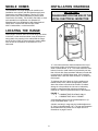
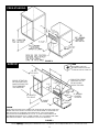
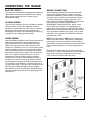
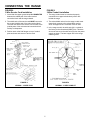
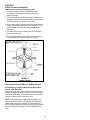
INSTALLER: LEAVE THESE INSTRUCTIONS WITH THE APPLIANCE
INSTALLATION MANUAL
Electric 30-inch Free-standing,
Slide-in & Drop-in Ranges
PLEASE KEEP THIS MANUAL FOR FUTURE REFERENCE
THE MANUAL IS INTENDED TO ASSIST IN THE INITIAL INSTALLATION AND ADJUSTMENTS OF THE RANGE.
SPECIAL WARNING
Only qualified personnel should
install or service this range.
Read “Safety Instructions” in the
Use & Care book before using
range.
Improper installation, adjustment,
alteration, service, maintenance or
use of range can result in serious
injury or property damage.
CLEARANCE DIMENSIONS
For complete information in regard to installation
of free-standing, drop-in and slide-in ranges,
see figures 1 through 4 on pages 2, 3 and 4. For
SAFETY CONSIDERATIONS do not install a
range in any combustible cabinetry which is not
in accord with the installation clearances shown
in figure 1.
CAUTION: Some cabinets and building
materials are not designed to withstand the
heat produced by the normal safe operation
of a listed appliance. Discoloration or
damage, such as delamination, may occur.
Your range may not be equipped with some of the features referred
to in this manual.
8101P329-60
(05-99-01)
MOBILE HOMES
INSTALLATION DRAWINGS
The installation of a range designed for mobile home
installation must conform with the Manufactured Home
Construction and Safety Standard, Title 24 CFR, Part
3280 (formerly the Federal Standard for Mobile Home
Construction and Safety, Title 24 HUD, Part 280) or, when
such standard is not applicable, the Standard for
Manufactured Home Installations 1982 (Manufactured
Home Sites, Communities and Set-Ups), ANSI
A225.1-latest edition, or with local codes.
IMPORTANT
PLEASE KEEP FOR THE USE OF THE
LOCAL ELECTRICAL INSPECTOR.
4
LOCATING THE RANGE
1
Place range in a well lit area. Do not set range over holes
in the floor or other locations where it may be subject to
strong drafts. Any opening in the wall behind the range
and in the floor under the range should be sealed. Make
sure the flow of combustion or ventilation air is not
obstructed.
2
3
“A”
FIGURE 1
“A” = 30 inches minimum clearance between the top of
the cooking surface and the bottom of an unprotected
wood or metal cabinet, or “A” = 24 inches minimum when
bottom of wood or metal cabinet is protected by not less
than 1/4-inch thick flame-retardant millboard covered with
not less than No. 28 MSG sheet steel, 0.015-inch thick
stainless steel, 0.024-inch thick aluminum, or 0.020-inch
thick copper.
To eliminate the risk of burns or fire by reaching over
heated surface units, cabinet storage space located
above the surface units should be avoided. If cabinet
storage is to be provided, the risk can be reduced by
installing a range hood that projects horizontally a
minimum of 5 inches beyond the bottom of the cabinets.
FIGURE 1
1, 2, 3 - COMBUSTIBLE BUILDING WALLS.
4 - COMBUSTIBLE WALL CABINET.
A free-standing range may be installed adjacent to (0²
from) combustible walls 1, 2 & 3.
A slide-in and drop-in range may be installed adjacent to
(0² from) combustible walls 2 & 3. The rear wall clearance
will be determined by cabinet cut-out depth shown in
illustrations on pages 3 and 4.
-2-
FREE-STANDING
FIGURE 2
NOTE:
ON CABINET TOPS WITH
FORMED FRONT EDGE, SHAVE
RAISED SECTION TO CLEAR TOP.
SLIDE-IN
*23 1/4²
CUT DEPTH
BEFORE ATTEMPTING
INSTALLATION, ADJUST
RANGE LEVELING LEGS
TO ACCOMMODATE
THIS DIMENSION.
30²
5 1/2²
5 1/2²
PROVIDE FOR 120/208,
120/240 VOLT OUTLET
PER APPLICABLE
CORD IN THIS AREA.
10²
23 5/8² MIN.
FLAT
25² MINIMUM
AREA
COUNTER
TOP DEPTH
36² COUNTER
TOP HEIGHT
30² CABINET
OPENING
24² CABINET
DEPTH
CAUTION:
SOME WHITE EUROPEAN STYLE CABINETS ARE EQUIPPED WITH DELICATE WHITE VINYL
DRAWER AND DOOR FRONTS. THE VINYL MAY NOT BE DESIGNED TO WITHSTAND THE
HEAT PRODUCED BY THE NORMAL SAFE OPERATION OF A SELF-CLEAN RANGE.
DISCOLORATION OR DELAMINATION MAY OCCUR. TO AVOID POSSIBLE DAMAGE, WE
RECOMMEND INCREASING THE 30² CABINET OPENING TO 31 1/4² MINIMUM AND USING
HEAT SHIELD KIT-CABKIT V. THE COUNTERTOP CUT-OUT MUST REMAIN 30².
FIGURE 3
* When replacing an existing unit, a maximum of 23 1/2² is acceptable. If the cut depth exceeds 23 1/2², use filler kit (K70 Fill).
-3-
DROP-IN
NOTE:
ON CABINET TOPS WITH
FORMED FRONT EDGE, SHAVE
RAISED SECTION TO CLEAR TOP.
*23 1/4² CUT DEPTH
PROVIDE FOR 120/208, 120/240
VOLT JUNCTION BOX FOR RANGE
CONDUIT BELOW UNIT.
24²
CABINET
DEPTH
1 1/4²
36² COUNTER
TOP HEIGHT
23 5/8² MIN.
FLAT AREA
25² MINIMUM
COUNTER
TOP DEPTH
27 1/2²
FROM TOP OF
COUNTER
30²
CABINET
OPENING
NOTE: BEFORE
ATTEMPTING INSTALLATION,
ADJUST RANGE LEVELING
LEGS TO ACCOMMODATE
THIS DIMENSION.
RECOMMEND THE USE OF
3 1/2² WIDE SLATS ON EACH SIDE.
24²
CABINET
DEPTH
FIGURE 4
* When replacing an existing unit, a maximum of 23 1/2² is acceptable. If the cut depth exceeds 23 1/2², use filler kit (K70 Fill).
-4-
ANTI-TIP DEVICE INSTALLATION INSTRUCTIONS
WARNING: A risk of range tip-over exists if the appliance
is not installed in accordance with the provided installation
instructions. The proper use of this device minimizes the
risk of TIP-OVER. In using this device the consumer must
still observe the safety precautions as stated in the USE
and CARE MANUAL and avoid using the oven door
and/or lower drawer as a step stool.
to the wall with the two screws provided as shown
in figure 6. Proceed to STEP 3.
B. Cement or Concrete Construction:
1. Suitable screws for concrete construction can be
obtained at the hardware store. Drill the required
size hole for the hardware obtained into the
concrete at the center of the holes identified in
figure 5 as “HOLES FOR FLOOR”. Secure the
ANTI-TIP bracket to the floor. Proceed to STEP 3.
Installation instructions are provided for wood and cement
in either floor or wall. Any other type of construction may
require special installation techniques as deemed
necessary to provide adequate fastening of the ANTI-TIP
bracket to the floor or wall. The bracket may be installed
to engage the left or right rear leveling leg.
STEP 3 - Range Installation
A. Free-standing and slide-in ranges may be installed by
one person. The drop-in requires two persons due to
adjusting leveling legs and making electrical
connection while range is suspended in cut-out.
B. Align the range to its designated location and slide it
back into position. Note: A minimum clearance of 1/4²
is required between the range and the leveling foot
that will engage the ANTI-TIP bracket, see figure 6.
CAUTION: Damage to the range may occur if range
is moved or lifted by grasping the main top or
backguard. (If equipped).
STEP 1 - Locating The Bracket (See Figure 5)
A. Determine where either the right or left “EDGE” of the
range will be located and mark the floor or wall.
B. Place the BRACKET 15/16² from the marked “EDGE”
toward center of opening and against the back wall,
as shown in figure 5.
C. Use the bracket as a template and mark the required
holes, as shown in figure 5 for the type of construction
you will be using.
C. All slide-in and drop-in ranges are equipped with a
non lift-up top. All free-standing ranges with a glass
top are non lift-up. Coil tops are lift-up except for
some Canadian models that are non lift-up.
D. For SAFETY CONSIDERATIONS as well as optimum
performance adjust the range so that it is level. This
may be checked by placing a spirit level or a large
pan of water on the cooktop or the oven rack. If an
adjustment is required on free-standing, pull the range
forward, tip the range and rotate the leveling feet as
required. Slide-in and drop-in ranges require total
removal from cabinet before an adjustment can be
made.
E. To check the range for proper installation of the
anti-tip bracket: Use a flashlight and look underneath
the bottom of the range to see that one of the rear
leveling legs is engaged in the bracket slot.
F. Proceed with the remainder of the installation
instructions provided with the range.
D. Free-standing and slide-in ranges may be secured to
either floor or wall. Drop-in range may only be
secured to slat in cabinet.
STEP 2 - Anti-Tip Bracket Installation
A. Wood Construction:
1. Floor: Locate the center of the two holes identified
in figure 5 as “HOLES FOR FLOOR”. Drill a 1/8²
pilot hole in the center of each hole (a nail or awl
may be used if a drill is not available). Secure the
ANTI-TIP bracket to the floor with the two screws
provided. Proceed to Step 3.
2. Wall: Locate the center of the two holes identified
in figure 5 as “HOLES FOR WALL”. Drill an
angled 1/8² pilot hole in the center of each hole as
shown in figure 6. (A nail or awl may be used if a
drill is not available). Secure the ANTI-TIP bracket
FREE-STANDING: FASTEN BRACKET TO WALL OR
FLOOR.
FIGURE 5
FIGURE 6
-5-
CONNECTING THE RANGE
ELECTRIC SUPPLY
RANGE CONNECTIONS
The range must be installed in accordance with Local and
National Electric Code (NEC) ANSI/NFPA No. 70-latest
edition. See rating plate on front of range for total
connected KW rating.
Some models are shipped direct from the factory with
service cords (pigtails) attached. There are no range
connections necessary on these models. Just plug into
the range outlet. On models not provided with a service
cord and models having a conduit, connection to the
power supply is necessary. REMEMBER - mobile homes
and some LOCAL CODES DO NOT PERMIT
GROUNDING THROUGH NEUTRAL. Hence, 4-wire
service MUST be provided for such installations. All
others permit 3-wire service. Use COPPER WIRE ONLY.
Make connections as explained below and with reference
to the appropriate illustration (see figures 7 thru 9). After
installation, insure tightness of all electrical connections
and replace all covers.
OUTSIDE WIRING
Your local utility company will tell you whether the present
electric service to your home is adequate. It may be
necessary to increase the size of the wiring to the house
and service switch to take care of the electrical load
demanded by the range. The kilowatt rating for the range
is specified on the name plate on the range.
HOUSE WIRING
NOTE: Cord replacement - ONLY a power supply cord
rated at 240 volts minimum, 40 amperes or 50 amperes
power supply cord that is marked for use with nominal 1
3/8² (34.93 mm) diameter connection opening, with closed
loop terminals and marked for use with ranges shall be
used.
Most local Building Regulations and Codes require that all
electrical wiring be done by licensed electricians. All
wiring should conform to Local and National Electrical
Codes. This range requires a single phase three wire
120/240 or a 120/208 volt, 60 Hz, AC circuit. Wiring codes
require a separate circuit be run from the main entrance
panel to the range and that it be equipped with separate
disconnect switch and fuses, either in the main entrance
panel or in a separate switch and fuse box. In some
communities, a solid or flexible continuous armored
conduit must be used from main entrance panel to the
terminal box on the rear of the range. Others will permit
the termination of the range circuit at a polarized three or
four wire plug-in outlet placed at a convenient point near
the back of the range. The range is then connected to this
outlet through an approved range connector (pigtail)
fastened securely to the terminal block with proper strain
relief at the range and a three or four pronged plug at the
opposite end.
Remove terminal block access cover from range back.
(See figure 7). Figure 7 shows the back of a free-standing
range. slide-in and drop-in ranges have a flat access
cover on the left side of the main wire cover.
FIGURE 7
-6-
CONNECTING THE RANGE
FIGURE 8
3-Wire Service Cord Installation
FIGURE 9
3-Wire Conduit Installation
1. Insure that the copper ground strap IS CONNECTED
between the middle post of the main terminal
connection block and the range chassis.
1. The range conduit must be routed and properly
connected to an approved electrical junction box
behind the range.
2. The middle wire of the service cord MUST connect to
the neutral (middle) post of the main terminal block.
The other two wires of the service cord connect to the
outside posts of the main terminal connection block.
Polarity is unimportant.
2. The red and black wires from the range conduit must
respectively connect to the red and black service
wires. An approved wire connector must be used.
3. In the range conduit, the white wire (N) is twisted at
the factory to the uninsulated (BARE) wire. This bare
wire must connect to the white wire (N) from the power
supply as shown. The bare copper wire is the range
chassis ground.
3. Position strain relief with flanges on top of conduit
plate as shown and secure to service cord.
FIGURE 8
NORMAL - 3 WIRE PLUG
FIGURE 9
NORMAL - 3 WIRE CONDUIT
-7-
CONNECTING THE RANGE
FIGURE 10
4-Wire Service Cord Installation
(Mobile Homes Or As Required By Codes)
1. The copper ground strap connected between the
neutral (middle) post of the main terminal block and the
chassis MUST be cut off as shown in figure 10. Use the
green ground screw to attach the green (chassis
ground) from the 4 conductor cord. Keep the green
ground screw. Only a 4 conductor cord should be used.
2. The green wire from the service cord must connect to
the range chassis using the green ground screw.
3. The white wire of the service cord must connect to the
neutral (middle) post of the main terminal block. The
other two wires of the service cord connect to the red
and black posts of the main terminal block,
respectively.
4. Position the strain relief with flanges on top of conduit
plate as shown and secure to service cord.
FIGURE 10
4-WIRE PLUG
-8-
FIGURE 11
4-Wire Conduit Installation
(Mobile Homes Or As Required By Codes)
1. The range conduit must be routed and properly
connected to an approved electrical junction box
behind the range.
2. The red and black wires from the range conduit must
respectively connect to the red and black service wires.
An approved wire connector must be used.
3. In the range conduit, the white wire (N) is twisted at the
factory to the uninsulated ground wire (BARE). For a 4
wire installation, the white and bare wire MUST be
separated.
4. The white wire from the conduit must be connected to
the white service wire.
5. The uninsulated (bare) wire from the conduit must be
connected either to a green or bare service wire.
FIGURE 11
4-WIRE CONDUIT
Conversion From 3-Wire To 4-Wire Service
(Free-Standing or Slide-in Models Only With 3-Wire
Service Cord Attached).
Disconnect range from power. Remove the access cover
on back of range and remove the 3-wire service cord from
the main terminal block. Follow instructions as outlined in
figure 8 to connect the 4-wire service cord.
NOTE: Cord replacement - ONLY a power supply cord
rated at 240 volts minimum, 40 amperes or 50 amperes
power supply cord that is marked for use with nominal 1
3/8² (34.93 mm) diameter connection opening, with closed
loop terminals and marked for use with ranges shall be
used.
-8-