1
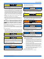
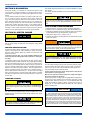
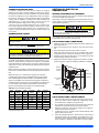
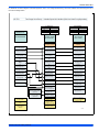
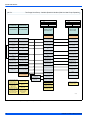
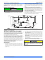
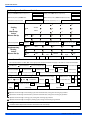
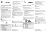
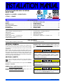
INSTALLATION MANUAL
R-410A OUTDOOR SPLIT-SYSTEM
HEAT PUMP
®
MODELS: 14.5 SEER - YHJF60/THJF60
5 TONS – 1 PHASE
LIST OF SECTIONS
GENERAL . . . . . . . . . . . . . . . . . . . . . . . . . . . . . . . . . . . . . . . . . . . . . .1
SAFETY . . . . . . . . . . . . . . . . . . . . . . . . . . . . . . . . . . . . . . . . . . . . . . . .1
UNIT INSTALLATION . . . . . . . . . . . . . . . . . . . . . . . . . . . . . . . . . . . . .2
INDOOR EXPANSION DEVICE . . . . . . . . . . . . . . . . . . . . . . . . . . . . . .5
EVACUATION . . . . . . . . . . . . . . . . . . . . . . . . . . . . . . . . . . . . . . . . . . .6
SYSTEM CHARGE . . . . . . . . . . . . . . . . . . . . . . . . . . . . . . . . . . . . . . .6
ELECTRICAL CONNECTIONS . . . . . . . . . . . . . . . . . . . . . . . . . . . . . 7
SYSTEM START-UP . . . . . . . . . . . . . . . . . . . . . . . . . . . . . . . . . . . . . 8
SYSTEM OPERATION . . . . . . . . . . . . . . . . . . . . . . . . . . . . . . . . . . . 11
INSTRUCTING THE OWNER . . . . . . . . . . . . . . . . . . . . . . . . . . . . . 11
WIRING DIAGRAM . . . . . . . . . . . . . . . . . . . . . . . . . . . . . . . . . . . . . 12
START UP SHEET . . . . . . . . . . . . . . . . . . . . . . . . . . . . . . . . . . . . . . 13
LIST OF FIGURES
Typical Installation with Required Clearances . . . . . . . . . . . . . . . . . . .2
Tubing Hanger . . . . . . . . . . . . . . . . . . . . . . . . . . . . . . . . . . . . . . . . . . .3
Underground Installation . . . . . . . . . . . . . . . . . . . . . . . . . . . . . . . . . . .4
Heat Protection . . . . . . . . . . . . . . . . . . . . . . . . . . . . . . . . . . . . . . . . . .4
Outdoor Unit Control Box - 14.5 SEER 60 Only . . . . . . . . . . . . . . . . . .7
Thermostat Wiring – Two-Stage Heat Pump Variable Speed Air Handler . . . . . . . . . . . . . . . . . . . . . . . . . . . . . . . . .8
Thermostat Wiring – Two-Stage Heat Pump Variable Speed Air Handler . . . . . . . . . . . . . . . . . . . . . . . . . . . . . . . . 9
CFM Selection Board . . . . . . . . . . . . . . . . . . . . . . . . . . . . . . . . . . . . 10
Heat Pump Flow Diagram . . . . . . . . . . . . . . . . . . . . . . . . . . . . . . . . . 11
Wiring Diagram - Single Phase - 14.5 SEER - 5 Ton . . . . . . . . . . . . 12
LIST OF TABLES
Maximum / Minimum Operating Limit Conditions . . . . . . . . . . . . . . . . .2
SECTION I: GENERAL
The outdoor units are designed to be connected to a matching indoor
coil with sweat connect lines. Sweat connect units are factory charged
with refrigerant for the smallest rated indoor coil plus 15 feet of field
supplied lines.
Matching indoor coils require a matching thermostatic expansion valve
(TXV) - refer to the Tabular Data Sheet or Technical Guide. The refrigerant charge may need to be changed for some indoor-outdoor unit
combinations, elevation differences, or total line lengths. Refer to Application Data covering “General Piping Recommendations and Refrigerant Line Length” (Part Number 247077).
SECTION II: SAFETY
This is a safety alert symbol. When you see this symbol on
labels or in manuals, be alert to the potential for personal
injury.
Understand and pay particular attention to the signal words DANGER,
WARNING, or CAUTION.
R-410A Saturation Properties . . . . . . . . . . . . . . . . . . . . . . . . . . . . . . . 7
CAUTION indicates a potentially hazardous situation, which, if not
avoided may result in minor or moderate injury. It is also used to
alert against unsafe practices and hazards involving only property damage.
Improper installation may create a condition where the operation of
the product could cause personal injury or property damage.
Improper installation, adjustment, alteration, service, or maintenance can cause injury or property damage. Refer to this manual
for assistance or for additional information, consult a qualified contractor, installer, or service agency.
This product must be installed in strict compliance with the
enclosed installation instructions and any applicable local, state,
and national codes including, but not limited to building, electrical,
and mechanical codes.
DANGER indicates an imminently hazardous situation, which, if not
avoided, will result in death or serious injury.
WARNING indicates a potentially hazardous situation, which, if not
avoided, could result in death or serious injury.
R-410A systems operate at higher pressures than R-22 systems. Do
not use R-22 service equipment or components on R-410A equipment. Service equipment Must Be Rated for R-410A.
835959-UIM-D-0814
835959-UIM-D-0814
INSPECTION
SECTION III: UNIT INSTALLATION
As soon as a unit is received, it should be inspected for possible damage during transit. If damage is evident, the extent of the damage
should be noted on the carrier’s delivery receipt. A separate request for
inspection by the carrier’s agent should be made in writing. Local Distributor can be contacted for more information.
LOCATION
Requirements For Installing/Servicing R-410A Equipment
•
Gauge sets, hoses, refrigerant containers, and recovery system
must be designed to handle the POE type oils, and the higher
pressures of R-410A.
Manifold sets should be 800 psig high side and 250 psig low side
with 550 psig low side restart.
All hoses must have a 700 psig service pressure rating.
Leak detectors should be designed to detect HFC refrigerant.
Recovery equipment (including refrigerant recovery containers)
must be specifically designed to handle R-410A.
Do not use an R-22 TXV.
A liquid-line filter drier is required on every unit.
•
•
•
•
•
•
LIMITATIONS
The unit should be installed in accordance with all National, State, and
Local Safety Codes and the limitations listed below:
1.
Limitations for the indoor unit, coil, and appropriate accessories
must also be observed.
The outdoor unit must not be installed with any duct work in the air
stream. The outdoor fan is the propeller type and is not designed
to operate against any additional external static pressure.
The maximum and minimum conditions for operation must be
observed to assure a system that will give maximum performance
with minimum service. Refer to the dry bulb (DB) and wet bulb
(WB) temperature limitations in Table 1.
The 2 stage units are not designed to operate with a low ambient
kit. The 2 stage models which can not operate with a low ambient
kit include YHJF and THJF models. Do not modify the control system of these models to operate with any kind of low ambient kit.
The maximum allowable line length for this product is 75 feet
2.
3.
4.
5.
.
TABLE 1: Maximum / Minimum Operating Limit Conditions
AIR TEMPERATURE AT
OUTDOOR COIL, °F
Min.
AIR TEMPERATURE AT
INDOOR COIL, °F
Max.
Min.
Max.
DB
Cool
DB
Heat
DB
Cool
DB
Heat
WB
Cool
DB
Heat
WB
Cool
DB
Heat
50
-10
115
75
57
501
72
80
1.
Operation below this temperature is permissible for a short period of
time, during morning warm-up.
1.
60” OVERHEAD
CLEARANCE
Before starting the installation, the suitability of the location for both the
indoor and outdoor units need to be checked. All required limitations
and clearances must be observed. The outdoor unit must have sufficient clearance for air entrance to the condenser coil, for air discharge,
and for service access as shown in Figure 1.
NOTICE
For multiple unit installations, units must be spaced a minimum of 24
inches apart (coil face to coil face).
If the unit is to be installed on a hot sun exposed roof or a paved
ground area that is seasonally hot, the unit should be raised sufficiently
above the roof or ground to avoid taking the accumulated layer of hot
air into the outdoor unit.
Provide adequate structural support.
ADD-ON REPLACEMENT/RETROFIT
When this unit is being used as a replacement for an R-22 unit, it is
required that the outdoor unit, indoor coil, and metering device all be
replaced. The following steps should be performed in order to insure
proper system operation and performance. Line-set change out is also
recommended.
1. Change-out of the indoor coil to an approved R-410A coil/ condensing unit combination with the appropriate metering device.
2. Change-out of the line-set when replacing an R-22 unit with an
R410-A unit is highly recommended to reduce cross-contamination
of oils and refrigerants.
3. If change-out of the line set is not practical, then the following precautions should be taken.
• Inspect the line set for kinks, sharp bends, or other restrictions,
and for corrosion.
• Determine if there are any low spots which might be serving as oil
traps.
• Flush the line set with a commercially available flush kit to
remove as much of the existing oil and contaminants as possible.
• Install a suction line filter-drier to trap any remaining contaminants, and remove after 50 hours of operation.
4. If the outdoor unit is being replaced due to a compressor burnout,
then installation of a 100% activated alumina suction-line filter drier
in the suction-line is required, in addition to the factory installed liquid-line drier. Operate the system for 10 hours. Monitor the suction
drier pressure drop. If the pressure drop exceeds 3 psig, replace
both the suction-line and liquid-line driers. After a total of 10 hours
run time where the suction-line pressure drop has not exceeded 3
psig, replace the liquid line drier, and remove the suction-line drier.
During the contamination removal procedure, never leave a suctionline drier in the system longer than 50 hours of run time.
MINIMUM 18” SERVICE
ACCESS CLEARANCE
ON ONE SIDE
THERMOSTAT
WEATHERPROOF
DISCONNECT
SWITCH
NEC CLASS 1 WIRING
NEC CLASS 2 WIRING
10” CLEARANCE
AROUND PERIMETER
TO FURNACE OR
AIR HANDLER
TERMINAL BLOCK
TO INDOOR COIL
NOTES:
ALL OUTDOOR WIRING MUST BE WEATHERPROOF.
MINIMUM 24” UNIT TO UNIT CLEARANCE.
CONTROL
ACCESS
PANEL
SEAL OPENING(S) WITH
PERMAGUM OR EQUIVALENT
A0167-001
FIGURE 1: Typical Installation with Required Clearances
2
Johnson Controls Unitary Products
835959-UIM-D-0814
GROUND INSTALLATION
The unit may be installed at ground level on a solid base that will not
shift or settle, causing strain on the refrigerant lines and possible leaks.
The unit must be installed in as level a position as possible while maintaining the clearances shown in Figure 1.
Normal operating sound levels may be objectionable if the unit is placed
directly under windows of certain rooms (bedrooms, study, etc.).
Condensate will drain from beneath the coil of the outdoor unit during
the defrost cycle. Normally this condensate may be allowed to drain
directly on the ground.
The outdoor unit should not be installed in an area where mud or ice
could cause personal injury. Remember that condensate will drip from
the unit coil during heat and defrost cycles and that this condensate
will freeze when the temperature of the outdoor air is below 32°F.
Elevate the unit sufficiently to prevent any blockage of the air entrances
by snow in areas where there will be snow accumulation. Check the
local weather bureau for the expected snow accumulation in your area.
Isolate the unit from rain gutters to avoid any possible wash out of the
foundation.
ROOF INSTALLATION
When installing units on a roof, the structure must be capable of supporting the total weight of the unit, including a pad, lintels, rails, etc.,
which should be used to minimize the transmission of sound or vibration into the conditioned space.
WALL MOUNT INSTALLATION
Care must be taken to mount the outdoor unit on a solid base that is
sloped to shed water, secure from settlement, and is isolated from the
structural foundation or walls to prevent sound and vibration transmission into the living space. In addition heat pump units must be elevated
above anticipated snow accumulation levels to allow for proper defrost
drainage and airflow.
On occasion, site conditions may require direct wall mounted brackets
to be used to locate and support the outdoor unit. In these applications,
care must be taken to address unit base pan support, structural integrity, safe access and serviceability, as well as the possible sound and
vibration transmission into the structure. These applications are best
served by a properly engineered solution.
UNIT PLACEMENT
NOTICE
Heat pumps will defrost periodically resulting in water drainage. The
unit should not be located where water drainage may freeze and create a hazardous condition - such as sidewalks and steps.
1.
2.
3.
4.
Provide a base in the pre-determined location.
Remove the shipping carton and inspect for possible damage.
Ensure that compressor tie-down bolts remain tightened.
Position the unit on the base provided.
LIQUID LINE FILTER-DRIER
NOTICE
Replacements for the liquid line drier must be exactly the same as
marked on the original factory drier. See Source 1 for O.E.M. replacement driers.
R-410A Filter-Drier Source 1 Part No.
Apply with Models
S1-404101
All
PIPING CONNECTIONS
Never install a suction-line filter drier in the liquid line of an R-410A
system. Failure to follow this warning can cause a fire, injury or death.
This system uses R-410A refrigerant only, which operates at higher
pressures than R-22. No other refrigerant than R-410A may be used
in this system. Gauge sets, hoses, refrigerant containers, and recovery system must be designed to handle R-410A. If you are unsure,
consult the equipment manufacturer.
The outdoor unit must be connected to the indoor coil using field supplied refrigerant grade copper tubing that is internally clean and dry.
Units should be installed only with the tubing sizes for approved system
combinations as specified in Tabular Data Sheet. The charge given is
applicable for total tubing lengths up to 15 feet. See Application Data
Part Number 247077 for installing tubing of longer lengths and elevation
differences.
NOTICE
Using a larger than specified line size could result in oil return problems. Using too small a line will result in loss of capacity and other
problems caused by insufficient refrigerant flow. Slope horizontal
vapor lines at least 1" every 20 feet toward the outdoor unit to facilitate proper oil return.
PRECAUTIONS DURING LINE INSTALLATION
1. Install the lines with as few bends as possible. Make sure there is no
damage done to the couplings or kink made in the tubing. Use clean
hard drawn copper tubing where no appreciable amount of bending
around obstruction is necessary. If soft copper must be used, make
sure to avoid sharp bends which may cause a restriction.
2. Ensure that the lines are installed so they do not obstruct service
access to the coil, air handling system, or filter.
3. Make sure to isolate the refrigerant lines to minimize noise transmission from the equipment to the structure.
4. Make sure to insulate the vapor line with a minimum of 1/2” foam
rubber insulation (Armaflex or equivalent). Make sure to insulate the
liquid lines which are exposed to direct sunlight and/or high temperatures.
5. Tape and suspend the refrigerant lines as shown in Figure 2. DO
NOT allow tube metal-to-metal contact.
SHEET METAL HANGER
The heat pumps have a solid core bi-flow filter/drier located on the liquid
line.
LIQUID
LINE
INCORRECT
Failure to use the same as the original factory drier or using a substitute drier or a granular type may result in damage to the equipment.
CORRECT
TAPE
INSULATED VAPOR LINE
A0151-001
FIGURE 2: Tubing Hanger
Johnson Controls Unitary Products
3
835959-UIM-D-0814
6. Use PVC piping as a conduit for all underground installations as
shown in Figure 3. Keep buried lines as short as possible to minimize the build up of liquid refrigerant in the vapor line during long
periods of shutdown.
7. Pack fiberglass insulation and a sealing material such as permagum
around refrigerant lines where they penetrate a wall to reduce vibration and to retain some flexibility.
8. See Application Data Part Number 247077 for additional piping information.
LIQUID LINE
PVC
CONDUIT
TO INDOOR COIL
TO OUTDOOR UNIT
INSULATED
VAPOR LINE
CAP
A0153-001
FIGURE 4: Heat Protection
Connect the refrigerant lines using the following procedure:
A0152-001
FIGURE 3: Underground Installation
PRECAUTIONS DURING BRAZING OF LINES
All outdoor unit and evaporator coil connections are copper-to-copper
and should be brazed with a phosphorous-copper alloy material such
as Silfos-5 or equivalent. DO NOT use soft solder. The outdoor units
have reusable service valves on both the liquid and vapor connections.
The total system refrigerant charge is retained within the outdoor unit
during shipping and installation. The reusable service valves are provided to evacuate and charge per this instruction.
Serious service problems can be avoided by taking adequate precautions to assure an internally clean and dry system.
Dry nitrogen should always be supplied through the tubing while it is
being brazed, because the temperature required is high enough to
cause oxidation of the copper unless an inert atmosphere is provided.
The flow of dry nitrogen should continue until the joint has cooled.
Always use a pressure regulator and safety valve to insure that only
low pressure dry nitrogen is introduced into the tubing. Only a small
flow is necessary to displace air and prevent oxidation.
PRECAUTIONS DURING BRAZING SERVICE VALVE
Precautions should be taken to prevent heat damage to service valve
by wrapping a wet rag around it as shown in Figure 4. Also, all painted
surfaces, insulation, and the plastic base should be protected during
brazing. After brazing, joint should be cooled with wet rag.
This is not a backseating valve. The service access port has a valve
core. Opening or closing valve does not close service access port.
If the valve stem is backed out past the chamfered retaining wall, the
O-ring can be damaged causing leakage or system pressure could
force the valve stem out of the valve body possibly causing personal
injury.
Valve can be opened by removing the plunger cap and fully inserting a
hex wrench into the stem and backing out counter-clockwise until valve
stem just touches the chamfered retaining wall.
1. Remove the cap and Schrader core from both the liquid and vapor
valve service ports at the outdoor unit. Connect low pressure nitrogen to the liquid line service port.
2. Braze the liquid line to the liquid valve at the outdoor unit. Be sure to
wrap the valve body with a wet rag. Allow the nitrogen to continue
flowing. Refer to the Tabular Data Sheet for proper liquid line sizing.
3. Go to SECTION IV, and accomplish the TXV Installation procedure.
Do not install any coil in a furnace which is to be operated during the
heating season without attaching the refrigerant lines to the coil. The
coil is under 30 to 35 psig inert gas pressure which must be released
to prevent excessive pressure build-up and possible coil damage.
4. Braze the liquid line to the evaporator liquid connection. Ensure that
nitrogen is flowing through the evaporator coil to prevent oxidation
during brazing procedure.
5. Remove the split rubber grommet from the vapor connection at the
indoor coil. Braze the vapor line to the evaporator vapor connection.
After the connection has cooled, place the rubber grommet back into
the mounting position. Refer to the Tabular Data Sheet for proper
vapor line sizing.
6. Protect the vapor valve with a wet rag, and braze the vapor line connection to the outdoor unit. Ensure that the nitrogen flow is exiting
the system from the vapor service port connection. After this connection has cooled, remove the nitrogen source from the liquid fitting
service port.
7. Replace the Schrader core in the liquid and vapor valves.
Never attempt to repair any brazed connections while the system is
under pressure. Personal injury could result.
NOTICE
Refrigeration piping and indoor coil can be pressurized to 250 psig
with dry nitrogen and leak tested with a bubble type leak detector.
Then release the nitrogen charge.
Do not use the system refrigerant from the outdoor unit to purge or
leak test the system.
8. Leak test and repair leaks in all refrigerant piping connections including the service port flare caps. DO NOT OVERTIGHTEN caps.
Torque caps between 40 and 60 inch - lbs. maximum.
9. Evacuate the vapor line, the evaporator, and the liquid line to 500
microns or less in accordance with the EVACUTATION procedures.
4
Johnson Controls Unitary Products
835959-UIM-D-0814
Do not connect manifold gauges unless trouble is suspected. Approximately 3/4 ounce of refrigerant will be lost each time a standard manifold gauge is connected.
10.Release the refrigerant charge into the system in accordance with
the SYSTEM CHARGE procedures. Open the liquid line base valve
first and let pressures equalize. Then, open the suction line base
valve. When opening either valve, use an appropriate hex head
wrench and back seat the base valve by turning it counter clockwise
until it stops against the chamfered retaining wall, and then turn it
back 1/8 turn. If the service valve is a ball valve, use an adjustable
end wrench to turn valve stem one-quarter turn counterclockwise to
open. Do not overturn (or the valve stem may break or become damaged).
11.To prevent leaks, replace base valve caps finger tight, and then
tighten the cap an additional 1/12 turn (1/2 hex flat).
12.Replace cap on service ports. Do not remove the flare caps from the
service ports except when necessary for servicing the system.
13. See “System Charge” section for checking and recording system
charge.
3. Before the suction line from the outdoor unit is brazed to the indoor
coil suction line, remove and discard black plastic cap from equalizer
fitting on the indoor coil suction line.
4. Loosen and remove distributor cap seal.
NOTICE
Do not install TXV onto distributor assembly until field supplied liquid
line is brazed onto the indoor coil liquid line and cooled.
5. Install the TXV to the distributor assembly by hand tightening, and
then turn fitting an additional 1/4 turn to seal. Do not overtighten fittings.
Do not use slip joint pliers. Damage and distortion of distributor can
prevent proper seal. Use appropriate sized adjustable end wrench.
6. Install the liquid line to the top of the TXV using the liquid line fitting
which is supplied with the indoor coil. Hand modify the liquid line to
align with casing opening. Hand tighten the liquid line on the TXV,
and tighten an additional 1/4 turn to seal.
SECTION IV: INDOOR EXPANSION DEVICE
THERMOSTATIC EXPANSION VALVE (TXV) INSTALLATION
Before accomplishing the following procedures, verify the proper TXV
kit to be installed on the coil. Refer to supplied Tabular Data Sheet for
specific TXV kit and indoor coil match up.
The following are basic steps for installation of a TXV kit. For detailed
instructions, refer to the Installation Instructions accompanying the TXV
kit.
A schrader valve core MUST NOT be installed in the equalizer fitting
when the TXV kit is installed. Poor system performance or system
failure could result.
NOTICE
Do not install TXV equalizer line onto equalizer fitting nor the TVX
bulb onto the suction vapor line until field supplied suction line is
brazed onto the indoor coil suction line and cooled.
Install TXV kit as follows:
1. Relieve nitrogen holding charge by depressing the Schrader valve
stem located in the end of the suction line. After nitrogen holding
charge is completely discharged, cut off the spundown copper end of
the suction line to allow installation of the field supplied suction line.
In all cases, do not mount the TXV bulb until after the suction line is
brazed and has had sufficient time to cool.
Dry nitrogen should always be supplied through the tubing while it is
being brazed, because the temperature is high enough to cause oxidation of the copper unless an inert atmosphere is provided. The flow
of dry nitrogen should continue until the joint has cooled. Always use
a pressure regulator and safety valve to insure that only low pressure
dry nitrogen is introduced into the tubing. Only a small flow is necessary to displace air and prevent oxidation.
7. Install the TXV equalizer line onto the equalizer fitting of the suction
line. Hand tighten the 1/4” SAE nut to the equalizer fitting, and
tighten an additional 1/3 turn to seal.
NOTICE
The TXV bulb is to be installed on the suction line near the equalizer
line, using the two bulb clamps furnished with the TXV assembly kit.
The bulb is to make maximum contact. The TXV installation instruction provide an illustration of proper bulb location.
8. Install the TXV bulb to the suction line near the equalizer line, using
the bulb clamp(s) furnished with the TXV assembly kit. Ensure the
bulb is making maximum contact.
a. Install the bulb on the suction line near the equalizer line with
the bulb horizontal to the suction line. On a suction line under
7/8” Outside Diameter (O.D.), install the bulb on top of the
line. On a suction line 7/8” O.D. or larger, install the bulb at
about the 2 or 10 o'clock position.
b.
If bulb must be installed vertically to the suction line, position
the bulb at least 16 inches (40.6 cm) from any bend and on
the opposite side of the bend plane. Positioned the bulb with
the bulb tail at the top, so that the bulb acts as a reservoir.
c.
Use thermal insulation provided to protect the bulb from the
effect of the surrounding ambient temperature. Cover the
bulb completely to insulate from air-stream.
2. Slide indoor coil out of cabinet far enough to gain access to equalizer fitting on the suction line.
NOTICE
All connections to be brazed are copper-to-copper and should be
brazed with a phosphorous-copper alloy material such as Silfos-5 or
equivalent. Soft solder is NOT to be used.
Johnson Controls Unitary Products
9. Slide indoor coil back into cabinet.
10.Leak test system after outdoor unit is connected.
5
835959-UIM-D-0814
SECTION V: EVACUATION
During this process, it is necessary to evacuate the system to 500
microns or less. If a leak is suspected, a dry nitrogen charge is used to
locate leak(s). After repairing any leaks, another leak test is to be performed.
To verify that the system has no leaks, the system is held under a vacuum by closing the valve to the vacuum pump suction isolating the
pump. The micron gauge is observed for a few minutes. If the micron
gauge indicates a steady and continuous rise, it is an indication of a
leak. If the gauge shows a rise, then levels off after a few minutes and
remains fairly constant above 500 microns, it is an indication that the
system is leak free but still contains moisture and may require further
evacuation. Proper system evacuation requires the micron gauge to
indicate a vacuum holding below 500 microns for several minutes.
SECTION VI: SYSTEM CHARGE
Refrigerant charging should only be carried out by a qualified air conditioning contractor.
To ensure that your unit performs at the published levels, it is important
that the indoor airflow is determined and refrigerant charge added
accordingly.
MEASURE INDOOR AIR FLOW
To determine rated air flow for a specific match, consult the technical literature at www.upgnet.com. When attempting to match this air flow,
select the lowest possible speed tap, measure the actual flow, and
adjust as necessary.
To measure actual air flow, it is not an acceptable method to just
check the jumper pin setting tables and to assume 0.5” static pressure drop.
To determine indoor air flow, first measure the static pressure with a
manometer between the filter and blower. On a single-piece air handler,
take a second reading after the coil. On a furnace or modular air handler, take the second reading after the heat exchanger, but before the
indoor coil. Add the negative return static to the positive supply static to
determine the system total static pressure. Treat the negative return
static as a positive pressure (even though it is a negative reading). If
there is static pressure on the blower (i.e. -.10) return, add it to a supply
static (.40) which equals a (.50) total system static pressure. Compare
this value to the table for the indoor unit's static pressure vs. CFM or to
a curve chart.
CHARGING THE UNIT
R-410A refrigerant cylinders are rose colored, and have a dip tube
which allows liquid to flow out of the cylinder in the Upright Position. Always charge the system slowly with the tank in the upright
position.
The factory charge in the outdoor unit includes enough charge for the
unit, 15 ft. (4.6 m) of refrigerant piping, and the smallest indoor coil/air
handler match-up. Some indoor coil/air handler matches may require
additional charge.
Compressor damage will occur if system is improperly charged. On
new system installations, charge system per tabular data sheet for
the matched coil and follow guidelines in this instruction.
6
See Tabular Data Sheet provided in unit Customer Booklet for charge
requirements.
The “TOTAL SYSTEM CHARGE” must be permanently marked on the
unit data plate.
Do not leave the system open to the atmosphere. Unit damage
could occur due to moisture being absorbed by the POE oil in the
system. This type of oil is highly susceptible to moisture absorption.
TOTAL SYSTEM CHARGE DETERMINED
1. Determine outdoor unit factory charge from Tabular Data Sheet.
2. Determine indoor coil adjustment (if any) from Tabular Data Sheet.
3. Calculate the additional charge for refrigerant piping using the Tabular Data Sheet if line length is greater than 15 feet (4.6 m).
4. Total system charge = item 1 + item 2 + item 3.
5. Permanently mark the unit data plate with the total amount of refrigerant in the system.
DO NOT attempt to pump “Total System Charge” into outdoor unit for
maintenance, service, etc. This may cause damage to the compressor and/or other components. The outdoor unit only has enough volume for the factory charge, not the “Total System Charge”.
IT IS UNLAWFUL TO KNOWINGLY VENT, RELEASE OR DISCHARGE REFRIGERANT INTO THE OPEN AIR DURING REPAIR,
SERVICE, MAINTENANCE OR THE FINAL DISPOSAL OF THIS
UNIT.
CHARGING IN COOLING MODE
The unit includes heating charging charts and cooling charging charts.
All units include a subcooling charging chart for cooling. If a charging
chart is not on the unit, then it can be obtained at www.upgnet.com
under the Heating Service Condenser Guide.
Cooling charts should not be used to charge the unit. They are reference charts for servicing the unit.
After the unit has been serviced, collect the charge and weigh it
back in according to the directions.
When charging a unit in cooling mode, the charge MUST be weighed in.
Charging by any other method, such as superheat, subcooling, cooling
charging charts, feeling the line set, etc is not acceptable. Most heat
pumps are sensitive to charge in heating, requiring more charge, so
charging by an unacceptable method will cause the unit to perform
poorly in heating mode.
NOTICE
This method is for systems that only have interconnecting lines. If
any other objects that adjust the charge levels are placed between
the indoor and outdoor units (example: a refrigerant flow meter), then
before adding charge, the device must first be removed. Follow the
steps above. Run the system in both cooling and heating mode and
record the high side pressure in each mode. Then insert the device
and charge the system by matching the same high side pressure in
both heating and cooling as that value recorded without the device. It
is not acceptable to add a pre-determined charge amount listed by
the device manufacturer nor is it acceptable to use any other method.
Johnson Controls Unitary Products
835959-UIM-D-0814
CHARGING IN HEATING MODE
If charging in heating mode, there are two methods for charging:
Weighing in the charge is the best method for ensuring the unit performs as rated. However, if a device is installed in the line set that alters
the amount of refrigerant, such as a refrigerant flow meter, then the better method for charging is to match the liquid pressure from the heating
charging chart (if available) or heating service data (available from
wwwupgnet.com). If no such device exists in the line set, then the
method is acceptable if weighing in the charge is not an option.
SECTION VII: ELECTRICAL
CONNECTIONS
GENERAL INFORMATION & GROUNDING
Check the electrical supply to be sure that it meets the values specified
on the unit nameplate and wiring label.
Power wiring, control (low voltage) wiring, disconnect switches and over
current protection must be supplied by the installer. Wire size should be
sized per NEC requirements.
If servicing a unit for low heating performance and you find that you
have to add a significant amount of charge (ex: 20-30 ounces) in order
to match the published liquid pressures, the unit will NOT be overcharged in cooling. Heat pumps are sensitive to charge in heating, but
not in cooling.
All field wiring must USE COPPER CONDUCTORS ONLY and be
in accordance with Local, National, Fire, Safety & Electrical Codes.
This unit must be grounded with a separate ground wire in accordance with the above codes.
CHARGING WITH GAUGES
The complete connection diagram and schematic wiring label is located
on the inside surface of the unit control box cover.
Refrigerant charging should only be carried out by a qualified air conditioning contractor.
Do not charge a heat pump in cooling mode with gauges or charging
charts or any other method other than weighing in the charge.
Compressor damage will occur if system is improperly charged. On
new system installations, charge system per tabular data sheet for
the matched coil and follow guidelines in this instruction.
However for servicing a heat pump unit, the charging charts are an
acceptable troubleshooting method, but when the servicing is completed, the charge should be reclaimed and weighed in (to guarantee
optimal performance in heating mode). If servicing in heating mode, the
charge does not have to be reclaimed if the liquid pressures match the
published values.
FIELD CONNECTIONS POWER WIRING
1. Install the proper size weatherproof disconnect switch outdoors and
within sight of the unit.
2. Remove the screws from the control box cover and remove from
unit.
3. Run power wiring from the disconnect switch to the unit.
4. Route wires from disconnect through the reversible high voltage
conduit plate and then into the unit control box shown in Figures 5.
5. Install the proper size time-delay fuses or circuit breaker, and make
the power supply contactor connections.
6. Energize the crankcase heater if equipped to save time by preheating the compressor oil while the remaining installation is completed.
Defrost
Control
Board
Before measuring the pressures, use the method above to check the air
flow and then consult the table and match the liquid pressure to that air
flow.
Relay
Transformer
Before servicing a unit, confirm that your gauges are accurate by
comparing the gauges against a calibrated pressure gauge that has
been calibrated against a national standard. If a calibrated pressure
gauge is not available, place a R-410A virgin refrigerant container in a
conditioned space long enough to come to temperature equilibrium with
the surroundings. Then measure the temperature of the air and the
pressure of the refrigerant and compare it to the following table:
Contactor
Low Voltage
Box
Snap Bushing
:
Conduit
Plate
TABLE 2: R-410A Saturation Properties
Capacitor
Temp
(°F)
Pressure
(Psig)
Temp
(°F)
Pressure
(Psig)
Temp
(°F)
Pressure
(Psig)
40
119
75
218
110
365
FIGURE 5: Outdoor Unit Control Box
45
130
80
236
115
391
FIELD CONNECTIONS CONTROL WIRING
50
143
85
255
120
418
1.
55
156
90
274
125
447
60
170
95
295
130
477
65
185
100
317
70
201
105
341
If the gauges are correct, then measure the pressures using both the
cooling and heating charts.
2.
3.
4.
5.
Johnson Controls Unitary Products
Ground Lug
A0195-001
Route low voltage wiring through the snap bushing in the low voltage box as shown in Figure 5. Make low voltage wiring connections inside the low voltage box per Figures 6 & 7.
The complete connection diagram and schematic wiring labels are
located on the inside surface of the unit control box cover.
Replace the control box cover removed in Step 2 of the “Field Connections Power Wiring” procedures.
All field wiring to be in accordance with national electrical codes
(NEC) and/or local city codes.
Mount the thermostat about 5 ft. above the floor, where it will be
exposed to normal room air circulation. Do not place it on an outside wall or where it is exposed to the radiant effect from exposed
glass or appliances, drafts from outside doors or supply air grilles.
7
835959-UIM-D-0814
6.
Route the 24-volt control wiring (NEC Class 2) from the outdoor
unit to the indoor unit and thermostat.
The HUMIDISTAT jumper must be placed on “YES” if a dehumidistat is
installed.
NOTICE
CFM SELECTION BOARD
To eliminate erratic operation, seal the hole in the wall at the thermostat with permagum or equivalent to prevent air drafts affecting the
operation of in the thermostat.
A Start Assist Kit is available and recommended for long line set
applications or in areas of known low voltage problems.
TAP SELECTION
DEHUMIDIFICATION CONTROL (Typical)
A dehumidification control accessory 2HU16700124 may be used with
variable speed air handlers or furnaces in high humidity areas. This
control works with the variable speed indoor unit to provide cooling at a
reduced air flow, lowering evaporator temperature and increasing latent
capacity. The humidistat in this control opens the humidistat contacts on
humidity rise. To install, refer to instructions packaged with the accessory and Figures 6 & 7. Prior to the installation of the dehumidification
control, the humidistat jumper must be set to “YES”.
During cooling, if the relative humidity in the space is higher than the
desired set point of the dehumidification control, the variable speed
blower motor will operate at lower speed until the dehumidification control is satisfied. A 40-60% relative humidity level is recommended to
achieve optimum comfort.
If a dehumidification control is installed, it is recommended that a minimum air flow of 325 CFM/ton be supplied at all times.
D
C
B
A
D
C
B
A
COOL
HEAT
ADJ
DELAY
REMOVE FOR
HEAT PUMP
HUMIDISTAT
A0196-001
FIGURE 6: CFM Selection Board
SECTION VIII: SYSTEM START-UP
ENERGIZE CRANKCASE HEATER
In order to energize the crankcase heater, set the indoor cooling thermostat to the OFF position. Close the line power disconnect to the unit.
To see connection diagrams of all UPG equipment, the “Low Voltage
System Wiring” document is available online at www.upgnet.com in the
Product Catalog Section.
An attempt to start the compressor without at least 8 hours of
crankcase heat will damage the compressor.
INDOOR CUBIC FEET PER MINUTE (CFM) SELECTION BOARD SETTINGS (Typical)
WITH POWER TO UNIT AND THERMOSTAT IN COOLING POSITION:
For proper system operation the CFM Selection Board jumpers must be
set properly.
1.
Refer to the Tabular Data Sheet for the recommended air flow settings
for each size condensing unit.
2.
Set the cooling speed per the instructions for the air handler or furnace
by selecting the correct COOL and ADJUST (or ADJ) taps. Verify the
airflow using the LED display on the CFM selection board.
3.
The HEAT PUMP jumper MUST be placed on “YES” or “HP” (depending on which control board is present) for proper system operation.
4.
8
In the cooling cycle, discharge gas is pumped to the outdoor coil
which is the condenser. The indoor coil is the evaporator.
If fan switch is in the ON position, a circuit is made through blower
relay to provide continuous blower operation.
With fan switch is in the AUTO position, a circuit is made from thermostat cooling contact through blower relay to provide blower
operation.
System will cycle with thermostat demand to provide cooling as
needed.
Johnson Controls Unitary Products
835959-UIM-D-0814
For additional connection diagrams of all UPG equipment, refer to “Low Voltage System Wiring.” Document available online at www.upgnet.com in
the Product Catalog Section.
HP 27A
Two Stage Heat Pump – Variable Speed Air Handler (With Hot Heat Pump Operation)
ID MODELS
AHV
OD MODELS
*HJF60
MV
THERMOSTAT
VARIABLE SPEED
AIR HANDLER
TWO STAGE
HEAT PUMP
VARIABLE SPEED
AIR HANDLER CONTROL
YORKGUARD VI
CONTROL
C
24 – Volt Common
COM
24 – Volt Common
C
24 – Volt Common
Y1
First Stage Compressor
Y1
Single Stage Compressor
Y1
Single Stage Compressor
R
24 – Volt Hot
R
24 – Volt Hot
R
24 – Volt Hot
G
Fan
G
Fan
Fault
W1
First Stage Aux. Heat
W1 OUT
First Stage Heat
W2
Second Stage Aux. Heat
W2 OUT
Second Stage Heat
S1-THSU32HP7b
W3
Third Stage Heat
Y/Y2
Second or Full
Stage Compressor
O
Reversing Valve
Energized in Cool
Y2
Y2
Second Stage
Stage Compressor
Second
Compressor
W2
Second Stage Heat
X/L
Malfunction Light
W1/O/B
First Stage Heat
Y2 OUT
Second Stage Compressor
O
Reversing Valve
Energized in Cool
X/L
Malfunction Light
Y2
Second Stage Compressor
HUM
W
Auxiliary Heat
DHUM
HUM
DehumidificationOpen on Humidity Rise
BSG
Bonnet Sensor
24VAC Humidifier Relay
(Optional)
HUM OUT
(24 VAC out)
BS
Bonnet Sensor
24VAC Electronic
Air Cleaner Relay
(Optional)
EAC(24 VAC out)
Electronic Air Cleaner
Jumper 1 must be set
to “HEATPUMP”
Jumper 2 must be set
to “O”
Setup Step 50 “Dual
Fuel” must be set
“External”
Move the MODE
jumper to “HP”
Move the HUM STAT
jumper to “YES”
if humidistat is to be used.
Refer to AH documentation
for W1 and W2 electric
heat staging options.
Change Hot Heat Pump
jumper on the heat pump
control to “ON”
A013-001
FIGURE 7: Thermostat Wiring – Two-Stage Heat Pump - Variable Speed Air Handler
Johnson Controls Unitary Products
9
835959-UIM-D-0814
HP 27C
Two Stage Heat Pump - Variable Speed Air Handler (With Hot Heat Pump Operation)
ID MODELS
OD MODELS
*HJF60
AHV
MV
THERMOSTAT
THERMOSTAT
*PP32U70124
S1-THPU32HP7b
VARIABLE SPEED
AIR HANDLER
TWO STAGE
HEAT PUMP
VARIABLE SPEED
AIR HANDLER CONTROL
YORKGUARD VI
CONTROL
C
24 – Volt Common
C
24 – Volt Common
COM
24 – Volt Common
C
24 – Volt Common
Y
First Stage Compressor
Y1
First Stage Compressor
Y1
Single Stage Compressor
Y1
Single Stage Compressor
R
24 – Volt Hot
(Heat XFMR)
R
24 – Volt Hot
R
24 – Volt Hot
R
24 – Volt Hot
G
Fan
G
Fan
G
Fan
E
Emergency Heat
RC
24 – Volt Hot
(Cool XFMR)
W3/Aux
Auxiliary Output
O/B
Reversing Valve
W1/O/B
First Stage Heat
W1
First Stage Aux. Heat
W1 OUT
First Stage Heat
W2
Second Stage Aux. Heat
W2 OUT
Second Stage Heat
Y/Y2
Second or Full
Stage Compressor
O
Reversing Valve
Energized in Cool
L
Malfunction Light
X/L
Malfunction Light
Y2 OUT
Second Stage Compressor
O
Reversing Valve
Energized in Cool
X/L
Malfunction Light
Y2
Second Stage Compressor
Y2
Second Stage Compressor
Y2
Second Stage Compressor
AUX
Auxiliary Heat
W2
Second Stage Heat
W
Auxiliary Heat
External Humidistat
(Optional)
Open on Humidity Rise
Thermostat Installer Setup
0170-System Type
must be set to 12
3 Heat/2 Heat Pump
Thermostat Installer Setup
0190-Changeover Valve
must be set to 0
O/B terminal
Energized in Cooling
Thermostat Installer Setup
0200-Backup Heat Source
must be set to 0
Heat Pump Backup Heat
Source is Electric
Jumper 1 must
be set to “ELEC”
Jumper 2 must be
set to “O”
Jumper 3 must be
set to “HP”
Can use “W3/Aux”
output to control
dehumidification
if desired
24VAC Humidifier Relay
(Optional)
24VAC Electronic
Air Cleaner Relay
(Optional)
HUM
DehumidificationOpen on Humidity Rise
BSG
Bonnet Sensor
HUM OUT
(24 VAC out)
BS
Bonnet Sensor
EAC(24 VAC out)
Electronic Air Cleaner
Move the MODE
jumper to “HP”
Move HUM STAT
jumper to “YES”
if humidistat is to be used.
Refer to AH documentation
for W1 and W2 electric
heat staging options.
Change Hot Heat Pump
jumper on the heat pump
control to “ON”
A014-001
FIGURE 8: Thermostat Wiring – Two-Stage Heat Pump - Variable Speed Air Handler
10
Johnson Controls Unitary Products
835959-UIM-D-0814
SECTION IX: SYSTEM OPERATION
For more information on the control operation, refer to the “OPERATION INSTRUCTIONS - DEMAND DEFROST CONTROL BOARD”
publication.
REQUIRED CONTROL SETUP
The following steps must be taken at the time of installation to insure
proper system operation.
1. Consult system wiring diagram to determine proper thermostat wiring for your system.
2. Verify that the factory set the defrost curve selection jumper at the
number “1” pin position on the defrost control board.
3. If hot heat pump configuration is desired, change HOT HEAT PUMP
jumper to ON position. This setting MUST be set on the defrost
board.
4. If installation includes a fossil fuel furnace, change FUEL jumper to
ON position. This setting MUST be set on the defrost board.
5. Set low temperature cutout (LTCO), balance point (BP), switch point
(SP), and Y2 Lock jumpers as desired. These settings may be modified by communicating thermostat.
6. Verify proper system functionality. Confirm room thermostat operation including fault code display capability.
7. Upon completion of installation, verify that no fault codes are stored
in memory. Clear the fault code memory if necessary.
FIELD CONNECTED LINE
INDOOR COIL
OUTDOOR
COIL
4-WAY
REVERSING
VALVE
.
SUCTION
ACCUMULATOR
COMPRESSOR
FLOW RATER
(Cooling)
LIQUID
SENSOR
FILTER DRYER
(Solid core)
FLOW RATER
(Heating)
FIELD CONNECTED LINE
COOLING CYCLE FLOW
A018-001
HEATING CYCLE FLOW
FIGURE 9: Heat Pump Flow Diagram
SECTION X: INSTRUCTING THE OWNER
Assist owner with processing warranty cards and/or online registration.
Review Owners Guide and provide a copy to the owner and guidance
on proper operation and maintenance. Instruct the owner or the operator how to start, stop and adjust temperature setting.
When applicable, instruct the owner that the compressor is equipped
with a crankcase heater to prevent the migration of refrigerant to the
compressor during the OFF cycle. The heater is energized only when
the unit is not running. If the main switch is disconnected for long periods of shut down, do not attempt to start the unit until 8 hours after the
switch has been connected. This will allow sufficient time for all liquid
refrigerant to be driven out of the compressor.
2.
3.
4.
5.
The outdoor fan motor is permanently lubricated and does not
require periodic oiling.
If the coil needs to be cleaned, it should be washed with Calgon
Coilclean (mix one part Coilclean to seven parts water). Allow
solution to remain on coil for 30 minutes before rinsing with clean
water. Solution should not be permitted to come in contact with
painted surfaces.
Refer to the furnace or air handler instructions for filter and blower
motor maintenance.
The indoor coil and drain pan should be inspected and cleaned
regularly to prevent odors and assure proper drainage.
The installer should also instruct the owner on proper operation and
maintenance of all other system components.
MAINTENANCE
1.
Dirt should not be allowed to accumulate on the outdoor coils or
other parts in the air circuit. Clean as often as necessary to keep
the unit clean. Use a brush, vacuum cleaner attachment, or other
suitable means.
Johnson Controls Unitary Products
IT IS UNLAWFUL TO KNOWINGLY VENT, RELEASE OR DISCHARGE REFRIGERANT INTO THE OPEN AIR DURING
REPAIR, SERVICE, MAINTENANCE OR THE FINAL DISPOSAL
OF THIS UNIT.
SUBCOOLING CHARGE TABLE IS ON THE UNIT RATING PLATE.
11
835959-UIM-D-0814
SECTION XI: WIRING DIAGRAM
DANGER - SHOCK HAZARD
COLOR CODE
LEGEND
TURN OFF ELECTRICAL POWER BEFORE
SERVICING TOPREVENT POSSIBLE DAMAGE
TO THE EQUIPMENT AND POSSIBLE
PERSONAL INJURY.
BLK - BLACK
BLK/PNK BLACK/PINK BLU - BLUE
BRN - BROWN
BLU/YEL BLUE/YELLOW
BRN/PNK BROWN/PINK
BRN/WHT BROWN/WHITE
GRN - GREEN
GRY - GREY
ORG - ORANGE
PUR - PURPLE
RED - RED
WHT - WHITE
YEL - YELLOW
Y/B - YEL/BLK
AS - AMBIENT SENSOR
CAP - CAPACITOR
COMP - COMPRESSOR
CC - CONTACTOR COIL
CCH - CRANKCASE HEATER
DS - DISCHARGE SENSOR
HPS - HIGH PRESS SWITCH
IR - ISOLATION RELAY
LS - LIQUID SENSOR
LPS - LOW PRESS SWITCH
OFM - OUTDOOR FAN MOTOR
RV - REVERSING VALVE
SC - START CAPACITOR
SOL - SOLENOID
SR - START RELAY
XFRM - TRANSFORMER
CAUTION
TO PREVENT ELECTRICAL SHOCK OPEN
REMOTE DISCONNECT SO ELECTRICAL
SUPPLY TO AIR CONDITIONER IS SHUT OFF.
1 COMPONENTS SHOWN IN DASHED
LINES ARE OPTIONAL.
2 DUAL CAPACITOR SHOWN. SEPARATE
CAPACITORS MAY BE USED ON ACTUAL
UNIT.
3 WIRING MUST CONFORM TO
NATIONAL AND LOCAL CODES.
4 IF ANY OF THE ORIGINAL WIRE
SUPPLIED WITH THIS UNIT MUST BE
REPLACED, IT MUST BE REPLACED
WITH TYPE 105°C. THERMOPLASTIC
OR ITS EQUIVALENT.
5 WHERE POWER SUPPLY HAS ONE (1) 230
VOLT CONDUCTOR AND ONE (1)
NEUTRAL CONDUCTOR. CONNECT L2 OF
CONTACTOR TO NEUTRAL.
HIGH VOLTAGE FACTORY WIRING
LOW VOLTAGE FACTORY WIRING
OPTIONAL WIRING
FIELD WIRING, LINE VOLTAGE
AS
LS
FAN MOTOR
RED
R
LPS
CC
W1 OUT
W2 OUT
BRN
GRY
BS
Y2 OUT
BLU
YEL/BLK
BSG
R
RED
YEL/BLK
X/L
PUR
O
W
WHT
ORG
C
Y1
YEL
M
HPS
BLK
ORG
T1
BRN/PNK
C
BLK
BLK
CONTACTOR
HPS
RV
R
USE COPPER
CONDUCTORS
ONLY
XFMR
RED
L1
BLK
L2
DIS
RV
RED
T2
DISG
RVG
BLK
BRN/PNK
BRN
RED
C
WHT
LPS
BLK
S
DEFROST CONTROL
LPS
BLK/PNK
COMP
WHT
L1
BLK/PNK
H
AMB
ODF
YEL
F
C
AMBG
CCH
BLK
CAP
BLU
BLU
1 PLUG
LL
LLG
2
M2
RED
4
GRY
3
M1
5
BRN/WHT
6
S
Y2
BRN
BLK
C
GND
BLU/YEL
GRN
230V
HPS
SEE UNIT INSTALLATION INSTRUCTIONS
FOR LOW VOLTAGE TERMINATIONS
IR
BRN
1
2
BLU
BLU
2 STAGE COMP
SOL COIL
24V
208-230 VAC 60 Hz
1 PHASE SUPPLY
3
4
BLU
449672-UWD-C-0213
FIGURE 10: Wiring Diagram - Single Phase - 14.5 SEER - 5 Ton
12
Johnson Controls Unitary Products
835959-UIM-D-0814
SECTION XII: START UP SHEET
Heat Pump and Supplementary Heat Start-Up Sheet
Print Form
Reset Form
Proper start-up is critical to customer comfort and equipment longevity
Start-Up Date
Technician Performing Start-Up
Installing Contractor Name
Owner Information
Name
Address
City
State or Province
Equipment Data
Upflow
Zip or Postal Code
Downflow
Horizontal Left
Indoor Unit Model #
Indoor Unit Serial #
Indoor Coil Model #
Indoor Coil Serial #
Outdoor Unit Model #
Outdoor Unit Serial #
Horizontal Right
Filter, Thermostat, Accessories
Filter Type
Filter Size
Filter Location(s)
Thermostat Type
Other System Equipment and Accessories
Connections -- Per Installation Instructions and Local Codes
Unit is level
Supply plenum and return ducts are connected and sealed
Refrigerant piping complete and leak tested
Gas piping is connected (if applicable)
Vent system is connected (if applicable)
Condensate drain for indoor coil properly connected
Condensate drain for furnace (if applicable)
Electrical: Line Voltage
Indoor unit (volts AC)
Outdoor unit (volts AC)
Ground wire is connected
Overcurrent Protection Breaker / Fuses Amperes
Polarity is correct (120vac indoor units) black is L1 (hot), white is N (neutral)
Electrical: Low Voltage
Thermostat wiring complete
Heat anticipator is set to the recommended value listed in the Installation Instructions
Low voltage values: "R" and "C" at Indoor unit control board (volts AC)
Heat anticipator
recommended value
"R" and "C" Outdoor unit control board (volts AC)
Supplementary Heating Set-Up
Heating Type
Electric Air Handler
Inlet Gas Pressure (in. w.c.")
Natural Gas
Manifold Gas Pressure (in. w.c.")
Calculated input in btuh - clock the gas meter (Nat Gas Only)
Electric Heat Kit Part # (if applicable)
Venting (if applicable)
KW installed
LP Gas (Requires LP Conversion Kit)
LP Gas Conversion Kit Part # Used
LP Kit Installed By
Rated BTU/H (furnaces)
Venting system properly sized, within the limitations of the charts in the installation instructions.
Intake Size
# of 90 Degree Ells
# 0f 45 Degree Ells
Length
Exhaust Size
# of 90 Degree Ells
# 0f 45 Degree Ells
Length
Continued on next Page
Johnson Controls Unitary Products
13
835959-UIM-D-0814
Air Side: System Total External Static Pressure
Supply static before indoor coil (in w.c.")
Supply static after indoor coil (in w.c.")
Return Static (in w.c.") before filter
Return Static (in w.c.") after filter (furnace side)
Total External Static Pressure
Maximum Rated ESP (in w.c.")
COOL
Cooling
&
Heat Pump
Indoor
Blower Set-Up
ADJUST
ECM
DELAY
Return Air: Dry Bulb
B
C
D
A
B
C
D
A
B
C
D
X-13
1
2
3
4
5
PSC
Low
Medium Low
Medium
Medium High
High
Wet Bulb
Supply Air: Dry Bulb
ECM
Supplementary
Heating
Indoor
Blower Set-Up
A
HEAT
X-13
1
PSC
Low
Return Air: Dry Bulb
Temperature Drop
Outside Air: Dry Bulb
A
B
C
D
2
3
4
5
Medium
Low
Wet Bulb
Medium
High
Medium
Supply Air: Dry Bulb
High
Temperature Rise
Defrost Control Board
Fill in the information ie.. "ON", "OFF" or the appropriate "Value" for the fields that apply to the defrost control board installed
YorkGuard VI
Low Temp Cut Out
Hot Heat Pump
Demand Defrost
Time and Temperature Part Number
Balance Point
Defrost Curve
Bonnet Sensor Present
Orifice Size
TXV #
R-410A
TXV
Fixed Orifice
Liquid Line Temp
FFUEL
Switch Point
Run Time: Time and Temperature board only 30, 60 or 90 minutes
Refrigerant Charge and Metering Device
R-22
Y2 Lock
Version Number
Additional Lineset Length
# Elbows
High Side Pressure
Adder per foot - lbs.
Oz.
Total Added - lbs.
Oz.
# 45s
Suction Line Temp
Subcooling
Low Side Pressure
Superheat
Cycle Test
Operate the unit through several heating cycles from the thermostat, noting and correcting any problems
Operate the unit through continuous fan cycles from the thermostat, noting and correcting any problems
Operate the unit through a cooling cycles, noting and correcting any problems
Operate the unit through an emergency heating cycles, noting and correcting any problems
Clean Up
Installation debris disposed of and indoor and outdoor areas cleaned up?
Continued on next Page
14
Johnson Controls Unitary Products
835959-UIM-D-0814
Owner Education
Provide owner with the owner's manual
Explain operation of system to equipment owner
Explain thermostat use and programming (if applicable) to owner
Explain the importance of regular filter replacement and equipment maintenance
Comments Section
Johnson Controls Unitary Products
15
NOTES
Subject to change without notice. Published in U.S.A.
Copyright © 2014 by Johnson Controls, Inc. All rights reserved.
835959-UIM-D-0814
Supersedes: 835959-UIM-C-0614
York International Corp.
5005 York Drive
Norman, OK 73069