1
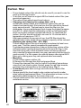
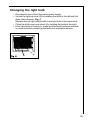
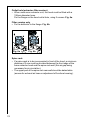
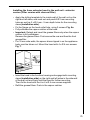
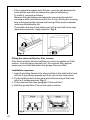
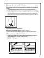
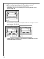
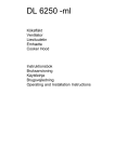
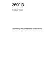
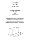
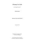
DF 6260
Köksfläkt
Ventilator
Liesituuletin
Emhætte
Cooker Hood
Instruktionsbok
Bruksanvisning
Käyttöohje
Brugsvejledning
Operating and Installation Instructions
Contents
Safety instructions ............................................................................
Description of the cooker hood ..........................................................
Using the cooker hood ......................................................................
Maintenance and cleaning .................................................................
If the cooker hood will not operate .....................................................
Guarantee conditions ........................................................................
Technical data ...................................................................................
Special accessories ..........................................................................
Installation ........................................................................................
63
65
66
67
70
70
71
72
72
Safety instructions
This appliance is to be used solely as a household appliance. It has
been manufactured according to the international safety and quality
standards. Note that the safety devices alone are not capable of
eliminating all accident risks. It is therefore very important to carefully
read all the operating instructions, recommendations and warnings prior
to installation and use of the appliance. Note in particular the text
paragraphs with the danger triangle design, to avoid damages to
persons or objects. Keep this instruction booklet in a safe place: this
booklet should always accompany the appliance at such time as it is
sold or given to other persons for use.
Installation and service
• Any electrical installation of the cooker hood must be carried out by
a qualified electrician and the hood itself must be installed by
someone with experience. Installation made by an unqualified
person can lead to loss of function of the cooker hood and possible
damage to person and and/or property.
• The cooker hood must be at least 47 cm above electric hobs or
electric ranges, or at least 65 cm above gas burners or gas ranges.
• Ensure that the power cable is not damaged during installation.
• The cooker hood is only in stand by mode unless the plug or the
fuse is disconnected.
• The cooker hood cannot be connected to flues of other appliances
that run on energy sources other than electricity. Please, keep to the
provisions of official directives regarding fume discharge.
63
Use of cooker hood
• This appliance is for domestic use only in a normal household.
• Never leave any deep-frying, melting fat, paraffin or any other
inflammable liquid unattended on the hob. In the event of fire:
Immediately switch off the cooker hood and the cooker. Note! Cover
the fire. Never use water.
• Never do any flambé cooking underneath the cooker hood. It can
cause a fire. Remember that overheated fat may spontaneously
ignite. Never leave the frying pan unattended.
• It is essential that the grease filter is regularly cleaned to help avoid
fat dripping on to the hot zone and causing a fire. Read the section
on “Maintenance and Cleaning” in the instruction book.
Disposal
• Prevent accidents when disposing of your cooker hood. Disconnect
the power plug from the wall socket and cut the power cord at the
hood inlet.Contact your local authority for information on where to
dispose the cooker hood.
64
Description of the cooker hood
Functions
There are two possible systems:
• Extraction of air to the outside using an optional venting kit and
evacuation duct.
• Recirculation using an optional
charcoal filter.
The air outlet must not be connected to chimney flues or
combustion gas ducts. The air outlet must under no circumstances
be connected to ventilation ducts for rooms in which fuel-burning
appliances are installed.
Fig. 1
A = Switches (Motor, light)
B = Grease filter
C = Light
D = Control panel
E = Vapour catcher (Extractible)
Accessories
The following are included with the cooker hood.
• 1 hood canopy complete with controls, lighting and fan motor.
• 1 Adaptor Ø 150 mm.
• 1 plastic bag containing: documentation, screws to fix the hood.
The following can be ordered from your retailer:
• Charcoal filter, KFL 60/80 (should be replaced every year).
or
• Charcoal filter, KF8 (typ 150 – can be regenerated and should be
replaced every 3 years).
The carbon filter is to be used when the hood is connected to the
recirculation mode.
65
Using the cooker hood
The control panel
• The switches are arranged on
the upper right side of the
vapour catcher. (Fig. 1 - E).
The numbers and symbols
have the following meanings
(from left to right):
The blower is controlled by
shifting the sliding switch.
The extractor part (vapour
catcher) of the hood is used to
switch the blower on and off
when the appliance is switched
on (Motor).
= Continuously variable
blower control
= Intensive setting
= Lighting
= Lighting OFF
= Lighting ON
When the vapour catcher of the appliance is withdrawn (without
preceding disengagement of the hood via the switches), the set fan
output is automatically re-engaged.
If the extractor part is re-inserted without operation of the switches, first
the blower is switched off.
The lighting can be separately switched on and off with the sliding
switch.
Best results are obtained by using a low speed for normal conditions
and high speed when odours are more concentrated. Turn the hood on
a few minutes before you start cooking then you will get an
underpressure in the kitchen. It should be left on after cooking for about
15 minutes or until all odours have disappeared.
Correct ventilation
If the cooker hood is to work correctly there must be an underpressure
in the kitchen. It is important to keep the kitchen windows closed and
have a window in an adjacent room open.
Important to know
Not applicable for recirculation. Great care must be taken if the hood is
used at the same time as a burner or fireplace (e.g. gas, diesel, coal or
wood heaters, water heaters, etc.), as the hood will expel air which is
required by these other appliances. Attend to it by opening a window.
The negative pressure in the room must not exceed 0,04 mbar to
prevent fumes being drawn back into the room by the cooker hood.
66
Maintenance and cleaning
Disconnect the cooker hood from the power supply prior to
cleaning the appliance, either by removing the plug from the mains
or removing the fuse.
Clean the filter regularly. The grease deposits in the filter and
discharge tube are fire hazards where a hotplate (or another heat
source) is left on by error.
Cleaning the hood
Clean the outside of the hood using a damp cloth and a mild detergent.
Never use corrosive, abrasive or flammable cleaning products.
Cleaning the grease filters
Clean the filter every month or every other
month according to how much the hood is
used. The cleaner the filters, the more
grease they collect. To remove the filters
(Fig. 4):
• Pull the lock outwards and extract the
grease filter. Fig. 4.
The filter is made of aluminium wires on
which the grease collects. Clean the filter
in hot water using a detergent, or in a
dishwasher. Let the filter dry before putting
it back. Note that a dishwasher may
discolour the filter.
Fig. 2
67
Carbon filter
• The activated carbon filter should only be used if you want to use the
hood in its filtering function.
• To do this you will need an original AEG activated carbon filter (see
special accessories).
• The carbon filters absorb smells and odours.
• Changing and cleaning the carbon filter - KF 8
Unlike other carbon filters, the LONGLIFE carbon filter can be
cleaned and reactivated. At normal use the filter should be cleaned
every second month. The best way to clean the filter is in the
dishwasher. Use normal detergent and choose the highest temperature (65º C). Wash the filter separately so that no food parts gets
stuck on the filter and later causes bad odours. To reactivate the
carbon, the filter should be dried in an oven for 10 minutes with a
temperature of maximum 100º C.
After approximately three years of use, the KF8 filter should be
replaced with a new, as the odour reduction capacity will be reduced.
• Replacing the carbon filter - KFL 6080
The activated carbon filter must normally be replaced at least once
every year. This filter cannot be washed or regenerated.
To guarantee proper absorption of odours the working volume of the
activated carbon must be proportionate to the hood air flow. In this
case the high quality of the activated carbon will ensure efficient
odour removal for approximately one year, assuming that the hood is
used normally. For this reason you should always use original AEG
filters only, making sure they are replaced when necessary.
• Mounting
1. Pull out the vapour catcher (A).
2. Remove first the rear then the front grease filters.
3. Insert the charcoal filter into the lugs of the holding frame above
using the 2 red clips to retain it below, press the red clips inwards,
and insert the charcoal filter in the holding frame. Fig. 3.
• To dismount press both red lugs and remove the carbon filter
downwards.
• Always specify the hood model code number and serial number
when ordering replacement filters. This information is shown on the
registration plate located on the inside of the unit.
• The activated carbon filter can be ordered from the AEG technical
assistance service.
Fig. 3
68
Changing the light bulb
• Disconnect the unit from the mains power supply.
• Unlock the lighting cover (D) by twisting the bolts to the left and fold
down the bulb cover. Fig. 4.
Replace the old light bulb(s) with a new light bulb of the same kind.
• Close the bulb cover and relock it by twisting the bolts to the right.
• If the light does not come on, make sure the bulb has been inserted
in correctly before contacting the technical assistance service.
Fig. 4
D
69
If the cooker hood will not operate
Check the following prior to calling after sales
service:
• Has a fuse burnt? Check both fuses and replace if necessary.
• Is the power supply plug inserted properly in the power outlet?
• Has the flexible tube been mounted correctly?
• Is the anti-grease filter clean?
• Are the light bulbs intact and soundly fitted?
If the problem persists, contact the sales center, the after sales service
center or an authorized technician. Only use original spare parts.
Under no circumstances carry out modifications to the cooker hood
which may cause harm to persons and/or damage objects.
After sales service and spare parts
It is important to always indicate the appliance product number and
model type when requesting after sales service or ordering spare parts.
This information is indicated on the motor casing label.
Guarantee conditions
Guarantee Conditions
AEG offer the following guarantee to the first purchaser of this appliance.
1. The guarantee is valid for 12 months commencing when the appliance
is handed over to the first retail purchaser, which must be verified by
purchase invoice or similar documentation.The guarantee does not
cover commercial use.
2. The guarantee covers all parts or components which fail due to faulty
workmanship or faulty materials. The guarantee does not cover
appliances where defects or poor performance are due to misuse,
accidental damage, neglect, faulty installation, unauthorised
modification or attempted repair, commercial use or failure to observe
requirements and recommendations set out in the instruction book.This
guarantee does not cover such parts as light bulbs, removable glassware or plastic.
3. Should guarantee repairs be necessary the purchaser must inform the
nearest customer service office (manufacturer`s service or authorised
agent). AEG reserves the right to stipulate the place of the repair
(i.e.the customer`s home, place of installation or AEG workshop).
4. The guarantee or free replacement includes both labour and materials.
5. Repairs carried out under guarantee do not extend the guarantee
period for the appliance. Parts removed during guarantee repairs
become the property of AEG.
6. The purchaser`s statutory rights are not affected by this guarantee.
70
European Guarantee
If you should move to another country within Europe then your
guarantee moves with you to your new home subject to the following
qualifications:
The guarantee starts from the date you first purchased your product.
The guarantee is for the same period and to the same extent for labour
and parts as exists in the new country of use for this brand or range of
products.
This guarantee relates to you and cannot be transferred to another user.
Your new home is within the European Community (EC) or European
Free Trade Area.
The product is installed and used in accordance with our instructions
and is only used domestically, i.e. a normal household.
The product is installed taking into account regulations in your new
country.
Before you move please contact your nearest Customer Care centre,
listed below, to give them details of your new home. They will then
ensure that the local Service Organisation is aware of your move and
able to look after you and your appliances.
France Senlis
+33 (0)3 44 62 20 13
Germany N.rnberg
+49 (0)800 234 7378
ItalyPordenone
+39 (0) 800 117511
Sweden Stockholm
+46 (0)20 78 77 50
UKSlough
+44 (0) 1753 219898
Technical data
Size
Light
Grease filter
Voltage
Total power
Height
Width
Depth
38,7 cm
59,9 cm
27,5 cm
Max 2x9 W
2 st.
220-240 V
250 W
71
Special accessories
Charcoal KLF 60/80
Charcoal KF 8
E-Nr. 610 899 421
942 120 399
Installation
Unpacking
Check that the cooker hood is not damaged. Transportation damages
should immediately be reported to the transport company. Damages,
faults and missing parts should immediately be reported to the retailer.
Dispose carefully of the packaging material so that it is out of the way
of small children.
Position
The cooker hood should be mounted freely hanging on the wall. The
cooker hood must be at least 47 cm above electric hobs or electric
ranges, or at least 65 cm above gas burners or gas ranges.
The cooker hood cannot be connected to flues of other
appliances that run on energy sources other than electricity.
Please, keep to the provisions of official directives regarding fume
discharge.
Electrical connection
The hood has a power cable with earth connection and the rated voltage
is 220 - 240 V.
72
Installation
Preparing the wall unit - Extractor version
• The hood is supplied as an extractor unit.
Before installing the hood, drill a hole in the roof of the wall unit
(see Fig. 5). This hole is to allow passage of the outlet pipe and the
power cable, and to facilitate servicing.
190
172
238
Fig. 5
• The wall unit must have a minimum body depth (without door) of 300
mm with recessed light screen and min. 370 mm with flush-mounted
light screen. The unobstructed internal height must be at least 370
mm.
73
Outlet hole (extractor-filter version)
• When used as an extractor unit, the hood must be fitted with a
150mm diameter hose.
Fix the flange on the hood outlet hole, using 2 screws. Fig. 6a.
Filter version only
• Fix the deflector to the flange. Fig. 6b.
Fig. 6a
Fig. 6b
Spice rack
• If a spice rack is to be incorporated in front of the hood, a minimum
distance of 5 mm must be provided between the front edge of the
fume extractor hood and the spice rack wall (this air gap being
necessary for air circulation).
• The upper part of the spice rack rear wall should be detachable
(access for exhaust air hose or adjustment of furniture housing).
74
Installing the fume extractor hood in the wall unit - extractor
version (Filter version with charcoal filter)
• Apply the drilling template to the inside wall of the wall unit on the
right and left sides, and mark out and predrill Ø 2 mm mounting
holes as well as 2 x Ø 6 mm - 5 mm depth holes for the mounting
claws (installation aids).
• Fix the flange on the hood outlet hole, using 2 screws. Fig. 6a.
• Fully withdraw the vapour catcher of the hood.
• Important: Detach and insert the grease filters only when the vapour
catcher is fully withdrawn.
Remove the grease filters. First remove the rear and then the front
grease filter.
• For 19 mm side walls, the spacer discs clipped in on the appliance
body must be taken out. Mount the hood with 4 x Ø 4 mm screws.
Fig. 7.
Fig. 7
• Insert the hood in the furniture housing and engage both mounting
claws (installation aids) on the right and left sides in the side wall
of the wall unit and firmly hold the hood for further mounting.
Then fix the hood with the 4 or 6 x Ø 4 mm screws supplied.
• Refit the grease filters. Push-in the vapour catcher.
75
• If the cupboard is deeper than 300 mm, cover the gap between the
hood and the wall with a finishing strip (special accessory).
To install it, proceed as follows:
Measure the wall distance and apply the covenng strip over the
necessary width (wall distance plus 5 to 8 mm), kinking the covering
strip at the appropriate notches and tearing off the surplus material
(removing the protective foil).
Then fasten the strip to the bottom part of the hood with three clips
(special accessories). Apply pressure. Fig. 8.
Fig. 8
Fitting the charcoal filter for filter version
If the fume extractor hood is installed as a return air appliance (Filter
version - air outlet above the wall unit), the charcoal filter (special
accessory) must be fitted before the grease filters are fitted.
Installation sequence:
1. Insert the holding frame for the charcoal filter in the shaft of the hood
with the 2 lugs facing upwards and then clip into the lower holes.
2. Fix the holding frame on the lower part of the housing of the hood
with the 2 screws supplied. Fig. 9.
3. Fit the charcoal filter (see paragraph “Charcoal filter”)
4. Refit the grease filters. Push-in the vapour catcher.
Fig. 9
76
Removing the hood from the wall unit
If, for technical reasons (extractor version/filter version conversion) the
fume extractor hood has to be removed from the wall unit, proceed as
follows:
• Fully withdraw the vapour catcher and remove the grease filter.
• Loosen the 4 or 6 mounting screws of the hood (wall unit mounting).
• To loosen both mounting claws (installation aids), place a max 3 mm
dia. Phillips screw-driver in the spring opening and simultaneously
press the springs inwards (towards the appliance housing). Fig. 10.
Fig. 10
Important: Hold the hood firmly!
Adjusting the extractor part (E - Fig. 1) - Fig. 11
On wall units with a body depth of 275 mm to 335 mm, the vapour
catcher depth can be adjusted as follows:
• Remove both grease filters.
• Loosen the screws on both end-stop brackets and set the vapour
catcher depth (min. 275 mm, max. 335 mm).
• Refit the screws.
• Refit the grease filters.
Fig. 11
77
Installing the front panel (see also “Special accessories”)
• Remove first the rear then the front grease filters.
• Remove the internal cover pressing both unlocking devices (press
and pull). Fig. 12.
Fig. 12
• Predrill the front panel as per template and fix it to the vapour catcher
with 3 screws. Fig. 13-14.
Fig. 13
Fig. 14
• Clip the Internal cover back in and insert both grease filters (first the
front one and then the rear one).
78
79
AEG Hausgeräte GmbH
Postfach 1036
D-90327 Nürnberg
http://www.aeg.hausgeraete.de
© Copyright by AEG
LI1YSA Ed. 05/02