1
VSP-V-9939A
Issue 8
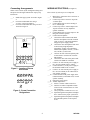
V-9939A
MICROPHONE ADAPTOR
INTRODUCTION
These instructions provide identification, installation,
connection, operation, and maintenance information
for the V-9939A, Microphone Adaptor.
The V-9939A is a Microphone Adaptor designed to
be used with Valcom paging equipment.
SPECIFICATIONS
Purpose
•
Provides microphone access to Valcom one-way
amplified speaker assemblies.
Power Requirements
Applications
•
•
–21.5 to –26 Vdc filtered "A" Battery, 40 ma. max
Allows local paging access to a zone of one-way
paging speakers.
Allows paging access to stand alone systems.
Environment
Temperature:
Humidity:
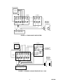
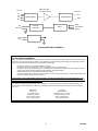
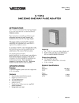
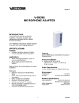
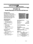
Refer to Figure 1 for a block diagram of a typical
installation.
0 to 50 Degrees C
0 to 85% non-precipitating
Nominal Specifications
Input impedance
Features
•
•
•
•
•
•
•
Output impedance
Output level
600 ohms balanced and 50,000 ohm inputs
Works with most microphones with push to talk
switches
Built in microphone preamplifier
Mounts at microphone location
Provides a set of form "C" contacts
May be connected to a selected zone of a multizone paging system
Screw terminals for all connections
SYSTEM DESIGN
Configuration
There are two basic ways the V-9939A Microphone
adaptor may be used:
1.
Capacity
Each V-9939A may be connected to one zone of a
paging system.
It may be used with a V-1094A and Valcom
one-way amplified speaker assemblies as a
stand alone paging system.
When using the V-9939A for access to a stand alone
paging system, the following will be required:
Dimensions/Weight
•
600 ohms balanced/
50,000 ohms unbalanced
600 ohms
-10dbm nominal
•
•
•
7.1”H x 4.7”W x 2.1"D
(18.03 cm H x 11.94 cm W x 5.33 cm D)
0.7lbs. (32kg)
1
1 V-9939A Microphone Adaptor
1-Microphone (push to talk)
1 V-1094A Booster Control
947939A
•
•
2.
Microphone Requirements
Valcom one-way amplified speaker assemblies
(type determined by job requirements)
Power Supply (type determined by style and
quantity of speakers - Consult the Valcom
One-Way Paging VSP for more information)
A standard high impedance (50,000 ohms) or low
impedance balanced (600 ohms) microphone may be
used. The microphone will be required to provide a
dry contact closure (push to talk) for page access.
By using the V-9939A with a V-1101A One
Zone One-way Page Adaptor or a V-9937
One Zone Page Port Adaptor you may
automatically disconnect the speakers of one
zone from a multi-zone page adaptor and
allow microphone access to that zone.
These configurations will allow the
microphone to override the telephone
access.
NOTE: These will work only on a zone of
ONE-WAY paging.
Amplified Speakers
V-9939A
V-1094A
INSTALLATION
These instructions cover the installation procedures
for the Valcom V-9939A and any associated Valcom
equipment. Please consult practices for other
manufacturer's equipment if any other equipment is
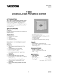
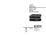
being used. Refer to Figure 2 for location of screw
connections. Refer to Figure 3 for screw connection
designations.
The following sections contain step-by-step
instructions for wiring the V-9939A and associated
Valcom equipment. Each instruction is preceded by a
line. Place a check on the appropriate line as the
instruction is completed. The instructions also
include tests along the way to verify connections have
been made correctly. If these steps are followed
exactly, installation of your Valcom system will go
smoothly and quickly. If the results of a test do not
correspond with what is shown, DO NOT PROCEED
UNTIL THE PROBLEM HAS BEEN
CORRECTED.
NOTE: During initial system setup it is
recommended that all volume controls be set 1/2 turn
clockwise.
Power
Supply
Mounting
•
Figure 1 - Block Diagram of a Typical Installation
When using the V-9939A to override an existing zone
of telephone accessed one-way paging, the following
will be required:
•
•
•
•
•
1 V-9939A Microphone Adaptor
1-Microphone (push to talk)
1 V-1101A One Zone Page Adaptor
OR
1 V-9937 One Zone Page Port Adaptor
An existing Valcom one-way page system
Using two #6 3/4" wood screws, mount the unit
in a convenient location near the microphone
location
NOTE: DO NOT locate the V-9939A closer than
18" to a power supply or any equipment that
generates electrical noise.
Power Connections
___ 1.
___ 2.
Other configurations are possible. Contact Technical
Support {(540) 427-3900} with questions on specific
applications.
___3.
2
Unplug power supply.
Connect –24 Vdc "A" battery (may be
referred to as "-" or "talk battery") from
power supply to one of the PWR terminals
on the V-9939A.
Connect –24 Vdc Ground ("A" ground,
"+" or "talk" ground) from power supply to
the other power terminal. This GND should
be properly grounded to an earth ground to
alleviate hum on the system.
947939A
Connecting Arrangements
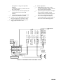
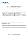
WIRING INSTRUCTIONS (For Figure 4)
NOTE: Place a check by the Arrangement being used
and proceed to the Figure indicated for step-by-step
instructions.
Place a check by each step as it is completed:
___1.
___1.
___2.
___3.
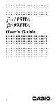
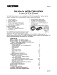
Stand alone page system: Proceed to Figure
4.
Override an individual zone using a
V-1101A: Proceed to Figure 5.
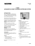
Override an individual zone using a V-9937:
Proceed to Figure 6.
Volume
Control
V-9939A
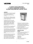
Figure 2 - Location of Screw
and Volume
PWR MC HZ B
S
RING
PWR LZ1SW GND M TIP
OUT
LZ2
Figure 3 - Screw Connection
Designations
3
Mount the V-1094A near the V-9939A or at
the main frame.
___2. Connect Tip of the V-9939A to Tip of the
V-1094A input.
___3. Connect Ring of the V-9939A to Ring of
the V-1094A input.
___4. Connect Tip of the V-1094A output to the
Tip side of all the one-way amplified
speaker assemblies.
___5. Connect Ring of the V-1094A output to the
Ring side of all the speakers.
___6. Connect the microphone:
___a. Connect the audio common lead shield
from the microphone to the MC terminal
of the V-9939A. (This shield should be
strapped to power supply GND).
___b. Connect the other microphone audio lead
to HZ if using a high impedance
microphone; if using a low impedance
balanced microphone, connect (+) lead to
LZ1, and the (-) lead to LZ2.
___c. Connect one side of the microphone push
to talk switch to switch to the V-9939A
SW terminal.
___d. Connect the other side of the push to talk
switch to the GND OUT terminal.
___7. Connect –24 Vdc from the power supply to
the –24 Vdc terminal of the V-1094A.
___8. Connect Ground (+) of the power supply to
the Ground terminal of the V-1094A.
___9. Connect –24 Vdc from the power supply to
the –24 Vdc terminal (or the white lead) of
each speaker assembly.
___10. Connect Ground of the power supply to the
Ground terminal (or the black lead) of each
speaker assembly.
___11. Plug in the power supply.
___12. Volume adjustment:
___ a. Set the V-1094A volume control to 5.
___ b. Turn the screwdriver adjustable volume
control on the V-9939A about 1/2 of the
way clockwise.
___ c. Verify all speaker controls are set at 1/2.
___ d. Speak through the microphone and adjust
the V-1094A for the proper system level.
___ e. Speak through the microphone and adjust
the individual speakers to the required
levels.
947939A
MICROPHONE
SWITCH
AUDIO
GND STRAP
PWR MC
HZ
PWR LZ1 SW
B
S
GND M
OUT
V-9939A
V-1094A
RING
R IN -24 R OUT
T IN GND T OUT
TIP
ONE-WAY
AMPLIFIED
SPEAKER
ASSEMBLIES
LZ2
AB AG BB BG
-24VDC POWER SUPPLY
FIGURE 4 - STAND ALONE PAGE SYSTEM
V-1101A
MICROPHONE
WH/BL
BL/WH
WH/OR
WH/GN
SWITCH
AUDIO
RD/GN
GN/RD
RD/BN
BN/RD
GND STRAP
V-9939A
PWR MC
B
HZ
PWR LZ1 SW
S
GND M
OUT
TO ONE ZONE
OF A PAGE
CONTROL UNIT
VI/BN
BN/VI
VI/SL
SL/VI
RING
ONE-WAY
AMPLIFIED
SPEAKER
ASSEMBLIES
TIP
LZ2
AB AG BB BG
-24VDC POWER SUPPLY
FIGURE 5 - OVERRIDE A SINGLE ZONE WITH A V-1101A
4
947939A
WIRING INSTRUCTIONS (For Figure 5)
Place a check by each step as it is completed:
___ 1.
___ 2.
___ 3.
___ 4.
___ 5.
___ 6.
___ 7.
___ 8.
___ 9.
___10.
___11.
___12.
___a.
___b.
___c.
___d.
___13.
___14.
___15.
IMPORTANT: Complete installation and
testing of your page control unit and
speakers before adding the microphone
adaptor.
Mount the V-1101A near the microphone
adaptor and connect it to a terminated 25
pair cable.
Connect Tip of the V-9939A to Tip
(white/blue) of the V-1101A.
Connect Ring of the V-9939A to Ring
(blue/white) of the V-1101A.
Add a jumper on the V-1101A between the
white/orange and the white/green.
Connect the white/orange of the V-1101A to
terminal S on the microphone adaptor.
Connect the violet/slate of the V-1101A to
terminal M of the microphone adaptor.
Disconnect Tip of the audio pair to the
speakers on the zone being overridden from
the Page Control unit and connect it to the
red/brown of the V-1101A.
Disconnect Ring of the audio pair to the
speakers from the Page Control unit and
connect it to the brown/red of the V-1101A.
Connect the red/green of the V-1101A to
one side of the output pair from the page
control unit for the zone to be overridden.
Connect the green/red of the V-1101A to the
other side of the output pair from the page
unit for the zone being used.
Connect the microphone:
Connect the audio common lead shield of
the microphone to the MC terminal of the
V-9939A. This shield should be strapped
to power supply GND.
Connect the other microphone audio lead
to HZ if using high impedance
microphone; if using a low impedance
balanced microphone, connect (+) lead to
LZ1 and the (-) lead to LZ2.
Connect one side of the microphone push
to talk switch to the V-9939A SW
terminal.
Connect the other side of the push to talk
switch to the GND OUT terminal.
Connect –24 Vdc filtered talk battery from
the power supply to the brown/violet of the
V-1101A.
Connect Ground (+) of the power supply to
the violet/brown of the V-1101A.
Connect –24 Vdc signal battery from the
power supply to the slate/violet of the
V-1101A.
5
___16. Connect signal ground of the power supply
to the violet/slate of the V-1101A.
___17. Power Test
___a. Plug in the power supply.
___b. Momentarily short between the white/slate
and slate/white of the V-1101A. If you
hear a relay activate, then go to step 18.
___c. If you do not hear a relay, then unplug the
power supply and go back to steps 13 to
16 and verify your connections.
___18. Volume adjustment:
___a. Turn the screwdriver adjustable volume
control on the V-9939A about 1/2 of the
way clockwise.
___b. Speak through the microphone and adjust
the V-9939A screwdriver adjustment for
the proper page level.
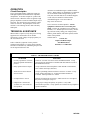
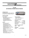
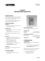
WIRING INSTRUCTIONS (For Figure 6)
Place a check by each step as it is completed:
___ 1.
___ 2.
___ 3.
___ 4.
___ 5.
___ 6.
___ 7.
___ 8.
___ 9.
___10.
___11.
___a.
___b.
IMPORTANT: Complete installation and
testing of your page control unit and
speakers before adding the microphone
adaptor.
Mount the V-9937 near the microphone
adaptor.
Connect Tip of the V-9939A to pin 2 of the
V-9937.
Connect Ring of the V-9939A to pin 17 of
the V-9937.
Connect terminal S of the V-9939A to pin 3
of the V-9937.
Connect terminal M of the V-9939A to pin
18 of the V-9937.
Disconnect Tip of the audio pair to the
speakers on the zone being overridden from
the Page Control unit and connect it to pin 7
of the V-9937.
Disconnect Ring of the audio pair to the
speakers from the Page Control Unit and
connect it to pin 22 of the V-9937.
Connect pin 4 of the V-9937 to one side of
the output pair from the page control unit
for the zone being overridden.
Connect pin 19 of the V-9937 to the other
side of the output pair from the page control
unit for the zone being overridden.
Connect the microphone:
Connect the audio common lead shield of
the microphone to the MC terminal of the
V-9939A. This shield should be strapped
to power supply GND.
Connect the other microphone audio lead
to HZ if using a high impedance
947939A
TIP INPUT 1
TO A ZONE OF A
PAGE CONTROL
UNIT
TIP INPUT 2
TIP INPUT 3
CONTROL GND IN
-24 OUT
-24 OUT
TIP OUT 1
TIP OUT 2
-24 OUT
___13.
WARBLE TONE
___12.
SINGLE TONE
___d.
GND OUT
___c.
___14. Volume adjustment:
___a. During initial system set up, set the
screwdriver adjustable volume control on
the V-9939A 1/2 turn clockwise.
___b. Speak through the microphone and adjust
the screwdriver adjustable volume
controls on the V-9939A and output 1 of
the V-9937 to the desired page level.
___c. Access zone through the telephone
system; adjust input 3 volume control on
the V-9937 for the desired page level.
microphone: if using a low impedance
balanced
microphone, connect (+) lead to LZ1 and
the (-) lead to LZ2.
Connect one side of the microphone push
to talk switch to the V-9939A SW
terminal.
Connect the other side of the push to talk
switch to the GND OUT terminal.
Connect –24 Vdc (BB) signal battery from
the power supply to pin 30 of the V-9937.
Connect signal ground (BG) of the power
supply to pin 29 of the V-9937.
15 14 13 12 11 10 9 8 7 6 5 4 3 2 1
30 29 28 27 26 25 24 23 22 21 20 19 18 17 16
RING INPUT 2
RING INPUT 1
CONTROL GND OUT
RING INPUT 3
RING OUT 1
PWR LZ1 SW GND M
OUT
GROUND OUT
S
GROUND OUT
B
RING OUT 2
PWR MC HZ
V-9939A
WARBLE TONE
GND STRAP
SINGLE TONE
SWITCH
AUDIO
GROUND IN
-24VDC IN
MICROPHONE
RING
ONE-WAY
AMPLIFIED
SPEAKER
ASSEMBLIES
TIP
LZ2
AB AG BB BG
-24VDC POWER SUPPLY
FIGURE 6 - OVERRIDE A SINGLE ZONE WITH A V-9937
6
947939A
OPERATION
Assistance in troubleshooting is available from the
factory. When calling, you should have a VOM and a
test set available and be calling from the job site.
Call (540) 427-3900 and ask for Technical Support,
or call (540) 427-6000 for Valcom 24-hour
Automated Support or visit our website at
http://www.valcom.com.
Circuit Description
The V-9939A Microphone Adaptor has inputs for
both high impedance and balanced low impedance
microphones. It also has an input for a push to talk
contact closure. When the closure is applied, a high
gain pre-amplifier is turned on and the output relay is
activated. The unit will stay active until the contact
closure is removed. The preamplifier circuit also
contains a voice limiting circuit to limit extremely
loud inputs.
TECHNICAL ASSISTANCE
When trouble is reported, verify that power is being
supplied to the unit and there are no broken
connections. Check voltages for proper polarity on
the crossconnect block.
Table 1 identifies symptoms of some possible
problems with solutions. If a spare unit is available,
continue to troubleshoot by substituting the spare unit
for the suspected defective unit.
The V-9939A is not field repairable. Valcom
equipment contains no user serviceable parts
inside. Valcom, Inc. maintains service facilities in
Roanoke, VA. Should repairs be necessary, attach a
tag to the unit clearly stating your company name,
address, phone number, and contact person; and the
nature of the problem.
Send the unit to:
Valcom, Inc.
Repair and Return Dept.
5614 Hollins Road
Roanoke, VA 24019-5056
TABLE 1 - TROUBLESHOOTING CHART
SYMPTOM
1. No relay operation in V-9939A
when microphone talk button is
pressed.
SOLUTION
Check for –24 VDC at V-9939A across the PWR terminals. Verify
connection from microphone to terminals SW and GND OUT (refer to
the Installation section).
2. Relay operation but no output.
Verify connections from microphone to MC and HZ or LZ terminals.
Turn volume control up (clockwise).
3. Audio from V-9939A but not
from V-1094A.
Verify Tip and Ring connections from V-9939A to V-1094A. Verify
proper voltage and polarity at –24 VDC and GND terminals of
V-1094A. Turn up volume at V-1094A.
4. No output from V-1101A.
Recheck all connections per Figure 5. Make sure the V-1101A passes
the power test in Figure 5, step 17.
5. Output from V-9939A and
V-1094A or V-1101A but not
from speakers.
Verify proper voltage and polarity to speakers. Verify audio
connections to speakers. Verify speakers are Valcom one-way amplified
speaker assemblies.
7
947939A
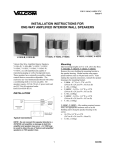
AMPLIFIER AND
VOLUME CONTROL
INPUTS
HZ
LZ1
LZ2
MC
SW
GND OUT
OUTPUTS
TIP
TRANSFORMER
TRANSFORMER
RING
CONTROL
CIRCUITRY
RELAY
MAKE
STATIONARY
BREAK
PWR
PWR
V-9939A SIMPLIFIED SCHEMATIC
VALCOM LIMITED WARRANTY
Valcom, Inc. warrants its products to be free from defects in materials and workmanship under conditions of normal use and service
for a period of one year from the date of shipment. The obligation under this warranty shall be limited to the replacement, repair or
refund of any such defective device within the warranty period, provided that:
1.
2.
3.
4.
5.
inspection by Valcom, Inc. indicates the validity of the claim,
the defect is not the result of damage, misuse, or negligence after the original shipment.
the product has not been altered in any way or repaired by others and that factory sealed units are unopened (A service
charge plus parts and labor will be applied to units defaced or physically damaged),
freight charges for the return of products to Valcom are prepaid,
all units ‘out of warranty’ are subject to a service charge. The service charge will cover minor repairs (Major repairs will be
subject to additional charges for parts and labor).
This warranty is in lieu of and excludes all other warranties, expressed or implied, and in no event shall Valcom, Inc. be
liable for any anticipated profits, consequential damages, loss of time or other losses incurred by the buyer in connection
with the purchase, operation, or use of the product.
This warranty specifically excludes damage incurred in shipment. In the event a product is received in damaged condition, the
carrier should be notified immediately. Claims for such damage should be filed with the carrier involved in accordance with the
F.O.B. point.
Headquarters:
Valcom, Inc.
1111 Industry Avenue
Roanoke, VA 24013
Phone: (540) 427-3900
FAX: (540) 427-3517
In Canada
CMX Corporation
35 Van Kirk Drive #11 and 12
Brampton, Ontario L7A1A5
Phone: (905) 456-1072
FAX: (905) 456-2269
8
947939A