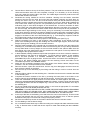
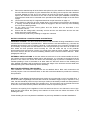
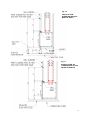
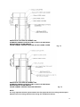
1
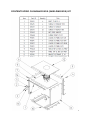
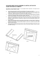
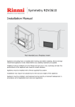
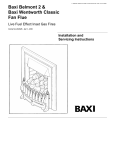
SPECIFICATION & INSTALLATION GUIDE FOR
MASPORT LE4000 PROVINCIAL BUILT-IN FIRE,
NEW ZEALAND MODEL
Manufactured in New Zealand by:
GLEN DIMPLEX AUSTRALASIA LIMITED
P.O. Box 58 473, Botany
Auckland 2163
Ph: 0800 666 2824
Fax: 09 274 8472
Email: [email protected]
Web: www.glendimplex.co.nz
20.03.2012
Part. No. 593398
1
CONTENTS ZERO CLEARANCE BOX (SHIELDING BOX) KIT
2
DIMENSIONS:
Fig. 1
MODEL
D
F
FF
FH
FW
H
W
LE4000 PROV
BUILT-IN
525
210
315
750
965
696
715
INTRODUCTION
In the interest of your safety, building regulatory Authorities in Australia and New Zealand require
any woodfire installation to comply with Installation Standard AS/NZS 2918:2001. They may also
have local requirements in addition to those in the Standard. Check with your local Building
Authority before commencing installation to find if you will require a Building Consent and
whether there are extra requirements. This woodfire has been tested to ensure that it will meet
the appropriate safety Standard requirements when these instructions are followed. As the safety
and emission performance can be affected by altering the appliance, no modifications are
allowed without written permission from the manufacturer.
The model LE4000 Provincial has been tested to demonstrate compliance with current general
emission requirements in New Zealand, but some areas have stricter limits. So check the
requirements for your area before purchase or installing the unit.
3
WE RECOMMEND THAT THE INSTALLATION OF YOUR MASPORT SOLID FUEL BURNING
APPLIANCE BE CARRIED OUT BY A QUALIFIED INSTALLATION TECHNICIAN.
LE4000 PROVINCIAL MODEL HAS AIR RECIRCULATING FAN WHICH MUST BE INSTALLED
AND ALL ELECTRICAL WORK BE CARRIED OUT BY A LICENSED ELECTRICIAN. REFER
DETAILED INSTRUCTIONS FOR INSTALLATION OF FAN FOR THIS MODEL ON PAGE 14.
IN SOME REGIONS POWER POINTS ARE NOT PERMISSIBLE WITHIN THE FLOOR
PROTECTOR AREA, PLEASE CHECK WITH YOUR LOCAL AUTHORITY.
IF THE SUPPLY CORD IS DAMAGED, IT MUST BE REPLACED BY THE MANUFACTURER OR
ITS SERVICE AGENT OR A SIMILARY QUALIFIED PERSON IN ORDER TO AVOID
ELECTRICAL HAZARD.
WARNING: THE APPLIANCE AND FLUE SYSTEM MUST BE INSTALLED IN ACCORDANCE
WITH AS/NZS 2918:2001 AND THE APPROPRIATE REQUIREMENTS OF THE REVELANT
BUILDING CODE OR CODES.
WARNING: APPLIANCES INSTALLED IN ACCORDANCE WITH THIS STANDARD MUST
COMPLY WITH THE REQUIREMENTS OF AS/NZS 4013 WHERE REQUIRED BY THE
REGULATORY AUTHORITY, I.E. THE APPLIANCE SHALL BE IDENTIFIABLE BY A
COMPLIANCE PLATE WITH THE MARKING ‘TESTED TO AS/NZS 4013’. ANY MODIFICATION
OF THE APPLIANCE THAT HAS NOT BEEN APPROVED IN WRITING BY THE TESTING
AUTHORITY IS CONSIDERED TO BE IN BREACH OF THE APPROVAL GRANTED FOR
COMPLIANCE WITH AS/NZS 4013.
LE4000 PROVINCIAL APPLIANCES CAN NOT BE FITTED WITH WATER HEATING DEVICE
SUCH AS WATER BOOSTER.
CAUTION :
•
PLEASE ENSURE THAT ONLY COMPONENTS APPROVED BY GLEN DIMPLEX
AUSTRALASIA LTD ARE USED FOR INSTALLATION, as substitutes may adversely affect
performance and might nullify compliance with the requirements of AS/NZS 2918:2001.
•
MIXING OF APPLIANCE OR FLUE SYSTEM COMPONENTS FROM DIFFERENT
SOURCES OR MODIFYING THE DIMENSIONAL SPECIFICATION OF COMPONENTS
MAY RESULT IN HAZARDOUS CONDITIONS. WHERE SUCH ACTION IS CONSIDERED,
THE MANUFACTURER SHOULD BE CONSULTED IN THE FIRST INSTANCE.
•
CRACKED OR BROKEN COMPONENTS, E.G. GLASS PANELS, MAY RENDER THE
INSTALLATION UNSAFE.
•
USE SMOKE DETECTORS ARE REQUIRED TO BE FITTED IN ALL RESIDENTIAL
HOUSEHOLDS AS PER THE GUIDELINES GIVEN IN AS1670.6 OR MANUFACTURER OF
THE SMOKE ALARM OR LOCAL BUILDING AUTHORITY.
•
KEEP FURNITURE AND DRAPES WELL AWAY FROM THE STOVE.
NOTE
The following instructions cover the installation of the model LE4000 Provincial Built-In Fire to be
installed when no conventional masonry chimney is available. The woodfire will need a ‘zero
clearance’ metal shielding box, ‘zero clearance’ fascia with top & bottom ventilated rails and special
‘zero clearance’ flue kit. The installation may be made onto a timber or particle board floor or a
concrete floor. See Special Constructions below for concrete floors.
4
STANDARD INSTALLATIONS- FLOOR TO CEILING ENCLOSURE:
1.
Inspect the house construction at the proposed installation position to verify that the flue shield
(250mm diameter, plus 25mm clearance all around) can pass right up through the ceiling
space without requiring the removal of essential roof or ceiling support beams. The flue centerline will be 271 mm out from the rear wall and it must be at least 730mm distant from any
side wall. (See Fig. 2).
Fig. 2
FLOOR PLAN
2.
Drop a plumb line from the ceiling to the floor to verify the centerline and cut a hole at least
300mm square through the ceiling on this centerline. If preferred, there may be no ceiling
inside the fireplace enclosure. (See step 12)
Ensure that there are suitable nogs at either the ceiling or roof level (or both) to provide
anchorage for the outer flue heat shield
bracing angles.
Frame up the enclosure using nominal 90
by 45 dressed timber, verifying that it will be
on the flue centerline. (See Fig. 3). The
overall depth of the frame should be (587 — t)
mm, where 't' is the cladding thickness. The
distance between the trimmers (where the
assembled shielding box will fit), should be
737mm. The overall width of the enclosure
frame shown is the minimum required, but if
desired it may be larger. The trimmers do not
run the full height, but end 719 mm above the
finished top face of the floor protector (or 719
mm above the top of the bearers if the heater
is 'elevated'). Refer to paragraph 6 for floor
protector
thickness
options
and
the
advantage of 'elevated' installations. Fix the
metal support angle across the tops of the
trimmers to provide support and fixing for the
front heat resistant cladding. (See Fig. 3).
For an 'elevated' installation, fix two extra nogs (90x45x737 mm) across the front opening
of the enclosure, one at the bottom and the other at the desired 'elevation' height. (See Fig. 4).
These extra nogs will carry the front cladding below the heater. Fix two 90 x 45 bearers
running from front to back behind the top extra nog, 240 mm each side of the centerline to
support the shielding box rails. The bearer tops must be flush with the top of the top extra
nog. Provide support at the rear of the bearers to carry the appliance. (See Fig. 4). The
shielding box rails can sit directly on the bearers. No insulation is necessary. The usual three
nogs may be fixed at each side of the enclosure. At the front, the lowest wooden nog N must
have its lower face at least 1290 mm above the top of the floor protector (or 1290 mm
above the bearers for an elevated installation). Further wooden nogs can be fitted at the front
above this one.
The side cladding for the enclosure may be Gib board or any other wall cladding material.
For ease of flue installation, leave the cladding off at least one side until the flue system has
been installed.
3.
4.
5.
6.
5
7.
8.
9.
10.
11.
Fix the cladding to the front of the enclosure, including down each side of the 719 x 737
opening. All front cladding (including cladding below the heater in elevated installations)
which is less than 1290 mm above the floor protector (or the bearers in elevated
installations), must be of heat-proof material such as Hardies Tile and Slate Underlay,
Hardiflex or Supalux.
Wall surfaces directly above the heater may reach 85 degrees C, so materials such as
wallpaper and water based paint may be adversely affected. For durability of finishes
and surfaces you should contact the relevant manufacturer for their specifications.
Masport accepts no responsibility for the deterioration of surfaces or finishes. It is
usually convenient to carry the heat-proof material right up to ceiling level. At the lower
edge, drill (4.5 mm diameter) into the metal support angle through the holes in the top
flange of the shielding box and fasten with the self threading screws provided.
You are allowed to have combustible mantel pillars. The must be placed at least 658mm
from the center of the appliance and must not protrude more than 100mm from the wall where
the fascia is butting against.
For heat sensitive floors, construct a floor protector of the shape shown in the Floor Plan above
(Fig. 2). (See SPECIAL CONSTRUCTIONS below for concrete floors). The standard floor
protector is constructed of two layers of 6mm thick MICORE 160, PROMATECTH, SUPALUX,
or ETERPAN LD (of similar with a heat transition coefficient of 5 W/m3 K) topped with a
layer of tiles or slate. This will give a thickness of approximately 20mm, and the extension
from the face of the front cladding must be at least 412 mm. The floor protector must be at
least 935 mm wide, but you may prefer to increase this size to match the fascia width (967
mm).
NOTE: For elevated installations, the floor protector may be installed after the heater is in
position as it does not need to extend into the enclosure. However, its rear edge must butt up
against the face of the heat-proof cladding below the heater, and the joint at that point must be
sealed to prevent the possibility of ember penetration
6
12.
13.
14.
15.
16.
17.
18.
19.
20.
21.
22.
23.
24.
25.
26.
27.
28.
29.
30.
Cement tiles or slate to the top of the floor protector. The part inside the enclosure will not be
visible and therefore does not need complete coverage. It is necessary to fix the finishing
layer only under the support rails in this area. The visible edges of the floor protector are best
finished with wooden trim or tiles.
Penetrate the roofing material on the flue centreline. Working from the bottom, assemble
sections of the flue and the inner and outer flue heat shields (casings) and pass them up
through the hole in the roof. The flue must be fixed at each joint with at least two rust-proof
fasteners, and the crimped ends of the flue heat shields go to the top. When finally installed, the
inner shield must extend up past the roof penetration point and the outer shield must be
sufficiently high to avoid down-draughts in the finished flue. If the flue centreline is within
3m of the ridge, the outer shield must end at least 600mm above the roof ridge. If it is more than
3m from the ridge, the shield must extend at least 900mm above the point of roof penetration. If
there are trees or high buildings in the vicinity, it may be necessary to increase this height to
avoid down-draughts. Note that the 200mm adapter ring (with holes which ventilate the space
between the flue and the inner shield) will be fitted into the shielding box assembly and will
engage in the bottom of the inner heat shield (see Fig. 7). Fit a temporary support to hold the
flue system high enough to permit sliding in the shielding box.
Assemble the base, sides, back and top panel of the shielding box (see Fig. 6).
Slide the assembly into place in the enclosure. After centralizing, fix the flange of the top
panel of the shielding box through the cladding into the metal angle support, and fix the side
flanges (through the cladding) into the wooden trimmers.
Pass the 200mm adapter ring (crimped end up) upwards into the hole in the top panel of the
shielding box, and slide the top shield in under it so that the ring sits on top of the top shield and
the top shield rests on the top edges of the inner heat shields of the cabinet. Make sure the
back flange of the top shield hooks over the shield on the rear panel. Fix the top shield to the
front flange of the top panel with 3 screws.
In New Zealand, building standards require that the appliance must have a seismic restraint to
prevent shifting in the event of an earthquake. To provide seismic restraint, fix the shielding
box to the floor (bearers in a elevated installation) with two 6mm masonry anchors
(DYNABOLTS) or two 12 gauge screws. Use the two holes in the bottom of the shielding box.
Now go to the firebox cabinet and remove the two retaining screws and slide out the
removable top section of the firebox cabinet.
Attach the tow centralizing brackets to the side panels of the firebox cabinet, flanges facing
outwards. Use two screws provided for each bracket.
Remove the door: Open door and lift door until the top pivot disengages and then lower the
door to free the bottom of the hinge.
Also remove top louver assembly by first lifting and then tilting in order to unhook from the
cabinet.
Slide the firebox cabinet into the shielding box. Centralize it and secure the restraint brackets
to the shielding box.
Complete the seismic restraint of the fire by screwing the base plate of the firebox to the
bottom channels of the shielding box with two M6 screws. Use the two holes in the base.
Lower the assembled flue pipe (sections must be sealed and held together with three S/S
fasteners) and seal and fix it to the flue socket of the heater. Lower the inner flue heat shield
and engage its bottom end with the adapter ring. Lower the outer flue heat shield to sit on top of
the shielding box.
Fit the two shield bracing angles at either ceiling or roof level as appropriate. Fix a suitable
flashing where the outer shield penetrates the roof.
IMPORTANT. TO AVOID THE RISK OF A FIRE, COVER THE ENTIRE OPEN SPACE SURROUNDING
THE HEAT SHIELD AT CEILING LEVEL WITH WIRE NETTING WHICH HAS A MESH SMALL
ENOUGH TO PREVENT THE ENTRY OF BIRDS OR VERMIN INTO THE ENCLOSURE.
At the top of the flue, fix the flashing cone and fit the flue cowl in the usual way. There must be
a 25mm gap between the top of the two casings and the flashing cone, so that the spaces
between the flue pipe, inner and outer casings are properly vented.
Re-fit the removable top section of the firebox cabinet and secure it with two screws.
Fix the cladding to the enclosure side(s).
An un-shielded mantel-shelf may be fitted according to the height and width restrictions shown
in Fig. 5. Shelves lower or wider than shown require a metal under-shield (see the installation
manual).
7
31.
32.
33.
34.
35.
36.
Remove the standard top rail of the fascia and replace it by the vented one. Remove the bottom
bar of the fascia and replace it by the vented bottom rail, taking care to trap the mains lead and
grommet between the left end of the bottom rail and the left fascia upright. If necessary,
replace the electrical connections at the rear of the fan switch (see installation manual) and
ensure that the earth wire is connected to the post behind the Masport badge on the left fascia
upright.
Connect the fan with help of a registered electrician as per instruction on page 14
Fit the fascia by offering it up to the heater about 15 mm above its final position and lowering
it, making sure the lip behind the top fascia rail engages in the slot at the top of the shielding
box. Fit the six retaining screws.
Fit the upper and lower fascia grilles and the firebox door as described in the
installation manual.
Ensure that the ceiling baffle, secondary air tube and the two side bricks and the two rear
bricks are in the correct position.
Finish the floor protector by installing an edge trim if desired.
NOTES FOR SPECIAL CONSTRUCTIONS & VARIATIONS :
CONCRETE FLOORS: The above instructions assume that the heater is being assembled on a heat
sensitive floor such as timber or particle board. Where the floor is not heat sensitive (e.g. concrete, the
insulating floor protector may be omitted. However, if heat sensitive floor coverings are fitted it will
be necessary to keep them at a safe distance. The most practical way to do this is to fix tiles to the
floor where the floor protector would normally be. This will make the top of the protector
approximately flush with the floor covering, so a larger floor protector will be needed. It must extend
out to 453 mm from the face of the front cladding material, with a minimum width of 965 mm. Refer
paragraph 6 and Fig 9.
EXTERNAL INSTALLATIONS: In the case where the enclosure is to be erected outside the house,
the shielding and flue installation details above will still apply. It is important to remember that the
aperture in the wall of the house will need to be sufficiently high to permit the installation of heat
resistant paneling in front of the heater to at least 1290 mm above the bottom of the shielding box
rails. Suitable foundations will be required to support the weight of the enclosure and the heater and
weatherproofing of the entire assembly will be necessary.
BRICK FACED INTERNAL ENCLOSURES:
Flue installation and clearance requirements are as detailed above. Brick wall construction will
normally require a cast concrete base slab, so this slab could be extended to provide the necessary
floor protection.
CAUTION: If local Building Requirements permit laying the concrete slab on top of a wooden floor, it
should be made of lightweight concrete and even then foundation support may be required. In any
case, the slab should be poured on top of one layer of Micore 160 board (covered with sheet plastic to
keep it dry) to prevent heat damage to the wooden floor. The top surface can be finished with bricks
or tiles etc. In all cases the floor protector dimensions must be as previously shown.
As before, the opening for the appliance in the front wall must be 737 nun wide and 719 mm high.
Note that the bricks above the opening must extend to at least 1290 mm above the bottom of the
shielding box rails.
Fit the shielding box and complete the installation as previously detailed for standard installations.
8
Fig. 7
9
Fig. 8
INSTALLATION ON
COMBUSTIBLE FLOOR
WITH MANTLE SHELF
Fig. 9
INSTALLATION ON
CONCRETE FLOOR
WITH MANTLE SHELF
10
Fig. 10
INSTALLATION ELEVATED WITHOUT
MANTLE SHELF
Fig. 11
INSTALLATION ON
COMBUSTIBLE FLOOR
WITHOUT MANTLE
11
HEIGHTS OF FLUE PIPE & CASINGS FOR
STANDARD CASING COVER & COWL & TOP FLUE PIPE SPACER BRACKET BY GLEN DIMPLEX
FALSE CHIMNEY VENTED THROUGH 150-350 CASING COVER
HEIGHTS OF FLUE PIPE & CASINGS FOR
STANDARD CASING COVER & COWL & TOP FLUE PIPE SPACER BRACKET BY GLEN DIMPLEX
FALSE CHIMNEY VENTED THROUGH SIDE VENT
Fig. 12
Fig. 13
NOTE:
It is very important that the space between the flue pipe and the inner casing and the space
between the inner casing and the outer casing are ventilated at the top.
12
HEARTH REQUIREMENTS:
An insulating floor protector (hearth) is required. The minimum requirement for an insulating floor
protector (hearth) is one layer of 6mm thick ‘PROMATECT H’, SUPALUX, or ETERPAN LD (or similar with a heat transition coefficient of 5 W/m³ K), and a layer of tiles or slate. This will give a thickness of approximately 14mm, and the extension from the face of the glass must be at least 441mm
(or 440mm from fireplace surround) if the floor protector is flush with the surrounding heat sensitive
material. The floor protector must be at least 875mm wide. It is desirable to carry the floor protector all the way inside the fireplace to ensure that the bottom of the zero clearance box does
not rest below the top surface of the floor protector.
The projection distance for the floor protector can be reduced if the height of the hearth is more than
0mm above combustible materials. Please refer to the following table:
HEARTH HEIGHT
ABOVE EXPOSED
FLOOR
mm
0
12.5
25
37.5
50
57 or greater
PROJECTION
PROJECTION
FROM
FROM FIRE PLACE
GLASS - P1
SURROUND - P2
mm
mm
417
447
387
417
360
390
336
366
315
345
300
330
13
ELECTRICAL INSTALLATION
ALL ELECTRICAL WORK MUST BE CARRIED OUT BY A LICENCED REGISTERED
ELECTRICIAN.
THE FAN IS TO BE PERMANENTLY CONNECTED TO THE MAINS SUPPLY WITH NO
PERIPHERAL CONTROLS. THIS MEANS, THERE MUST NOT BE A PLUG AND SOCKET
ARRANGEMENT.
IN ORDER TO COMPLY WITH THE NEW ZEALAND ELECTRICAL
STANDARDS, AN ISOLATION SWITCH IS NEEDED FOR ISOLATING THE FAN FROM THE
SOURCE OF POWER.
FOR FIRES INSTALLED IN THE CANTERBURRY REGION:
A COMPLIANCE CERTIFICATE, SIGNED BY THE PERSON RESPONSIBLE FOR WIRING THE
APPLIANCE, SHALL BE SUBMITTED TO THE CANTERBURY REGIONAL COUNCIL, WITHIN
ONE MONTH OF INSTALLATION, TO CERTIFY THAT THE SYSTEM IS WIRED IN
ACCORDANCE WITH THE MANUFACTURER’S SPECIFICATIONS AND INSTRUCTION GIVEN
IN THIS MANUAL.
OPERATIONS OF FAN
During the operation of the fire, once the fire has warmed up, the internally mounted heat operated
switch (Thermodisc) will automatically switch the fan on. It may take approximately 15 minutes to
reach the switching temperature. This is to prevent cold air being circulated. The fan will be
running throughout the heating cycle. This is to ensure maximum efficiency for your woodfire.
Once the fire has cooled down, the fan will automatically switch off. The fan uses very little power,
approximately 30 Watts.
SAFETY
The appliance is not intended for use by young children or infirm person without
supervision. Supervise young children to ensure they do not play with the appliance.
If a supply cord is damaged, it must be replaced by the manufacturer, it’s service agent or a
suitably qualified person, in order to avoid electrical hazard.
MAINTENANCE
The fan should need little attention other than occasionally (perhaps once a year) removing it to
clean dust and lint from the impeller. First using isolation switch , isolate the appliance from the
electricity source. The fan can be accessed by removing the ash shelf. This is done by turning the
two screws below the ash shelf 1/4 turn and pull the bottom of the shelf out and then lift the shelf up
to disengage the top. Clean the impeller blades carefully by blowing or vacuuming. Do not apply
force to the impellers. Reinstall the ash shelf. Switch ON the power supply using isolation switch.
14
SLIM AND WIDE FASCIA ASSEMBLY & INSTALLATION FOR
LE4000 PROVINCIAL INSERTS
If the fascia is not assembled use steps 1-4 to put together fascia components. Use steps 5 & 6 to
attach fascia to firebox cabinet / casing.
1.
2.
3.
4.
5.
6.
Lay the fascia panels flat, face down on something soft so they won’t scratch.
Align the bottom flange of each side panel with the corresponding end of the bottom rail.
Using the self-tapping screws provided, attaché the bottom rail to the bottom flanges of the
side panels. Tighten the screws only loosely at this stage. (see Fig.1)
Lower the top panel assembly into place with the locating prongs pointing down so that they
fit inside the top edges of each side panel. Fasten the top panel to the case through the two
holes in the lower flange of the top panel assembly. (see Fig.2)
Offer the fascia assembly up to the case to obtain the correct width for the side panel spacing
keeping the inside flanges of each panel on the inner side of the mounting flange of the
fireplace. Carefully remove the assembly and tighten the screws fastening the bottom rail to
the side panels.
Ensure that the wires are away from the side of the fireplace. The power cord should be run
behind the fascia panel and out through the slot in the side of the fascia. The rubber
grommet on the power cord should be inserted into the slot to protect the power leads
against possible damage.
Offer the fascia assembly up to the case once more and secure through the two holes on the
inner edges of each fascia side panel and two holes of top panel assembly using the screws
provided. (see fig.3)
15