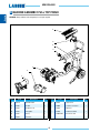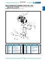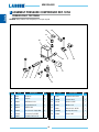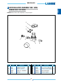
1
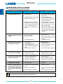
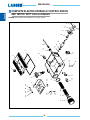
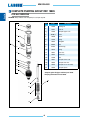
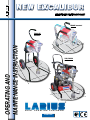
12 - 12
Ed. 009
NEW EXCALIBUR
ELECTRIC PISTON PUMP
Frame mounted
OPERATING AND
MAINTENANCE INSTRUCTION
Trolley
mounted
Top Finish
version
PA I N T
S P R AY I N G
EQUIPMENT
ENGLISH
Due to a constant product improvement programme, the factory reserves the right to modify technical
details mentioned in this manual without prior notice.
This manual is to be considered as an English language translation of the original manual in Italian.
The manufacturer shall bear no responsibility for any damages or inconveniences that may arise due
to the incorrect translation of the instructions contained within the original manual in Italian.
NEW EXCALIBUR
P REPLACEMENT OF THE PUMPING
INTRODUCTION................................................... p.1
A
B
C
D
E
WARNINGS........................................................... p.2
GROUP’S GASKETSE.......................................... p.22
WORKING PRINCIPLE......................................... p.3
Pit stop maintenance........................................ p.23
TECHNICAL DATA................................................. p.4
Replacing the foot valve seals........................... p.23
DESCRIPTION OF THE EQUIPMENT.................. p.5
Replacing the pump unit housing gasket.......... p.24
TRANSPORT AND UNPACKING.......................... p.10
Replacing the pump unit stem gasket............... p.26
SAFETY RULES.................................................... p.10
Correct positioning of the pump unit................. p.29
Electrical safety precautions............................. p.11
spare parts
Conditions of guarantee.................................... p.11
Q RECIRCULATING-SAFETY VALVE GROUP
F SETTING-UP......................................................... p.12
REF. 16400............................................................ p.35
Connection of the flexible hose to the gun........ p.12
Connection of the tooling to the power supply.. p.13
R REDUCTION GEAR.............................................. p.36
S FRAME.................................................................. p.37
T TROLLEY.............................................................. p.37
Preparation of the paint..................................... p.15
U ELECTRO-CONTROL DEVICE HYDRAULIC.
Check on power supply..................................... p.12
G WORKING............................................................. p.15
COMPLETE REF. P.38 18770 AND 18771............ p.38
V
W
X
Y
Z
AA
AB
AC
AD
AE
Start of the painting operations......................... p.15
Spray adjustment.............................................. p.16
Alarms............................................................... p.17
H CLEANING AT THE END OF THE WORK............ p.17
I GENERAL MAINTENANCE.................................. p.18
L ROUTINE MAINTENANCE................................... p.18
Check on the packing unit................................. p.18
M GENERAL MAINTENANCE.................................. p.19
N PROBLEMS AND SOLUTIONS............................ p.20
O CORRECT PROCEDURE OF
COMPLETE PUMPING GROUP........................... p.40
TOP FINISH ASSEMBLY....................................... p.42
COMPRESSOR..................................................... p.43
PRESSURE........................................................... p.44
AIR REGULATOR.................................................. p.45
AIR TANK............................................................... p.46
TROLLEY TOP FINISH......................................... p.47
ELECTRIC MOTOR............................................... p.48
ACCESSORIES..................................................... p.49
VERSIONS............................................................ p.54
DECOMPRESSION............................................... p.21
WE ADVISE THE USE OF THIS EQUIPMENT ONLY BY PROFESSIONAL OPERATORS.
ONLY USE THIS MACHINE FOR USAGE SPECIFICALLY MENTIONED IN THIS MANUAL.
Thank you for choosing a LARIUS S.R.L. product.
As well as the product purchased,
you will receive a range of support services
enabling you to achieve the results desired,
quickly and professionally.
1
English
ELECTRIC PISTON PUMP
NEW EXCALIBUR
English
WARNINGS
The table below provides the meaning of the symbols used in this manual in relation to using, earthing,
operating, maintaining, and repairing of this equipment.
Read this operator’s manual carefully before using the equipment.
An improper use of this machine can cause injuries to people or things.
Do not use this machine when under the influence of drugs or alcohol.
Do not modify the equipment under any circumstances.
Use products and solvents that are compatible with the various parts of the equipment, and read the manufacturer’s warnings carefully.
See the Technical Details for the equipment given in the Manual.
Check the equipment for worn parts once a day. If any worn parts are found, replace them using ONLY original spare parts.
Keep children and animals away from work area.
Comply with all safety standards.
It indicates an accident risk or serious damage to equipment if this warning is not followed.
It indicates a fire or explosion risk if this warning is not followed.
Eliminate all ignition sources such as pilot lights, cigarettes, portable electric lamps and plastic drop cloths.
Keep work area free of debris.
ONLY use this equipment in a well ventilated area.
EARTH ALL THE EQUIPMENT LOCATED IN THE WORK AREA.
Do not form connections or switch light switches on or off if the air contains inflammable fumes.
If electrical shocks or discharges are encountered the operation being carried out using the equipment must be stopped immediately.
Keep a fire extinguisher at hand in the immediate vicinity of the work area.
It indicates wound and finger squashing risk due to movable parts in the equipment.
Tenersi lontano dalle parti in movimento.
Do not use the equipment without the proper protection.
Before any inspection or maintenance of the equipment, carry out the decompression procedure explained in this manual, and prevent
any risk of the equipment starting unexpectedly.
Report any risk of chemical reaction or explosion if this warning has not been given.
There is a risk of injury or serious lesion related to contact with the jet from the spray gun. If this should occur, IMMEDIATELY contact
a doctor, indicating the type of product injected.
Do not spray before the guard has been placed over the nozzle and the trigger on the spray gun.
Do not put your fingers in the spray gun nozzle.
Once work has been completed, before carrying out any maintenance, complete the decompression procedure explained in this manual.
It indicates important recommendations about disposal and recycling process of products in accordance with the environmental regulations.
Report any danger of electric shock if the warning and presence of live electrical parts has not been indicated.
Store in a dry place and do not expose to the rain.
Check that the cables are in good condition.
Switch off the equipment and discharge any electricity before cleaning or maintaining the equipment.
Mark any clamps attached to earth cables.
Use ONLY 3-wire extension cords and grounded electrical outlets.
Before starting work make sure that the electrical system is earthed and that it complies with safety standards.
It is obligatory to wear suitable clothing as gloves, goggles and face shield.
Wear clothing that complies with the safety standards in force in the country in which the equipment is used.
Do not wear bracelets, earrings, rings, chains, or anything else that may hinder the operator’s work.
Do not wear clothing with wide sleeves, scarves, ties, or any other piece of clothing that could get tangled up in moving parts of the
equipment during the work, inspection, or maintenance cycles.
2
NEW EXCALIBUR
A WORKING PRINCIPLE
allows to adjust and control the pressure of the material coming
out of the pump.
When the pump reaches the set value, the motor stops and starts
again when the value decreases.
A safety valve avoiding overpressure, guarantees the total reliability
of the equipment.
“Top Finish” version.
“Top Finish” version allows to choose between Airless and
Mistless painting.
The machine works with basic system Mistless and to choose the
airless system it is necessary to close the air supply and replace
the type of spraying gun.
Frame mounted
Top Finish
version
Trolley mounted
Fields of application
Applications materials
Indoor
Lacquer
Paints
Outdoor
Waterborne
Emulsions
Industrial buildings
Acrylic
Impregnants
Industrial constructions
Primer
Antirust
Redeveloping
Enamels
Primer
Roofing
Fixative
3
English
The NEW J11
EXCALIBUR unit is defined “electric piston pump”.
An electric piston pump is used for high pressure painting without
air (from this process derives the term ”airless”).
The pump is controlled by an electric motor coupled with a reduction gear.
A cam shaft and a connecting rod allow to obtain the reciprocating
motion necessary to the working of the “pumping group” piston.
The piston movement produces a “vacuum”.
The product is sucked, pushed towards the pump outlet and then
sent to the gun through the flexible hose.
A electronical device on the side of the reduction gear casing,
NEW EXCALIBUR
English
B TECHNICAL DATA
NEW EXCALIBUR
SUPPLY (single-phase)*
RUN GENERATOR SUPPLY
Frame mounted
Trolley mounted
Top Finish version
230Vac - 50Hz
230Vac - 50Hz
230Vac - 50Hz
minimum 4Kw asynchronous minimum 4Kw asynchronous
minimum 4Kw asynchronous
MOTOR POWER
0,75 kW
0,75 kW
0,75 kW
MAX. WORKING PRESSURE
210 bar
210 bar
210 bar
2,1 L/min
2,1 L/min
2,1 L/min
M16 x 1,5 (M)
M16 x 1,5 (M)
M16 x 1,5 (M)
MAX DIM. OF THE GUN NOZZLE
0,023”
0,023”
0,023”
WEIGHT
17 Kg
18 Kg
65 Kg
≤ 80dB(A)
≤ 80dB(A)
≤ 80dB(A)
WIDTH
(A) 450 mm
(B) 460 mm
(A) 580 mm
(B) 540 mm
(A) xx mm
(B) xx mm
HEIGHT
(C) 550 mm
(C) 995 mm
(C) xx mm
0-40 Mpa
0-40 Mpa
0-40 Mpa
4,0 Kw monophase
4,0 Kw monophase
9,0 Kw monophase
-
-
1Kw-1,4HP-230lt./min.
-
-
5 lt.
-
-
0 ÷ 4 bar
MAX. DELIVERY
MATERIAL OUTLET
LEVEL OF THE SOUND PRESSURE
LENGTH
HIGH PRESSURE MANOMETER
GENERATOR MIN. REQUIREMENTS
AIR COMPRESSOR
AIR TANK
AIR SPRAY REGULATOR
*Available on request with special voltages
PARTS OF THE PUMP IN CONTACT WITH THE MATERIAL Stainless Steel AISI 420B, PTFE; Aluminium
4
NEW EXCALIBUR
C
English
Frame mounted
Trolley mounted
B
C
A
B
Top Finish
version
C
A
B
A
5
NEW EXCALIBUR
English
C DESCRIPTION OF THE EQUIPMENT
Frame mounted
15
1
14
2
8
7
3
9
5
10
4
6
13
16
12
8
5
7
11
POS.
1
2
3
4
5
6
7
8
10
Description
POS.
Recirculation tube
Output product recirculation
Safety-recirculation valve
Suction filter
Plug filter
Pumping group
ON/OFFswitch
Potentiometer for adjusting the operating pressure
9
10
11
12
13
14
15
16
6
Description
Intake product pipe
Attack for product delivery
Indicator light alarms
Airless manual gun
Trigger safety clamp
Reduction box
Handle
Frame
NEW EXCALIBUR
English
Trolley mounted
17
20
18
19
21
POS.
Description
POS.
Description
17
Recirculation piping with fittings
20
Trolley
18
Union
Dip hose
21
Wheel
19
7
NEW EXCALIBUR
English
Top Finish version
22
26
23
25
27
28
24
29
23
30
POS.
22
23
24
25
26
Description
POS.
Version Top Finish
Air regulator
Air tank
Mist-less 09 hand gun
Carter
27
28
29
30
8
Description
Compressor unit
Wheels
Pressure switch
Manometer
NEW EXCALIBUR
English
9
9
English
NEW EXCALIBUR
D TRANSPORT
AND UNPACKING
• The packed parts should be handled as indicated in the
symbols and markings on the outside of the packing.
•
•
Before installing the equipment, ensure that the area to
be used is large enough for such purposes, is properly
lit and has a clean, smooth floor surface.
Read carefully and entirely the following instructions before using the product. Please save these
instructions in a safe place.
The user is responsible for the operations of unloading
and handling and should use the maximum care so as
not to damage the individual parts or injure anyone.
To perform the unloading operation, use only qualified
and trained personnel (truck and crane operators, etc.)
and also suitable hoisting equipment for the weight of
the installation or its parts.
Follow carefully all the safety rules.
The personnel must be equipped with the necessary
safety clothing.
• The manufacturer will not be responsible for the unloading operations and transport to the workplace of
the machine.
• Check the packing is undamaged on receipt of the
equipment. Unpack the machine and verify if there
has been any damage due to transportation.
In case of damage, call immediately LARIUS and the
Shipping Agent. All the notices about possible damage
or anomalies must arrive timely within 8 days at least
from the date of receipt of the plant through Registered
Letter to the Shipping Agent and to LARIUS.
The disposal of packaging materials is a customer’s
competence and must be performed in accordance
with the regulations in force in the country where the
plant is installed and used.
It is nevertheless sound practice to recycle packaging
materials in an environment-friendly manner as much
as possible.
The unauthorised tampering/replacement of one
or more parts composing the machine, the use of
accessories, tools, expendable materials other than
those recommended by the manufacturer can be
a danger of accident.
The manufacturer will be relieved from tort and
criminal liability.
•
KEEP YOUR WORK PLACE CLEAN AND TIDY. DISORDER
WHEREYOU ARE WORKING CREATES A POTENTIAL RISK
OF ACCIDENTS.
•
ALWAYS KEEP PROPER BALANCE AVOIDING UNUSUAL
STANCE.
•
BEFORE USING THE TOOL, ENSURE THERE ARE NOT
DAMAGED PARTS AND THE MACHINE CAN WORK PROPERLY.
•
ALWAYS FOLLOW THE INSTRUCTIONS ABOUT SAFETY
AND THE REGULATIONS IN FORCE.
•
Keep those who are not responsible for the equipment out of the work area.
•
NEVER exceed the maximum working pressure indicated.
•
NEVER point the spray gun at yourselves or at other people. THE CONTACT WITH THE CASTING
CAN CAUSE SERIOUS INJURIES. In case of injuries caused by the gun casting, seek immediate medical advice specifying the type of the product injected. Never undervalue a wound caused by the injection of a fluid.
•
Always DISCONNECT THE SUPPLY AND release the pressure in the circuit before performing any check or part replacement of the equipment.
NEVER MODIFY ANY PART IN THE EQUIPMENT. CHECK
REGULARLY THE COMPONENTS OF THE SYSTEM. REPLACE THE PARTS DAMAGED OR WORN.
E SAFETY RULES
•
The employer shall train its employees about all those risks stemming from accidents, about the use of safety devices for their own safety and about the general rules for accident prevention in compliance with international regulations and with the laws of the country where the plant is used.
The behaviour of the employees shall strictly comply with the Accident prevention AND ALSO
ENVIRONMENTAL regulations in force in the country where the plant is installed and used.
•
10
NEW EXCALIBUR
•
•
• Check the switch is on the "OFF" position before connecting
the cable to the mains.
Always use the flexible hose supplied with standard kit. THE USE OF ANY ACCESSORIES OR TOOLING
OTHER THAN THOSE RECOMMENDED IN THIS MANUAL,
MAY CAUSE DAMAGE OR INJURE THE OPERATOR.
The fluid contained in the flexible hose can be very dangerous. Handle the flexible hose carefully. Do not pull the flexible hose to move the equipment. Never use a damaged or a repaired flexible HOSE.
The high speed of travel of the product in the hose
can create static electricity through discharges
and sparks.
It is suggested to earth the equipment.
The pump is earthed through the earth cable of
the supply.
The gun is earthed through the high pressure
flexible hose.
All the conductors near the work area must be
earthed.
•
Never carry a plugged-in equipment.
•
Disconnect the equipment before storing it and before performing any maintenance operation or replacing of accessories.
•
Do not carry the equipment neither unplug it by pulling the
electric cable.
•
Protect the cable from heat, oil and sharp edges.
•
When the tool is used outdoors, use only an extension cable
suited for outdoor use and so marked.
Never attempt to tamper with the calibre of instruments.
•
NEVER SPRAY OVER FLAMMABLE PRODUCTS OR SOLVENTS IN CLOSED PLACES.
•
Take care when the pumping rod is moving.
Stop the machine whenever someone is within its vicinity.
•
NEVER USE THE TOOLING IN PRESENCE OF POTENTIALLY EXPLOSIVE GAS.
•
Repairs of the electrical equipment should only be carried
out by skilled personnel, otherwise considerabledanger to
the user may result.
Always check the product is compatible with the
materials composing the equipment (pump, spray
gun, flexible hose and accessories) with which it
can come into contact. Never use paints or solvents containing halogen hydrocarbons (as the
methylene chloride).
If these products come into contact with aluminium
parts can provoke dangerous chemical reactions
with risk of corrosion and explosion.
condiTIONS OF GUARANTEE
The conditions of guarantee do not apply in the
following situations:
- improper washing and cleaning of components
causing malfunction, wear or damage to the
equipment or any of its parts;
- improper use of the equipment;
- use that does not conform with applicable national
legislation;
- incorrect or faulty installation;
- modifications, interventions and maintenance that
have not been authorised by the manufacturer;
- use of non-original spare parts or parts that do
not correspond to the specific model;
- total or partial non-compliance with the instructions provided.
IF THE PRODUCT TO BE USED IS TOXIC, AVOID
INHALATION AND CONTACT BY USING PROTECTION GLOVES, GOGGLES AND PROPER
FACE SHIELDS.
TAKE PROPER SAFETY MEASURES FOR THE
PROTECTION OF HEARING IN CASE OF WORK
NEAR THE PLANT.
11
English
•
Electrical safety precautions
Tighten and check all the fittings for connection between pump, flexible hose and spray gun before using the equipment.
NEW EXCALIBUR
English
F SETTING-UP
CHECK ON POWER SUPPLY
CONNECTION OF THE FLEXIBLE HOSE TO THE GUN
Make sure that the electrical system is earthed and
complies with regulations.
• Connect the high pressure flexible hose (F1) to the pump (F2)
and to the gun (F3) ensuring to tighten the fittings (the use of
two wrenches is suggested).
NEVER use sealants on fittings’ threads.
It is ADVISED to mount a high pressure manometer at the
pump outlet (see on page “Accessories”) to read the product
pressure.
• It is recommended to use the hose provided with the standard
kit (ref. 18036).
NEVER use a damaged or a repaired flexible hose.
F2
•
Check the mains voltage corresponds to the equipment’s
rating.
•
The supply cable is provided without plug.
Use a plug which guarantees the plant earthing.
Only a technician or a skilled person should perform the
connection of the plug to the electric cable.
F1
Should anyone use an extension cable between
the tooling and the socket, it must have the same
characteristics as the cable supplied (minimum
diameter of the wire 2.5 mm2) with a maximum
length of 50 mt. Higher lengths and lower diameters can provoke excessive voltage falls and also
an anomalous working of the equipment
F3
12
NEW EXCALIBUR
CONNECTION OF THE TOOLING TO THE POWER SUPPLY
• Press the switch (F4) of the equipment “ON” (I).
Check the switch (F4) is on the “OFF” (0) position before
connecting the cable to the mains.
•
Place the pressure control knob (F5) on the “MIN” position (turn counterclockwise).
•
Turn clockwise the pressure control knob (F5) so as the
machine works at idle speed.
ON
OFF
F5
F4
F4
•
F5
Ensure the gun (F3) is without nozzle.
MIN
F3
13
PRESSIONE
PRESSURE
MAX
English
•
NEW EXCALIBUR
•
•
Open the recirculating-safety valve (F6).
English
F6
Visually check that the wash fluid starts to re-circulate within
the tank (F7).
F7
F6
F6
•
CLOSED
It sprays out of the spray
gun
•
OPEN
It re-circulates back into
the tank without spraying
•
Turn the pressure adjustment handle (F5) clockwise to stop
the pump.
Closed the recirculating-safety valve (F6).
Turn the pressure setting knob (F5) clockwise to the “CIRCULATION & WASHING” position (drop symbol).
F5
Circulation and
washing
F5
•
MIN
PRESSIONE
PRESSURE
Turn pressure regulating knob (F5) clockwise a little so that
the machine idles.
MAX
Circulation
and washing
MIN
F5
14
F5
PRESSIONE
PRESSURE
MAX
NEW EXCALIBUR
• Point the gun (F3) into a container (F8) keeping the trigger
pressed (so as to drain the oil inside) till a clean solvent comes
out. Now, release the trigger.
G WORKING
English
START OF THE PAINTING OPERATIONS
• Use the tooling after performing all the SETTING UP operations above described.
F3
F8
• Dip the suction pipe (G1) into the product tank.
• Remove the suction pipe and take away the solvent tank.
• Point the gun into the solvent tank and press the trigger so
as to recover the residual solvent.
• As the pump idles, press the “OFF” (0) switch to stop the
tooling.
G1
Absolutely avoid to spray solvents indoors. In
addition, it is recommended to keep away from
the pump in order to avoid the contact between
the solvent fumes and the electric motor.
•
•
•
Open the recirculating-safety valve (G2) (turn clockwise so
as the pin slides on the cam track).
G2
Now the machine is ready. Should you use water paints,
besides the solvent wash, a wash with soapy and then clean
water is suggested.
Insert the gun trigger lock and assemble the nozzle.
PREPARATION OF THE PAINT
• Make sure the product is suitable to be used with a spray gun.
• Mix and filter the product before using it. For filtration, use
CLOSE-MESH (ref. 214) and LARGE-MESH (ref.215) LARIUS METEX braids.
G2
G2
Make sure the product to be used is compatible
with the materials employed for manufacturing the
equipment (stainless steel and aluminium).
Because of that, please contact the supplier of the
product.
CLOSED
It sprays out of the spray
gun
Never use products containing halogen hydrocarbons (as methylene chloride). If these products come into contact with aluminium
parts of the equipment, can provoke dangerous chemical reactions
with risk of explosion.
15
OPEN
It re-circulates back into
the tank without spraying
NEW EXCALIBUR
English
•
Press the switch “ON” (I) of the equipment and turn a little
the pressure control knob clockwise (G3), so as the machine
works at the idle speed.
•
Close the recirculating-safety valve (G2) (turn clockwise till
the valve has released).
G2
G3
•
•
Now the machine carries on sucking the product till the flexible
hose is full, up to the gun.
Then it will stop automatically.
Adjust the work pressure with the knob (G3).
SPRAY ADJUSTMENT
MIN
•
PRESSIONE
PRESSURE
•
Slowly turn clockwise the pressure control knob to reach the
pressure value in order to ensure a good atomization of the
product.
•
An irregular and marked spray on the sides indicates a low
working pressure. On the contrary, a too high pressure causes
a high fog (“overspray”) and waste of product.
•
In order to avoid overthickness of paint, let the gun advance
sideways (right-left) when spraying.
•
Always paint with regular parallel bands coats.
•
Keep a safety and constant distance between the gun and the
support to be painted and also keep yourselves perpendicular
to it.
MAX
Make sure the product recycles from the return tube (G4).
Never point the spray gun at yourselves or at
other people.
The contact with the casting can cause serious
injuries.
In case of injuries caused by the gun casting, seek
immediate medical advice specifying the type of
the product injected.
G4
Recirculating-safety valve: when working at the
maximum pressure available, releasing the gun
trigger sudden increases of pressure can occur.
In this case, the recirculating-safety valve opens
automatically eliminating part of the product from
the recirculating tube.
Then it closes so as to go back to the first working
conditions.
16
NEW EXCALIBUR
ALARMS
Flashing lamp (G4) for alarms:
English
•
H1
H2
•
G5
LED
•
ALARMS
1
Maximum current exceeded
2
Overheating Head Control
3
Overheating motor
(not implemented)
4
High voltage feeding current
H3
•
5
Low voltage feeding current
6
No earthing
7
Faulted pressure sensor
Release the residual pressure by holding down the trigger of
the gun and pointing it into a container.
Open the recirculating-safety valve (H3) to release the pressure
in the circuit.
•
•
•
•
•
Lift the suction pipe and replace the product tank with that
of the solvent (ensure it is compatible with the product being
used).
Unscrew the gun nozzle (do not forget to clean it with solvent).
Press the switch (H2) ON and turn a little the pressure
control knob (H1) clockwise so as the machine works till
the motor starts.
Make sure the solvent recycles the washing fluid from the
return tube.
Close the recirculating-safety valve (H3).
Point the gun (H4) into the product tank (H5) and, keeping
the trigger pressed, release the remaining product till a clean
solvent comes out. Now, release the trigger.
H4
8
Recycling stop (after 15 min.)
H5
H CLEANING AT THE END OF THE WORK
• Reduce pressure to the minimum (turn counterclockwise the
pressure control knob (H1) ).
•
Press the switch (H2) placed on the box of the electric motor,
to stop the equipment.
17
English
NEW EXCALIBUR
•
•
•
•
Lift again the suction pipe and remove the solvent tank.
Now point the gun into the solvent tank and press the trigger
so as to recover the residual solvent.
As the pump starts idling, press the switch OFF (0) to
stop the equipment.
In case of long storage, we recommend you to suck and to
leave light mineral oil inside the pumping group and the flexible
hose.
Follow the washing procedure before using again
the equipment.
L ROUTINE MAINTENANCE
CHECK ON THE PACKING NUT
Daily check the packing nut is tight in order to avoid wastes but
not excessively to prevent the piston from seizing and the
gaskets from wearing.
• For tightening, use the wrench supplied (ref. 11503).
Ref. 11503
Dowel
Oil ring
I GENERAL MAINTENANCE
ALWAYS DISCONNECT THE POWER SUPPLY
AND RELEASE THE PRESSURE IN THE PUMPING
GROUP (open the drain valve) BEFORE TIGHTENING THE PACKING NUT.
Discharge the pressure in the pump unit (open
the discharge valve) before carrying out any
maintenance.
DAILY •
•
•
•
Clean the filters;
Clean the nozzles;
Clean all the varnish circuit with a specific product;
Check the fuel motor (see the maintenance table).
•
PERIODICALLY
• Check the pumping gaskets draft (if the product draws, replace
gaskets);
• Clean the mobile parts from the varnish deposits (spray guns,
etc.);
• Check that the tubes and all the fittings are correctly locked.
Use the lubricant supplied (ref. 16325) to allow an easy sliding
of the piston inside the gasket group.
Daily top up the packing nut.
Ref. 16325
18
NEW EXCALIBUR
M WARNING PLATE
English
Code 16801
Code 16859
Code 16858
Code 16850
Code 18044
Code 32038
Code 16856
Code 16852
Code 16854
19
NEW EXCALIBUR
English
N PROBLEMS AND SOLUTIONS
Problem
•
The equipment does not start
• Lack of voltage;
• Considerable drops in mains voltage;
• On/Off switch disconnected;
•
•
•
•
•
•
The equipment does not suck the
product
The equipment sucks but does not
reach the pressure desired
Solution
Cause
Breakdown of pressure transmitter;
Breakdown of motor electric control box;
The line of material coming out of the
pump is already under pressure;
The product is solidified inside the
pump;
• Check the correct connection to the
power supply;
• Check the extension cable;
• Ensure the On/Off switch is on the
“on” position and turn clockwise the
pressure control knob;
• Verify and replace it, if necessary;
• Verify and replace it, if necessary;
• Open the drain valve to release
pressure in the circuit;
• Open the drain valve to release
pressure in the circuit and stop the
machine. Disassemble the pumping
group and the pressure transmitter
and clean;
•
•
Suction filter clogged;
Suction ilter too fine;
•
•
•
The equipment sucks air;
•
Clean or replace it;
Replace it with a larger-mesh filter
(with very dense products, remove
the filter);
Check the suction pipe;
•
•
•
•
•
•
•
•
Add the product;
Check the suction pipe;
Close the recirculating-safety valve;
Replace the gaskets;
•
Lack of product;
The equipment sucks air;
The recirculating-safety valve is open;
The gaskets of the pumping group are
worn;
Suction or delivery valve dirty;
•
Disassemble the pumping group;
•
When pressing the trigger, the
pressure lowers considerably
•
•
•
Nozzle too big or worn;
The product is too dense;
The filter of the gun-butt is too fine;
•
•
•
Replace it with a smaller one;
Dilute the product, if possible;
Replace it with a larger-mesh filter;
•
The pressure is normal but the
product is not atomized
•
•
•
The nozzle is partially clogged;
The product is too dense;
The filter of the gun-butt is too fine;
•
•
•
Clean or replace it;
Dilute the product, if possible;
Replace it with a larger-mesh filter;
•
The atomization is imperfect
•
The nozzle is worn;
•
Replace it;
•
When releasing the trigger of the
gun, the equipment does not stop
(the motor runs slowly and the
piston rod keeps on going up and
down)
•
•
Replace the gaskets;
•
The gaskets of the pumping group are
worn;
Suction or delivery valve dirty;
•
•
Recirculating-safety valve defective;
•
Disassemble the pumping group and
clean;
Verify and replace it, if necessary;
Always close the air compressed supply and unload the plant pressure before performing any check or replacement of pump parts (see "correct procedure of decompression").
20
NEW EXCALIBUR
O CORRECT PROCEDURE OF
DECOMPRESSION
•
Disconnect the power supply cable (O4).
English
• Insert the gun clamp (O1).
O4
O1
Clamp inserted
Clamp released
•
Move the switch (O2) to the OFF position to stop the equipment.
• Reduce pressure to the minimum (turn counterclockwise the
pressure control knob (O3)).
•
Release the gun clamp (O1), point the gun into the tank of
the product and press the trigger to release pressure. At the
end of the operation, insert the gun clamp.
•
Open the recirculating-safety valve (O5) to release the residual
pressure always clockwise.
O5
OFF
O2
WARNING :
If the equipment is still under pressure after performing the operations above described because
of the nozzle or the flexible hose clogged, proceed
as follows:
• Loosen very slowly the gun nozzle.
• Release the clamp.
• Point the gun into the container of the product
and press the trigger to release pressure.
• Loosen very slowly the fitting of connection
from the flexible hose to the gun.
• Clean or replace the flexible hose and the
nozzle.
O3
21
NEW EXCALIBUR
English
P REPLACEMENT OF THE PUMPING GROUP’S GASKETS
•
P5
Carry out this operation after cleaning the tooling.
P6
Always disconnect the power supply and release
pressure before going on with the operations
(follow the “correct procedure of decompression”).
•
Use a 19 mm spanner to unscrew the ring nut (P1) on the
feed pipe in order to make the operation easier.
•
Unscrew the fixing ring nut (P7), to the end of the thread using
a 45 mm spanner.
P7
P1
•
•
Release the plastic covering (P2).
Use a screwdriver (P3) to turn the motor(P4) until the piston
stem is at the bottom of its stroke and then move the con-rod
to a position in which it can be reached to remove it.
•
P2
Unscrew the suction casing using a 32 mm spanner as
illustrated. If necessary, remove the suction pipe (P8) before
continuing with the other operations.
P4
P3
P8
•
Remove the locking pin (P5) using pliers (P6).
22
NEW EXCALIBUR
•
English
•
Disconnect the pumping group by unscrewing the fastening
nut (wrench 45).
Unscrew the pumping group from the housing. You can now work easily as the pump casing has been freed.
•
Grip the complete pump unit (P9) in a vice (P10) (as shown).
P10
•
P9
Remove the pump unit (P13) from the foot valve (P14) as
shown.
Inspect the two parts separately.
P13
P14
•
Slacken the ring nut (P11) by two full turns using the special
pin (P12) supplied.
Turn anticlockwise as shown.
P11
PIT STOP MAINTENANCE
Replacement of upper and lower gaskets 25 minutes.
P12
REPLACING THE FOOT VALVE SEALS
• Replace the PTFE gasket (P15) located under the ball seating (P16).
•
Use a 36 mm spanner to unscrew the pump unit as shown.
23
•
Check that the surfaces of the ball seating (P16) and the ball
(P17) are not damaged. If necessary, replace both of them.
•
Fit them again using the component sequence shown.
NEW EXCALIBUR
•
English
P15
Unscrew the gasket compression ring nut (P20) completely.
All the gaskets in the unit must be replaced at the same
time to allow the machine to work properly.
P20
P17
P16
REPLACING THE PUMP UNIT HOUSING UPPER GASKET
•
Remove the piston stem (P18) from the pump unit housing (P19) as shown.
•
Remove the upper stainless steel female ring (P21) as shown.
P21
P18
P19
P21
24
NEW EXCALIBUR
•
Remove the series of gaskets contained inside the pump unit
housing, as shown.
4
English
Grey polyethylene
5
1
Upper white
PTFE
Lower white PTFE
2
•
Remove the lower stainless steel male ring (P22) as shown.
P22
Grey polyethylene
3
•
Waxed leather
25
Fit the new gasket kit according to the component sequence
shown in the figure.
NEW EXCALIBUR
P
P
E
R
English
U
P23
P24
REPLACING THE PUMP UNIT STEM GASKET
Steel female ring
Code 16106
•
Secure the stem (P19) in a vice as shown.
PTFE white
Code 16107
P19
Polyethylene grey
Code 16124
Waxed leather
Code16155
Polyethylene grey
Code 16124
PTFE grey
Code 16107
Steel male ring
Code 16108
•
Remove the PTFE O-ring (P23) and replace it with a new one
(P24).
26
NEW EXCALIBUR
Use a 10 mm spanner to unscrew and remove the stem (P19)
as indicated.
•
Remove the complete gasket kit (P25) from the stem (P19),
as shown, in order to replace it.
L
O
W
E
P19
Steel male ring
Code 18644
PTFE white
Code 16117
P19
P25
Polyurethane red
Code 16114
PTFE White
Code 16177
Polyethylene grey
Code 16136
Steel female ring
Code 18645
•
R
English
•
PTFE scraper ring
Code 18648
Fit the new gasket kit according to the component sequence
shown in the figure.
Check the scraper for wear (Ref. 18648).
Replace if necessary.
27
English
NEW EXCALIBUR
•
Replace the grey polyethylene lipped gasket (P26) for the
valve piston.
•
Refit according to the assembly order and the alignment of
the lip (as shown).
Check the surfaces of the ball (P27) and ball seating (P28),
and replace both if damaged.
P27
P28
P29
•
Insert the stem (P19) into the housing (P18) rotating it as you
do so in order to allow it to slide more easily and to avoid
damaging the upper gaskets.
P19
•
Assemble the components as shown.
•
•
P18
Lubricate the O-ring (P30) (Ref. 16126) with grease, as shown.
Vaseline is recommended for this task.
Lubricate the gaskets (P29) and the stem.
Vaseline is recommended for this task.
P30
28
NEW EXCALIBUR
•
Put liquid PTFE on the first two turns(P31) and (P32) to avoid
the two components coupled as shown from unscrewing.
•
Make the piston stem (P19) fitted previously complete a full
stroke as shown.
English
P19
P32
P31
•
Use the pin (P12) supplied to tighten the gasket compression
ring nut (P11).
Close this until it is fully touching, without forcing.
P11
P12
•
Use a 36 mm spanner to screw on the pump unit (P10).
P10
CORRECT POSITIONING OF THE PUMP UNIT
Once the unit has been refitted, proceed as follows:
29
•
Check the position of the con rod, which should be positioned
at its lower stopping point.
•
Put the entire pump unit (P10) inside the reduction cover
(P33) as shown.
NEW EXCALIBUR
Use a gauge to measure the gap between the base of the
template and the start of the tightening groove.
English
•
The reference value (see drawing) must be 18 mm.
The maximum tolerance accepted for correct operation is 21 mm maximum and 16 mm minimum.
P10
P33
P10
•
Centre the two holes (con rod + stem) and insert the stopping
pin (P35) inside the con rod (P34).
•
Check that the closing spring (P36) in the con rod (P34) goes
into the pin seating when closed (as shown).
P35
P34
max. 21mm
P36
•
Screw the entire pump unit (P10) inside the reduction cove.
30
Reference
Screw the entire pump unit onto the front template, making
sure that the end of the stem is centred in relation to the
groove in the con rod (P34).
18mm
•
mm
min. 16mm
18
NEW EXCALIBUR
•
•
P37
•
Close the inspection cover (P2) again.
P2
•
For correct reassembly, see the exploded diagram for the
pump unit, and invert the order used for disassembly.
English
Once the unit has been positioned correctly, tighten the lock
nut (P37) hard against the front template.
To tighten, use a 45 mm spanner.
Fit the suction pipe (P8).
Put PTFE tape or liquid PTFE over the threaded part (P39)
before screwing it onto the foot valve..
P8
P39
31
English
SPARE PARTS FRAME MOUNTED
SO Frame
pag. 37
electro-hydraulic control device
O Complete
U
Ref. 18770 and 18771
Page 38
assembly
O Drive
R
page 36
O Accessories
AD
page 49
O
AC
Electric motor
page. 48
pumping
VO Complete
page 40
valve group ref. 16400
O Recirculating-safety
Q
Page 35
32
SPARE PARTS TROLLEY MOUNTED
TO
Page 38
English
O
R
electro-hydraulic control device
O Complete
U
Ref. 18770 and 18771
Trolley
page 37
Drive assembly
page 36
O Accessories
AD
page 49
O
AC
Electric motor
page 48
pumping
VO Complete
page 40
valve group
O Recirculating-safety
Q
ref. 16400 page 35
33
English
SPARE PARTS TOP FINISH VERSION
YO
PRESSURE
page 44
O
AC
REGULATOR
ZO AIR
page 45
U
Complete electro-hydraulic control
device Ref. 18770 and 18771
Page 38
Electric motor
page 48
O Assembly
W
page 42
O
AB
Trolley
page 47
assembly
O Drive
R
page 36
O Accessories
AD
page 49
valve
O Recirculating-safety
Q
group ref. 16400
page 35
pumping
VO Complete
page 39
O
AA
X
AIR TANK
page 46
Compressor
page 43
34
Q RECIRCULATING-SAFETY VALVE GROUP REF. 16400
English
for all versions
WARNING: Always indicate code and quantity for each part required.
8
7
6
9
10
5
4
3
2
1
Pos.
Code
-
16400
Description
R e c i rc u l a t i n g - s a f e t y va l v e
group
1
4033
O-ring
2
16415
Valve housing
3
53007/3
O-ring
4
16419
Antiextrusion ring
5
16420
Material rod
6
16410
Spring
7
46409
Bush
8
16408
Dowel
9
16405
Knob
10
90018
Dowel
35
NEW EXCALIBUR
English
R DRIVE ASSEMBLY for all versions
WARNING: Always indicate code and quantity for each part required.
26
9
8
13
27
25
24
23
28
6
9
17
16
15
20
12
13
11
19
5
14
3
10
22
21
1
1A
7
10
4
2
2A
18
Pos.
Code
Description
Pos.
1
18660/220
Electric motor 220V 50Hz
14
18685
Scraper ring
1A
18660/110
Electric motor110V 60Hz
15
18666
Pin for connecting rod
2
18770
Compl. electro-hydraulic box 220V
16
18629
Tin plate door
2A
18771
Compl. electro-hydraulic box110V
17
9173
Screw
3
18650
Complete rod
18
18790
Complete h.p. hose for connection
4
18649
Complete sleeve
19
8029
Screw
5
18663
Cover
20
32005
Washer
6
18672
Complete toothed gear
21
8029
Screw
7
18680
Complete toothed driving gear
22
32005
Washer
8
18673
Complete connecting rod
23
7059
Screw
9
18667
Cam bushing
24
34009
Washer
10
18681
Driving cam
25
37406
Screw
11
18665
Spring
26
18686
Front label
12
18664
Bushing
27
18677
Warning label
13
4233
Centering pin
28
18044
Flashing label
36
Code
Description
NEW EXCALIBUR
S FRAME
2
1
Pos.
Code
Description
1
18765
Handle
2
18699
Handgrip
3
18698
Frame tube - left
4
18698A
Frame tube - right
5
37403
Frame cap
5
5
3
4
T TROLLEY
2
5
4
Pos.
Code
1
1
18765
Handle
3
4
5
4
2
18631
Handgrip
3
37406
Screw
4
34009
Washer
5
7059
Screw
6
91047
Washer firm wheel
7
37218
Wheel
8
18632
Frame
9
37403
Caps
6
7
6
7
8
9
9
37
Description
English
WARNING: Always indicate code and quantity for each part required.
U COMPLETE ELECTRO-HYDRAULIC CONTROL DEVICE
REf. 18770 e 18771 for all versions
27
28
1
2
21
12
3
19
13
20
14
15
16
17
22
18
29
WARNING: Always indicate code and quantity for each part required.
10
9
6
24
7
24
25
26
25
8
25
26
5
23
4
11
19
English
NEW EXCALIBUR
38
NEW EXCALIBUR
Pos.
Code
Q.ty
Pos.
Complete electro-hydrau-
1
13
18689
Orm
1
14
18684
Gasket
1
15
18692
Pressure sensor
1
16
18693
Potentiometer
1
lic control 220V/50Hz
18771
Complete electro-hydrau-
1
lic control 110V/60Hz
Code
Description
Q.ty
1
18688
Electro ID box
1
17
18682
Plug
1
2
18654
Cover box
1
18
18687
Pressure label
1
3
18625
Gasket
1
19
18871
Cable fastener
2
4
16400
Recirculating-safety valve
1
20
18870
Power cable
1
5
18654/220
Electronic card 220V
1
21
96208
Union
2
5
18654/110
Electronic card 110V
1
22
18694
Control knob
1
6
18580
Complete filter cap
1
23
18872
Spacer card
1
7
16205
Filter sieve
1
24
5379
Screw
2
8
18627
Filter sieve support
1
25
5339
Washer
3
9
18622
Or
1
26
5114
Nut
2
10
96206
Union
1
27
4019
Screw
4
11
18614
Union
1
28
5737
Washer
4
12
5933
Switch
1
29
95210
Dowel 1
39
English
18770
Description
NEW EXCALIBUR
English
V COMPLETE PUMPING GROUP REF. 18885
for all versions
WARNING: Always indicate code and quantity for each part required.
1
Pos.
Code
1
16109
Packing nut
2
16127
Lock nut
3**
*
4
16105
Complete upper seals
2
3
4
16
5
6
7
8
9
10
Description
96208/1
Union
5
18640
Sleeve
6**
16126
O-ring
7
18642
Ball guide
8**
33028
Ball
9
91018
Ball housing
10**
18675
O-ring
11
18641
Foot valve
12
18652
Piston rod
13**
16130
Ball
14**
*
15**
*
16
18651
Complete lower seals
18655
Complete foot valve
18649
Complete sleeve assembly
17
18650
Complete piston
11
* Complete gasket kit (upper and lower) cod. 18855
**Pumping maintenance kit cod. 40106
17
12
13
14
15
40
NEW EXCALIBUR
GASKETS ASSEMBLY
S E A L S
English
U P P E R
Steel female ring
Code 16106
PTFE white
Code 16107
Polyethylene grey
Code 16124
Waxed leather
Code16155
Code
16132
Code
16105
Code
16133
Code
18651
Polyethylene grey
Code 16124
PTFE grey
Code 16107
Steel male ring
Code 16108
L O W E R
S E A L S
Steel male ring
Code 18644
PTFE white
Code 16117
Polyurethane red
Code 16114
PTFE White
Code 16177
Polyethylene grey
Code 16136
Steel female ring
Code 18645
PTFE scraper ring
Code 18648
41
NEW EXCALIBUR
English
W MACHINE ASSEMBLY FULL TOP FINISH
WARNING: Always indicate code and quantity for each part required.
7
6
5
4
3
2
1
Pos.
Code
Description
Q.ty
Pos.
Code
Description
Q.ty
1
18774
Excalibur 230V
1
7
18797
Upper carter
1
2
18796
Air tank
1
-
16602
Junction connection
1
3
18793
Compressor air
1
-
18182
Dip hose
1
4
18795
Air regulator
1
-
37216
Stainless steel filter
1
5
18792
Trolley
1
-
18654/220
Electronic card
1
6
18794
Pressure
1
42
NEW EXCALIBUR
X AIR COMPRESSOR ASSEMBLY GROUP REF. 18793
English
version only TOP FINISH
WARNING: Always indicate code and quantity for each part required.
10
5
1
12
9
8
3
2
3
11
4
6
5
7
Pos.
Code
Description
Q.ty
Pos.
Code
Description
Q.ty
1
30542/1
Air compressor
1
7
6151
Screw TCE UNI 5931 M8x50
4
2
18798
Compressor bracket
1
8
8042
Nut locking UNI 7473 M6
4
3
5263
Washer UNI 6592 Ø 6
9
9
18784
Electrical box
1
4
91062
Screw TCE UNI 5931 M6x20
4
10
3637
Nut locking UNI 7473 M8
4
5
510026
Washer UNI 6592 Ø 8
8
11
32024/1
Washer Ø 8x24
4
6
96031
Screw TCE UNI 5931 M8x25
4
12
18463
Spacer
4
43
NEW EXCALIBUR
English
Y ASSEMBLY PRESSURE COMPRESSOR REF. 18794
version only TOP FINISH
WARNING: Always indicate code and quantity for each part required.
12
13
11
10
6
15
8
1
2
3
4
1
14
9
7
5
6
Pos.
Code
Description
Q.ty
Pos.
Code
Description
Q.ty
1
4515
Collar 1/2”
2
9
8167
BP Manometer 0-10 bar
1
2
8083
Cap 1/4”
1
10
30536
Pressure switch
1
3
22047
M-F Extension 1/4
1
11
18772
Extension 1/4” FF
1
4
33012
Copper Gasket 1/4”
1
12
5255
MF Elbow 1/4”
1
5
30559
Exhaust valve
1
13
4801
Reduction 3/8 - 1/4 FM
1
6
16053
Air connection 1/4 pipe Ø10
2
14
30559/1
One-way valve 3 way
1
7
22753
Connection T 1/4” MFF
1
15
22027
Extension MF
1
8
22027
Reduction M-F 1/4 - 1/8
1
44
NEW EXCALIBUR
Z AIR REGULATOR ASSEMBLY REF. 18795
English
version only TOP FINISH
WARNING: Always indicate code and quantity for each part required.
8
7
6
5
4
3
2
1
Pos.
Code
Description
Q.ty
Pos.
Code
Description
Q.ty
1
8167
BP Manometer 0-10 bar
1
5
16053
Air connection 1/4 pipe Ø10
1
2
3344
Regulator 1/4” 0-8 bar
1
6
54004
TCE Screw UNI 5931 M6x16
2
3
96028
Adapter 1/4 - 194 CON-CIL
1
7
950633
Washer Ø6 UNI 6592
2
4
4004
Ball valve
1
8
510510
Bracket for regulator
1
45
NEW EXCALIBUR
English
AA ASSEMBLY AIR TANK REF. 18796
version only TOP FINISH
WARNING: Always indicate code and quantity for each part required.
2
5
4
7
8
9
8
6
1
2
3
Pos.
Code
Description
Q.ty
Pos.
Code
Description
Q.ty
1
30540
Air tank
1
6
8042
Nut locking UNI 7473 M6
2
2
16053
Air connection 1/4 pipe Ø10
2
7
95063
Washer UNI 6592 Ø6
4
3
5255
Elbow 1/4” MF
1
8
20436
Screw TCE UNI 5931 M6x60
2
4
3365
Elbow 1/4” MM
1
9
18798
Spacer
2
5
9902
Check valve
1
46
NEW EXCALIBUR
AB ASSEMBLY TROLLEY REF. 18792
English
version only TOP FINISH
WARNING: Always indicate code and quantity for each part required.
1
2
3
4
5
6
7
8
Pos.
Code
Description
Q.ty
Pos.
Code
Description
Q.ty
1
30301
Handle
1
5
18902
Pin Ø6
2
2
95159
Pipe cap Ø30
2
6
37238
Wheel Ø260
2
3
18914
Bushing for trolley handle
2
7
20305
Wheel washer
2
4
18791
Trolley frame
1
8
30304
Caps Ø40
2
47
NEW EXCALIBUR
English
AC ELECTRIC MOTOR
WARNING: Always indicate code and quantity for each part required.
•
Periodically check the perfect connection among all the
electrical components (at least every 200 working hours).
•
The length of the brush contact must be higher than 9 mm
to guarantee a good working of the rotary group.
DISCONNECTTHE POWER SUPPLY BEFORE CHECKING OR REPLACING THE BRUSHES.
•
Periodically check on the wear of the pinion (at least every
1000 working hours).
1
2
m*
Pos.
Code
Description
1
18899
Brush 220V 50Hz
2
18879
Brush 110V 60Hz
3
16047
Brush holder plug
m**
24 m
9m
*Length of new brush
**Minimum length of the brush
Replace
48
NEW EXCALIBUR
AD ACCESSORIES
English
WARNING: Always indicate code and quantity for each part required.
7
1
8
9
4
11
10
2
5
6
3
12
13
Pos.
Code
Description
Pos.
Code
1
37600
2
Complete jointed fitting
8
18095
Spring
18350
Dispersion bell
9
18350
Dispersion bell
3
37216
Filter
10
16802
Filter
4
16602
Union
11
18375
Flexible hose
5
18182
Dip hose
12
18609
Nut
6
18370
Assembly
13
18608
Spring
7
18367
Recirculation pipe
49
Description
English
NEW EXCALIBUR
5
4
3
1
Pos.
Code
1
18026
2
Description
Pos.
Code
Delivery compensation hose length
3
96099
Intake sleeve
15 mt.
4
16081
Union
5
16082
Elbow
2
147
High pressure manometer M16x1,5
2
150
High pressure manometer GJ 1/4"
50
Description
NEW EXCALIBUR
English
Art. 19975: SPRAY GUN Mist-less 09
base Mist-clean
Code 11250: AT 250 1/4”+Fast Clean base
Code 11200: AT 250 M16x1,5+Fast Clean base
Code 16205: FILTER 60 MESH
Code 16204: FILTER 100 MESH
Code 16203: FILTER 200 MESH
Code 270: FILTER 100 MESH
Code 271: FILTER 60 MESH
PISTON GUNSTOCK FILTERS
Code 11039: Green (30M)
Code 11038: White (60M)
Code 11037: Yellow (100M) Code 11019: Red (200M)
Code 85014: FILTER 40 MESH
Code 85012: FILTER 20 MESH
Code 37215: FILTER 40 MESH inox
Code 37216: FILTER 20 MESH inox
51
English
NEW EXCALIBUR
ELECTRIC
MIXERS:
Code 217550:
MX 850 - 850W
Code 217560:
MX 1100 - 1080W
Code 217570:
MX 1100E - 1080W
ANTIPULSATIONS HOSE 1/4" - M16x1,5
max pressure 250 bar
Code 35013: 5 mt
Code 35014: 7,5 mt
Code 35017: 10 mt
Code 18026: 15 mt
HIGH PRESSURE HOSE 3/8" - M16x1,5 max pressure 425 bar
Code 18063: 7,5 mt
Code 18064: 10 mt
Code 18065: 15 mt
ANTISTATIC HOSE 3/16" - M16x1,5 max pressure 210 bar
Code 6164: 5 mt
Code 55050: 7,5 mt
Code 35018: 10 mt
52
NEW EXCALIBUR
Nozzles code
TOP-SPRAYING CLEAN
TSC 19-20
TSC 19-40
TSC 19-60
TSC 21-20
TSC 21-40
TSC 21-60
TSC 23-20
TSC 23-40
TSC 23-60
TSC 27-20
TSC 27-40
TSC 27-60
TSC 31-40
TSC 31-60
English
TSC 7-20
TSC 7-40
TSC 9-20
TSC 9-40
TSC 11-20
TSC 11-40
TSC 13-20
TSC 13-40
TSC 13-60
TSC 15-20
TSC 15-40
TSC 15-60
TSC 17-20
TSC 17-40
TSC 17-60
TOP-SPRAYING CLEAN TIP
Code 18280: GASKET
Code 18270: SUPER FAST-CLEAN base UE 11/16x16
Nozzles code
SUPER FAST-CLEAN
FAST-CLEAN TIP
07-20
07-40
09-20
09-40
11-20
11-40
13-20
13-40
13-60
15-20
15-40
15-60
17-20
17-40
17-60
19-20
19-40
19-60
21-20
21-40
21-60
23-20
23-40
23-60
25-20
25-40
25-60
27-20
27-40
27-60
27-80
29-20
29-40
29-60
Code 303: GASKET
Code 300: FAST-CLEAN base UE 11/16x16
53
29-80
31-40
31-60
31-80
33-40
33-60
33-80
39-40
39-60
39-80
43-40
43-60
43-80
51-40
51-60
51-80
English
NEW EXCALIBUR
GUN EXTENSION
Art. 153: cm 30 -Art. 153: cm 40 Art. 155: cm 60 - Art. 158: cm 80 - Art. 156: cm 100
PLA 1/4”
+ BASE SUPER
FAST-CLEAN
Art. K11420-K11425-K11430: cm 130-180-240
PLA M16x1,5
+ BASE SUPER
FAST-CLEAN
Art. K11421-K11426-K11431: cm 130-180-240
Art. 16780: TELESCOPIC PAINT ROLLER
complete with:
n. 1 Roller with extra-long fiber
n. 1 Roller with long fiber
n. 1 Roller with medium fiber
Flexible hose mt. 2 3/16 " M16x1,5
Art. 40107: Complete repairing kit for pumping unit
54
L’innovazione.
Quella vera.
PAINT SPRAYING EQUIPMENT
NEW EXCALIBUR
English
AE VERSIONS
Ref. 18775: FRAME MOUNTED WITHOUT SPRAYING ACCESSORIES 230 V
Ref. 18779: FRAME MOUNTED WITHOUT SPRAYING ACCESSORIES 115 V
Ref. 18776: TROLLEY MOUNTED WITHOUT SPRAYING ACCESSORIES 230 V
Ref. 18780: TROLLEY MOUNTED WITHOUT SPRAYING ACCESSORIES 115 V
Ref. K18775: FRAME MOUNTED WITH SPRAYING ACCESSORIES 230 V
Ref. K18779: FRAME MOUNTED WITH SPRAYING ACCESSORIES 115 V
Ref. K18776: TROLLEY MOUNTED WITH SPRAYING ACCESSORIES 230 V
Ref. K18780: TROLLEY MOUNTED WITH SPRAYING ACCESSORIES 115 V
56
NEW EXCALIBUR
English
Ref. 18777: FRAME MOUNTED WITH GRAVITY HOPPER WITHOUT ACCESSORIES 230 V
Ref. 18778: TROLLEY MOUNTED WITH GRAVITY HOPPER WITHOUT ACCESSORIES 230 V
Ref. K18778: TROLLEY MOUNTED WITH GRAVITY HOPPER
AND SPRAYING ACCESSORIES 230 V
57
AIRLESS PISTON PUMPS
NEW EXCALIBUR top finish Rif. 18783
JOLLY Rif. 56501
DRAGON Rif. 30184
THOR 220V/50Hz long pump unit Rif. 20705
THOR 220V/50Hz short pump unit Rif. 20700
ZEUS Rif. K35100
MANUFACTURER:
23801 CALOLZIOCORTE - LECCO - ITALY - Via Antonio Stoppani, 21
Tel. (39) 0341/62.11.52 - Fax (39) 0341/62.12.43
E-mail: [email protected] - Internet http://www.larius.com
DIRECT LINE
CUSTOMERS TECHNICAL SERVICE
Tel. (39) 0341/621256
Fax (39) 0341/621234