1
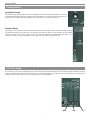
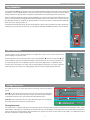
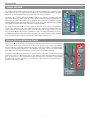
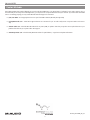
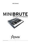
TimewARP 2600
Getting Started Guide
Table of Contents
Getting Started with the TimewARP 2600 . . . . . . . . . . . . . . . . . . . . . . . . . . . . . . . . . . . . . . . . . . . . . . . . . . . . . . . . . . . . . . . . . . . . . . . . . . . . . . 3
In this document, you’ll learn . . . . . . . . . . . . . . . . . . . . . . . . . . . . . . . . . . . . . . . . . . . . . . . . . . . . . . . . . . . . . . . . . . . . . . . . . . . . . . . . . . . . . . . 3
What Is an ARP 2600? . . . . . . . . . . . . . . . . . . . . . . . . . . . . . . . . . . . . . . . . . . . . . . . . . . . . . . . . . . . . . . . . . . . . . . . . . . . . . . . . . . . . . . . . . . . . . . . . . 3
Portable Modular Synthesizer . . . . . . . . . . . . . . . . . . . . . . . . . . . . . . . . . . . . . . . . . . . . . . . . . . . . . . . . . . . . . . . . . . . . . . . . . . . . . . . . . . . . . . 3
Why Synthesize? . . . . . . . . . . . . . . . . . . . . . . . . . . . . . . . . . . . . . . . . . . . . . . . . . . . . . . . . . . . . . . . . . . . . . . . . . . . . . . . . . . . . . . . . . . . . . . . . . . . . . . 4
Basic Waveforms . . . . . . . . . . . . . . . . . . . . . . . . . . . . . . . . . . . . . . . . . . . . . . . . . . . . . . . . . . . . . . . . . . . . . . . . . . . . . . . . . . . . . . . . . . . . . . . . . . . . . . 4
Modular Synths . . . . . . . . . . . . . . . . . . . . . . . . . . . . . . . . . . . . . . . . . . . . . . . . . . . . . . . . . . . . . . . . . . . . . . . . . . . . . . . . . . . . . . . . . . . . . . . . . . . . . . . 4
Synth Glossary . . . . . . . . . . . . . . . . . . . . . . . . . . . . . . . . . . . . . . . . . . . . . . . . . . . . . . . . . . . . . . . . . . . . . . . . . . . . . . . . . . . . . . . . . . . . . . . . . . . . . . . . 5
I/O Jacks . . . . . . . . . . . . . . . . . . . . . . . . . . . . . . . . . . . . . . . . . . . . . . . . . . . . . . . . . . . . . . . . . . . . . . . . . . . . . . . . . . . . . . . . . . . . . . . . . . . . . . . . . . . . . 6
Signal Flow . . . . . . . . . . . . . . . . . . . . . . . . . . . . . . . . . . . . . . . . . . . . . . . . . . . . . . . . . . . . . . . . . . . . . . . . . . . . . . . . . . . . . . . . . . . . . . . . . . . . . . . . . . . 6
Labels and Symbols . . . . . . . . . . . . . . . . . . . . . . . . . . . . . . . . . . . . . . . . . . . . . . . . . . . . . . . . . . . . . . . . . . . . . . . . . . . . . . . . . . . . . . . . . . . . . . . . . . . 7
Output Section . . . . . . . . . . . . . . . . . . . . . . . . . . . . . . . . . . . . . . . . . . . . . . . . . . . . . . . . . . . . . . . . . . . . . . . . . . . . . . . . . . . . . . . . . . . . . . . . . . . . . . . . 7
Mix/Pan/Reverb Output Module . . . . . . . . . . . . . . . . . . . . . . . . . . . . . . . . . . . . . . . . . . . . . . . . . . . . . . . . . . . . . . . . . . . . . . . . . . . . . . . . . . . . 7
Preamp Section . . . . . . . . . . . . . . . . . . . . . . . . . . . . . . . . . . . . . . . . . . . . . . . . . . . . . . . . . . . . . . . . . . . . . . . . . . . . . . . . . . . . . . . . . . . . . . . . . . . . . . . 8
Preamp/Gain Control . . . . . . . . . . . . . . . . . . . . . . . . . . . . . . . . . . . . . . . . . . . . . . . . . . . . . . . . . . . . . . . . . . . . . . . . . . . . . . . . . . . . . . . . . . . . . 8
Envelope Follower . . . . . . . . . . . . . . . . . . . . . . . . . . . . . . . . . . . . . . . . . . . . . . . . . . . . . . . . . . . . . . . . . . . . . . . . . . . . . . . . . . . . . . . . . . . . . . . . 8
VCO Fine-Tuning . . . . . . . . . . . . . . . . . . . . . . . . . . . . . . . . . . . . . . . . . . . . . . . . . . . . . . . . . . . . . . . . . . . . . . . . . . . . . . . . . . . . . . . . . . . . . . . . . . . . . . 8
VCO 1 . . . . . . . . . . . . . . . . . . . . . . . . . . . . . . . . . . . . . . . . . . . . . . . . . . . . . . . . . . . . . . . . . . . . . . . . . . . . . . . . . . . . . . . . . . . . . . . . . . . . . . . . . . . . . . . . . 9
VCO 2 . . . . . . . . . . . . . . . . . . . . . . . . . . . . . . . . . . . . . . . . . . . . . . . . . . . . . . . . . . . . . . . . . . . . . . . . . . . . . . . . . . . . . . . . . . . . . . . . . . . . . . . . . . . . . . . . 9
VCO 3 . . . . . . . . . . . . . . . . . . . . . . . . . . . . . . . . . . . . . . . . . . . . . . . . . . . . . . . . . . . . . . . . . . . . . . . . . . . . . . . . . . . . . . . . . . . . . . . . . . . . . . . . . . . . . . . 10
VCF Filter Cutoff and Resonance . . . . . . . . . . . . . . . . . . . . . . . . . . . . . . . . . . . . . . . . . . . . . . . . . . . . . . . . . . . . . . . . . . . . . . . . . . . . . . . . . . . . . . 10
VCF Inputs . . . . . . . . . . . . . . . . . . . . . . . . . . . . . . . . . . . . . . . . . . . . . . . . . . . . . . . . . . . . . . . . . . . . . . . . . . . . . . . . . . . . . . . . . . . . . . . . . . . . . . . . . . . .11
ADSR Envelope Generators . . . . . . . . . . . . . . . . . . . . . . . . . . . . . . . . . . . . . . . . . . . . . . . . . . . . . . . . . . . . . . . . . . . . . . . . . . . . . . . . . . . . . . . . . . . .11
VCA . . . . . . . . . . . . . . . . . . . . . . . . . . . . . . . . . . . . . . . . . . . . . . . . . . . . . . . . . . . . . . . . . . . . . . . . . . . . . . . . . . . . . . . . . . . . . . . . . . . . . . . . . . . . . . . . . 12
Pan and Reverb . . . . . . . . . . . . . . . . . . . . . . . . . . . . . . . . . . . . . . . . . . . . . . . . . . . . . . . . . . . . . . . . . . . . . . . . . . . . . . . . . . . . . . . . . . . . . . . . . . . . . . 12
Pan Control . . . . . . . . . . . . . . . . . . . . . . . . . . . . . . . . . . . . . . . . . . . . . . . . . . . . . . . . . . . . . . . . . . . . . . . . . . . . . . . . . . . . . . . . . . . . . . . . . . . . 12
Reverb Unit . . . . . . . . . . . . . . . . . . . . . . . . . . . . . . . . . . . . . . . . . . . . . . . . . . . . . . . . . . . . . . . . . . . . . . . . . . . . . . . . . . . . . . . . . . . . . . . . . . . . 12
Ring Modulator . . . . . . . . . . . . . . . . . . . . . . . . . . . . . . . . . . . . . . . . . . . . . . . . . . . . . . . . . . . . . . . . . . . . . . . . . . . . . . . . . . . . . . . . . . . . . . . . . . . . . . 13
Noise Generator . . . . . . . . . . . . . . . . . . . . . . . . . . . . . . . . . . . . . . . . . . . . . . . . . . . . . . . . . . . . . . . . . . . . . . . . . . . . . . . . . . . . . . . . . . . . . . . . . . . . . 13
Voltage Processors . . . . . . . . . . . . . . . . . . . . . . . . . . . . . . . . . . . . . . . . . . . . . . . . . . . . . . . . . . . . . . . . . . . . . . . . . . . . . . . . . . . . . . . . . . . . . . . . . . . 13
The Lag Processor . . . . . . . . . . . . . . . . . . . . . . . . . . . . . . . . . . . . . . . . . . . . . . . . . . . . . . . . . . . . . . . . . . . . . . . . . . . . . . . . . . . . . . . . . . . . . . 13
Sample and Hold . . . . . . . . . . . . . . . . . . . . . . . . . . . . . . . . . . . . . . . . . . . . . . . . . . . . . . . . . . . . . . . . . . . . . . . . . . . . . . . . . . . . . . . . . . . . . . . . . . . . 14
Internal Clock and Electronic Switch. . . . . . . . . . . . . . . . . . . . . . . . . . . . . . . . . . . . . . . . . . . . . . . . . . . . . . . . . . . . . . . . . . . . . . . . . . . . . . . . . . . 14
Virtual Keyboard Controls . . . . . . . . . . . . . . . . . . . . . . . . . . . . . . . . . . . . . . . . . . . . . . . . . . . . . . . . . . . . . . . . . . . . . . . . . . . . . . . . . . . . . . . . . . . . 15
Low Frequency Oscillator (LFO) Section . . . . . . . . . . . . . . . . . . . . . . . . . . . . . . . . . . . . . . . . . . . . . . . . . . . . . . . . . . . . . . . . . . . . . . . . . . . . . . 15
Dual-Pitch Control Output . . . . . . . . . . . . . . . . . . . . . . . . . . . . . . . . . . . . . . . . . . . . . . . . . . . . . . . . . . . . . . . . . . . . . . . . . . . . . . . . . . . . . . . . 15
Gate and Trigger Control . . . . . . . . . . . . . . . . . . . . . . . . . . . . . . . . . . . . . . . . . . . . . . . . . . . . . . . . . . . . . . . . . . . . . . . . . . . . . . . . . . . . . . . . . 15
The “Magic Logo” . . . . . . . . . . . . . . . . . . . . . . . . . . . . . . . . . . . . . . . . . . . . . . . . . . . . . . . . . . . . . . . . . . . . . . . . . . . . . . . . . . . . . . . . . . . . . . . . . . . . 15
Contact M-Audio . . . . . . . . . . . . . . . . . . . . . . . . . . . . . . . . . . . . . . . . . . . . . . . . . . . . . . . . . . . . . . . . . . . . . . . . . . . . . . . . . . . . . . . . . . . . . . . . . . . . 16
TimewARP 2600 Getting Started Guide
Getting Started with the TimewARP 2600
Welcome to the TimewARP 2600 Getting Started Guide. This document covers the product in greater depth than the Quick Start Installation Guide
included in the box. For even more comprehensive product information and additional resources for Way Out Ware’s TimewARP 2600, please
refer to the PDF manual included on CD.
In this document, you’ll learn:
< synthesizer terms and basic concepts of synthesis
< the difference between TimewARP 2600 and the original ARP 2600
< how to navigate the main features of the TimewARP 2600 and their use
< how the unique features of the TimewARP 2600 set it apart from other synth emulations
What Is an ARP 2600?
Portable Modular Synthesizer
Its design combined modularity (for studio flexibility, and for instructional use) and integration (for real-time performance). Functionally, the ARP
2600 was completely modular: any signal output could be routed to any signal input with a patch cord. Operationally, the ARP 2600 was
integrated, using internally-wired default signal paths that made it possible to create a wide range of keyboard patches by simply opening up
slide attenuators, as though sitting in front of a mixing console.
“Classic ARP 2600 with add-on keyboard module”
3
Why Synthesize?
Samplers are synths that use actual recordings of instruments to create sounds, and many synth keyboards use pre-programmed sounds, but
a truly modular synthesizer like the TimewARP 2600 lets you CREATE your own sounds from the ground up. By supplying you with the tools to
generate, modify, and stack simple waveforms together, modular synthesis using the TimewARP 2600 provides nearly infinite programmability so
you can make wholly new, completely customized and personalized sounds that cannot be found anywhere else.
Learning to use a synthesizer is actually a lot easier to do than it looks at first glance, and it’s tremendous fun once you get the hang of it. By their
very nature, synthesizers make great teaching tools for audio instruction as well. Synths also allow experimentation with sound creation to an
almost infinite degree, making them the tools of choice for any sound designer.
Basic Waveforms
All complex sounds can be broken down into simpler ones, and the
reverse is also true—you can combine simple waveforms (graphical
representations of sound waves) into very complex and rich-sounding
textures.
a complex signal
Sine Wave
can be made of simple ones like this
Synthesizers use oscillators (in other words, a simple waveform
generator) to provide the handful of simple wave types. Then, you
can add more oscillators, and layer the sounds together. Add some
frequency control, some other effects and tricks, and the possibilities
become infinite.
...and this...
Triangle Wave
Harmonic Content
Harmonic Content
...and a pinch of this
...and a dash of that
Square Wave
Harmonic Content
Varies with width
Pulse Wave
Harmonic Content
Varies with time
Pulse Width Modulation
Harmonic Content
Sawtooth Wave
Harmonic Content
Modular Synths
The early synthesizers grouped together several “modules” that each formed part of a signal chain, but in these very early models they all had to
be connected using patch cables. The ARP 2600 did away with much of this clutter, incorporating semi-fixed signal paths, as well as the ability to
re-patch modules. Also included was a separate keyboard module add-on, the 3620 module.
The basic operation of a synth involves the use of oscillators, which are sound-generation sources, routed through filters to shape or contour the
sound, and then through amplifiers to boost the output. There can, of course, be other ‘stops’ along the way for additional sound modifications.
Programming of any synth starts with these controls, and then involves adjusting any other modules until you get the sound you want. The ARP
2600 allowed for extreme flexibility in routing, but still remained portable enough for live work.
4
TimewARP 2600 Getting Started Guide
Synth Glossary
Voltage-Controlled Oscillator (VCO) - simple sound wave generator.
Voltage-Controlled Filter (VCF) - a tone-shaping control. A typical EQ is really just a set of filters grouped together.
Filter Cutoff (FC) - the point at which a filter begins to reject frequencies. For instance, a low-pass filter will cut highs out of a signal beginning at a
certain point, only passing the low frequencies on.
Voltage-Controlled Amplifier (VCA) - a loudness control for a signal.
Voltage Processor (VP) - simple utility functions for mixing, inverting, and shaping signals.
Control Voltage (CV) - a voltage-varying signal sent from a controller device to control a synth parameter.
Low Frequency Oscillator (LFO) - a control voltage that works by generating subsonic lows that can be used to modulate a signal or other synth
parameters with a periodic oscillation, for instance to simulate phasing or warbling sounds.
Ring Modulator - used to create unusual sounds, it takes two signals (each with some frequency), and produces a signal containing the sum
and differences of those frequencies. These frequencies will typically be non-harmonic, so the ring modulator can create some very clangorous
or bell-like and “swooping” or “swooshing” sounds.
Envelope - the set of variations in how a specific sound attacks, decays, sustains and falls off from its onset to its complete fade-out.
Envelope Follower - A process that “listens” to a sound and tracks its amplitude envelope. You can use the resulting signal to control various other
synth parameters and effects, such as vibrato rate and depth, so that the effects intensify as the sound gets louder.
ADSR - “Attack-Decay-Sustain-Release” are the four controls used to contour the main amplitude variations in each sound’s envelope. These
control voltages can also be used to modulate filter cutoffs or other synth parameters. These can have less than four stages, such as an AR
envelope, or subdivide into more than four on some synths.
Feedback - by routing an oscillator’s output back to its own input, one can generate different kinds of distortion effects and other alterations of
the sound.
Resonance - the intensification of a sound created by increasing sympathetic vibrations, and usually generated around a filter cutoff frequency.
Sample and Hold (S&H) - A synthesizer module that outputs random control voltages periodically. The Sample and Hold Module captures a
frequency from a random waveform (noise) and outputs it as a control voltage for a defined period of time, and repeats this process endlessly.
Multiplier (Mult) - a signal splitter/combiner circuit.
Gate/Trigger - a circuit that “waits” for a threshold voltage to be reached before it will pass or cut signals.
5
I/O Jacks
The panel has eighty-one mini-jacks. Forty-five are inputs, twenty-nine are outputs, and seven operate as both input and output. Of the 45 inputs,
32 are in a row running across the center of the panel. (There are actually 34 jacks in the row, but the two labeled “gate” and “trig” are outputs.)
This row of input jacks divides the control surface almost evenly in half.
Above this row, in the upper half of the control surface, there are only three input jacks. They are at the upper right corner, labeled Left Input, Pan,
and Right Input, respectively. All of the other jacks in the upper half of the control surface are outputs. In the lower half of the control surface are
inputs to the voltage processors, and of the column of four jacks in the section labeled Sample & Hold, the upper and lower jacks are inputs.
The seven jacks that are both input and output belong to the Electronic Switch and the Multiple Outlet. Because the switch works in either direction,
it has either two inputs and one output or one input and two outputs. The Multiple output distributes at least one input to 1, 2, or 3 outputs.
All the remaining jacks are outputs. Most of them are labeled as such; a few are not, but have arrows pointing to them. For example, in the Voltage
Processor (VP), the three jacks furthest to the right are outputs; and in the Envelope Generator section of the upper half of the panel, the two jacks
labeled Gate and Trigger are outputs.
Signal Flow
A key concept to working with any modular system is understanding the idea of signal flow, which is actually very simple. A module outputs a
signal; that signal is a source. Once connected to an input destination, the signal can travel down the path to its next destination, and so on.
Since there are places where signals can be split to travel several paths to several destinations, thinking of the overall signal flow as a flow chart
is helpful.
TimewARP 2600 uses normalled patch points as a convention. Each time you connect a patch cable to a jack, you are “breaking the normal”
pathway the signal takes. In other words, if you don’t patch anything, signals take a pre-determined path through the device. There is no need
to patch anything unless you wish to divert from the normalled path in order to send the signal to a different destination.
6
TimewARP 2600 Getting Started Guide
Outputs =
Inputs =
Note that the ADSR section’s GATE jack works as
either input or output.
Mult or Switch =
Labels and Symbols
Input jacks are the signals feeding to a module. Patch in these if you want to feed some other signal into the module. Outputs are the resulting
signal of a module. Patch in these if you want to divert the output to another destination. Next to nearly each patch point is a label and/or a
symbol that represents where the signal is coming from or going to at that patch point.
The rule: outputs patch ONLY to inputs, and vice-versa. You cannot patch input to input, or output to output—this is not allowed. Additionally, you
can mult or stack in or out of a patch point; you can send several simultaneous signals in or out of single points. For example, you can plug more
than one cable in or out of a jack, and so splitting or combining signals where necessary.
Output Section
Mix/Pan/Reverb Output Module
The three functions in this module provide final processing of the output signal. That, at least, is what they are intended
for; you may actually use them for any purpose you please.
If you leave the default connections undisturbed, the module is configured as a two-input Mixer, which feeds a Pan
Control and a Reverb unit, which are themselves mixed to feed the final left/right system output channels.
(Tip: if you don’t turn up the mixer faders, you won’t get any sound!)
When the TimewARP 2600 is configured for mono operation, this section omits the Pan control and provides only one
output channel.
7
Preamp Section
Preamp/Gain Control
The Preamp section controls the gain of the audio signal(s) from the track in which the TimewARP 2600 is running.
A rotary knob labeled Gain adjusts the signal level. If the TimewARP 2600 is running in full stereo configuration–as
a plug-in to a stereo track–the preamp will display two output jacks, one for each stereo channel.
Envelope Follower
The primary use of the Envelope Follower is with external instruments. Essentially, it extracts a control signal representing
the amplitude-envelope of any audio input; this signal may control the VCF, VCA, or any of the VCOs. This means any
analog input signal, such as from a guitar, can be used to drive the synthesizer. The Envelope Follower output is an
envelope and can be used in the same fashion as the output from either of the envelope generators.
VCO Fine-Tuning
For convenience in fine-tuning control depth, the three attenuator-governed FM control inputs at each oscillator provide three different sensitivity
ranges. The leftmost slider is full-range; wide open, it passes its signal unchanged. The second slider is 50%; wide open, it passes its signal at half
strength. The third slider, wide open, passes its signal at 25% of its original amplitude.
100%
8
50%
25%
TimewARP 2600 Getting Started Guide
VCO 1
VCO 1 ➊ generates saw, square, and sine outputs.
The default signal to the first (unattenuated) FM Control input is from the keyboard. The Audio/LF switch ➋ above this input
switches the mode of the VCO from Audio (10Hz - 20,000Hz) to LFO Mode (0.03Hz – 30Hz).
When the VCO is in LFO Mode, the default connection to the keyboard is removed. This can be overridden in this mode by
patching a cable to the Keyboard CV output ➌ on the left side of the keyboard output on the left side of the front panel.
The default signals to the next three FM Control inputs are from a) the Sample & Hold, b) the ADSR Envelope Generator ➍ ,
and c) VCO2 sine ➎, which is the output from VCO2’s sine wave generator.
VCO 2
VCO 2 ➊ generates sine, triangle, sawtooth, and pulse outputs. A pulse-width slide control can adjust the duty cycle
from 10% to 90%; at the middle of its travel, the pulse width is 50% (a square wave). There is a fourth attenuator-governed
input ➋, for digital control of the pulse width. The default signal at this PWM input is from the Noise Generator ➌.
Just like VCO1, VCO2 has the same first three FM CONTROL inputs, and an additional one, VCO1 square, which is an input
from VCO1’s square wave generator ➍.
9
VCO 3
The VCO3 pulse ➊ width is manually variable, just like in VCO2. VCO 3 generates sawtooth, sine, and pulse ❷ outputs.
The default signals to the next three FM Control inputs are from:
a) the Noise Generator ❸
b) the ADSR Envelope Generator
c) VCO2 sine ❹, which is the output of VCO2’s sine wave generator
VCF Filter Cutoff and Resonance
Filter cutoff is controlled manually by a coarse tuning slider (labeled initial filter frequency) and a fine-tune
slider.
The Q, or resonance, of the filter circuit is controlled by a single manual slider. As the Q is increased by
moving this slider from left to right, any sound below the filter cutoff is gradually lowered until only a
sharp peak sound remains at the cutoff frequency.
At this Q setting, just below the point at which oscillation begins, the filter will ring distinctly in response
to any sharply defined pulse presented to its signal input. This resonating state may be used for various
percussion effects. As the Q is raised still higher, beyond about the halfway point in the slider travel, the
filter will start to oscillate. Operating in this state, it generates a pure sine wave, even in the absence of
any signal input.
10
TimewARP 2600 Getting Started Guide
VCF Inputs
The VCF has five audio signal inputs. These are fed through linear faders as a summed signal to the
VCF itself ❶.
The default input signals sources are:
< Ring Modulator
< VCO-1 Square
< VCO-2 Pulse
< VCO-3 Sawtooth
< Noise Generator
The VCF has three Frequency Control inputs ❷. The first is normally from the keyboard pitch control.
The second and third FM Control inputs are governed by linear faders—prewired to these are the ADSR
Envelope Generator output and the VCO-2 Sine output.
ADSR Envelope Generators
The ADSR Envelope Generator ❶ offers variable Attack time, initial Decay time, Sustain level, and final Release time.
Four vertical sliders control these parameters. Note that three of these are time parameters while the fourth– Sustain
level–is not.
Envelope generation is initiated by a “gate signal” which can be a square or pulse wave input, a note from the
keyboard, or a press of the Manual Start button. As soon as a gate signal ceases, the envelope begins its “release”
phase.
The Manual Start button ❷ overrides any wave sources. The two-position switch ❸ just under the lower AR generator
selects between the square or pulse wave sources called “gate” and “trig.”
The AR Envelope Generator ❹ offers variable Attack time and final Release time. Two vertical sliders control these
parameters. The AR doesn’t require any trigger signal to operate.
11
VCA
With the initial gain control ❶ at maximum, and with no control input, the VCA will pass with unchanged amplitude
any signal presented to its signal input. On the other hand, with the initial gain control at minimum, no signal will
pass through the amplifier at all unless some positive signal level (the VCA does not respond to negative control
signals) is present at one or both of its control inputs.
❷ The first control input has linear sensitivity; the gain of the amplifier in response to a signal at this input is S/10
(i.e. dividing the signal level by 10 will give the gain factor). The second control input has exponential sensitivity; the
gain of the amplifier in response to a signal at this input will equal 10dBv.
There are two audio signal inputs to the VCA ❸. The default connections to these are from the VCF and the Ring
Modulator. Inserting a patch cord automatically disconnects the default signal.
The default signal at the linear control input is from the AR Envelope Generator, and at the exponential input is from
the ADSR Envelope Generator. Inserting a patch cord automatically disconnects the default signal.
Pan and Reverb
Pan Control ❶
The Pan Control takes its input from the jack just below the horizontal pan slider. Normally, this signal comes from
the mixer. Centered, the Pan feeds its input signal equally to the left and right channel outputs; moving the slider left
or right shifts the signal balance accordingly between the two output channels.
Reverb Unit ❷
The input to this unit is the rightmost jack in the row that runs across the middle of the panel. By default, it carries the
mixer output. The output jack, to its upper right, provides a 100% wet signal from the reverb, at a fixed level. (There
are interesting patches that subject this signal to further processing via the Ring Modulator or the Envelope Follower,
for example.) The two sliders adjust the wet-dry mix fed to each output channel.
12
TimewARP 2600 Getting Started Guide
Ring Modulator
The Ring Modulator ❶ adds or subtracts the inputs from VCO1 and VCO2 together. It works with a carrier signal and
a modulator. The term “Ring Modulator” is the most common name in sound synthesis and comes from the original
analog method for creating this effect: a ring with four paired diodes accompanied by precision transformers.
When you add and subtract two signals in the Ring Modulator, the outcome signals are called sidebands. The most
known sounds produced by the Ring Modulator are bell/metallic sounds, or the “robotic voice” vocoder effect. The
Ring Modulator module not only affects the pitch and timbre of sounds, it can also be used for all kinds of amplitude
effects like echoes, gating, tremolos, etc.
The kind of transformation this effects on input signals depends to a large extent on what they are and on whether the
modulator is AC or DC coupled to them. This is selected by the Audio/DC switch ❷ at the bottom of the modulator.
Noise Generator
In audio synthesis, noise is an extraordinarily useful signal. Filters can be used to shape a spectrum into
almost anything–even pitched sounds.
The Noise Generator has two manual controls: one for spectral balance ❶ and one for output level ❷. The
spectral balance is continuously variable from white to red (low-frequency noise output). In the latter case,
the output falls off at the rate of 6dB/octave; the pink noise position approximates a -3dB/Octave slope.
The level control, at minimum, cuts off the output signal completely. At maximum, the output is clipped to
produce binary, or two-valued, noise. Clipping begins with the level control approximately half open.
Voltage Processors
The Voltage Processors are simple utility functions for mixing, inverting, and shaping
signals.
VP #1 ❶ has four signal inputs and one output. Two of the inputs have attenuators.
The output signal is the inverted sum of all four inputs. The attenuator-governed inputs
carry default connections from +10V and from the keyboard pitch-control.
VP #2 ❷ has two signal inputs and one output. One of the inputs has an attenuator.
The output signal is the inverted sum of the two inputs.
The Lag Processor ❸
The Lag Processor is a low-pass filter for processing control signals. It reshapes control signals by slowing down abrupt changes and is used to
produce glides and swoops. The slider adjusts its cutoff frequency. The corresponding rise-time ranges from 0.5ms with the slider at minimum, to
500msec–about half a second–with the slider at maximum. The Lag Processor can be used to process audio signals, as a -6dB/octave manual
filter with a maximum Fc of approximately 1kHz.
13
Sample and Hold
The Sample and Hold module produces stepped output signals by sampling the instantaneous value
of any signal at its input. The stepped levels it produces are useful for controlling oscillator and filter
frequencies and occasionally VCA gain. Any signal whatsoever may be sampled.
The default input is from the Noise Generator ❶, so that the step sequence is random. When the
signal being sampled is random noise, the output voltages are correspondingly unpredictable. An
infinite variety of cyclical output patterns may be obtained, on the other hand, by sampling a periodic
waveform. Different ratios of the sampling frequencies to the frequency of the waveform being sampled
create different melodic patterns (if the output level is controlling a VCO).
The Sample and Hold circuit ❷ has a signal input (the waveform to be sampled), a trigger input,
and an output giving the result of the sampling operation. The trigger input is defaulted from the
internal clock, but any square or pulse wave, or the keyboard gate or trigger signals, will work.
The level control ❸ attenuates the input signal before it is fed to the Sample and Hold circuit. The rate
control ❹ actually belongs to the internal clock; when that is disconnected from the Sample and Hold
circuit, the rate control has no effect on the operation of the Sample and Hold circuit.
Internal Clock and Electronic Switch
The rate control ❶ actually belongs to the Internal Clock. When the Internal Clock is disconnected from the
Sample and Hold circuit, the rate control has no effect on the operation of the Sample and Hold circuit.
The Internal Clock is a manually controlled low-frequency square-wave oscillator. It is the default trigger
source for the Sample and Hold device. It is also hardwired as the clock source for the Electronic Switch.
Under MIDI control, the Internal Clock may be synchronized to incoming MIDI Beat Clocks.
The Electronic Switch ❷ has two connections on one side and one on the other, as indicated by the panel
graphics. For clarity, let’s call these three jacks A-1, A-2, and B. The switch alternates between connecting
A-1 to B, and A-2 to B. It doesn’t matter which side is the signal source and which is the destination;
the switch works the same regardless. The switching rate is governed by the Internal Clock. This is a
permanent feature of the switch.
14
TimewARP 2600 Getting Started Guide
Virtual Keyboard Controls
Low Frequency Oscillator (LFO) Section ❶
The keyboard unit has its own LFO section, independent of any of the standard
VCOs. It can be used in two ways: for vibrato, or for automatically repeated
keyboard gates (for example, in imitating the repeated notes of a mandolin).
Three sliders govern the Speed, Delay, and Depth of the LFO. Under MIDI control,
the keyboard LFO may be synchronized to incoming MIDI Beat Clock signals.
Dual-Pitch Control Output ❷
Like the original ARP 2600, the TimewARP 2600 virtual keyboard can generate a second pitch-control signal when two keys are depressed. This
signal is available at the two jacks labeled Upper Voice at the lower left of the keyboard module.
To use one of these, simply patch it to an oscillator. That oscillator will now track the uppermost key depressed rather than the lower key, as with
the standard keyboard control signal.
Gate and Trigger Control ❸
Two switches in the upper right quadrant of the keyboard module govern the
logic of the keyboard gate and trigger signals. When the Trigger Mode switch is
set to off, the keyboard generates a continuous gate signal as long as any key
is depressed, and generates a trigger signal only on the transition from no key
depressed to any key depressed. In this operating mode, you have complete
performing control over the production of trigger signals; to avoid them, play
legato, and to generate them, play non-legato. This is the baseline logic of the
original ARP 2600 keyboard.
With this switch set to on, the keyboard will generate a trigger on every new key
press, regardless of your performing habits. The gate logic is not affected. The
three-position switch labeled Auto Repeat is off in its center position. This is the default. In its lower position, the keyboard gate and trigger are
taken from the local LFO. Actual key depressions no longer play a role in gating. In its upper position, the LFO and the key press are combined;
when you press a key, there is a series of pulses from the LFO, and when you release the key, the series stops. This is the mandolin effect
mentioned earlier.
The keyboard Gate and Trigger signals are available on the main panel, from two jacks in the Envelope Generator section.
The “Magic Logo”
Clicking on the TimewARP logo in the lower left corner brings up the following menu options:
< Load/Save MIDI Maps - use this to archive and reload MIDI to slider assignments. These
are Global, independent of particular patch settings.
< Load Microtuning - choose from many alternate tuning systems.
< MIDI Beat Synchronization - you may synchronize the Internal Clock (IC) to the MIDI Beat
Clock (MBC) by specifying the number of MBC pulses per IC transition.
As a reference, there are 24 MBC pulses per quarter note. The keyboard LFO may also be synchronized to incoming MBC, independently of the
Internal Clock. Setting different sync counts for these is a fun way to program complex rhythms that are locked to the tempo of your MIDI tracks. In
order for the MBC messages to be sent to the TimewARP 2600, you must enable MIDI Beat Clock in your host application’s MIDI Menu, and select
the TimewARP 2600 as a recipient of these messages. Also, MBC messages are only sent when the host app transport control is running. MBC
synchronization is a patch attribute, not a global one; the sync counts you set here will be stored with the current patch when you save it.
15
Contact M-Audio
We at Way Out Ware have worked diligently to ensure that the TimewARP 2600 is an optimal piece of software for your studio. However, due to
the wide variety of host computers and configurations, you may encounter unexpected behavior from your software. If you feel that the TimewARP
2600 is not working properly, you may contact M-Audio Technical Support for assistance.
< (626) 633-9055 – Tech Support phone lines are open from 7AM to 7PM PST, Monday through Friday.
< [email protected] – E-mail Tech Support whenever it’s convenient for you. You will usually receive a response within one business
day.
< www.m-audio.com – Check the M-Audio website for any news, FAQs, or updates related to your product. You may find solutions to your
problems that will save you a phone call to Tech Support.
< www.wayoutware.com – Check the Way Out Ware website for patch libraries, usage hints and update information.
050816_TimewARP_GS_02
16