1
OPERATOR'S MANUAL
iPROFIESS
IONAL
I
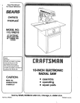
10 in. COMPOUND MITER SAW
DOUBLE INSULATED
Model No.
315.212740
A
WARNING: To reducethe risk of injury,
the user mustread and understandthe
operator'smanual beforeusing this product.
Customer
Help Une: 1-.800-932-3188
Sears, Roebuck and Co., 3333 Beverly Rd., Hoffman Estates, [L 60179 USA
Visit the Craftsman web page: www.eears.com/crsftsman
983000-551
9-04
Save this manual
for future
reference
•
Warranty............................................................................................................................................................................
2
Introduction .......................................................................................................................................................................
2
• General Safety Rules.....................................................................................................................................................
3-4
• Specific Safety Rules.....................................................................................................................................................
4-5
• Symbols.........................................................................................................................................................................
6-7
•
Electrical............................................................................................................................................................................
8
•
GLossaryof Terms..............................................................................................................................................................
9
•
Fea_ras .....................................................................................................................................................................
10-12
• Tools Needed .................................................................................................................................................................
12
•
Loose Parts ....................................................................................................................................................................
13
•
Assembly...................................................................................................................................................................
14-23
• Operation...................................................................................................................................................................
23-31
•
Adjustments...................................................................................................................................................................
•
Maintenance..............................................................................................................................................................
33-35
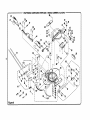
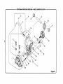
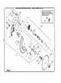
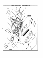
• Exploded_ew ...........................................................................................................................................................
37-45
•
PartsOrderingJServlca......................................................................................................................................
32
Back Page
ONE YEAR FULL WARRANTY ON CRAFTSMAN TOOL
If this Craftsman tool fails due to a defect in materialor workmanshipwithinoneyaar fTomthe date of purchase,
CONTACT THE NEAREST SEARS PARTS & REPAIR CENTER at 1-800-4-SV-M_:
HOME O and Searswill repair It, free of
charge. This warranty applies onlywhile this product Is in the Unltod States,
_fthis tool is used for commercLalor rentalpurposes,this warranty will apply for only ninetydays fi'onlthe date of
purchase.
This warranty givesyou specificlegal dghts, and you may also have other dghts which varyfrom state to state.
Sears, Roebuck and Co., Dept. 817WA, Hoffman Estates, IL 60179
This tool has manyfeatures for making Its use mornpleasant and enjoyable. Safety, pedormancs, and dependability
have been given top priorityin the design of this product makingit easy to maintain and operate.
_k
• 3ECURE WORK. Use clamps or a vise to hold work
when pract!cal,It's s_far than using yourhand and
freesboth handsto operate tool.
• DON'T OVERREACH. Keep proper footingand
balance at all times.
WARNING." Read and understand all inet_uot/one. Failure to follow all instruotfons listedbelow,
may resultIn etectdc shock,tlre and/or serious
personal injury.
READ ALL INSTRUCTIONS
•
MNNT/UN TOOLS WITH CARE. Keep tools sharp
and clean for better and safer performance. Follow
instructionsfor Lubricating and changingaccessories.
• DISCONNECT TOOLS. When not in use, before
servicing, or when changing attachments, blades, bits,
cutters, etc., ell too{sshould be disosnnected.
• AVOID ACCIDENTAL STAR'nNG. Be sure switch is off
when plugging in any tool.
• USE RECOMMENDED ACCESSORIES. The use of
improperaccessoriesmay dsk injury.
• KNOW YOUR POWER TOOL. Read the operator's
manual carefully.Learn the saw's applications and
{(mltations as we{{as the specific potent_{ hazards
related to this toot.
• GUARD AGAINST ELECTRICAL SHOCK BY PREVENTING BODY CONTACT WITH GROUNDED
•
•
•
•
•
SURFACES. For example, pipes, radiators, ranges,
refrigeratorenclosures.
KEEP GUARDS IN PLACE and In good workingorder.
REMOVE ADJUSTING KEYS AND WRENCHES.
Form habit of checldngto see that keys and adjusting
wrenches are removed from tool beforeturning it on.
KEEP WORK AREA CLEAN. Cluttered areas and
benches invite accidents. DO NOT leaveto_,s or
places of wood on the saw while it Is In operation.
DO NOT USE IN DANGEROUS ENVIRONMENTS.
Do r_t use Dowertools in damp or wet Iocatk_neor
expose to rain. Keep the work areawell tit.
KEEP CHILDREN AND VISITORS AWAY. A/I visitors
shou;dwear safety glasses and be kept a safe
distance from work araa. Do not let visitors contact too_
or extens'=oncord while operating.
•
•
• MAKE WORKSHOP CHILDPROOF with padlocks and
masterswitches, or by removingstarer keys.
•
• DON'T FORCE TOOL. it will do the job better and
safer at the feed rate for which it was designed.
• USE RIGHT TOOL. Don't force the tool or attachment
to do aiob it was not designedfor. Don't use it for a
purpose not intended.
• USE THE PROPER EXTENSION CORD. Make sure
your extension cord is in'goodcondition. Use only a
cord heavy enough1o carry the currentyourproduct
will draw. An undersizedcord will cause • drop in _ine
voltage resultingin loss of power and overhcating.A
wire gauge size (A.W.G.)of at least 14 Is recommended
for an extension cord 25 feet or less in length, if in
doubt, use the next heavier gauge. The smallerthe
gauge number,the heavierthe cord,
• DRESS PROPERLY, Do not wear looseclothing,
gloves, nec_as, or)ewelry.They can get caught
and draw you Into moving parts. Rubbergloves and
nonskidfooWvearare reaommendedwhen working
outdoors.Alsowear protectivehair coveting Io contain
long hair.
• ALWAYSWEARSAFETYGLASSESW|TH SIDE
SHIELDS. Everyday eyeglasseshave only Impactres'lstantlenses, they are NOT setety g;asees.
•
•
NEVER STAND ON TOOL. Serious injurycould occur
if the tool is tipped or if the cutting toot is unintentionally centacte_,
CHECK DAMAGED PARTS. Batonsfurther use of
the loci, a guard or othar _rt that is damaged should
be carefullychecked to determine that it will operate
properlyand perform its intended function.Check for
alignment of moving pads, b_ndingof moving pads,
_a
of parts, moun_ng and any other condllk_ts
that may affect its operation. A guard or other pert that
is damaged mu_t be properly repairedor repla_d by
an authorizedservicecenter to avoiddsk of personaJ
injury.
USE THE RIGHT DIRECTION OF FEED. Feed work
Into a blade or cutter against the directionof rotation of
blade or cutter only.
NEVER LEAVE TOOL RUNNING UNATTENDED.
TURN THE POWER OFF, Don't leave tool until it
comas to a complete stop.
PROTECT YOUR LUNGS. Wear a face or dust mask if
the cuffing operation Is dusty,
• PROTECT YOUR HEARING, Wear hearingprotection
during extended periodsof opera,on.
• DO HOT ABU.RECORD. Never yank cord to disconnect from receptacle. Keep cord from heat, o11,end
sharpedges.
• USE OUTDOOR EXTENSION CORDS. When tool Is
used outdoors,usa onlyextension cordswith approved groundconnection that are intended for use
outdoors and so mmked,
•
KEEP BLADES CLEAN, SHARP, AND WITH SUFRCIENT SET. Sharp blades minimizestallingand
kickback.
• BLADE COASTS AFTER BEING TURNED OFF.
•
3
NEVER USE IN AN EXPLOSIVE ATMOSPHERE.
Normal sparkingof the motor could ignite fumes.
•
•
•
•
•
•
• USE ONLY CORRECT BLADES, Do not use blades
with incorrectsize holes. Never use blade washers or
blade bottsthat ate detective or incorrect. The maximum blade capacity of your saw is 10 in. (254 mm).
• BEFORE MAKING A CUT, BE SURE ALL ADJUSTMENTS ARE SECURE.
INdPECT TOOL CORDS PERIODICALLY. if damaged,
have repairedby 8 qua_Lfied
service technician at
an authorizedservice facility.The conductorwith
Insulationhevlngan outer surfacethat Is green with
or wYchout
yellow s_pee is the equipmenL-groundin9 conductor,ff repair or replacementof the electric
cord or plug is necessaPz,do not oonnect The equipmen'_-ground'mg
conductor to a live term'inst.Repair
or replace a damaged or worn cordImmediately.Stay
constantly aware of cord {(>cationand keep ttwelt sway
from the rotatingblade.
INSPECT EXTENSION CORDS PERIODICALLY and
reOlace tf damaged.
POLARIZED PLUGS. To reduce the dsk of e[ectdc
shock, this tool has a po{adzedplug (one blade is
wider than the other). This plug will f_ in a polarized
outlet only one way. It the plug does not fit fullyin _e
out_et,reversethe plug, If it stiltdoes not fit, contact a
qusL'zfiedetect_clanto Install the proper Duller.Do not
change the plug in any way.
KEEP TOOL DRY, CLEAN, AND FREE FROM OIL
AND GREASE, A_waysuse a c_sanclothwhen c_saning. Never usebrake fluids,gasoline,petroleum-based
products, or any so(ventsto c{eantoo(.
STAY ALERT AND EXERCISE CONTROL. Watch
what you are doing and use common sense, Do not
operate too( when you aretired. Do not rush.
DO NOT USE TOOL IF SWITCH DOES NOT TURN IT
ON AND OFR Have defective switches replaced by an
authorized service center.
• BE SURE BLADE PATH IS FREE OF NAILS. Inspec_
for and removeall nailsfrom lumber before cuffing.
• NJ_fER TOUCH BLADE or othermoving parts dudng
use.
• NEVER START A TOOL WHEN ANY ROTATING COMPONENT IS IN CONTACT WITH THE WORKPIECE.
• DO NOT OPERATE A TOOL WHILE UNDER THE
INFLUENCE OF DRUGS, ALCOHOL, OR ANY
MEDIOATION.
• WHEN SERVICING use only identicel replacement
palls. Use of any other parts may create a hazard or
csuee productdema_je,
• USE ONLY RECOMMENDED ACCESSORIES ltsled
in this menus( or addendums, Use of accessories
that ere not [(sled may cause the risk of personal
Inlury, instructions for safe use of accessories are
inc(uded with the accessory,
• DOUBLE CHECK ALL SETUPS. Make sure blade is
tight and not making contact with saw or workpiece
before connecting to power supply.
BEFORE OPERATING YOUR SAW. Lock the miter
table by securelytightening the miter _ockk_vere.Lock
the saw arm (bevel _nction) by securelytighteningthe
bevel lock knot_,
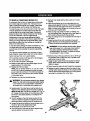
• FIRMLY CLAMP OR BOLT your miter saw to a workbench or table at approx'_nately h_p height.
• KEEP HANDS AWAY FROM CUTTING AREA. Do not
reach underneathwork or in blade cutting path with
your hands and fingers for any reason. Always turn the
power off,
• ALWAYS SUPPORT LONG WORKPIECES while cutring to minimize risk of blade pinchingand kickback.
Saw may Hip, walk or s_de while cuffing long or heavy
boards.
NEVER USE A LENGTH 8TOP ON THE FREE SCRAP
END OF A CLAMPED WORKPIECE. NEVER hold
onto or bind the free scrap end of the workpiese in any
operation.If awork clamp and length stop are used
toget*ner,they must bot_ be installedon the same Side
of the saw table to preventthe saw Jmm catchingthe
loose end and klcldngup,
• ALWAYS USE A CLAMP to secure the workplece
when possible.
• BE SURE THE BLADE CLEAR_ THE WORKPIECE.
Never startthe sew with the blade touching the
workplece. Allow motor to come up to fult speed
before start(n9 cut.
• MAKE SURE THE MITER TABLE AND SAW ARM
{BEVEL FUNCTION) ARE LOCKED IN POSITION
NEVER out more thsn one piece at a time. DO NOT
b'rACK more than one workpiece on the saw table at a
time.
NEVER PERFORM ANY OPERATION FREEHAND.
Always place the workpieco to be cu_ on the miter
table and posl_on It firmly against the fence as a bachstop, Abbeys use the fence.
4
• ALWAYS STAY ALERTI Do not allow farnliled_
(gained
ftom frequent use of your saw) to cause a careless
mistake. ALWAYS REMEMBER that a careless fraction
of a second is sl._ c_mt to Snil_-'tsm/ere Iniu_j.
• MAKE SURE THE WORK AREA HAS AMPLE LIGHTING to see the work and that no obstructionswill interfere with safe operation BEFORE performingany work
u_ng your saw.
• ALWAYS TURN OFF THE SAW beforedisconnecting
It to avoid accidental startingwhen reconnectingto
power supply.NEVER leavethe saw unattendedwhi_e
connectedto a power source.
• NEVER hand hold a wo.rl_lece that is too small to be
clamped. Keep hands clear of the cutting area.
• NEVER reach behind, under,or within three inches
of the blade and Its cutting path with your hands and
fingers for any reason.
• NEVER reach to pick up a workplace, a piece of scrap,
or anythingelse that is in or nea_'thecutting path ofthe
blade.
• AVOID AWKWARD OPERATIONS AND HAND
PORTIONS where a sudden slip could cause your
hand to move intothe blade. ALWAYS make sure you
have good balance. NEVER operate your miter saw
on the f_oor or in a crouchedposition.
• THIS TOOL shouldhave the following markings:
• NEVER stand or have any part of your body in linewith
the path of the saw blade.
• ALWAYS release the power switch and allowthe
caw blade to stop rotatingbefore raisingit out of the
workplace.
• DO NOT TURN THE MOTOR SWITCH ON AND OFF
RAPIDLY. This could cause the saw blade to loosen
and could create a hazard. Shouldthis ever occur,
stand dear and allow the saw blade tocome to a
complete stop. Disconnect your saw flora the power
supply and sacursiy ret_ghtenthe blade bolt.
• IF ANY PART OF THIS MITER SAW IS MISSING or
shou[d break, bend, or fail in anyway, or shouldany
dsctdcaJ component fsil to perform properly,shut off
the power switch, removethe miter saw plug from the
power source and have damaged, missing, or failed
parts replaced before resumingoperation.
,_
a)
To)
c)
d)
s)
f)
Wear eye protection,
Keep hands out of path of saw blade
Do not operate saw without guards in place.
Do not perform any operation freehand,
Never reach aroundsaw blade.
Turnoff tool and walt for saw blade to stop before
moving workp(eceor changing settings,
g) Disconnect power (or unplug too( as applicable)
before changing blade or servicing.
h) No iced speed,
• ALWAYS carry the too[ onlyby the carryinghandle,
• AVOID direct eye exposurewhen using the laserguide.
• SAVE THESE INSTRUCTIONS. Refer to them
fi'eduent_yand use to instruct other users.If you Loan
someone this tool, foan them these Instructions alsO.
WARNING: Some dust created by power sanding, sawing, grinding,drilling,end other construction activities
contains chemlcels known to cause cancer, birth defects or other reproductiveharm. Some examples of these
chemic,areare:
•
(sad from lead-based paints,
•
crystallinesilicafrom bricksand cement and othermasonry products,and
•
arsenic and chromiumfrom chemically-treatedlumber.
Your risk from these exposure(;redes, depending on how often you do this type of work. To reduce your exposure
to these chemicals:work in a well ventilated area, and work with approved cafety equipment, such as those dust
masks that are specially designed to filter out microscopicpa_cies.
5
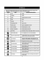
Someofthe followingsymbolsmay be used on this too]. Please study them and learntheir meaning. Proper
Interpretstfonof these symbolswill allow you to operate the tool better and safer.
SYMBOL
NAME
DESIGNATIONIEXPLANATI ON
v
Vc_te
Voltage
A
Ampuls
C_rre_t
Hz
Hertz
Frequency(cycles per second)
W
Watt
Power
Minutes
Time
Alternating Current
Type o'tcurrent
DirectCurrent
Type or a characteristicof current
no
No t-oad Speed
Rotational speed, at no load
[]
Class li Construction
Doubie-insuisteqconstruction
.../min
Per MinUte
Revolutions,strokes,surface speed, orbits etc., per minute
®
Wet ConditionsAlert
Do not expose to rain or use in damp locations.
Read The Operetor'sManual
To reduce the dsk of injury,user must read and understand
operator'smanuat before usingthis product.
Eye Protection
Always wear safety gogglesor safety g_asseswith side
shields and a full face shieldwhen operatingthis product.
Safety Alan
Preeau_ionsthat involve your safety.
hLot-_nds Symbol
Faltureto keep your handsaway from the blade will result In
sedous personal Injury.
No Hands Symbol
Failureto keep your handsaway from the bladewill resultin
serious personal injury.
min
,_,
O
&
®
®
@
®
m
No Hands Symbol
Failureto keep your handsaway from the bladewill resultin
serious persona{injury.
No Hands Symbol
Failureto keep your hands away from the blade will resultin
seriouspersonal Injury.
Hot Surface
TOreduce the risk ot injuryor damage, avoid contact with
any hot surface.
6
The fo(Iow[ngsignal words and meaningsare intended to explain the levelsof risk associatedwith this
product.
SYMBOL
SIGNAL
MEANING
A
DANGER:
Indicates an Immlnentty hazardous situation,which, If not avoided, wtl)
resultin death or serious injury.
A
WARNING:
|ndicates a potentially hazardous situation, which, if not avoided, could
result in death or serious injury.
,_
CAUTION:
Indicate_ a polentially hazardous eftuslJon,which, if nol avoided, may
resultIn minor or moderate Inlury.
CAUTION:
(Without Safety Alert Symbol) Indicates a situation that may result in
property damage.
SERVICE
A
Servicing requires extreme care and knowledgeand
should be performedonly by a qualified servicetechnician. For servicewe suggestyou returnthe productto
your nearest AUTHORIZED 8ERVIGE GENTER for repair.
When servicing, usa only Identicalreplacement parts.
WARNING: To avoid serious personalInjury,
do not attempt to use this productuntil you read
thoroughlyand understandcomplete)ythe
operator'smanual Save this opemfer's manual
end reviewfrequently for continuing safe operation and instructingotherswho may use this
product.
,&WARNING:
The operationof any powertoo( can resultin foreignobjects beingthrown intoyour eyes,which can
O
safely glasses wffh side shieldsand a full face shieldwhen needed. We reGommendWide Vision Safety
resultIn
eyeeyeglasses
damage. Beforebeginning
powertool
opera_lon,alwayswear
gogglesor
Mask forsevere
use over
or standard safety
glasseswith
side shields.Alwayssafety
use eye
protection
whioh is marked to cemply with ANSi Z87.1.
SAVE THESE INSTRUCTIONS
DOUBLE INSULATION
Doubts insulationIs a concept In safety in electric power
tools, which eliminatesthe need for the usualthree-wire
groundedpower cord. All exposed metal parts are
Isolated from the internalmetal motor componentswith
protecting insulation.Double insulatedtools do not need
to be grounded.
A
EXTENSION
CORDS
When usinga powertool at a considerablecllstancafrom
s powersource, be sure to use an extensioncord that has
the capac'rtyto handle the currentthe tool wilt drew. An
undersizedcord will cause a drop in linevoltage, resulting
in overheatingand loss of power. Use the chart to determine the minimum wire size requiredIn an extensioncord.
Only roundjacketed cords listedby Underwritsr'sLaboratories (U_ sl_utd be used.
WARNING: "the double insotated system is
Intendedto protect the user from shock resulting
fToma break in the tool's internalinsulation, Observe
a(! normal safety precautionsto avoidafec_caf
shock.
When workln 9 outdoorswith e Icon, use an ext_sk_n cord
_thB.t
is _e_'_gne_tot ouL_'_deusa. _'hie type ot cord is _eeignated w_th=WA" on the cord's )acket.
Before using any sxte_don cord, _nspect it for loose or exposedwires and cut or worn insulation.
NOTE: Servicingof a tool with double Insulationrequires
extreme care and knowiedgeof the system and should
be performed onlyby a qua.fled service tenhnlclan.For
service,we suggestyou return the tool to your nearest
authorized service center for repair.Always use original
factory replacement pafcswhen servicing.
ELECTRICAL
0-2.0
2*1-3.4
Cord Length
5.1-7.0
7.1-12.0
12.1-16.0
25'
16
16
16
16
14
14
50'
16
16
16
14
14
12
100'
18
16
14
12
10
--
CONNECTION
This tool has;a precision-buntelectric motor. It shouldbe
connected to e power supply that It 120 voltS, 60 Hz,
AC only {normal houSehold current). Do not operate
this tool on direct current (DC). A substantialvoltage drop
wlrrcause a Jossof power and the motorwill overheat, rf
yourtoot does not operate when plugged intoan outlet,
double-check the Dowersupply.
3.0-5.0
WInDSize (A.W.G.)
"Used on _ ga_,_e- 20 amp_t:_
NO1rF_.:
AWO- Arnedr,_m
W'_ Gauge
8
A
WARNING: Keep the extension cord clear or the
workingarea. Positionthe cord so that it willnot get
caught on lumber,tools or other obstructionswhile
you are workingwith a power tool Failureto do so
can resultIn ssdous persona!injury.
A
WARNING: Check exten._on cords before each
use. If damaged replace immediately.Never use tool
with a damaged cord since touching the _amaged
area could cause elec_cal shock resultingin serious
Injury.
Anti-Kickback
Pawls(radialarmandtablesaws)
Adevisewhich,whenproperty
instatedandmaintained,
Is designedto stop the workplace from being kicked back
toward the front of the saw duringa rippingoperation.
Arbor
The shaft on which a blade or cutting tool is mounted.
Bevel Cut
A cut,rig operation made wit'nthe blade at any angle
other than 90* to the table surface.
Chamler
A cut removinga wedge from a black so the end (or part
of the end) is angled rather than at 90..
Compound Cut
A cross cut made with both a miter end a bevel angle.
Crosscut
A cut_ng or shaping opera, on made across the grain or
the width of the workplene.
Cutter Head (planers andjothters)
A rots_ng plece of adjustableblades. "Thecutter heed
removes material from the workpiace.
Dado Cut
A non-throughcut which produces a squara-s_dednotch
or troughIn the workplece (requiresa speclalblade).
Featherboard
A device used to help controlthe wod_ptaceby gu)dlngit
sacuretyagainst the table o?fence during any dpplng
operation.
FPM or SPM
Feet per rnlnute(or strokes per minute), used in reference
to blade movement.
Freehand
Performinga out without the workplace being guided by a
fence, miter gauge, or other aids.
Gum
A s_ck'7,sap-based residue from wood products.
Heel
Altgnmentof the blade to the fence.
Karl
The material removed by the blade in a through cut or the
slot produced by the blade In a non-throughor partial cut.
Kickback
A hazard that can occurwhen the blade b_ndsor stalls,
throwingthe workplace back toward operator.
Leading End
The end of the workplace pushed intothe tool first.
Miter Cut
A cutting spars'donmade w_n the workpiece at any angle
to the blade otherthen 90 °.
Non-Through Guts
Any cuing operationwhere the blade does not extend
completely through the thicknessof the workpiace.
Push Blooke and Push Stloks
Devtcesused to feed the workplace throughthe saw
blade during cutting operations.A push stick (not a push
block)should be used for narrow dpping operations.
These aids h_,p keep the operator's hands w_l away from
the blede.
Pilot Hole (drill presses)
A small hera drilled In a workp_ce that sawes as a guide
for dr_(lfnglarge holesaccurately.
Resaw
A cuing op_atton to reducethe thickness of the workpiece to make thinner pieces.
Resin
A sticky,se.p-t:_sed substancethat has hardened.
Revolutions Per Minute (RPM)
The number of _rns completed by a spinningobjac_in
one minute.
Ripping or Rip Cut
A cuing operation alongthe leng'ih ol the workplace.
Rkdng Knife [table saws)
Also known as e spreader or splitter.A metal piece, slightty thinner than the saw b_ade,which h_ps keep the _erf
open and also helps to prevent kickback.
Saw Blade Path
The area over,under,behind, or in frontof the blade. As
it applies to the workpiece, that area which will be or has
been cut by the blade.
Set
The distancethat the tip of the saw blade tooth is bent (or
set)
outwardfromthe face of theblade.
Snipe (planers]
De0rsssionmade at either end of a workpiece by cutler
bladeswhen the workpiace is not properly supported.
Throw-Back
The throwing back of a workplace usuallycaused by the
workpiece being dropped intothe blade or being placed
InadvertentlyIn contact with the blade.
Through Sawing
Any cut'_ng opera, on where the blade extends completely
throughthe thickness of the workplace,
Workplace or Material
The item on which the operation is being done.
WoltCmble
Sur_ce wh_re the workplace restswhi(eperfom_ing
a
cutting,
drilting,
planing,
orsandingoperation.
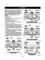
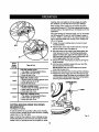
PRODUCT
SPECIFICATIONS
Blade Diameter ............................
B_de Arbor ...............................
10 in.
5/8 in.
Cutting Capacitywtth Miterat0°/Bevel 0_:
Maximum nominal[umbersizes:.................... 2 x 6, 4 x 4
No Load Speed .........................
5,000/min.
Input ................
120 V, 60 Hz, AC Only.15 Amps
Net Weight ..............................
36.5 tbs.
Cuttlng Capacity with Miter at 45°/Beve! 0°:
Maximum nominallumber sizes:............................. 2 x 4
Cutting Capacity WithMiter at 0°iBeval 45°:
Maximum nominal lumber sizes:............................. 2 x 6
Cutting Capac'l_ with _i_er at 45"/Beve_45_:
Maximum nominal[umberalzes: ............................. 2 x 4
HANDLE
UPPERBLADE
GUARD
• SWITCH
TRIGGER
SELF-RETRACTING
LOWERBLADE
GUARD
DUST GUIDE
SLIDINGMITER
FENCE
DUST BAG
"NO HANDS"
BEVELSCALE
CROWNMOLDING
STOP
"NOHANDS"
BOUNDARY
LINE
ZEROCLEARANCE
THROATPLATE
BEVELLOCKKNOB
Mm_ SCALE
FENCESCREW
BLADEWRENCH
STORAGE
MITER LOCK
HANDLE
MITERLOCK
PLATE
MITER
TABLE
BASE
POSITIVE
STOP
BLOCK
TABLE
EXTENSION
STO_S)
ROLLER
SUPPORT
WORKCLAMP
Fig. I
10
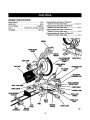
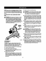
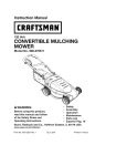
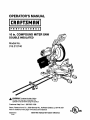
KNOW YOUR
See Figure 1.
COMPOUND
MITER
SAW
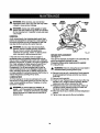
SPINDLE LOCK Bu'rroN
See Figure3.
Before attempting to use this product, familiarizeyourself
w_ ail operating features and safety rules.
A spindlelock button has been providedfor lockingthe
spindlewhich keeps the blade In your saw from rotating.
Depressand hold the lock button while instaging,changing, or removingblade.
15 AMP MOTOR
Your sew has a powerful15 amp belt-driven motor with
sufficientpower to handle tough cutting lobs. It Is made
w;th airball bsedngs,and has externallyaecesaibre brushes for ease of servicing.
10 in, BLADE
A 10 in. carbide-Upped saw blade is included with your
compound miter sew. It will cut materialsup to 4 in. thick
or 6 In. wide, depending upon the angle at which the cut
is being made.
SWITCH
mlGGER
CARRYING
HANDLE
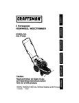
See Figure 2.
For conveniencewhen carr_ng or transportingyour
miter saw from one place to another,a carryinghandte
has been provlded on top of the saw arm. To transport,
turn off and unplug your sew, then lower the sew arm and
lock it in the down position.Lock saw arm by pushingthe
lock pin to the left.
SPINDLE
LOCKBUTi'ON
Fig. 3
CARRYING
HANDL£
SAW
ARM
SWITCH TRIGGER
See Figure 4.
LOCKPiN
LOCK
To preventunauthorizeduse of your compound miter saw,
we suggestthat you disconnectIt from the power supply
and lock the switch in the off position.To took the switch,
installa padlock (not included)throughthe hole in the
switch trigger,A lock with a tong shackteup to 9/32 In.
diameter may be used. When the lock is insta(iedand
locked, the switch Is Inoperable.Store the padlock key In
another location.
DEVEL
KNOB
MITERLOCK
HANOLE
SAWARM
LOCKED
IN GOWNPOSITION
Fig. 2
MITER LOCK
See Rgure 2.
HANDLE
The miter lock handle securelyrocks your saw at desired
miter angles.
Fig. 4
11
LASERTRACTM
LASER GUIDE
For more accurate cuts, a LasarTmcTM laser guide Is
included with your miter saw. When used properly,the
laser guide makes accurate, precisioncutting simpleand
easy.
SLIDING
MITER
FENCE
Posn'IVE
STOPS ON MITER TABLE
Positivestops have been provided at 0 °, 15°, 22-1/2 °,
31.62 °, and 45° on both the left and right side of the miter
table.
Slide the miter fences by tooseningthe fence screws.
Once the dealredposition of the miter fence Is determined, retightsnthe fence screws to secure the sliding
fence.
BEVEL LOCK KNOB
The bevel lock knob securelylocks your compound miter
saw at desired bevel angles. A positive stop adiustment
screw has been provided on each srde of the saw arm.
These adjustment screwsare for making fine adjustments
at O"and 45".
SELF-RETRACTING
LOWER BLADE GUARD
The lower blade guard is made of shook-resistant,seethrough plasticthat providesprotectionfl'omeach side
of the blade. It retracts over the upper blade guard as the
saw isloweredintotheworkplsce,
Hold the workpiesa securely against the mRer fence when
making all cuts. The stiding feature atlows both fences (left
and right) to be moved when making bevel or compound
CLIts,
ROLLER SUPPORT
WI_ the miler supportInstalled, the workplace will glide
smoothlyand levellyover the table extensions.
ELECTRIC
BRAKE
An electdo brake has been provided to quioklystop blade
rotation after the switch is reteaead.
CROWN MOLDING
STOP
The crown molding stop makes positioningcrownmolding
verticallyagainstthe fence easier.
The followingtools (not Included} are needed for checking adlus_ents of your saw or for Installing the blade:
COMBINATION
WRENCH(2)
10 ram,14me
COMSINA7"/ON
S01/ARE
FRAMINGSQUARE
PHILLIPSSCREWDRIVER
12
Fig. 5
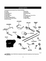
The follow'_ngi_:emsare Lncludedw|th your CompoundMiter Saw;
•
•
Dust Bag
Dust Guide
• WorkClamp
• Blade Wrench
• Outer BladeWasher
• Bolt
• Table Extensions(2)
• Clamp Breaker
• CLampBracket Bolt
• RoLLer
Support
• LeveLerwith attached Wing Nut
• Stop Block wlth Wing Bolt attached
• Miter Lock Handle
• Hex Key (3), 4 mm, 5 mm, and 8 mm
• Crown Molding Stop
• Laser Glasses
• Operator's Manual
LASERGLASSES
WORKCLAMP
I_11ERLOCK
BLADEWRENCH
ROLLER
SUPPORT
4 ram, S ram,8 mm
HE)CKEYiS)
°°,T,,o
=oy .
TABLEEXTENSION
_
CROWNMOLDING
STOP
BRACKET
_
\
BOLT
OUTER
8LAOE
WASHER
WINGSCREW
Fig. 6
_i
WARNING- The use of ettechments or scsessodes not listedmight be hazardousend c_uk_oause sedous
personalInjury.
13
UNPACKING
_lb WARNING: Do not attempt to modify this tool
or create accessories not recommendedfor use
with this tool. Any such alterationor modificationIs
misuse and could resultin a hazardouscondition
feeding to possibleseriouspersonal injury.
This product requires assembly.
•
Carefullylift saw fTomthe carton by the carrying handle
and the saw base, and place it on a lard work surface.
NOTE: Th_ssaw is heeW.'To avoid back I_lury, _.w_th
your legs, not your back, and get help when needed.
•
Thissaw has been shipped with the saw arm secured
in the down position.To release the saw arm, push
down on the top of the saw arm, cutthe tie-wrap, and
puttout or the look pin,
•
Uft the saw arm by the handle. Hand pressureshould
remain on the saw arm to prevent sudden rise upon
mtesae ol _hetie wrap.
WARNING: Do not connect to powersupply until
assembly is complete. Failureto complycouJdresult
_naccJdantalstarting and poss]b_asarfous personal
iniu_
MOUNTING
HOLES
See Figure 7.
• Inspect the tool carefullyto make sure no breakage or
damage occurreddudng shipping.
• Do not discard the packing material un_JJ
you have
carsfultyinspected and set'=sfectofi_yoperated the tool.
_
• The saw is factory set for accurate cutting. After
assarnbllngit, check for accuracy, if shippinghas
influencedthe settings, refer to specific procedures
explained in this manual."
The compound miter saw shouldbe permanentlymounted to a firm supportingsurface such as a workbench.
Four bolt holes have been provided in the saw base fOr
this puq_ose.Each of the four mounting holes should be
bolted securelyusing 3/8 In. machine bolts, lock washers,
an_ hex nuts (not included). Bo_tsshouldbe of su_clent
length to accommodate the saw base, [ockwashers, hex
nuts, and the thicknessof the workbench.
• If any parts are damaged or missing, please call
1-800-932-3188 for assistance.
WARNING: (f any parts are m[sslng, do not operate
this tool untll the missing parts are replaced. Faflbre
to do so could result in possible sedouspersonal
injury.
WARNING: Always make sure the compound mltsr
saw is securelymounted to e workbench or an approvedworkstand. Failureto heed this warning can
recuit
insadousperso_L inlu
w.
Tightec airfour bolts securely.
The hole pattern for mountingto a workbench is shownin
figure 8. Carefullycheck the workbench attar mounting to
make sure that no movement can occur during use. If any
Upping,sliding,or walking is noted, securethe workbench
to the floor before operating.
TRACEHOLES
ATTHESELOCATIONS
FOR
HOLEPATIF1ERN
TRACEHOLES
A"T"tHESE
LOCATIONS
FOR
HOLEPA'TrERN
IAOUNTIH_i
SURFACE
BASE
Fig. 7
14
Asmantfoned
previously,
thesawhasbeenfactory
assembledand adiusted.
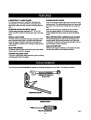
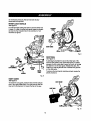
MITER LOCK HANDLE
See Figure 8,
Cut the tie-wraps holdingthe saw arm and the miter lock
in place, To install the miter lock handle, place the threaded stud into the threaded hole in the controlarm, Turn
clockwiseto tighten,
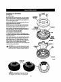
EXHAUST
PORT
\
Fig. 9
DUST BAG
See FJgure10.
TO
TIGHTEN
A dust bag ht providedfor use on this miter saw. tt fits
over the dustguideon the up_r bladeg_l.
To _nst_ll,
squeezethetwo metalclips
toopen themouth ofthebag
and slide
Iton tothedustguide.Releasethecllps.
The
metalrthginthe"gagshouldlockinbetweenthegrooves
on the dust guide.
CONmOL
ARM
TO
LOOSEN
MnZX
TABLE
To remove the dust bag for emptying, simplyreverse the
above procedure.
Fig. 8
DUST GUIDE
See Figure 9,
DUSTSUIDE
To Installthe dust guide, piece the end over the exhaust
port in the upper blade guard. Turn the guide so that the
open end Is facing down or toward the rear of the saw.
DUSTBAg
\
Fig. 10
15
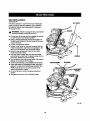
TABLE EXTENSIONS
BRACKET
SUPPORT
See Figures 11 - 12,
Table extensionscan be instaflad in either the left or the
rfghtsfdeof the base.
To install:
i Insertthe ends of the table extensionsinto the holesin
the side of the bass and adjust the extensionsto the
desired length.
• Secure extensionsinplace by positioningthe clamp
bracket under the extensionbeneath the base. Orient
the clamp bracket as shown in figure 12.
• Using the clamp bracket bolt, securethe clamp
bracket in place.
NOTE: The clamp bracket bolt threadsthrough the
c_ampbrac_,et and tightens againstbracket supporton
bottom of base, securingc_p bracket ag_nst _ble
extensions.
CLAMP
BRACKET
ROLLER SUPPORT
See Figure 13.
• Turn the rottersupport upside down.
CLAMP
BRACKET
SCREW
•
Spin the wing nut on the levelerclockwiseuntilthe
wing nut Is positionedIn the middle of the threads,
• Screw the leveler into the center brace of the roller
support.
SAW_'1E'WEO
FROM6Ol"rOM
Fig. 12
• Turnthe rollersupport upright.
• W_ththe table extensionssecured in the saw's base.
slide the roller support onto the extensions.
•
BASE
WINQNUT
Tightenthe wing nut on the back of the rollersupport
secudng it to the table extensions.
ROLLERSUPPORT
TABLEEXTENSION
• The levelermust sit firmlyon the surfacethe saw is
mounted to. Adjust the leveler up or down as needed.
• Once the leveleris in the proper position,turn the lever
wing nut until the wing nut is t_ghtagainstthe center
brace.
WING NUT
TABLE
EXTENSION
Fig. 13
TABLE
EXTENSION
m
SAWBASE
Fig. 11
_6
_lb
WARNING: When using the work clamp with the
stop block, install the clamp on the same side as the
stop block. This will elimlnatsthe possibilityof _rapping the workpisce, resultingin the saw b]ade and
work,oiecekicking up. Failureto heed this warning
can result in serious persona]injury,
STOP BLOCK
See Figure 14.
STQP
BLOCK
The stop block is usefulas a stop for making repstlt_ve
cuts to the same length. It can be installedon either side
of the saw base:
• Slide the stop block on the table extension,
• Adjust the stop block the desired distancefrom the
blade for the out to be made.
TABLE
EXTENSION
• Tighten Smallwing screw to sacum the stop blockto
the table extension.
• Make a test cut in scrap matariaI and measure the
length of the workplace,
• Make any necessary adjus_ents.
MITER
SAWBASE
WORK CLAMP ASSEMBLY
See Figure 15.
Fig. 14
The work clamp provides greater controlby clampingthe
workpisce to the fence or the saw table. It also prevents
the workpisce from creeping toward the saw blade. Thisis
very helpfuiwhen cutting compound miters.
Depending on the cutting operationand the size of the
workpieee, it may be neces,_ry to use a C-clamp instead
of the work clamp to secure the workpisce pdor to making
the cut.
A
WARNING: in some operations, the work clamp
assembly may interferewlth the operation of the
blade guard assembly. Always make sure there is no
interferencewith the blade guard priorto beginning
shy cutt_r_
9 operationto reduce the risk of serious
personalInjury,
To install
thewod_clamp:
• Piecetheshaftofthework clamp ineither
holeon ths
saw table base.
•
Rotate the knob on the work clamp to move it in or out
as needed or press the Rulckrelease laver for faster
position'mg,
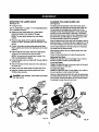
TO INSTALL BLADE
See Figures 16.18.
WARNING:
A 10 in. blade Ls the rr_dmum blade
capacity of the saw. Never use a blade that is too thick
to allow outer blade washer to engage with the flats
on the spindle. Larger blades will come in contact with
the blade guards, wh'_e thicker blades w'lll prevent the
blade screw from securing the blade on the spindle.
Either of these situattons could result In a serious
accidentand can cauee seriouspersonal_njury.
BASE
t7
WORK
cLAMP
Fig. 15
• Unplugthesew,
LOWERBLADE
GUARD8P,ACI(ET
• Loosen phillipsscrew on the blade bolt cover until
b_de bolt cover can be raised.
• Gently raise the lower blade guard bracket, releasing
tower blade guard _rom notch so that lower blade
guard and blade boRcover can be rotated up and back
to expose the blade bolt.
• Depress the spindlelock button and rotate the blade
boil untO{the spindle (coke.
•
Using the blade wrench provided, loosenand remove
the blade bdit,
NOTE: The b(ede bolt has left hand threads. Turn blade
bolt clockwiseto loosen.
Fig, 16
• Remove the laser
guide or outer blade washer, no not
remove _nnerblade washer.
• Wipe a drop of oll onto Inner blade washer and outer
b(ade washer where they contact the b(ede.
PHILLIPS
SCIUEW
WARNING: if inner b_de washer has been
removed, mplaca it beforeplacing blade on
spindle, Failureto do so could cause an accident
since blade will not tighten property.
LOWER
GUARD
• Fit saw blade inside lower blade guard and onto
spindle. The blade teeth point downward at the fTont
O1"
saw as shown infigure 16.
_l
TO
LOOSEN
CALITIONt A_wayslnat_l[ the I_ade with the blade
teeth and the arrow printedon the side of the blade
pointingdown at the front of the saw. The direction
of blade rotationIs also stamped with an arrow on
the upper blade guard.
TO
TIGHTEN
BLADE
BOLT
•
Replace the [aserguide or outer blade washer (see instructionson thefdiiowingpage). "thedoub_e=D" fiats
align with the fiats on the spindle.
• Depress spindle lock button and replace blade bolt.
NOTE: The blade bolt has left hand threads. Turn blade
boil count_mlockwlseto lighten.
INNERBLADE
WASHERWITH
O_U6LE'ir FlATS
Fig. 17
• lighten blade bolt securely.
•
Replace the lower blade guard and blade boil cover.
•
Refightanthe phillipsscrew eecudng the blade bolt
cover.
_1
CAUTION: Make sure the spindlek>ckbutton is not
engaged before reconnectingsaw to power source,
Never engage spindle]ock button when blade is
rotating,
SPINDLE
LOCI[
DUll'ON
Fig. 18
tS
MOUNTING
THE LASER
See Figure 19.
GUIDE
ALIGNING THE LASER GUIDE
See Figure20.
• Unplug file saw.
The laser guide will generate a red ceiored 1]neon the
work surface when the blade is spinningabove 500 rpm,
The red laser linewill appear as a broken lineon the
workplace when the blade assembly is In the uppermost
positionand the motor switch is activated, This broken
linewfll let you see your mark and yourlaser guide line at
the same time, and will assist you In liningup your mad(
for more accurate cuffing of the workplace.
See "To Install Blade" on page 17 in the Asaernb/ysestion
of this operator's manual.
• Make sure inner blade washer is in place before
pos_onlng b{adeon the sp_d(e o_the saw.
NOTE; The laser guide replaces the outer blade
washer.
• Place the laser guide ontothe spindle, aligningthe
double "0' gets In the tasar guide w_ the fta_son the
spind{e.
• Positionfiat surface of laser guide against the blade.
Warning labels are visible when laser guide is mounted
pmpedy.
•
AJignthe laser line and your mad( with the blade at the up*
permost position.Once both lines are tn a(Ignment,do not
move the workplace until after you have finishedcuffing.
As the blade asaembly is lowered toward the workplace,
the broken (Ins wll( become solid,
Make several practice outs on differentstylesand thickness of material.
Depress spindlelock button and secure laser guide
using onlythe special hex key bolt provided.
NOTE: The hex key bolt has left hand threads. Turn
bolt counterclockwiseto tighten.
Using the blade wrench provided with the saw, tighten
bolt securely,
•
•
Remove the blade wrench and store it In a safe place
for future usa.
•
Replace the lower blade guard end blade bolt cover.
•
Rstlghten phillipsscrew sscudng blade bolt cover,
Tightenscrew secursiy.
A
LINE
Fo{iowthe directionsbelow forusingthe laser guide.
Remo_l
Your Mark:
Positionthe (seerfine near the left edge of your mark on
the work surface In order to remove the mad(.
To Cut Your Mark:
Positionthe lasar line near or over your mark on the work
surface In order to cut the mark.
To Lsave Yore Mark:
Positionthe laser line near the tightedge of your mark on
the work surface in order to leave the mark.
After you have become familiarwith usingthe laser gLdde,
you wlJJbe able to remove, cut, or leave your mark on the
wor_ surface. Practice wtll t_oh _o_ _he co,act posi_on
for aligningthe laser linewith your mark.
DANGER: Laser radiation,Avoid directeye contact
with light source.
BLADE
LASER
GUIDE
BOLT
SPINDLE
BROKEN
REDLINE
INNER
WASHER
WRENCH
Fig. 19
Fig. 20
19
NOTE:Manyofthe Illustrationsin this manual show only
FRAMING
SQUARE
portions of the compound miter saw. This is intentionalso
that we can ctsadyshow points being made in the
Illustrations,Never operate your saw wlUtourlaD guards
securely in place and in good operating condition.
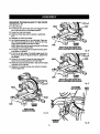
SQUARING
THE MITER
FENCE
See Figures21 - 24.
FENCE
MITERTABLE
TABLE TO THE
• Unplug the saw.
• Push down on the saw arm anti pull out the lock pin'co
release the saw arm,
• R_sa saw arm to its full raised position.
• Loosen the miter lock handle,
•
THROATPLATE
VIEWOFMITERTABLE
NOTSQUARE
WITH
FENCE,ADJUSTMENTS
AREREQUIRED
Rotate the re{tar tab(e until the pointer is posftioned
atO'.
Fig. 22
• Rat(ghtanthe miter look handle.
• Lay a fi-am[ngsquare fiat on the miter table. Piece one
leg of the squareagainst the fence. Place the other
leg ot the squarebeside the throat plate in the miter
tabte. The edge of the square and the stot in the throat
plate In the miter table shou(dbe parafle(as shown in
figure 21,
• If the edge of the framing square and the throat plate
in the miter tabte are not parallel as shown in figures22
and 23, adjustments are needed.
• Usingthe 6 mm hex key, loosen the socket head
screwssecuringthe fence, Adjustthe fence te_ or right
unlitthe framing squareand throat plate are parallel.
• Retfghtenthe screws securely and recheck the fenceto-tabre alignment before reinstallingthe slidingmiter
fence.
FENCE
/
MI ,..E
FENCE
FQuRAMIARNEG
/
MITERTABLE
VIEWOFMITERTABLENOTSQUARE
WITH
FENCE,ADJUS'iMEXTS
AREREQUIRED
Fig. 23
SOCKET
HEAD
SCREW(S)
M.RERL,02
K...---'_
J_
HANDLE _'_
SOCKET
HEAl)
SCREW(S)
THROATPLATE
'"""'_""=
VIEWOFMITERTABLESQUARE
WITHFENCE
CORRECTLY
AN&/STED
Fig. 21
Flg. 24
20
SQUARINGTHE SAWBLADETO THEFENCE
See Figures25 - 28.
FENCE
• Unplug the saw.
• Pullthe saw arm all the way down and engagethe lock
pin to ho_dthe saw arm in transport position.
• Loosenthe miter took handle.
•
Rotate the miter table until the pointeris positioned
at0".
•
•
Retightenthe miter (ock handle.
Lay a framing square flat on the miter table. P(ace one
leg of the squareagainst the fence. Slide the other leg
ol the square against the fiat part of blade.
NOTE: Make sure that the square contacts the fiat part
of _s blade, not the b_adeteeth.
• The edge of the square end the blade shouldbe parallel as shownin figure 25.
• If the frontor back edge of the blade angles away from
the square as shown in figures 26 and 27, adjustments
are needed.
FRAMINQ
SQUARE
BASE
VIEWOFBLAOENOTSQUARE
WITH
FENCE,AD-aQSTMENT_
_'_EREQUIRED
Fig, 26
FENCE
• Using a 8 mm wrench, loosenthe hex screwsthat
secure the mountingbracket to the miter table.
• Rotate the mounting bracket left or right untilthe blade
is parallelwi_ the square.
• Retightenthe screws secure(yand recheck the bladeto-fence alignment.
FRAMING
SQUARE
BASE
V)EWOFELARENOTSQUARE
WITH
FENCE,ADJUSTMENTS
AREREQUIRED
Fig. 27
9 mrn$QCKL_'
HEAD
SCREW(S)
FENCE
MITER
TABLE
VIEWOFBLARE
SQUARE
WiTHFENCE
Rg. 25
MOUNTING'
BRACKET
21
Fig.28
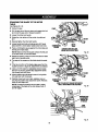
SQUARINGTHE BLADETO THE MITER
TABLE
See Figures29 - 32.
•
Unplug the saw,
FENCE
•
Pullthe saw arm all the way down and engage the lock
pin to hold the saw arm In transport position.
• Loosen the miter lock handle.
•
Rotate the miter table untilthe pointeris positioned
atO'.
• BLADE
• Securelytighten the miter lock handle.
II Loosen bevel lock knob and set saw arm at 0"bevel
(blade set 90"to miter table). 33ghtenbevel lock knob.
•
MITER
COMG[NATION
TABLE
SQUARE
CORRECT
VIEWOFBLADE
SOUABE
WITHMITERTA6lE
Place a combinationsquare againstthe miter table and
the fiat part of saw blade.
NOTE: Make sure that the square contacts the fiat part
o_the saw blade, not the blade 1seth,
•
Rg, 29
Rotate the blade by hand and check the blade-to-table
alignmentat several points.
• The edge of the square and the blade shouldbe parallel.
FENCE
• ff the top or bosom of the blade anglesaway from the
square as shown In figure 30, adjustmentsare needed.
•
Usinga 10 mm wrench or adjustable wrench, loosen
the lock nut secudng positivestop adjustment screw.
/_so _oosenbeve_lock knob.
• Adjust positive stop adjustmentscrew to bdng blade
into a(ignmentwiff_(he square.
•
MITER
COMB_ATION
TABLE
SQUARE
VIEWOFBLABENOTSQUARE
WITHMITER
TABLE,ABJUSIMENTS
AREREQUIRED
Ratlghtenbevel lock knob, Next, retightenlock nut
securingthe positive stop adjustment screw. Recheck
bla_a-to-t_bie elignmertt.
NOTE:The above procedure can be used to check
squareness of the blade to the miter table at both 0"
and 45"angles.
Fig, 30
\
POSI"FNE
STOP
ADJUSTMENT
rFOR
O°ANGLES
LOCK
Fig. 31
22
Thissawhasthree scale indicators,two on the bevel
scale and one on the miter scale. After squadngadjustments have been made, it may be necessary to loosen the
Indicator screws and reset them to zero.
FENCE
• BLADE
COMBINATION
SQUARE
MnER
TABLE
VIEWOFBLADENOTSQUARE
WITHMITER
TAm.E,ADJUSTMENTS
AREREQUIRED
Fig. 32
APPLICATIONS
This product has been designed onlyfor the purposes
_sted _,ow;
_1= WARNING: Do not allow famlllarltywlth tools to
make you careless. Remember that e careless frection of a second is sufScient to inflict severe in)ury.
,_
_,
• Crosscutting wood and plastic
• Crosscuttb_gmiters, joints,etc. for picture frames
moldings,door casings, and fine joinery
• Beret c_ttin9 and compound cu_n 9
WARNING: Ahvayswear safety goggle or safety
glasses with side shieldswhen operating tools. Failure to do so could resultIn oblects being thrown Into
your eyes resultingin possibleserious injury.
NOTE. The blade provided is fine for most wood cutting
operations,but for fine joinerycuts or cuttingplastic, use
one of the acoesso_ blades availabk_from your nearest
Sears retail store.
WARNING: Do not usa any attachments or accessories not recommended by the manufacturer of
this tool The use of attachments or accessoriesnot
recommendedcan result in serious personalinjury.
A
CAUTION: Do not start the compound miter saw
wfthout checkingfor interferencebetween tile bIade
and the throat plate. Damage could resultto the
blade if it strikesthe throat plate dudng operation of
the saw.
23
WARNfNG: Beforestarting any cutting operation,
clamp or bolt the compound miter saw to a workbench. Never operate the miter saw on the floor or in
a crouchedposition.Fallursto heed this warning can
resultin serious personalinjury.
NOTE:Always check for Interferencebetween the blade
• Tighten the miter lock handle securely.
and the sliding miter fence BEFORE attempting to make
a cut. Some compound miter cuts requirethe slidingmiter
fence to be moved or completelyremoved before making
the cut.
CUTTING
SAW
,_
WITH
THE COMPOUND
_k
MITER
WARNING: To avoid seriouspersonal injury, ahvays
tighten the miter lock handlesecurely beforemaking
a cut. Failureto do so could resultin movement of
the controlarm or miter table while makinga cut.
• Place theworkplace fiat on the mitertable with one edge
securely against the fence, if the board iswarped, place
the convex side against the fence, ff 1he concave edge
of a board Is placed against the fence, the board could
collapse on the blade at the end of the cut, jamming the
b!ade.
WARNING: When usinga work c_mp or C-c_mp
to secure the workpiece, clamp workpieca on one
side of the blade only. The workpiese must remain
free on one ride of the.blade to prevent the blade
from binding in workplace. The workpleca binding
the b_ade wgtcause motor stallingand klckback.'Thls
siluafion could cause an accident resumingin posslbresedous personalinjury.
• When cutt'mg(ong pieces of lumberor mo(ding, support
the oppositeend of the stock wRh a rollerstand or with
a work surface level with the saw table. See Figure38.
Align cutting line on the workplace with the edge of
blade.
STRAtGHT
CROSSCUT
Grasp the stock firmly wilh one hand and secure
it against the fence or use the optional work clamp or a
C-clamp to secure the workplece.
_1_ WARNING: To avoid seriouspersenal injury, keep
hands outsidethe no hands zone; at least 3 In. from
blade. Never perform any cutting operationfreehand
(without holdingworkpiece againstthe fence). The
blade could grab the workplace If It slips or twists.
• Beforeturningon the saw,perform a dryrunofthe cutting
operationjust to make sure that no problemswill occur
when the cut is made.
• Grasp thesaw handle firmly then squeeze theswitch
trigger. Allow several seconds for the bladeto reach
maximum speed.
I SIowh/lower
thebladeintoand throughtheworkplece.
• Rsieese the swRch trigger and allowthe blade to stop
rotatingbefore raisingthe blade out of workpiece, Wait
until the doct_c brake stops blade from toming before
removingthe workplace from the rarer tab_e.
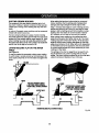
TO CROSSCUT
See Rgure 33.
A crosscut(s made by cuffing across the grain of the
workpieca. A straightcrosscutis made with the miter
table set at the 0"position.MRercrosscutsare made wlth
the miter table set at some angle otherthan zero.
• Pullout the lock pin and lift saw arm to its full height.
• Loosenthe miter lock handle.
•
•
•
Uft the miter lock plate to disengage.
Rotate the saw table until the pointer aligns with the
desired angle on the miter scale.
Rsioasethe miter lock plate.
NOTE: You can qu'_cklyk_cats_', 15°,22-1/2", 31.62",
and 45"left
orright by releasingthe lock plate as you
rotate the contr_ arm. The lock plata wil_seat itself in
one of l_e pes_ve stop notches, located in the m_ter
table frame.
24
TO BEVELCUT
• Once the saw arm has been set atthe desired angle,
securelytighten the bevet lock knob,
• Piece the workp_ecefiat on the miter table with one
es_gesecurelyagainstthe fence, if the board iswarpe_,
place the convex side against the fence, _fthe concave
edge of a board is p)aced againstthe fence, the board
could collapse on the blade st the end of the cut. jammlng the btade.
• When cutting_ong pieces of lumber or mbldlng,
supportthe oppositeend of the stock with a roller
stand or with a work surface teve_with the saw table.
See Figures 34.35.
A bevel cut is made by cuffing across the grain of the
workp{ecewith the blade angled to the work,piece. A
straight bevel cut is made with the miter table eat at the
zero degree position and the blade set at an angre
between 0"and 45".
•
•
PU[[out the lock pin and lift sew arm to its fullheight.
Loosen the miter lock handle.
•
L{f_the miter lock plate to disengage,
•
Rotate the sew table until the pointer aligns wlth zero
on the miter scale.
•
Release the miter lock plate.
• Alignthe cuffing line on the workpiece with the edge of
sew blade.
• Grasp the stock firmlywith one handand secure it
against the fence or use me optionalwork clamp or a
C-clamp to secure the workplace.
NOTE: You can quickly locate zero by releasing the
lock p_ata as you rotate the Control arm.'The lock plate
will east tteaLfin one of the built-In positive stop notches, located in the miter table frame.
•
_.
Tighten the miter lock handle securely.
_lb
WARNING: To avbld serious persona|{nit,a7,always
tighten the miter lock handle securely before mak{ng
a cut. Faitureto do so could resultin movement of
the conbol arm or miter babtewh'dema_ng e cut.
• Before turn_ngon the sew, perform a dry run of +,hecutring operat'Lon
just to make sure thatno problems will
occur when the cut is made.
• Adjustmentsof the miter fence mustbe made to correspondto the desired angle of the bevel cut prior 'm
tfting the saw arm. The fence is marked for 0% 30 °, or
45% Loosen the fence screw on the miter fence, slide
the fence to the desired position,and retightanthe
fence screw.
• Grasp the saw handle firmlythen squeezethe switch
'_rlgger.Allow several secondsfor the blade to reach
maximum speed.
• Slowlylower the blade intoand throughthe workpiece.
• Release the switch triggerand allow the saw blade to
stop ro_ling before raisingthe blade out of workpiene.
Wait until the electric brake stops blade from turnlng
befere removingthe wor!_[soe from miter ruble.
• The 45" triangle on the miter fence providesfor the
maximum clears.acerequired for adjustingthe miter
saw's anglewhen making a bevel or compound cut.
• Loosen the bevel lock knob and move the saw arm to
the left or rightto the desired bevel angle.
NOTE"When bevelingto the right,it wilt be necessary
to swivel the stop screw out of the way.
• Bevel anglescan be set from 0"to 45".
• Alignthe Indicatorpoint for the desired angle.
LEFTSn)E
INDICATOR
WARNING: To avoid serious personalinjury,
keep hands away from cutting area. Never perform
any cutting operation freehand Without holding
workpiece against the fence),The b_ade could grab
'_heworkplace Lf_tsl_psor twists.
BEVELCUT
R)GHTSIDE
INDICATOR
FENCE
SCREW
SCALE
_U_R6
B_CKET
FIg. 35
25
TO MAKE A COMPOU'ND
MITER
CUT
A compound rafter cut Is a cut made using a miter angle
and a bevel angle at the same _me. This type of cut is
used to make picture frames, cut molding, make boxes
wfth sloping sides, and for certain roofframing cuts.
To make this type of cut the contrei arm on the miter table
must be rotated to the correct angle and the saw arm
must be tilted to the correct bevel angle. Care should
always be taken when making compound miter setups
due to the interaction of the two angle settings.
Ad)ustmentsof miter and bevel sattfngs are interdependent with one another. F.schtime you adjustthe miter
eetting you change the effect of the bevel setting, Also,
each time you adjustthe bevel setting you change the
effect of the miter sethng.
tt may take several settings to obtain the desiredcut. The
first angle sa_lng should be checked after settingthe
second angle, since adjusting the second angleaffects
the first.
•
Recheck miter angle setting. Make a test cut In scrap
matedaL
•
Place the workpiece fiat on the miter table with one
edge sacureh/against
the fence, ff the board is warped,
place the convex side against the fence. The concave
edge of a board could collapse on the _ade at the end
of the cut, jamming the blade.
When cutting long pieces of lumber or molding, support the opposite end of the stock with a roller stand or
with a work surface lava/with the saw table.
•
•
•
_.
Align the cutting line on the workpiece with the edge of
saw blade.
•
Grasp the stock firmly with one hand and secure it
against the fence or use the optiona! work clamp or a
C-clamp to secure the workpiese when possible.
_1= WARNING: To avoid seriouspersona/Injury,always
keep hands away from cutting area. Never perform
any cutting operation freehand (without holding
workpisce against the fence). The b_aLdacould grab
the workpiece ff _tslips or twists.
Once the two correct settingsfor a partfcularout have
been obtained, always make a test cut In scrap material
before making a finish cut in good matedai.
•
•
•
•
•
• Before turning on the saw, performa dry run of the cutting operation lust to make sure that no problemswl!l
occurwhen the cut is made.
• Grasp the saw handle tirmiy then squeeze the switch
tdgger.A_lowseveral secondsfor the blade to reach
maximum speed.
• Slowly lower the blade into and throughthe workpiase.
Pullout the lock pin and lift saw arm to its full height.
Loosenthe miter [ock hend(e.
Liftthe miter lock p_ateto disengage.
Rotate the saw fable unt_ the pointeralignswith the
desired angle on the miter scale.
Release the miter lock plate.
NOTE: You can quloldylocate 0 °, 15°, 22-1/2 °, 31.62°,
and 45" left or fight by ra_sasingthe miter lock plate
as you rotate the controlarm. The miter lock plate will
seat itself in one of the positivestop notches, located
in miter table frame.
•
Releasethe switchtrigger and allowthe bladeto stop
rotatingbefore raisingthe blade out of werkpiece. Wait
untilthe e_ecthcbrake stops blade from turningb_fore
removingthe workplace t"rommlter ta_a,
Retightan the miter lock handle securely.
WARNING: To avoid sedous_al
injury, always
tighten the miter lock handle securelybefore making
a cut. F_ture to do so could rasuitin movement of
'{hecontrolarm or miter table wh'_tsma_ng a cut.
• Adjustmentsof the miter fence must be made to correspond to the daslred angle of the bevel cut prior to
tJlUngthe saw arm. The fence is marked for 0°, 30°, or
45 °, Loo_ the fence screw on the mit_ fence, s_de
the fence to the desired poeftlon,and ret|ghtanthe
fence screw.
• The 45° triangle on the miter fence providesfor the
maximum c{sarancerequired for adjustingthe miter
saw's angle when making a bevel or compound cut.
• Loosenthe bevel lock knob and move the saw arm to
the left or right to the desired bevel angle.
• Bevel engias can be set from 0"to 45".
• Once the saw arm has been sat at the desired angle,
sacurety tighten the bevel lock knob.
Fig. 36
26
SUPPORT LONG WORKPIECES
See Figure38.
Long workpieces need extra supports. Supportsshould
be placed along the workp)ece so it does not sag. The
support should let the workpisoe lay fiat on the base
of the saw and work table dudng the cuffingoperation.
Use the optional work clamp or s C-clamp to securethe
workpisoe.
L_, WARNING'. To avoid seriouspersonalinjury,alwsys
keep hands outside the no handszone; at least 3
in. from blade. Never perform any cuffing operation
freehand (wikhouL
holding workp'Leoe
against the
fence). The blade cupid grab the wor_pleoe i1It slips
or twists.
45"X 45"COMPOUND
MITERCOT
Fig. 37
LONGWOR|(PIECE
ROLLER
SUPPORT
Fig. 38
27
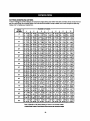
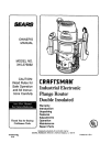
CUTTINGCOMPOUNDMITERS
"toa%d|n making the coTrectsettings,_e compound angle se_n9
chaTtbelow has been provided.,_nce compound cuts
are the most difficult to accurately obtain, trialcuts should be made in scrap matedar,and much thought and planning
made, priorto makingyour required cut.
PITCH
o =oE
4
I
5
I
6
I
7
I
s
I
9
I
to
O"
M-45"00° M-36"00°
B- 0.00° B- 0,00"
M'3D'O0° M'25"71°
B- 0,00" B- 0,00°
M-22"50°
B- 0.00"
5o
M-4_..89 ° M-35.90 °
B- 3.53" B- 2.94°
M-29.91 ° IM-25.63 °
B- 2.50 ° B- 2.17°
M-22.42 ° M-19.93 ° M-17.94 °
B- 1.91" B- 1.71" B- 1.54"
10 o
M.-.44.56° M-35.58 °
B- 7,05 = 8- 5,86°
M-29.62 °
8- 4.98°
M-22.19"
B- 3.81°
M-19.72 ° M-17.74 °
B- 3.40° 8- 3,08°
15"
M-44"0_'° M-35"06° k_-29"15°iM-24'g50 _'2_'_°
8-1Q.55 ° 8- 8.75° 8- 7,44° i B- 6.45° B- 5.68°
M'I°_'37° M'17"42°
B- 5,08° B- 4.59°
20"
M'43'22= M'34'32°
B-14,00 ° B-11.60"
M-42.19 ° M-33.36 °
B-17.39"
B-14.38 °
M'28'48°
M'24'35°
B- 9.85" 8- 8.53"
M-27.62 ° M-23.56 °
B-12.20" I B-10,57 °
M'21'27°
B- 7.52"
M-20.58 °
B- 9,31°
M'18"88°
B- 5.72"
M-18.26 Q
B- 8.31°
30 °
M-40.89 _ M-32._8 °
B-20.70"
B-17.09 °
M-28.57 _ M-22,64 °
B-14.48 ° B-12.53 °
M-!9.73 °
B- 11.03°
M-17.50 ° M-15.72 °
B- 9.85° B- 8.89°
35 °
M-39.32 ° M-30.76 b M-25.31 °
8-23.93 b 8-'t9.70 ° B"tB.6"P
M-21.53 °
8-14.41 °
M-18.74 °
B-12.68 °
M-!6.60 ° M-14,90 °
8-11.31 ° 8-10.21 °
40 °
M'37.45 ° M-29.10 °
B-27.03" B-22.20 =
M-23.86 °
B- 18,75'
M-20,25 °
B- 16.19=
M-17.60 ° M-15.58 °
B- 14.24° B- !2.70 =
M-35,26 °
B- 30.00°
M-32.73 °
B-32.80 °
M-27,19 °
B-24.56 _
M-25,03 °
B-26,76 °
M-22,,?.1=
B-20.70 °
M-20.36 °
B-22.52 °
M-18,80 °
B-17.87 °
M-17.20 °
B- 19.41°
M-16.32 ° M-14,43°1 M-12,94 °
B-15,70 ° 8-14.00 ° B-12.62 °
M-14.91 ° M-13.17°mM-11.80°
B- 17.05° B-15,19 ° B- 13.69°
55 °
M-29,84 ° M-22.62 °
8-35,40"
B- 28.78°
M-18.32 °
8-24,18 °
M-15.44 °
El- 20.82°
M-13,36 ° M-11.79°!
B- 18,27° 8- 16.27°
60 °
M-26.57 ° M-19.96 °
B-37,76 ° B-30.60 °
M-16.10 °
8-25.65 °
M-13.54 °
B-22.07 °
M-11.70 °
B-19.35 °
M-10.31 °' M- 9.23 °
8-_7.23 ° B- 15,52°
M-22.91 ° M-17.07 °
8-39.86 ° 8-32.19 °
M-13-71 °
8- 26.95°
M-11,50 °
8-23.16"
M- 9.93°
8-20.29 °
M- 8.74° M- 7.82 °
8-18.06"
8-16.25 °
M-18.68 ° M-13,95 °
8-41.64 ° B-33.53 °
M-11.17 °
8-28.02 °
M- 9,35°i M- 8.06°
B-24.06 ° B-21.08 °
M- 7.10°' M- 6,34 °
B-18.75"
B-16.88 °
25 °
45 °
50°
65°
70"
M-25.37 °
B- 4.32°
M'20"O0° M'18"00°
B- 0.00° B- 0.00 °
M'16"98°
B- 6.0"r
M-16.41 °
B- 7.50°
M-13,98 °
t3- 11.46°
M-10.56 °
8- 14.66°
i
75°
M'14.51 ° M-10.65 °
B" 43.08° 8-34.59 °
M" 8.50°
B-28.88 °
M- 7,10= M- 6.12°
B-24.78 ° B-21.69 °
M- 5.38°' M- 4.81°
B" 19.29" B- 17.37°
80°
M- 9.85° ,M- 7.19°
8.44.1,€ ° B-35.37 o
M" 5.73°
B-29.50 °
M- 4.78°1 M- 4.11° M- 3.52°' M- 3,23=
8.25.30 ° I B. 22.14_ B. 19.68= B. 17.72o
85°
M- 4.98 ° M- 3.62 °
B'44.78 ° B-35.84 °
M- 2.88°
B-29.87 =
M- 2.40°
B-25.61 =
M-2,07 °
B- 22.41 °
M-1.82 °
B- 19.92=
M- 1.62"
B- 17.93=
90 °
M- 0.00° IM" 0.00 °
_- 45._ _ B- 36.00 °
M- 0.00°
15-30.00=
M- 0.00° I M- 0.00°
_" 25.71° I_ 22,50 °
M- 0.00°
IB-20.00°
M- 0.00 °
B- 18,00°
Each B (Bevet)and M (Miter) Setting is Given to the Closest 0.005°.
COMPOUND-ANGLE SETTINGS FOR POPULAR STRUCTURES
28
CUTrlNG
CROWN MOLDING
When setting the bevel and miter angles for compound
miters, remember that the se_ings areinterdependent;
changing one angle changes the other angle as well.
"['hecompound miter sew does an excellentjob of cutting crown molding. In general, compound mRer saws do
a better jo_ of cutting crown molding then any othertool
made.
Keep in mind that the angles for crown moldings ere very
preeise end diff_cuit to set. Since it is veryeasy for these
angles to shift, all settings shoutd first be tested on scrap
molding. AJso most walls do not have angles of exactly
90", therefore, you will need to fine tune your seffings.
In order to fit properly,crown molding must be compound
miteredwith extreme accuracy.
The two contaet surfaces or_a piece of crown motdtng
that fit fiat againstthe cettlngand the wall of a room are at
anglesthat, when added together,squat exactly gO'. Most
crown molding has a top rest angle (the seetfon that fits
fiat against the ceiling)of 52"and a bottom rear angle (the
sectionthat fits fiat against the wall} of 36".
When cuffing crown molding by this method the bevel
angle should be set at 33,9" either right or left. The crown
molding stops are marked either 33.9" or 45" for the exact
angle for cutting crown molding (see figure 40).The miter
angle should be set at 31.62" either right or left, depending
on the desired cut for the application. See the chart be|ow
for correct angle settings and correct positioning of crown
molding on miter table.
LAYING MOLDING FLAT ON THE MITER
TABLE
The seffings in the chart on page 30 can be used for cutttng AJ]Standard (U.S.) crown molding with 52" and 38"
angles. The crown molding is placed/]at on the miter tsble
using the compound features of your miter sew.
See Figure 39.
"Touse this method for accuratelycutting CTownmolding
for a 90"inside or outside corner, laythe moldingwith its
broad back surface fiat on the m_tertable end against the
fence.
52"
CEILING
w
A
L
L
INSIDE
CORNER
FENCE
TOPEDGEAGMHSTFENCE• LEFTSIDE,INSIDECONNER
• RIGHTSIDE,OUTSIOE
CORMER
FENCE
BOTTOMEDGEAGAINSTFENCE
• RIGHTSIDE,iNSIDECORNER
• LEFTSIDE,OUTSIDECORNER
MITERI"NSLE
0
OUTSIDE
CORtiER
MITERTABLE
0
CROWNMOLDINGFLATONMtTER'TAlSLE
Fig. 39
29
molding.Alsomost walls do not have angles of exactty
90", therefore,you w,I need to fine tune your settings.
When cuing crown mo_inc3 by this me_od the bevel
angle shouldbe set at 0". The m_tarangle should be s_t at
45"either dght or left, depending on the desired cut for the
a_plic_on.
Using the markingson the throat plate, you can accurately
cut All Standard (U.S.) with 52"and 38"angles in sizes of
2-314 in., 3-5/8 In., and 4-5/8 in. YOUcannot use the markIngs on the throat plate when cutting crown molding with
45"and 4.5"angles.
• Loosen the crown molding stop by turningthe knob
counterclockwise.
n P_ce the stop in the hole on eitherthe left or the fight
side of the saw's b_,se.See/iguro 41.
•Wlth the bottom of the molding(wall side) against the
miter fence and the top of the molding (ceilingside)
againstthe mRertable, aUgnwith the desired mark: on
the throat plate them spk_the _own residing stop until
it fits snugglyagainst the crown molding.
• Secure the crown molding stop in place by turningthe
knob clockwise.
Fig.
Bevel
Angle
Setting
33.85"
• Hold the crown molding in place with your hand (the
side not securedwith the stop).
NOTE: NEVF_Rhaveyour hand _nsidethe no hands
zone whi_ethe sew is on.
• Slowly tower the blade mrs andthrough the wor_oisce.
• Release the switch rigger and allow the blade to stop
rotatingbefore relsing the blade out of workplace. Wait
untilthe electric brake stops blade fTomturning before
removingthe workpisce from miter table.
lype of Cut
Left side, Ioside comer
1. Top edge of molding against fence
2. Miter lathe set right 3_ .62"
3. Save taft end of cut
37,.35"
Right side, Inside comer
1. Bottom edge of molding against fence
2. Miter table set left 31.62"
3. Save left end of cut
33.85"
Left side, outside comer
1. Bottom edge of molding against fence
2. Miter table set left 31.62"
3. Save dght end of cut
33.85"
Right side, outside corner
1. Top edge of molding against fence
2. Miter tab(e set dgh_ 31.62"
3. Save fight end of cut
CUTTING
MOLDING
MOLDING
STOP
See Figures41 and 42.
USING
CROWNMOinlRO
STOP
THE CROWN
To use this method for accurately cuffing crown molding
for a g0" insideor OutSidecomer, place the crown molding
upside down on the miter table.
Keep In mind that the angles for crown moldings are very
precise and difficultto set, Since "¢_
is very esey for these
angles to shift, all seffinga should first be tested on scrap
Fig. 4.t
3O
MARKINGS
ON
THROAT
PLATE
Fig.42
WRONG
CUTTINGWARPEDMATERIAL
Fig. 44
Rgums 43 - 44.
When cuttingwarped material, elways make sure it is
positioneo'on the miter table with the convex side
against the fence as shown in figure43.
_lk
If the warped material is positionedthe wrong way as
shown in figure 44, it will pinch the blade near the completion of the cut.
WAJRHtN,G: To avo_ a kickback_ to avoid
asdous personalinjury,never positionthe concave
edge of bowed or warped material against the fence.
CLAMPING
WIDE WORKPIECES
See Figure45.
When cuttingwide workpiecas such as a 2 in. x 6 in.,
boards should be damped with a C-clamp as shown In
figure45.
WIDE
UOARD
RIGHT
Fig. 43
Fig. 45
31
,_
PIVOT ADJUSTMENTS
WARNING: Before performing any adjustment,
make sure the tool Is unplugged from the power
supply and the switch is in the OFF ( O ) position.
Failureto heed this warning could result in serious
personal Iniury.
NOTE: These adjustmentswere made at the factory and
norm=ly do not requirereadjustment.
TRAVEL
The compound miter saw has been adjusted at the factory for makingvery accurate cuts. However, soma of the
components might have moved out of alignmentduring
shipping. PJSO,over a period of time, rsadlustmentwill
probably become necessary due to wear. After unpacking
the saw, check the foflowing adjus_xnentsbefore you
begin using saw. Make any readjustmentsthat are
necessary and periodicallycheck the parts alignment
to make sure that the saw is cutting accurately.
BEVEL PIVOT ADJUSTMENT
• The compound miter saw Shouldbevel eeai)yby loosening the bevel lock knob and tiffingthe saw arm to the
left.
•
v__P0SI_VE
STOP
If movement is tight or if there is play in the pivot, have
saw repairedby a qualifiedservice tschnlclan at your
nearest Sears Service Center to avoid risk of personal
injury.
DEPTH
o I,y
PIVOT ADJUSTMENT
• The saw arm shouldfisa completelyto the up position
by flsalf,
• If the saw arm does not raise by itself or if there is play
in the pivot ioints, have saw repaired at yournearest
Service Center.
STOP
AOJUS NENT The depth stop is factory set to providemaximum cuffing
FOR
capacity for the 10 in. saw blade providedwith the saw.
LOC
NUT(S)
Fig. 46
32
j_
WARNING: When ssr_blng, use only _dentlcal
replacement parts. Use of any other part may create
a h,_._rdor c_use product da_ge.
_IL WARNING: Always wear safety goggissor safety
glasseswith side shields during power tool operation
or when blowing duet. If operation is dus_, also wear
a dust mask.
GENERAL
Avoid using solventswhen qleaning pisstlc parts. Most
plastlcaare susceptibleto damage from vadous types of
commercial solventsand may be damaged by their use.
Use clean clothe to remove dirt, carbon dust, etc.
_1_ WARNING: Do not at any t_',e let brake fluids,
gasoline, petroleum-b,'tsedproducts, penetrating
oils, etc. come in contact with plastic parts.
Chemicals Pan damage, weaken or destroy pisst[c
which may rsoutt in serious personal in)ury.
Fig.
47
BRUSH REPLACEMENT
see Figure47.
Yoursaw has externally eccessible brush assemblies that
shoutd be pedodicallychecked for wear.
Proceed as follows when replacement Is _qulred:
• Unplug the saw.
tt has been found that electric tools are subject to
eccaismtsd wear and possiblepremature failure when
they are used on fiberglassboats, sports cars, waltboard,
spacklingcompounds, or plaster.The chips and grindings
from these materialsare high,/abrasive to electdc tool
parts such as beadngs, brushes, commutators, etc.
Consequently, it is not recommended that 1histool be
used for extended work on any fiberglassmatsr_al,wallboard, spacklingcompounds, or piaster. Duringany use
on these materials it is extremely important that the tool is
cleaned frequentlyby blowing with an air let.
,_
•
LUBRICATION
•
•
All of the bearingsin this tool are lubricatedwith a sufficient amount of high grade lubdcant for the life of the unit
under normal operatingconditions.Therefore, no further
lubricationis required.
_k
•
WARNING: To ensuresafety and re_ablll_, al_
repairs -- with the exception of the externallyancessibfe brushes - should be performed by a qualified
service technicianat a Sears store to avoid dsk of
personatinjury.
•
•
33
WARNING: Fs_ureto un_j the saw could resultin
eccidental starting causing serious injury.
bnJ_'t _ap wit_. a screwdriver.Brush assembly
Is spdng _oadedand WIUpop o_ when you remove
brush cap.
Remove brushassembly,
Check for wear. Reptaca both brusheswhen either has
less than 1/4 In. length of carbon remaining. Do not
replace one side without repisctngthe other.
Reassembleusing new brush sssembIiss. Make sure
curvatureof brush matchsa curvatureof motor and
th= brush moves freelytn brush tube.
Make sure brush cap is odantad correctly (straight)and
re_iace.
Tighten brushcap securely. Do not overtighten.
R_oIa
CHANGING
THE BATTERIES
See Figure 48.
• Unp(ug the saw.
Remove the laear guide from the saw. Lay laser guide on
a fiat surfacewith the two phillipsscrews facing upward.
Remove the screws and separate the laser guide cover
from the laser guide support.
LASERGUIDE
SUPPORT
__
!
I
Remove the three button ceil batteries usinga non-conductJvede_ce such as a toothpick.
NOTE: RepLacethe batteries wRhsilveroxide batteries
that have a reting of 1.5 volt and 180 mah (mitfiampem
hour) minimum (Number 357 sliveroxide only).
LASERgUIDE
SUPPORT
(UPS_E DOWNVIEW)
When replacingthe batteries, the laser guide shouldbe
thoroughly cleaned. Use a soft paintbrushor similardevice, to remove all sawdust and debds,
APERTURE
Do not attempt to activate the laser.
The |seer is activated by means of e centrifugal switch
onty while the saw motor is runningand the laser guide is
mounted on the saw.
PLASTIC
BATIERY
UISULATOR
After cleaning laser guide and replacingbatteries, secure
laser guide cover to laser guide support usingthe two
philtipshead screws, For properassembly,be sum to
align the key on the laser guide cover with the key s]ot in
the laser guide support.Tighten screws securely,
NOTE: Aperture in laser guide cover must be aligned with
aperture (n laser guide support.
_IL
REG_VE(-)
LASER
GUIGE !
CAUTION: Use of canve(s or adjustmenfa or performance of proceduresother than those specified
_ereln may resultIn hazardousradiationexposure.
COVER
j
SLUT
Fig, 48
U_ER gUIDE
DANGER: Laser radiation when open and interlock defeated. AVOID DIRECT EYE EXPOSURE.
34
BELTREPLACEMENT
See Figure 49.
BELTCOVER
The saw is powered by a belt-driven motor. Periodically
check the belt for wear and replace it when necessary.
Proceed as follows when replacement is required:
• Unplug the saw.
WARNING: Failureto unplug ",hesaw could rseuftin
accidental starting causingserious injury.
•
Pull saw arm all the way down and engage the lock pin
to hold the saw arm in transportposition.
• Using a phi(iipascrewdriver,remove the screws from
the belt cover.Carefullylift the belt cover off the housing and set aside,
• Loosen the adjustment screws.
• Loosen the set screw on the motor housing.Pushthe
motor houslng down untllthere Is enough slack In the
belt for it to be removed from a_o_ndthe pulleys.
• Place the new belt (groovesturned to the inside}
around the bottom pulley.
• Push the motor hous(ng down with one handwhlfa
pu_lingthe be_tup and over the second pulleywith the
other hand, Fle_sesethe motor housing.
• Turn the be_tby hand un{il you are certain It is pmpedy
aligned on the grooves of the pulleys.
• Liftthe motor housing up and retlghtenthe set screw,
• Check belt tension by squeezingthe belt. Using light
pressure,the bdt shoulddeflect approximately 1/4 in.
NOTE: if belt tension is not correct, a_just the set
screw until tension is correct.
•Onse belt tension is correct, retightsnadjustment
i
SCREWS
MOTORHOUSING
SETSCREW
S_REWS
scrow8.
•
Reinstall the be(t cover wi_h the phillips screws.
BELT
Fig. 49
35
38
•
•
HI
' CRAFTSMAN
COMPOUND
MITER
SAW - MODEL
NUMBER
315.212740
44
L
I
I
I
I
I
i
i
r,_
,,,,,,/
I
\
I
Figure A
,- ,
CRAFTSMAN
COMPOUND
MITER
SAW - MODEL
NUMBER
315.212740
The modelnumberwillbe
found on a parts.
plate attached to the motor housing.Alwaysmentionthe mode(number in all correspondenceregardingyour
MITER
SAW or when ordedngrepair
!
|
PARTS LIST FOR FIGURE A
KEY PART
NO. NUMBER
DESCRIPTION
QTY.
KEY
NO.
PART
NUMBER
DESCRIPTION
QTY,
1
555516000
"Wing Nut (MS x 30 ram)................................... 1
2_
5451150O0
SlidingMiler Fence (left)...................................1
2
558511100
Clamp Bracket ................................................. 1
23
545113000
Fence............................................................... I
3
558,507200
Stop Block ....................................................... 1
24
A36030814204
* Lock Washer(MS)**STD852008 ..................... 4
4
5585121O0
* Wing Screw (1/4-20 x 12 mm) ......................... 1
25
A0710308045T
* Bolt (MS x 45 mm Soc. Hd.) ............................ 2
5
545506O0O
RollerSupportFront Brace.............................. 1
26
A07003080208
• Bolt (MS x 20 mm Soc. Hd,) ............................ 2
6
5455070O0
RollerSupport Base ........................................ 1
27
565123000
Fence Screw.................................................... 2
7
A33055056000
* Wing Nut (5/16 In.)**STD541631 .................... 1
28
545114000
Sliding MiterFence (right)................................ 1
8
54550900O
LevelingScrew (5/16 In.) ................................. 1
2g
545112000
Miter Lock Handle ........................................... 1
9
A10003040050
* Screw (M4 x 5 mm Pan Hd,)............................ 4
30
545116000
Clamp Nut ....................................................... 1
10
545511000
* W(ngScrew (MS x 20 miTt).............................. 1
31
545110000
Fixed Plata....................................................... 1
11
5455050O0
RollerSupport End Brace................................ 1
32
A10003050105
12
545508000
Roller............................................................... 1
33
545111000
13
545512000
Tab(eExtension............................................... 2
34
A35010510010
Flat Washer(MS x 10 xl t) ................................ 1
14
5655O6OO0
LowerTube, Adjustable................................... 1
35
545108000
Throat Plate..................................................... 1
15
5655O50OO
Upper Tube. Adjustable................................... 1
36
A16003050080
16
At 8003040080
565119000
Set Screw........................................................ 2
5655040O0
"Set Screw (M4 x 8 mm) ................................... 1
CrOwnMoldingClamp..................................... 1
37
17
38
565120000
Lock Spring ..................................................... 2
18
A35010823020
Fiat Washer(MS x 23 x 2t) ............................... 1
39
A59000006000
Bail................................................................... 2
19
20
565007000
565A07020
Crown MoldingKnob....................................... 1
Crown MoldingStop Assembly
(IncludesKey Nos. 14-19) ............................... 1
40
565121000
Bevel Stop (right)............................................. 1
41
565122000
BevelStop (left)............................................... I
21
545117000
Sliding Miter Fence label ................................. 2
42
565118000
"Screw (M6 x 6 mm).......................................... 2
* Screw OVl5x 10 mm Pan Hd.).......................... 6
Miter Indicator................................................. 1
* Screw _v15x 8 mm Fist Hd,)............................ 6
* Standard Hardware Item - May Be Purchased Locally
** Available From Olv. 9_ -- Source 980.00
*** Available At Your Nearest Sears Catalog Order or Retail Store
CRAFTSMAN
COMPOUND
MITER SAW - MODEL
NUMBER
315.212740
i
The
MITER
model
SAW
numberwillbe
or when orderingrepair
foundon a parts.
plate attaclled to the motor housing,Alwaysmentionthe modelnumberIn all correspondenceregardingyour
J
|
PARTS LIST FOR FIGURE A
KEY PART
NO. NUMBER
43
¢o
(o
A63000000040
QTY.
KEY
NO.
O-Ring ............................................................. 3
63
A31703010098
545102000
* Nylon Lock Nut (M10)...................................... 1
Miter Lock Plate............................................... 1
DESCRIPTION
PART
NUMBER
DESGRIPTION
Q'rY,
44
A01003060160
"Hex Bolt (M6 x 16 ram).................................... 1
64
45
A30003006003
* Hex Nut (M6) *'STD840610 ............................. 1
65
545103000
Miter Sca(o....................................................... 1
46
565115000
* Screw (M6 x 6 mm Pan Hd,)............................ 1
66
A49010020056
Rivet................................................................. 3
47
545A07030
67
568072100
69
565109000
Hand WarningLabel........................................ 2
LineLabel ........................................................ 2
48
565114000
RotlerSupportAssembly
(includes Key Nos. 5-12} ................................. 1
0' Bevel Stop ................................................... 1
69
545A07020
49
545105000
Miter Table ...................................................... 1
Work Clamp Assembly
(includesKey Nee. 70-80) .............................. 1
50
545106000
Cover Plate (left).............................................. 1
70
701107000
Quick Release.................................................. 1
51
545107000
Cover Plate(right)............................................ 1
71
A42001060300
TorsionSpring.................................................. 1
52
A19003040093
• Screw (M4x9 mm Pan Hd,)............................ 4
72
503507000
Quick ReleasePin ........................................... 1
53
$54500100
MiterTableAssembly
(IncludesKeyNos, 32, 49-52, 54, 56-68) ....... 1
73
503511000
74
A10003060158
* Screw (M6 x 15 mm Pan Hd.).......................... 1
Clamp Plate..................................................... 1
54
545109000
Miter Lock Plate............................................... 1
75
A35031020300
Fiat Washer(M 10 x 20 x 3t) ............................. 1
55
511513000
I_ser Glasses.................................................. 1
76
545503000
WorkClamp Base............................................ 1
56
545104000
Shim................................................................. 2
77
701106000
Spindle............................................................. 1
57
503118000
Rubber Grommet ........................................... 1
79
545504000
Thread Rod...................................................... 1
58
503121000
BladeWrench (5 mm)...................................... 1
79
A42001040220
Roll Pin ............................................................ 1
59
545101000
Base................................................................. 1
80
545502000
60
518106300
TableSpindle................................................... 1
61
A07910810000
* 5 mm Hex Key................................................. I
61
A35031025153
Flat Washer(M10 x 25 x 1.St).......................... 2
62
A07910610000
"6 mm Hex Key ................................................. 1
62
565124000
Spdng Washer(M10 x 25 x 1.5t) ..................... 1
63
A07910420000
* 4 mm Hex Key ................................................. 1
WorkClamp Knob ........................................... 1
* Standard Hardware item -- May Be PurChaSed Locally
** Available From DIv,98 -- Source 980.00
**" Avaiteble At Your Nearest Sears Catalog Order or Retail Store
CRAFTSMAN
COMPOUND
MITER
SAW - MODEL
NUMBER
315.2t2740
C3
19
"20
23
_14
CRAFTSMAN
COMPOUND
MITER
SAW - MODEL
NUMBER
315.212740
The
model
numberwill
be found on a plate
MITER
SAW
or when orderingrepair
parts.attached to the motorhousing.Alwaysmentionthe model numberin all correspondenceregardingyour
I
J
PARTS LIST FOR FIGURE B
KEY
NO.
PART
NUMBER
DESCRIPTION
QTY.
KEY
NO,
PART
NUMBER
OESCRIPTION
QTY.
1
545201000
BevelPivot Support......................................... 1
14
545299QOQ
2
A35O31018255 "Spring Washer (M10) **STD852010................. 2
15
A47000060002
'E' Ring........................................................... 1
3
A07003100256 "Bolt (M10 x 25 mm He:<Hd.) ........................... 2
16
854500600
4
545202000
Stop Pin Assembly
(includesKey Nos. 17-18) .............................. t
17
5
A49010025O56 Rivet................................................................. 3
545205000
Stop Pin........................................................... 1
6
$54500700
18
A63000000051
O-Ring ............................................................. 1
19
589011308
SpringWasher................................................. 1
545204000
Bevel Pivot....................................................... 1
J_
.,x
Bevel Scale...................................................... 1
Bevel PivotAssembly
(IncludesKey Nos. 1,4-5, 13, 19-20) ............. 1
Stop Pin Cap ................................................... 1
T
A01003060160 * Bo(t(M6 x 12 mm Hex Hd.) ............................. 2
20
8
538327000
Spacer ............................................................. 2
21
A,30003006003 * Hex Nut (M6) *'STD840610 .............................2
9
545208000
Shaft................................................................ 1
22
A35030401008
FlatWasher(M4x 10xlt) ............................... 2
10
545325OO0
TorsionSpring.................................................. 1
23
565204000
Bevel Indlca'cor
................................................. 2
11
A35031030300
FlatWasher (M10 x 30 x 3t)............................. 1
24
A35030408010
FlalWasher (M4 x 8 x lt) .................................2
12
545207000
Beve(Lock Knob............................................. 1
25
A10003040107 * Screw (M4 x 10 mm Pan Hd,).......................... 2
13
589010200
PivotShaft ....................................................... 1
" Standard Hardware Item -- May Be Purchased Locally
** Available From DIv.g8 - 8ourca 980.00
CRAFTSMAN COMPOUND MITER SAW - MODEL NUMBER 315.212740
""'"-
26
Note: For Laser Guide repair or
replacement,contact your nearest
Sears Se_ce Center
i
CRAFTSMAN
ii
[
COMPOUND
MITER
SAW - MODEL
NUMBER
315.212740
i
The modelnumberwi[Ibe foundon a plate attached to the motorhousing.Alwaysmentionthe model numberin all correspondenceregardingyour |
MITER SAW or when orderingrepairparts.
/
PARTS UST FOR FIGURE C
KEY
NO.
PART
NUMBER
DESCRIPTION
QTY.
KEY
NO.
PART .
NUMBER
DESCRIPTION
QTY.
1
$54500200
Blade GuardAssembly.................................... 1
15
A10003060203 * Screw (M6 x 20 mm Pan Hd.).......................... 1
2
538417000
RetainingRing................................................. 2
16
503411000
3
566407000
Rol)er............................................................... 2
17
A1900105008Q * Screwwith washer (M5 x 8 mm Pan Hd.) ....... 1
4
503402000
* Screw (MSx 8 mm Pan Hd.)............................ 4
18
503405000
ShoulderScrew ............................................... 1
5
545401000
lower BladeGuard ......................................... 1
19
545406000
Bumper ............................................................ 1
6
5034130O0
Pad .................................................................. I
20
545403000
BladeBolt Cover ............................................. 1
7
565411000
TensionSpring................................................. 1
21
503415000
* Bolt(Hex Hd.) .................................................. 1
8
503414000
Sponge............................................................ I
22
511505000
Hex Key Bolt(Laser GuideBolt)...................... 1
9
545402000
LowerGuard Plate........................................... 1
23
503412000
BladeBolt........................................................ 1
10
503407000
Sleeve.............................................................. 1
24
5880351O5
BladeWasher .................................................. 2
11
A3507061610g
FLatWasher (M6 x 16 x lt) .............................. 2
12
A31703006004 "Lock Nut (M6) .................................................. 1
13
A10003050156 "Screw (MS x 15 mm Pan Hd.).......................... 1
14
545405000
25
LinkBushing.................................................... 1
Saw Blade ....................................................... 1
26
545404000
Unk .................................................................. 1
27
$54500300
Gear Case Assembly....................................... 1
Bushing............................................................ 1
* Standard Hardware Item - May Be Purchased Locally
"* Available From DIv. 98 -- Source 980.00
*** Available At Your Nearest Soars Catalog Order or Retail Store
CRAFTSMAN
COMPOUND
MITER
SAW - MODEL
NUMBER
315.212740
31
13
/
/
29
15
\
11
IO
9.
8
SEE NOTE
CRAFTSMAN
COMPOUND
MITER
SAW - MODEL
NUMBER
315.212740
|
I
"r'_e
IM]TE
nl°de_
w SAW
numbe_
or
when will
ordering
_[_
_°und
r_p_"
on
a
Plata
_)_r_e,
a_ta_h_
t°
the
m°_°r
h°ueJng"
_waYa
m°n_J°n
the
re°de(
number
in
aI_
c°n'esP°_dant_e
r_r_Ing
y°ur
PARTS LIST FOR FIGURE D
KEY
NO.
O1
PART
NUMBER
DESCRIPTION
QTY.
KEY
NO.
PART
NUMBER
OESCRIPTION
QTY.
1
545A05020
Dust Chute Assembly...................... _,.............. 1
19
545320000
Belt (PJS08-6V)............_................................... 1
2
54532400
Stud ................................................................. 1
20
545501000
Dust Guide....................................................... 1
3
545323000
Dust Chute....................................................... 1
21
A18003060106 * Set Screw (MS x 10 ram)................................. 2
4
545322000
Dust Hood ....................................................... 1
22
545312OO0
Arbor Pulley..................................................... 1
5
A10003050127 * Screw (M5 x 12 mm Pen Hd.).......................... 1
23
A45204040080
ParallelKey (4 x 4 x 3 ram).............................. 1
6
A10003050105 * ScreW(M5 x 10 mm Pen Hd.).......................... 2
24
A35010513156
Flat Washer(M5 x 13 x 1.51}............................ 1
7
545305000
Lock Pin Plate.................................................. 1
25
A07013050126 " Bolt(MS x 12 mm Soc. Hd,) ............................ 1
8
545302000
ArborLock Pin................................................. 1
26
545319O00
g
545303000
CompressionSpdng........................................ 1
27
A10003050180 * Screw(M5 x 18 rnm Pan Hd,}.......................... 1
10
545304000
Felt................................................................... 1
28
54532100O
11
545330000
Warning Label.................................................. 1
29
A18003080250 * Set Screw (M8 x 25 ram) ................................. 1
12
545329000
Logo Plate ....................................................... 1
30
57831O0O8
Warning Label.................................................. 1
13
E07010000450
Sleeve.............................................................. 1
588005100
BrushCap ........................................................2
545327000
545A04000
Dat_ Plate........................................................ 1
14
31
32
33
565501000
15
Oust Bag .......................................................... 1
588006100
BrushAssembly ............................................... 2
16
34
545331000
BeltAdjustment WarningLabel ....................... 1
A70003060250 * ScreW (M6 x 25 mm Pan Hd.).......................... 2
17
35
A35010519150
Flat Washer(MS x 19 x 1.St)............................ 1
545328000
CarryingHandle............................................... 1
983000551
OpetatQr'SManual (Not Shown)
18
E07000846157
Cord Clamp ..................................................... 1
Motor Pulley .................................................... 1
Belt Cover........................................................ 1
Motor Assembly.............................................. 1
i
* Standaltl Hardware Item -- May Be Purr,based Locally
** AvaUableFrom Div. 98 -- Source gS0.O0
NOTE: The assembly shown representS an Important part of the Double Insulated System. To avoid t_e possibility of alteration or damage
to the system, service should be performed by your nearest E_earsRepair Center. Contact your nearest I_eersCatalog Order or Retail
Store for Service Center Information.
Your Home
For repair-in your home-of all major brand appliances,
lawn and garden equipment, or heating and cooling systems,
no matter who made it, no matter who sold itl
For the replacement parts, accessories and
owner's manuals that you need to do-it-yourself.
For Sears professional installation of home appliances
and items like garage door openers and water heaters.
1-800-4-MY-HOME
®
(1-800.469-4663)
Call anytime, day or night (U.S.A. and Canada)
www.sears.com
www.sears.ca
Our Home
For repair of carry-in items like vacuums, lawn equipment,
and electronics, cell or go on-line for the location of your nearest
Sears Parts & Repair Center.
1-800-488-1222
Call anytime,
day or night (U.S,A. only)
www.sears,com
To purchase a protection agreement (U.S.A.)
or maintenance agreement (Canada) on a product serviced by Sears:
1-800-827-6655
(U.S.A.)
Para pedir servicio de reparacibn
a domicilio, y para ordenar piezas:
1-888-SU-HOGAR
_
1-800-361-6665
(Canada)
Au Canada pour service en fran_ais:
1-B00-LE-FOYER _c
(1-888-784-6427)
(1-800-533-6937)
v_vw.sears.ca
G£ 6
® RegisteredTrademarkI TMTradem_k I =M_wiee Mad( ofSeara. R_ebu(#.and Co.
® M a_a Re_strada I TMMarca de F_bdcl I aMMar(a de _gr/i_o de _ears, Roebuck_
McM=rque de oomrne_e I _ M_I_UQd_om_e de Sears, RoebuckandCo.
CO.
O Se=_. RoebuckandCo.