1
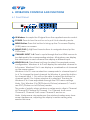
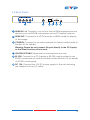
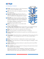
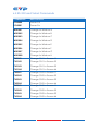
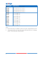
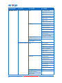
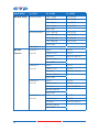
CDPS-41SQ HDMI 4×1 Seamless Quad Switcher Operation Manual DISCLAIMERS The information in this manual has been carefully checked and is believed to be accurate. Cypress Technology assumes no responsibility for any infringements of patents or other rights of third parties which may result from its use. Cypress Technology assumes no responsibility for any inaccuracies that may be contained in this document. Cypress also makes no commitment to update or to keep current the information contained in this document. Cypress Technology reserves the right to make improvements to this document and/or product at any time and without notice. COPYRIGHT NOTICE No part of this document may be reproduced, transmitted, transcribed, stored in a retrieval system, or any of its part translated into any language or computer file, in any form or by any means— electronic, mechanical, magnetic, optical, chemical, manual, or otherwise—without express written permission and consent from Cypress Technology. © Copyright 2011 by Cypress Technology. All Rights Reserved. Version 1.1 August 2011 TRADEMARK ACKNOWLEDGMENTS All products or service names mentioned in this document may be trademarks of the companies with which they are associated. SAFETY PRECAUTIONS Please read all instructions before attempting to unpack, install or operate this equipment and before connecting the power supply. Please keep the following in mind as you unpack and install this equipment: • Always follow basic safety precautions to reduce the risk of fire, electrical shock and injury to persons. • To prevent fire or shock hazard, do not expose the unit to rain, moisture or install this product near water. • Never spill liquid of any kind on or into this product. • Never push an object of any kind into this product through any openings or empty slots in the unit, as you may damage parts inside the unit. • Do not attach the power supply cabling to building surfaces. • Use only the supplied power supply unit (PSU). Do not use the PSU if it is damaged. • Do not allow anything to rest on the power cabling or allow any weight to be placed upon it or any person to walk on it. • To protect the unit from overheating, do not block anyents or openings in the unit housing that provideentilation and allow for sufficient space for air to circulate around the unit. REVISION HISTORY VERSION NO. DATE DD/MM/YY SUMMARY OF CHANGE VR0 17/10/13 Preliminary Release VS1 23/05/13 Updated Format/Diagrams CONTENTS 1. Introduction�������������������������������������������� 1 2. Applications������������������������������������������� 1 3. Package Contents�������������������������������� 1 4. System Requirements���������������������������� 1 5. Features�������������������������������������������������� 2 6. Operation Controls and Functions������� 3 6.1 Front Panel�����������������������������������������3 6.2 Rear Panel�����������������������������������������4 6.3 Remote Control���������������������������������5 6.4 RS-232 Protocols��������������������������������6 6.5 RS-232 and Telnet Commands��������7 6.6 OSD Menu����������������������������������������10 7. Connection Diagram�������������������������� 16 8. Specifications�������������������������������������� 17 9. Acronyms��������������������������������������������� 18 1. INTRODUCTION This 4×1 HDMI Seamless Quad PIP Scaler is an advanced HDMI switch with integrated Picture-in-Picture (PIP) technology that can be easily configured and controlled. It allows 4 different sources to be selected and arranged on a single display and supports video resolutions up to 1080p and audio up to 8CH/192kHz. Preset hot keys, IR and RS-232/ Telnet support allows instant control and switching. 2. APPLICATIONS • Broadcasting control room • Surveillance control room • Public advertisement displays • HDMI Input extending • Video wall system 3. PACKAGE CONTENTS • 1×4 by 1 HDMI Seamless Quad PIP Scaler • 1× Remote Control (CR-124) • 1×12/3 A DC Power Adaptor • Operational Manual 4. SYSTEM REQUIREMENTS HDMI source devices such as DVD/Blu-ray players or PC/Laptop devices and output to HDTV/monitor or to an HDMI distribution system. 1 5. FEATURES • Integration of 4 HDMI sources to a single display or video wall system • Seamless switching of HDMI channels and windows • Supports individual channel size and position adjustments • Zoom, shrink and overlay the source channels • Supports Fade-In/Fade-Out, Chromakey, Mirror and Rotation (90˚ left/right and 180˚ up or down) functions • Supports Picture-in-Picture (PIP), Picture-out-of-Picture (POP) and multi-window display • 8 Screen preset hot keys • Supports OSD, RS-232, Telnet, Remote and on-panel controls • Save and recall up to 4 customisable favorite screen arrangements 2 6. OPERATION CONTROLS AND FUNCTIONS 6.1 Front Panel WINDOW POWER MENU CHANNEL INPUT 1 2 3 1 A 2 B 3 C 4 D E 1 2 3 4 F G 1 2 3 4 H 1 2 3 4 + - 4 1 2 3 5 4 1234 6 1 IR Window: Accepts the IR signal from the supplied remote control. 2 POWER: Press to turn the unit on or to put it into standby mode. 3 MENU Button: Press this button to bring up the On-screen Display (OSD) menu on screen. 4 MINUS/PLUS (−/+): Press these buttons to navigate down/up the OSD menu. 5 CHANNEL INPUT 1~4: Press to cycle through the four HDMI sources to be displayed in the corresponding window. All windows can display the same input or each channel can display a different input. 6 WINDOW A~H: Press these hot keys to select the required screen configuration. Windows A to D will display the selected channel in full screen. Windows E to H can display a combination of channels on the same screen. Windows A to D's source selection corresponds to channel inputs 1 to 4. To change the input channel for Window A, press the button for channel input 1. You will not be able to select the buttons for channel inputs 2 to 4 when window A is selected. The sizes for Windows E to H are adjustable through the OSD menu settings. Note: Only Window G is PIP(Picture-in-Picture) whereas E, F and H are POP (Picture-out-of-Picture) modes. The order of priority when windows overlap each other is Channel 4>Channel 3>Channel 2>Channel 1 i.e Channel 4 will cover Channel 3, Channel 3 will cover Channel 2 and so on. Note: Under some circumstances the window borders may show some interference, adjusting the display's motion setting may resolve this issue. 3 6.2 Rear Panel HDMI IN 4 3 2 1 HDMI OUT CONTROL USB SERVICE ONLY 1 2 3 4 RS232 DC 12V 5 6 1 HDMI IN 1~4: Connect to up to four source HDMI equipped source devices such as DVD/Blu-ray players and or PC/Laptop devices. 2 HDMI OUT: Connect to a HD TV/monitor or HDMI matrix for display of the image. 3 CONTROL: Connect to an active network for Telnet control (refer to Section 6.5 for details). Warning: Please do not connect this port directly to the PC/Laptop as the Telnet function will not work. 4 USB SERVICE ONLY: Reserved for manufacturer use only. 5 RS-232: Connect to a PC/Laptop or RS-232 control system to use RS-232 commands to control the device (See Section 6.5 for details on RS-232 commands). 6 DC 12V: Connect the 12V DC power supply to the unit and plug the adaptor into an AC outlet. 4 6.3 Remote Control 1 Power: Press this button to switch the device on or to set it to standby mode. 2 Info: Press this button to display the device’s 2 4 firmwareersion. 3 Input CH 1/2/3/4: Press these buttons to cycle through the HDMI sources (1 to 4) for each channel to be displayed on screen. 4 WA~WH: Press these hot keys to select the screen setting where WA to WD display the selected channel in full screen and WE to WH display different combinations of all 4 channels on the same screen. Power Info WA WE CH 1 WB WF CH 2 WC WG CH 3 WD WH 5 Mute 8 Exit 1 3 CH 4 Input 6 OK Menu Audio 1 Fade In-Out FAV. 1 10 Audio 2 Chromakey FAV. 2 Audio 3 Mirror FAV. 3 12 Audio 4 Rotation FAV. 4 13 7 9 CR-124 11 14 5 Mute: Press this button to mute the audio from the HDMI output. 6 ▲▼►◄ and OK Buttons: Press these buttons to navigate through the OSD menu and press OK to enter or confirm settings. 7 Menu: Press this button to enter into the OSD menu. 8 Exit: Press this button to exit the OSD menu or settings. 9 Fade-In-Out*: Press this button to switch on or off the Fade in/out function. 10Chromakey*: Press this button to activate the Chroma key function where CH 1 is the background and CH 2 is the overlaid (top) image. 11Mirror*: Press this button to display the screen in mirror image. 12Rotation*: Press this button to rotate the image 90˚ left/right or 180˚ upside down. 13 Audio 1/2/3/4: Press these buttons to select the audio from HDMI input source 1 to 4. 14 FAV. 1/2/3/4: Press these buttons to bring up the previously stored customized screen settings. 5 Note: The functions with an asterisk (*) will only work when displaying Windows A to D. The system will revert to Window A if these functions are used when Windows E to H are displayed. 6.4 RS-232 Protocols Remote Control Switcher PIN Assignment PIN Assignment 1 NC 1 NC 2 Tx 2 Rx 3 Rx 3 Tx 4 NC 4 NC 5 GND 5 GND 6 NC 6 NC 7 NC 7 NC 8 NC 8 NC 9 NC 9 NC Baud Rate: 115200bps Data Bit: 8 bits Parity: None Flow Control: None Stop Bit: 1 6 6.5 RS-232 and Telnet Commands COMMAND POW000 DESCRIPTION Power Off POW001 Power On WND001 Change to Window A WND002 Change to Window B WND003 Change to Window C WND004 Change to Window D WND005 Change to Window E WND006 Change to Window F WND007 Change to Window G WND008 CH1001 Change to Window H Change CH1 to Source 1 CH1002 Change CH1 to Source 2 CH1003 Change CH1 to Source 3 CH1004 CH2001 Change CH1 to Source 4 Change CH2 to Source 1 CH2002 Change CH2 to Source 2 CH2003 Change CH2 to Source 3 CH2004 CH3001 Change CH2 to Source 4 Change CH3 to Source 1 CH3002 Change CH3 to Source 2 CH3003 Change CH3 to Source 3 CH3004 Change CH3 to Source 4 7 COMMAND CH4001 DESCRIPTION Change CH4 to Source 1 CH4002 Change CH4 to Source 2 CH4003 Change CH4 to Source 3 CH4004 MUT000 Change CH4 to Source 4 Mute Off MUT001 AUD001 Mute On Change Output Audio to Source 1 AUD002 Change Output Audio to Source 2 AUD003 Change Output Audio to Source 3 AUD004 FAD000 Change Output Audio to Source 4 Fade In-Out Off FAD001 CHR000 Fade In-Out On Chromakey Function Off CHR001 MIR000 Chromakey Function On Mirror Function Off MIR001 ROT000 Mirror Function On Rotation Function Off ROT001 Rotation Function Right ROT002 Rotation Function Left ROT003 SFA001 Rotation Function Upside Down Store Window Format to FAV 1* SFA002 Store Window Format to FAV 2* SFA003 Store Window Format to FAV 3* SFA004 Store Window Format to FAV 4* 8 COMMAND RFA001 DESCRIPTION Recall Window from FAV 1 RFA002 Recall Window from FAV 2 RFA003 Recall Window from FAV 3 RFA004 IO1000 Recall Window from FAV 4 CH1 Image OFF IO1001 CH1 Image ON IO2000 CH2 Image OFF IO2001 CH2 Image ON IO3000 CH3 Image OFF IO3001 CH3 Image ON IO4000 CH4 Image OFF IO4001 CH4 Image ON Note: 1. Commands with an asterisk (*) will not function under Windows A to D. 2. Commands will be not executed unless followed with by a carriage return. Commands are case-sensitive. 9 6.6 OSD Menu MAIN MENU 1ST LAYER 2ND LAYER 3RD LAYER Image Adjust Brightness Adjust CH 1 0~100 (50) CH 2 0~100 (50) CH 3 0~100 (50) CH 4 0~100 (50) Value Reset Menu Exit Contrast Adjust CH 1 0~100 (50) CH 2 0~100 (50) CH 3 0~100 (50) CH 4 0~100 (50) Value Reset Menu Exit Hue Adjust CH 1 0~100 (50) CH 2 0~100 (50) CH 3 0~100 (50) CH 4 0~100 (50) Value Reset Menu Exit Saturation CH 1 0~100 (50) CH 2 0~100 (50) CH 3 0~100 (50) CH 4 0~100 (50) Value Reset Menu Exit Picture Reset Menu Exit 10 MAIN MENU 1ST LAYER 2ND LAYER Window Setup Channel 1 Select Size 3RD LAYER CH1 Wxxx Hxxx Width Unit Width Ten Width Hundred Height Unit Height Ten Height Hundred Position CH1 Hxxxxxx Horizontal Unit Horizontal Ten Horizontal Hundred Vertical Unit Vertical Ten Vertical Hundred Image Output On/Off Window Reset Menu Exit Channel 2 Select Size CH2 Hxxxxxx Width Unit Width Ten Width Hundred Height Unit Height Ten Height Hundred Position CH2 Hxxxxxx Horizontal Unit Horizontal Ten Horizontal Hundred Vertical Unit Vertical Ten Vertical Hundred Image Output Window Reset Menu Exit 11 On/Off MAIN MENU 1ST LAYER 2ND LAYER Window Setup Channel 3 Select Size 3RD LAYER CH3 Wxxx Hxxx Width Unit Width Ten Width Hundred Height Unit Height Ten Height Hundred Position CH3 Wxxx Hxxx Horizontal Unit Horizontal Ten Horizontal Hundred Vertical Unit Vertical Ten Vertical Hundred Image Output On/Off Window Reset Menu Exit Channel 4 Select Size CH4 Wxxx Hxxx Width Unit Width Ten Width Hundred Height Unit Height Ten Height Hundred Position CH4 Wxxx Hxxx Horizontal Unit Horizontal Ten Horizontal Hundred Vertical Unit Vertical Ten Vertical Hundred Image Output On/Off Window Reset Menu Exit 12 MAIN MENU 1ST LAYER Window Setup Favorite Store 2ND LAYER 3RD LAYER FAV 1 Store On/Off/OK FAV 2 Store On/Off/OK FAV 3 Store On/Off/OK FAV 4 Store On/Off/OK Menu Exit Favorite Recall FAV 1 Recall On/Off/OK FAV 2 Recall On/Off/OK FAV 3 Recall On/Off/OK FAV 4 Recall On/Off/OK Menu Exit Menu Exit Window Channel 1 Mirror On/Off Convert Convert Fade In-Out On/Off Rotation R90/L90/180/Off Window Reset Menu Exit Channel 2 Mirror On/Off Convert Fade In-Out On/Off Rotation R90/L90/180/Off Window Reset Menu Exit Channel 3 Mirror On/Off Convert Fade In-Out On/Off Rotation R90/L90/180/Off Window Reset Menu Exit Channel 4 Mirror On/Off Convert Fade In-Out On/Off Rotation R90/L90/180/Off Window Reset Menu Exit 13 MAIN MENU 1ST LAYER 2ND LAYER 3RD LAYER Chromakey Minimum For R 000~255 Setup* Maximum For R 000~255 Minimum For G 000~255 Maximum For G 000~255 Minimum For B 000~255 Maximum For B 000~255 Switch On/Off Menu Exit Ethernet IP Mode Static/DHCP Setup Static Set IP/Mask/Gate Byte1 High XXX 000~255 Byte2 XXX 000~255 Byte3 XXX 000~255 Byte4 Low XXX 000~255 Re-Link No/Yes Exit Static/DHCP IP LINKED/NOT LINKED IP IP/Mask/Gate Mask XXX.XXX.XXX.XXX Gate XXX.XXX.XXX.XXX Mac XXX.XXX.XXX.XXX Sys Reset Information FWersion Menu Exit Note: 1. Chromakey Setup only works when CH 1and CH 2 are selected. CH 1 is the background and CH 2 is the top layer to be overlaid. 2. The Chromakey function is designed for overlapping twoideo images (such as news reports, weather forecasts or educationalideos). The background color of CH 2 is usually a single, solid, color which can be easily removed. The RGB setting is for the CH 2ideo where the minimum setting figures cannot be greater than the maximum figures and the maximum figures cannot be lower than the minimum setting figures. 3. When input 1 or 2 has no source connected a warning message will appear on the OSD. 14 7. CONNECTION DIAGRAM HDMI Camera Blu-ray Player Set-top Box 4 HDMI Inputs Router Games Console Smartphone or Tablet Device 4 3 2 1 Power Supply HDMI IN 4 3 2 HDMI OUT 1 CONTROL USB SERVICE ONLY RS232 HDMI Output DC 12V RS-232 1 2 3 4 RS-232 Enabled PC/Laptop or Control System HDTV Screen Configurations: 15 1 2 3 4 2 3 4 1 1 2 3 4 1 2 3 4 8. SPECIFICATIONS 8.1 Technical Specifications Video Bandwidth 225 MHz/6.75 Gbps Input Ports 4×HDMI Output Port 1×HDMI Input Resolution Support PC:GA~WUXGA HDTV: 480i~1080p Output Resolution Support 1080p@60 HDMI Input Cable Length Up to 15m@1080p/12-bit HDMI Output Cable Length Up to 15m@1080p/8-bit Supported Sampling Rate 32~192 kHz ESD Protection Human body model: ±8kV (air-gap discharge) ±4kV (contact-gap discharge) Power Supply 12 V/3 A DC (US/EU standards, CE/FCC/ UL certified) Dimensions 436 mm (W)×247 mm (D)×44 mm (H) Weight 2200 g Chassis Material Aluminum Chassis Color Black Operating Temperature 0 ˚C~40 ˚C / 32 ˚F~104 ˚F Storage Temperature −20 ˚C ~ 60 ˚C / −4 ˚F ~ 140 ˚F Relative Humidity 20 ~ 90 % RH (non-condensing) Power Consumption 18 W 16 8.2 Supported Resolutions RESOLUTIONS INPUT OUTPUT 640×480@60/72/75/85 - 800×600@56/60/72/75/85 - 1024×768@60/70/75/85 - 1360×768@60 - 1280×768@60/75 - 1280×1024@60/75 - 1620×1200@60 - 1920×1200@60 - 480i@60 - 576i@50 - 480p@60 - 576p@50 - 720p@50 - 720p@60 - 1080i@50 - 1080i@60 - 1080p@24 - 1080p@50 - 1080p@60 17 9. ACRONYMS ACRONYM COMPLETE TERM CEC Consumer Electronics Control DVI Digitalisual Interface HDCP High-bandwidth Digital Content Protection HDMI High Definition Multimedia Interface PIP Picture-in-Picture POP Picture out of picture IR Infrared 18 CYPRESS TECHNOLOGY CO., LTD Home page: http://www.cypress.com.tw