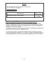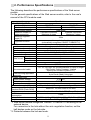
1
Web Server Module User's Manual (Installation) QJ71WS96 Thank you for purchasing the Mitsubishi programmable logic controller MELSEC-Q Series. Prior to use, please read both this manual and detailed manual thoroughly to fully understand the product. MODEL QJ71WS96-U-HW-JE MODEL 13JT97 CODE IB(NA)-0800231-C(0311)MEE 2002 MITSUBISHI ELECTRIC CORPORATION z SAFETY PRECAUTIONS z (Be sure to read these instructions before using the product.) Before using this product, read this manual and the relevant manuals introduced in this manual carefully and handle the product correctly with full attention to safety. Note that these precautions apply only to this product. Refer to the user's manual of the CPU module for the PLC system safety precautions. In this manual, the safety instructions are ranked as "DANGER" and "CAUTION". DANGER CAUTION Indicates that incorrect handling may cause hazardous conditions, resulting in death or severe injury. Indicates that incorrect handling may cause hazardous conditions, resulting in minor or moderate injury or property damage. Note that failure to observe the CAUTION level instructions may also lead to serious results depending on the circumstances. Be sure to observe the instructions of both levels to ensure personal safety. Please keep this manual in accessible place and be sure to forward it to the end user. A-1 [DESIGN PRECAUTIONS] CAUTION z Do not bundle the control lines or communication cables with the main circuit or power lines, or bring them close to each other. The distance of 100mm(3.9inch) or more should be ensured. Failure to do so cause malfunctions due to noise. z Do not power off a station where this module is mounted and do not reset the PLC CPU while storing the settings into the standard ROM of the module using a Web browser. This may make the data unstable within the standard ROM and require resetting and re-storing, or it may cause a failure or malfunctions of the module. [INSTALLATION PRECAUTIONS] CAUTION z Use the PLC in the environment specified in the user's manual of the CPU module. Failure to do so may cause electric shock, fires, malfunctions, product deterioration or damage. z When mounting the module, fully insert the module fixing projection into the corresponding fixing hole on the base unit while pressing the module fixing lever at the bottom of the module. Incorrect mounting may cause malfunctions, failures or a fall of the module. The module should be secured with screws in an environment of frequent vibration. z Be sure to shut off all phases of the external power supply before mounting or removing the module. Failure to do so may damage the module. z Tighten the screws within the specified torque range. Loose tightening may cause a fall, short circuits, or malfunctions. Overtightening may damage the screws and/or the module, resulting in a fall of the module, short circuits or malfunctions. z Do not directly touch the conductive part or electronic components of the module. This may cause malfunctions or a failure of the module. z For connector wiring, correctly press, pressure-weld or solder the connecting part by using the tool specified by the manufacturer. Poor connection may cause short circuits, fires or malfunctions. z Be sure to set the CompactFlashTM card by pressing it into the CompactFlashTM card slot. Confirm it is completely set. Poor contact may lead to malfunctions. A-2 [WIRING PRECAUTIONS] CAUTION z Be sure to fix communication cables and power cables to the module by ducts or clamps. Failure to do so may cause damage of the module or the cables due to accidental pull or unintentional shifting of the cables, or malfunctions due to poor contact of the cable. z Connect the connectors to the module securely. z Tighten the terminal screws within the specified torque range. Loose tightening may result in a fall, short circuits or malfunctions. Overtightening may cause damage to the screw and/or the module, resulting in a fall, short circuits or malfunctions. z Do not hold the communication cable by hand when pulling it out from the module. Be sure to hold the connector by hand, when removing the cable with a connector from the module. Failure to do so may cause malfunctions or damage to the module or cable. z Be careful not to let foreign matter such as dust or wire chips get inside the module. This may cause a fire, failure or malfunctions. z A protection label is attached to cover the upper part of a module to prevent the entry of foreign matter. Do not remove the label during wiring. However, be sure to remove it for heat dissipation during system operation. [TRANSPORTATION PRECAUTIONS] CAUTION z When transporting lithium batteries, make sure to treat them based on the transport regulations. (Refer to Chapter 8 for details of the controlled models.) A-3 Revisions * The manual number is given on the bottom left of the back cover. Print Date *Manual Number Revision July, 2002 IB(NA)-0800231-A First printing Nov., 2002 IB(NA)-0800231-B Correction Section 3.1(2), Chapter 4, Section 5.2(2) Nov., 2003 IB(NA)-0800231-C Correction Chapter 2, Chapter 6 Addition Safety Precautions, Section 3.1 (2), Chapter 8 This manual confers no industrial property rights or any rights of any other kind, nor does it confer any patent licenses. Mitsubishi Electric Corporation cannot be held responsible for any problems involving industrial property rights which may occur as a result of using the contents noted in this manual. 2002 MITSUBISHI ELECTRIC CORPORATION A-4 CONTENTS 1. Overview........................................................................................................ 1 2. Performance Specifications ........................................................................... 2 3. Mounting and Installation ............................................................................... 3 3.1 Handling Precautions ............................................................................... 3 3.2 Installation Environment ........................................................................... 3 4. Part Names.................................................................................................... 4 5.External Wiring ............................................................................................... 6 5.1 Connecting to the 10BASE-T/100BASE-TX ............................................. 6 5.2 Connecting to the RS-232 ........................................................................ 7 6. Setting from GX Developer ............................................................................ 8 7. External Dimensions .................................................................................... 11 8. Transportation Precautions.......................................................................... 12 8.1 Controlled Models .................................................................................. 12 8.2 Transport Guidelines .............................................................................. 12 A-5 Manuals The following table lists the manual on this product. You can order it as necessary. Relevant Manual Manual name Web Server Module User's manual Manual No. (Model code) SH-080320E (13JR58) Compliance with the EMC Directive and the Low Voltage Directive When incorporating Mitsubishi PLC into other machine or equipment and making it comply with the EMC directive and the low voltage directive, refer to Chapter 3, "EMC Directive and Low Voltage Directive" of the User's Manual (Hardware) for the CPU module. The CE logo is printed on the rating plate of the PLC, indicating compliance with the EMC directive and the low voltage directive. For making this product comply with the EMC directive and the low voltage directive, please refer to Section 3.1.3. "Cable" in Chapter 3 "EMC Directive and Low Voltage Directive" of the User's Manual (Hardware) for the CPU module. A-6 1. Overview This manual explains how to install the QJ71WS96 Web server module (hereinafter referred to as Web server module) and how to wire them with other devices. (Production list) Model name QJ71WS96 Product name QJ71WS96 Web server module 1 Quantity 1 2. Performance Specifications The following describes the performance specifications of the Web server module. For the general specifications of the Web server module, refer to the user's manual of the CPU module used. Item 10BASE-T/10BASE-TX Interface (*1) Data transmission speed Transmission method Maximum number of nodes/connection Maximum segment length(*2) Supported function RS-232 Interface Communication method Synchronization method Transmission speed Transmission distance Start bit Data format Data bit Stop bit Parity check Transmission control Recommended cable Specifications 10BASE-T 10Mbps 10BASE-TX 100Mbps Base band Cascade connection Cascade connection Maximum 4 steps Maximum 2 steps 100m Auto negotiation function (automatically recognizes 10BASE-T/10BASE-TX) Compliance with RS-232 (D-sub 9 pin) Full-duplex communication Start-stop synchronization method 9600, 19200, 38400, 57600, 115200 bps Maximum 15m 1 8 1 None Flow control (RS/CS control) is available 7/0. 127 P HRV-SV outside diameter: 8.5mm or longer (Oki Electric Cable Company, Limited Specify the number of pairs in .) External wiring applicable 9 pin D-sub (Male) fixing type connector Compact flash card Supply power voltage 3.3V 5% Size TYPE card Number of mountable cards 1 Number of occupied I/O points 32 points/1 slot (I/O assignment: intelligent 32 points) Maximum number of writes for Maximum 100,000 times to one area Standard ROM (Flash ROM) Clock Acquired from the No. 1 CPU (Every 60s) 5V DC internal current 0.65A consumption External dimensions 98 (3.86 in.) (H) 27.4 (1.08 in.) (W) 90 (3.54 in.) (D) [mm] Weight 0.17 kg (0.37Ib.) *1: Web server module recognizes 10BASE-T/10BASE-TX according to the external device. For connection to the hub without the auto negotiation function, set the half-duplex mode on the hub side. *2: Distance between the hub and node. 2 3. Mounting and Installation 3.1 Handling precautions (1) Do not drop or apply severe shock to the module case since it is made of resin. (2) Always make sure to touch the grounded metal to discharge the electricity charged in the body, etc., before touching the module. Failure to do so may cause a failure or malfunctions of the module. (3) Tighten the module fixing screws within the specified torque range as follows: Screw position Tightening torque range Module fixing screw (usually not required) 36 to 48 N•cm (M3 screw) (*1) *1:The module can be easily fixed onto the base unit using the hook at the top of the module. However, it is recommended to secure the module with the dedicated fixing screws if it is subject to significant vibration or shock. 3.2 Installation Environment For details, refer to the user's manual for the CPU module used. 3 4. Part Names [When LED cover is closed] 1) 1) 2) 3) [When LED cover is opened] 4) 5) 6) 7) 8) 4 Name 1) LED Display 10BASE-T/ 100BASE-TX interface 2) connection connector (RJ45) RS-232 interface 3) connection connector 4) EJECT button CompactFlashTM card mounting slot CompactFlashTM card 6) mounting slot cover 7) Battery 5) 8) Battery connector pin Description Refer (1) LED display contents. Used for connecting Web server module to 10BASE-T/100BASE-TX. (Web server module recognizes 10BASE-T/ 10BASE-TX according to the external device.) Used for connecting Web server module to RS-232. Used for ejecting a CompactFlashTM card from Web server module. Slot for mounting a CompactFlashTM card onto Web server module. Cover for CompactFlashTM card mounting slot. Battery for file protection. Connector pin for battery lead. (The battery lead is not connected to the connector at shipment to prevent battery consumption.) (1) LED display LED name LED status ON RUN OFF OFF ERR. ON Flickering ON CH2 SD/RD OFF ON 100M OFF ON SD/RD OFF Description Normally operating (It may take some time until RUN LED turns ON after the module is started.) Watch dog timer error occurrence (Hardware error) Normal operation Module continue error Module stop error CH2 side: data receiving or data sending Data not transmitted 100Mbps 10Mbps CH1 side: data receiving or data sending Data not transmitted 5 5. External Wiring 5.1 Connecting to the 10BASE-T/100BASE-TX Use the twisted pair cable that meets IEEE802.3 10-BASE-T/100BASE-TX standards when connecting to the 10BASE-T/10BASE-TX interface. (1) For 100Mbps Use either of the following cables. (a) Unshielded twisted pair cable (UTP cable), Category 5 (b) Shielded twisted pair cable (STP cable), Category 5 (2) For 10Mbps Use either of the following cables. (a) Unshielded twisted pair cable (UTP cable), Category 3 (4,5) (b) Shielded twisted pair cable (STP cable), Category 3 (4,5) TIP During the high speed communication (100Mbps) via 100BASE-TX connection, a communication error may occur due to the effect of high frequency noise generated from the device other than PLC, depending on the installation environment. Take the following countermeasures on the Web server module side to eliminate the effect of high frequency noise. (1) Wiring y Do not bundle the twisted pair cables with the main circuit or power cables or bring them close to each other. y Make sure to place the twisted pair cable in a duct. (2) Cable y In the environment where the cable is susceptible to noise, use the shielded twisted pair cable (STP cable). (3) 10Mbps communication y Connect the 10Mbps-compatible device with Web server module, and then transmit the data to the device at transmission speed of 10Mbps. 6 5.2 Connecting to the RS-232 Use the RS-232 cable when connecting to the RS-232 interface. (1) RS-232 connector specifications 1 6 2 7 3 8 4 9 5 Pin No. 1 2 3 4 5 6 7 8 9 Signal abbreviation CD(DCD) RD(RXD) SD(TXD) ER(DTR) SG(GND) DR(DSR) RS(RTS) CS(CTS) CI(RI) Signal name Signal direction Web module Modem Data Carrier Detect Received Data Transmitted Data Data Terminal Ready Signal Ground Data Set Ready Request To Send Clear To Send Ring Indicator (2) RS-232 interface connector The Web server module uses the following RS-232 interface connector. 9 pin D-sub (Female) fixing type Use either of the following products as a connector shell for the connection cable on the Web server module side. y 3M Plug type: 8209-6009 Shell type: 3702-2209 M2.6 y Tyco Electronics AMP K.K. Plug type: 747904-2 Shell type: 747515 or 174469-2 y Connector fitting screw (M2.6) (3) RS-232 cable Use the RS-232-compliant cable of up to 15m. [Recommended cable] 7/0. 127 P HRV-SV... Specify the number of pairs in . (for 13 pairs, specify 7/0. 127 13P HRV-SV.) (Oki Electric Cable Company, Limited) 7 6. Setting from GX Developer Set the mode, default operation, battery error detection, logging monitor setting and response monitoring time for Web server module on the "Intelligent function module switch setting" screen. Switch Number Description Switch 1 Mode setting Default operation/Battery error detection setting/ Switch 2 logging monitor setting Switch 3 (lower byte) Response monitoring time setting Switch 4 to 5 For system (not set) (1) Mode setting (Switch 1) Select the operation mode for Web server module. Setting Number Item Description 0000H Online Normal operation mode Tests the ROM/RAM/switch 0001H Hardware test settings Tests the self diagnostics for 0002H CH1 Self-loopback test CH1. Tests the self diagnostics for 0003H CH2 Self-loopback test CH2. 9999 Module initialization Initializes the module to default (270FH) mode setting. 8 (2) Default operation/Battery error detection setting/logging monitor setting (switch 2) b15 to Speccify 0. * b5 b4 b3 0 b2 b1 b0 Switch 2 Logging monitor setting Default operation setting (Account setting) 0: Not display the latest file update time. 0: Operates according to the account setting. 1: Operates according to the default setting. User name : QJ71WS96 Password : MITSUBISHI Access authority : Device write/Tag component write/ Administrator Initial screen : Standard screen top page 1: Displays the latest file update time. Battery error detection setting 0: Detects battery error. 1: Not detect battery error. Default operation setting (System setting) 0: Operates according to the system setting. 1: Operates according to the default system setting. IP address : 192.168.3.3 Subnet mask : 255.255.255.0 Connecting through LAN or the router. Use the default HTTP port number (80). Use the default FTP port number (21). System name : QJ71WS96 Does not execute network diagnoses (Ping). Automatic connection to network at start-up. * A switch setting error (0180h) will occur during hardware test if this area is other than 0. Default operation setting (IP filter setting) 0: Operates according to the IP filter setting. 1: Operates according to the default IP filter setting. The IP packet with no filter setting is passed. (Without filter setting) (a) Default operation setting (bit 0, 1) For the account setting, system setting and IP filter setting, whether the default setting is enabled or not is set in this setting. 1) Account setting (bit 0) 0: Operates according to the account setting. 1: Operates according to the default setting. 2) System setting and IP filter setting (bit 1) 0: Operates according to the system setting/IP filter setting. 1: Operates according to the default setting. (b) Battery error detection setting (bit 2) This setting is provided to determine whether battery error detection is enabled or not while the Web server module is operating without battery. 0: Detects battery error. 1: Not detect battery error. 9 (c) Logging monitor setting (bit 4) Whether the latest file update time is displayed or not in the file specification field of the logging monitor is set in this setting. 0: Not display the latest file update time. 1: Displays the latest file update time. (3) Response monitoring time setting (switch 3 (lower byte)) This is the setting for timeout time (second) from when a module sends a request to the CPU of the accessed device until the CPU responds to it. Response timeout error will occur if the CPU of the accessed device does not respond to the request after the set time has passed. Setting range: 15 to 255 (second) (default value: 15 seconds) Response monitoring time will be automatically default value (15 seconds) if it is not set or set to any of 0 to 14. b15 to (Upper byte) * b8 b7 to (lower byte) b0 Specify 0. * Swich 3 Response monitoring time setting * The upper byte is basically ignored. However, a switch setting error (0180h) will occur during hardware test if the upper byte is other than 0. 10 15 to 255 (seconds) Response monitoring time will be automatically default value (15 seconds) if it is not set or set to any of 0 to 14. 98 (3.86) 7. External Dimensions R1 (*1) 27.4 (1.08) 14 (0.55) 90 (3.54) Cable diameter 4 + 10 R2 (*2) (Units:mm (in.)) *1: The bending radius near the connectors (reference value: R1) should be four times as long as the cable's outside diameter or more when connecting the twisted pair cable. *2: The bending radius near the connectors (reference value: R2) should be four times as long as the cable's diameter or more when connecting the RS-232 cable. CompactFlash is a trademark of SanDisk Corporation. Other company names and product names used in this document are trademarks or registered trademarks of respective companies. 11 8. Transportation Precautions When transporting lithium batteries, make sure to treat them based on the transport regulations. 8.1 Controlled Models The lithium batteries used with the Web server module are classified as indicated in the following table: Product name Q series battery Model Q6BAT Product supply status Lithium battery Classification for transportation Non-dangerous goods 8.2 Transport Guidelines Comply with IATA Dangerous Goods Regulations, IMDG code and the local transport regulations when transporting products after unpacking or repacking, while Mitsubishi ships products with packages to comply with the transport regulations. Please consult your carrier for further details. 12 Warranty Mitsubishi will not be held liable for damage caused by factors found not to be the cause of Mitsubishi; machine damage or lost profits caused by faults in the Mitsubishi products; damage, secondary damage, accident compensation caused by special factors unpredictable by Mitsubishi; damages to products other than Mitsubishi products; and to other duties. For safe use y This product has been manufactured as a general-purpose part for general industries, and has not been designed or manufactured to be incorporated in a device or system used in purposes related to human life. y Before using the product for special purposes such as nuclear power, electric power, aerospace, medicine or passenger movement vehicles, consult with Mitsubishi. y This product has been manufactured under strict quality control. However, when installing the product where major accidents or losses could occur if the product fails, install appropriate backup or failsafe functions in the system. Country/Region Sales office/Tel Brazil MELCO-TEC Rep. Com.e Assessoria Tecnica Ltda. AV. Paulista 1471, Conj. 308, Sao Paulo City, Sao Paulo State, Brazil Tel : +55-11-283-2423 Germany Mitsubishi Electric Europe B.V. German Branch Gothaer Strasse 8 D-40880 Ratingen, GERMANY Tel : +49-2102-486-0 U.K Mitsubishi Electric Europe B.V. UK Branch Travellers Lane, Hatfield, Herts., AL10 8XB,UK Tel : +44-1707-276100 Italy Mitsubishi Electric Europe B.V. Italian Branch Centro Dir. Colleoni, Pal. Perseo-Ingr.2 Via Paracelso 12, 20041 Agrate B., Milano, Italy Tel : +39-039-6053344 Spain Mitsubishi Electric Europe B.V. Spanish Branch Carretera de Rubi 76-80 08190 - Sant Cugat del Valles, Barcelona, Spain Tel : +34-93-565-3131 France Mitsubishi Electric Europe B.V. French Branch 25 Boulevard des Bouvets, F-92741 Nanterre Cedex, France TEL: +33-1-5568-5568 South Africa Circuit Breaker Industries LTD. Tripswitch Drive, Elandsfontein Gauteng, South Africa Tel : +27-11-928-2000 Hong Kong Ryoden Automation Ltd. 10th Floor, Manulife Tower, 169 Electric Road, North Point, HongKong Country/Region Sales office/Tel China Ryoden Automation Shanghai Ltd. 3F Block5 Building Automation Instrumentation Plaza 103 Cao Bao Rd. Shanghai 200233 China Tel : +86-21-6475-3228 Taiwan Setsuyo Enterprise Co., Ltd. 6F., No.105 Wu-Kung 3rd.RD, Wu-Ku Hsiang, Taipei Hsine, Taiwan Tel : +886-2-2299-2499 Korea HAN NEUNG TECHNO CO.,LTD. 1F Dong Seo Game Channel Bldg., 660-11, Deungchon-dong Kangsec-ku, Seoul, Korea Tel : +82-2-3660-9552 Singapore Mitsubishi Electric Asia Pte, Ltd. 307 ALEXANDRA ROAD #05-01/02, MITSUBISHI ELECTRIC BUILDING SINGAPORE 159943 Tel : +65-6473-2308 Thailand F. A. Tech Co.,Ltd. 898/28,29,30 S.V.City Building,Office Tower 2,Floor 17-18 Rama 3 Road, Bangkpongpang, Yannawa, Bangkok 10120 Tel : +66-2-682-6522 Indonesia P.T. Autoteknindo SUMBER MAKMUR Jl. Muara Karang Selatan Block A Utara No.1 Kav. No.11 Kawasan Industri/ Pergudangan Jakarta - Utara 14440 Tel : +62-21-663-0833 India Messung Systems Put,Ltd. Electronic Sadan NO:111 Unit No15, M.I.D.C BHOSARI,PUNE-411026 Tel : +91-20-712-2807 Australia Mitsubishi Electric Australia Pty. Ltd. 348 Victoria Road, PostalBag, No 2, Rydalmere, N.S.W 2116, Australia Tel : +61-2-9684-7777 HEAD OFFICE : 1-8-12, OFFICE TOWER Z 14F HARUMI CHUO-KU 104-6212, JAPAN NAGOYA WORKS : 1-14, YADA-MINAMI 5-CHOME, HIGASHI-KU, NAGOYA, JAPAN When exported from Japan, this manual does not require application to the Ministry of Economy, Trade and Industry for service transaction permission. Specifications subject to change without notice. Printed in Japan on recycled paper.