1
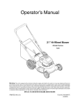
Operator's Manual
Riding Mower
Internal Bagging System
27.5" Cutting Deck
Model Series 320
IMPORTANT:
Read safety rules and instructions
carefully
before operating
equipment.
Warning:
This unit is equipped with an internal combustion engine and should not be used on or near any unimproved forestcovered, brush-covered or grass-covered land unless the engine's exhaust system is equipped with a spark arrester meeting
applicable local or state laws (if any). If a spark arrester is used, it should be maintained in effective working order by the operator.
In the State of California the above is required by law (Section 4442 of the California Public Resources Code). Other states may have
similar laws. Federal laws apply on federal lands. A spark arrester for the muffler is available through your nearest engine authorized
service dealer or contact the service department, P.O. Box 361131 Cleveland, Ohio 44136-0019.
MTD LLC, P.O. BOX361131CLEVELAND,OHIO44136-0019
PRINTED IN U.S.A.
FORM NO. 770-10077D
(11/2001 )
TABLEOFCONTENTS
Content
Page
Important Safe Operation Practices ............................................................................
3
Slope Gauge ...............................................................................................................
6
Assembling Your Riding Mower ..................................................................................
7
Know Your Riding Mower ............................................................................................
9
Operating Your Riding Mower .....................................................................................
11
Making Adjustments ....................................................................................................
13
Servicing Your Riding Mower ......................................................................................
16
Maintaining Your Riding Mower ...................................................................................
17
Off-Season Storage ....................................................................................................
Troubleshootin{ ..........................................................................................................
19
20
Parts List .....................................................................................................................
22
FINDINGMODELNUMBER
This Operator's Manual is an important part of your new riding mower. It will help you assemble, prepare
and maintain the unit for best performance. Please read and understand what it says.
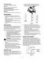
Before you start assembling your new equipment, please locate the model plate on the
equipment and copy the information from it in the space provided below. The information on
the model plate is very important if you need help from our Customer Support Department or
an authorized dealer.
You can locate the model plate by pivoting the cover upward and looking under the frame. A sample
model plate is explained below. For future reference, please copy the model number and the serial
number of the equipment in the space below.
(Model Number)
www.yardman,com
,
(Serial
Number)
_, MTO
LLC
P.O. BOX 361131
CLEVELAND,OH 44136
330-220-4683
800-800-7310_
Copy the model number here:
Copy the serial number here:
ENGINEINFORMATION
The engine manufacturer is responsible for all engine-related issues with regards to performance, powerrating, specifications, warranty and service. Please refer to the engine manufacturer's Owner's/Operator's
Manual packed separately with your unit for more information.
CALLINGCUSTOMER
SUPPORT
If you have difficulty assembling this product or have any questions regarding the controls, operation or
maintenance of this unit, please call the Customer Service at the number below.
Call 1- (330) 220-4MTD (4683) or 1- (800)-800-7310 to reach a Customer Support
representative. Please have your unit's model number and serial number ready when you
call. See previous section to locate this information. You will be asked to enter the serial
number in order to process your call.
SECTION1: IMPORTANT
SAFEOPERATION
PRACTICES
_hb
WARNING:
This symbol
important
safetyand
instructions
which,
if not followed,
could in this
endanger the personal
safetypoints
and/orout
property
of yourself
others. Read
and follow
all instructions
manual before attempting to operate your riding mower. Failure to comply with these instructions may result
in personal injury. When you see this symbol--heed its warning.
Your riding mower was built to be operated according to the rules for safe operation in this manual. As with any type
of power equipment, carelessness or error on the part of the operator can result in serious injury. If you violate any
of these rules, you may cause serious injury to yourself or others.
_lb
ARNING:
Engine exhaust,
some of its constituents,
emit chemicals known to State of California
reproductive harm.
GeneralOperation
•
•
•
•
•
•
•
•
•
Read, understand, and follow all instructions in the
manual and on the machine before starting. Keep
this manual in a safe place for future and regular
reference and for ordering replacement parts.
Only allow responsible individuals familiar with the
instructions to operate the machine. Know controls
and how to stop the machine quickly.
Do not put hands or feet under cutting deck or near
rotating parts.
Clear the area of objects such as rocks, toys, wire,
etc., which could be picked up and thrown by the
blade. A small object may have been overlooked
and could be accidentally thrown by the mower in
any direction and cause injuryto you or a
bystander. To help avoid a thrown objects injury,
keep children, bystanders and helpers at least 75
feet from the mower while it is in operation. Always
wear safety glasses or safety goggles during
operation or while performing an adjustment or
repair, to protect eyes from foreign objects. Stop
the blade(s) when crossing gravel drives, walks or
roads.
Be sure the area is clear of other people before
mowing. Stop machine if anyone enters the area.
Never carry passengers.
Disengage blade(s) before shifting into reverse and
backing up. Always look down and behind before
and while backing.
Be aware of the mower and attachment discharge
direction and do not point it at anyone. Do not
operate the mower without either the entire grass
catcher or the chute guard in place.
Slow down before turning. Operate the machine
smoothly. Avoid erratic operation and excessive
speed.
Never leave a running machine unattended.
Always turn off blade(s), place transmission in
and certain vehicle components
contain or
to cause cancer and birth defects or other
•
•
•
•
•
•
•
•
•
•
neutral, set park brake, stop engine and remove
key before dismounting.
Turn off blade(s) when not mowing.
Stop engine and wait until blade(s) comes to a
complete stop before (a) removing grass catcher or
unclogging chute, or (b) making any repairs,
adjusting or removing any grass or debris.
Mow only in daylight or good artificial light.
Do not operate the machine while under the
influence of alcohol or drugs.Watch for traffic when
operating near or crossing roadways.
Use extra care when loading or unloading the
machine into a trailer or truck. This unit should not
be driven up or down a ramp onto a trailer or truck
under power, because the unit could tip over,
causing serious personal injury. The unit must be
pushed manually on a ramp to load or unload
properly.
Never make cutting height adjustment while engine
is running, if operator must dismount to do so.
Wear sturdy, rough-soled work shoes and closefitting slacks and shirts. Do not wear loose fitting
clothes or jewelry. They can be caught in moving
parts. Never operate a unit in bare feet, sandals, or
sneakers.
Check overhead clearance carefully before driving
under power lines, wires, bridges or low hanging
tree branches, before entering or leaving buildings,
or in any other situation where the operator may be
struck or pulled from the unit, which could result in
serious injury.
Disengage all attachment clutches, thoroughly
depress the brake pedal, and shift into neutral
before attempting to start engine.
Your mower is designed to cut normal residential
grass of a height no more than 10". Do not attempt
to mow through unusually tall, dry grass (e.g.,
pasture) or piles of dry leaves. Debris may build up
onthemowerdeckorcontacttheengineexhaust
presenting
a potentialfirehazard.
Never assume that children will remain where you
last saw them.
•
SlopeOperation
•
•
Slopes are a major factor related to loss of control
and tip-over accidents which can result in severe
injury or death. All slopes require extra caution. If
you cannot back up the slope or if you feel uneasy
on it, do not mow it.
For your safety, use the slope gauge included as
part of this manual to measure slopes before
operating this unit on a sloped or hilly area. If the
slope is greater than 15 ° as shown on the slope
gauge, do not operate this unit in that area or
serious injury could result.
Do:
•
•
•
•
•
•
•
•
Mow up and down slopes, not across.
Remove obstacles such as rocks, limbs, etc.
Watch for holes, ruts or bumps. Uneven terrain
could overturn the machine. Tall grass can hide
obstacles.
Use slow speed. Choose a low enough gear so that
you will not have to stop or shift while on the slope.
Always keep machine in gear when going down
slopes to take advantage of engine braking action.
Follow the manufacturer's recommendations for
•
•
•
•
•
•
•
•
•
Do Not
•
•
•
•
•
Do not turn on slopes unless necessary; then, turn
slowly and gradually downhill, if possible.
Do not mow near drop-offs, ditches or
embankments .The mower could suddenly turn over
if a wheel is over the edge of a cliff or ditch, or if an
edge caves in.
Do not mow on wet grass. Reduced traction could
cause sliding.
Do not try to stabilize the machine by putting your
foot on the ground.
Do not use grass catcher on steep slopes.
Children
•
Tragic accidents can occur if the operator is not
alert to the presence of children. Children are often
attracted to the machine and the mowing activity.
Never carry children. They may fall off and be
seriously injured or interfere with the safe machine
operation.
Never allow children under 14 years old to operate
the machine. Children 14 years and over should
only operate machine under close parental
supervision and proper instruction.
Use extra care when approaching blind corners,
shrubs, trees or other objects that may obscure
your vision of a child or other hazard.
Remove key when machine is unattended to
prevent unauthorized operation.
Service
wheel weights or counterweights to improve
stability.
Use extra care with grass catchers or other
attachments. These can change the stability of the
machine.
Keep all movement on the slopes slow and gradual.
Do not make sudden changes in speed or direction.
Rapid engagement or braking could cause the front
of the machine to lift and rapidly flip over backwards
which could cause serious injury.
Avoid starting or stopping on a slope. If tires lose
traction, disengage the blade(s) and proceed slowly
straight down the slope.
Keep children out of the mowing area and in
watchful care of an adult other than the operator.
Be alert and turn machine off if children enter the
area.
Before and when backing, look behind and down
for small children.
•
•
•
Use extreme care in handling gasoline and other
fuels. They are extremely flammable and the
vapors are explosive.
a. Use only an approved container.
b. Never remove fuel cap or add fuel with the
engine running. Allow engine to cool at least
two minutes before refueling.
c. Replace fuel cap securely and wipe off any
spilled fuel before starting the engine as it may
cause a fire or explosion.
d. Extinguish all cigarettes, cigars, pipes and
other sources of ignition.
e. Never refuel the machine indoors because fuel
vapors will accumulate in the area.
f.
Never store the fuel container or machine
inside where there is an open flame or spark,
such as a gas hot water heater, space heater
or furnace.
Never run a machine inside a closed area.
To reduce fire hazard, keep the machine free of
grass, leaves or other debris build-up. Clean up oil
or fuel spillage. Allow machine to cool at least 5
minutes before storing.
Before cleaning, repairing or inspecting, make
certain the blade and all moving parts have
stopped. Disconnect the spark plug wire, and keep
the wire away from the spark plug to prevent
accidental starting.
Check the blade and engine mounting bolts at
frequent intervals for proper tightness. Also,
visually inspect blade for damage (e.g., excessive
wear, bent, cracked). Replace with blade which
meets original equipment specifications.
Keep all nuts, bolts and screws tight to be sure the
equipment is in safe working condition.
•
•
•
•
•
•
Nevertamperwithsafetydevices.Checktheir
properoperationregularly.
Useallguardsas
instructed
inthismanual.
Afterstrikinga foreignobject,stoptheengine,
removethewirefromthesparkplugandthoroughly
inspectthemowerforanydamage.Repairthe
damagebeforerestarting
andoperating
themower.
Grasscatchercomponents
aresubjecttowear,
damageanddeterioration,
whichcouldexpose
movingpartsorallowobjectstobethrown.Foryour
safetyprotection,
frequently
checkcomponents
andreplacewithmanufacturer's
recommended
partswhennecessary.
Mowerbladesaresharpandcancut.Wrapthe
blade(s)orwearglovesanduseextracautionwhen
servicingblade(s).
Checkbrakeoperation
frequently.
Adjustand
serviceasrequired.
Muffler,engineandbeltguardsbecomehotduring
operation
andcancausea burn.Allowtocooldown
beforetouching.
Donotchangetheenginegovernorsettingsor
overspeed
theengine.Excessive
enginespeeds
aredangerous.
Observeproperdisposallawsandregulations.
Improper
disposaloffluidsandmaterialscanharm
theenvironment
andtheecology.
a. Priortodisposal,determine
thepropermethod
todisposeofwastefromyourlocalofficeof
Environmental
Protection
Agency.Recycling
centersareestablished
toproperlydisposeof
materialsinanenvironmentally
safefashion.
b. Usepropercontainers
whendrainingfluids.Do
notusefoodorbeverage
containers
thatmay
misleadsomeoneintodrinkingfromthem.
Properlydisposeofthecontainers
immediately
followingthedrainingoffluids.
c. DONOTpouroilorotherfluidsintotheground,
downa drainor intoastream,pond,lakeor
otherbodyofwater.ObserveEnvironmental
Protection
Agencyregulations
whendisposing
ofoil,fuel,coolant,brakefluid,filters,batteries,
tiresandotherharmfulwaste.
Illustrated
belowaretherepresentation
ofthesafetylabelsontheequipment.
Fora fulllistofpartnumbers
andlocationofallthelabels,seepage38.
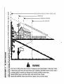
ASSEMBLECHUTEDEFLECTOR
TOTHIS UNIT BEFOREOPERATING,
o
.,
SIGHT AND HOLD
L _
|
IIq
"_ _" "_ _" _
I q
THIS LEVEL WITH
A POWER
POLE
A CORNER
!
A VERTICAL
TREE
OF A BUILDING
OR A FENCE
POST
Ill
tv
Ill
Ill
-1
Ill
_z
cO
tv
Ill
I-Ill
o5
€._
,,,
O3
40
.J
,,,Z
z
W
mll.
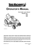
WARNING
Do not mow on inclines with a slope in excess of 15 degrees (a rise of approximately 2-1/2 feet every 10 feet).
A riding mower could overturn and cause serious injury. If operating a walk-behind mower on such a slope, it
is extremely difficult to maintain your footing and you could slip, resulting in serious injury.
Operate RIDING mowers up and down slopes, never across the face of slopes.
Operate WALK-BEHIND
mowers across the face of slopes, never up and down slopes.
SECTION3: ASSEMBLING
YOURRIDINGMOWER
•
•
•
•
•
Remove all screws and staples from the crate.
Holding sides of the crate firmly, lift top of the crate
up and set it aside. Avoid tire punctures.
Remove and discard plastic bag covering the unit.
Lift the rear of the mower and clear the bottom of
the crate. Repeat for the front.
Be sure the parking brake is disengaged. See
Figure 8 for location of the parking brake. Roll unit
out of the crate.
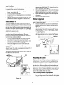
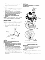
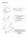
LooseParts
•
•
•
•
•
•
1.
2.
Remove loose parts from the grass catcher and/or
the crate very carefully. Compare with list and
illustration (Figure 1) below.
Mulching plug & side-discharge chute
Oil drain sleeve
3.
4.
5.
Bumper (optional)
Ignition keys (not shown)
Operator's manual (not shown)
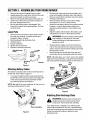
Attach the red battery cable to the positive terminal
(marked +), and the black battery cable to the
negative terminal (marked -) on the battery. See
Figure 3.
Align the cables with the slots in the battery cover
and tighten the screws on the battery terminals.
d_lb
WARNING:
Press the battery cables against
side of battery so that these do not make
contact with flange of rider frame when it is
opened or closed.
•
,_ide-Discharge _
•
"
Remove both wing nuts securing the battery and
cover to the battery hold-down rods. See Figure 3.
Remove red and black insulation caps from battery
terminals. See Figure 3
Remove battery terminal screws with a Phillips
screw driver or a 10 mm. socket wrench.
Oil D_in
Reassemble the battery cover to the hold-down
rods on two ends with the two wing nuts removed
earlier. Check to ensure that the cables pass easily
through slots in cover.
Place right hand on the left side of the seat and
slowly lower the hood assembly until fully closed.
NOTE:
Do not place your hand around
the bottom
edge of the hood assembly; it may get pinched between
the hood assembly
Plug
and grass
ca tcher or the frame rail.
Bumper
Figure 1
Battery
Cover_
AttachingBatteryCables
Wing
Nut Negative
Terminal
Wing
Nut
Positive
The battery is located under the hood assembly above
the left rear wheel. Refer to Figure 3.
•
To access the battery, lift the hood assembly from
the left side of the hood only. Stand on the right side
of the unit and pivot the hood assembly towards
you until fully opened. See Figure 2.
NOTE: Do not lift the hood assembly by the two vent
openings located behind the seat.
Battery
Frame
Figure 3
AttachingSide-Discharge
Chute
4_
WARNING:
Battery posts, terminals and
related accessories contain lead and lead
compounds. Wash hands after handling.
I_l'ood Assembly
Figure 2
Your riding mower is shipped to you with the grass
catcher fully assembled on the unit. A side-discharge
chute and a mulching plug are included as loose parts.
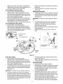
Follow the instructions below to attach the sidedischarge chute.
•
,_
WARNING:
DO not operate the mower if any
one or more of the grass catcher, discharge
chute or mulching plug is not firmly installed on
the mower.
•
•
•
•
•
Pivot the hood assembly up and lower the cutting
height adjustment lever to the lowest position.
Remove the two wing nuts (A and B in Figure 4 )
from two ends of the grasscatcher chute.
Loosen the wing nut (C in Figure 4 ) in the middle of
the chute. Do not remove.
Slide the grasscatcher chute to the right and out of
the deck frame. Slide the side-discharge chute in
and place it on the deck so that the three wing nut
positions align with those on the deck.
Reinsert wing nuts A and B. Tighten all three.
_rass Catcher
hute
•
•
To attach the mulching plug now to the unit, follow
instructions on previous page to attach sidedischarge chute to the deck.
Place wing nut on each of the hex bolts and thread
a few turns. See Figure 5. Check that the mulch
plug is aligned correctly within the discharge chute.
Tighten both wing nuts
AttachingBumper(if equipped)
•
•
•
•
Remove bumper from the grass catcher inside
which it was shipped.
Loosen and remove the two pairs of hex bolts and
lock nuts from the front rail on the riding mower.
See Figure 6.
Align the two holes on the bumper tube with the
corresponding holes on the rider frame (from where
you removed the hardware). See Figure 6.
Re-insert the two hex bolts through the bumper and
the rider frame and secure with the two lock nuts.
Lock
Nut
4,.
L
Rider Frame
Rail
=
Figure 4
AttachingHitchPlate(ifequipped)
AttachingMulch Plug
While operating your riding mower, you have three
options: (i) to collect grass clippings in the grass
catcher, (ii) to discharge grass clippings on the side, or
(iii) to mulch grass and recirculate clippings back to the
lawn. For the third option, attach the mulching plug to
the side-discharge chute and then to the deck.
•
Put two hex bolts through the mulching plug at the
respective openings. See Figure 5.
Place speed nuts over the hex bolts.
/Side
Wing Nut
Speed
Nut
_ Hex Bolt
Figure 6
Nut
•
Bumper
Discharge Chute
The hitch plate, if so equipped, was loosely attached to
the rear frame of the rider for shipping purposes.
•
•
•
•
Loosen the nut attaching the hitch plate to the
frame and swing the plate outward. Make sure that
the wider side of the hitch plate aligns with the rear
frame as shown in Figure 7.
Remove the hex bolt, lock washer and hex nut from
the other end of the rear frame. Save the hardware.
Align the hole on the hitch plate with the
corresponding hole on the rear frame assembly
(from where you removed the hardware).
Re-insert the hex bolt through the hitch plate and
the rear frame. Secure with lock washer and hex
nut removed earlier. See Figure 7. Tighten both
sets of hardware.
Hitch Plate
A
Rear
Hex BOI_
_
Plug
Washer
Figure 5
Insert the plug into the side-discharge chute
aligning the two slots on two sides of the sidedischarge chute with those on the mulching plug.
Hex
N_
Figure 7
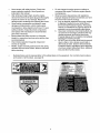
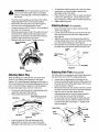
SECTION4: KNOWYOURRIDINGMOWER
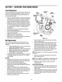
Compare the illustrations in Figure 8 with your riding mower to familiarize yourself with the location of various
controls and adjustments.
_
WARNING:
The operation of any riding mower can result in foreign objects being thrown into the
operator's eyes, causing severe eye damage. Always wear safety glasses before operating the mower, or
while performing any adjustments or repairs on it.
Seat
Steering Wheel
Throttle/Choke
Control
Shift Lever
Indicator
--
Cutting Height
Adjustment Lever
Blade Engagement
Pedal
Ignition
Switch
Side Discharge
Chute
Pedal
\\
Cutting
Deck
Brake
Pedal
Hood
_Assembly
Parking
Engine
Blade
Engagement
Pedal
Blade
Lock
Figure 8
Throttle/ChokeControl
Shift Lever
Use to regulate the engine speed and to start the
engine.
Use to change direction of the mower.
"Go" Pedal
Use to regulate the ground speed of the riding mower.
Use to determine the level of grass clipping in the bag
and when to stop and empty it.
Ignition Switch
Parking Brake
Use to turn the engine ON or OFF.
Use to stop the mower from moving while parked.
Grass Fill Level Indicator
Blade EngagementPedal
•
Use to engage or disengage the blade.
Blade Lock
Before you move the shift lever to any of the
positions, depress the brake pedal and stop the
unit. Keep your foot on the brake pedal.
Use to lock blade at the engaged position.
CuttingHeightAdjustmentLever
Use to raise and lower the cutting deck which
determines the cutting height.
Brake Pedal
Use to stop the mower's forward or reverse motion.
StoppingMower
•
•
•
•
•
Release blade engagement pedal all the way.
Release the "Go" Pedal and depress the brake
pedal.
When the mower comes to a complete stop, place
the shift lever in neutral.
Engage the parking brake by pulling up on the
parking brake knob.
Turn the ignition key to OFF position and remove
the key.
Figure 9
•
SafetyInterlock
This unit is equipped with a safety interlock system for
your protection. The interlock safety switches are
connected to the brake pedal, the blade engagement
pedal, the shift lever, and the seat.
•
The purpose of the safety interlock system is threefold:
a.
b.
c.
,_
to prevent the engine from starting unless the
brake pedal is depressed and the blade
engagement pedal is disengaged;
to shut off the engine if the blade pedal is not
disengaged when the shift lever is put into
reverse; and
to shut the engine off when the operator leaves
the seat without engaging the parking brake.
•
GrassFill LevelIndicator
This indicator (Figure 10 ) was designed to add
convenience to your riding mower. While the mower is
running, air will flow through the discharge chute and
into the grass catcher. If the grass catcher is empty, air
flows through easily pushing the ball up. If the grass
catcher is full, air does not flow through it allowing the
ball to fall. So if you see the ball in the grass catcher fill
level indicator falling down, you should stop the mower
and empty the bag.
WARNING:
To avoid
risk mower
of serious
injury, do not operate
thethe
riding
if the
interlock system is malfunctioning.
•
•
•
•
Move the lever outwards (left) to remove the
locking pin from the lever and slide the lever to the
position desired. Look at the rear and make sure
the path is free of obstacles before positioning the
shift lever to the reverse.
Do not force the shift lever. If it does not shift,
release the brake pedal slightly to line up the
shifting collar in the transmission, then try to move
the shift lever.
Slowly release the brake pedal and take your foot
off the pedal. Always make sure that there is no one
in the way when you run the mower.
Remove objects that could be thrown by the
blade(s).
Know location and function of all controls.
Be sure blade(s) and engine are stopped before
placing hands or feet near blade(s).
Before leaving operator's position, disengage
blade(s), place the shift lever in neutral, engage
parking brake, shut engine off and remove key.
Fill
Level
indicator
UsingShiftLever
The shift lever is used to regulate the direction of your
riding mower. It can be set at forward, neutral, or
reverse settings. These settings, marked as F, N,and R
respectively, are located next to the shift lever on the
unit. See Figure 9.
Figure 10
10
SECTION5: OPERATING
YOURRIDINGMOWER
UsingThrottle/ChokeControl
•
The throttle/choke control is used to increase or
decrease the speed of the engine.The FAST and the
SLOW positions are marked with illustrations of a rabbit
and a turtle respectively. See Figure 9.
•
•
•
•
•
For normal operation and when using a grass
catcher, move the throttle/choke control to the
FAST position.
For maximum charging of the battery and also for a
cooler engine while running, move the throttle/
choke control to the FAST position.
For transport and to tow pull-behind attachments,
move the throttle/choke control to the SLOW
StartingMower
•
•
•
•
•
position.
Do not adjust the governor to increase or decrease
the engine speed. The governor is set at the factory
for maximum engine performance, and should not
be altered.
•
•
With your right foot on the brake pedal, move the
shift lever to the neutral position.
Continuing to hold down the brake pedal with your
right foot, pull up the parking brake knob. Make
sure the parking brake holds the unit.
Release the brake pedal. Stop the engine and
remove the ignition key. Now your riding mower is
parked.
•
•
REVERSE position as you desire. Look to the rear
and check before backing up.
Release the brake pedal.
Depress the "Go" Pedal.
To stop, release the "Go" Pedal and depress the
brake pedal.
Press the blade engagement pedal downward until
the blades are turning.The blades can be engaged
either while the mower is in motion or while it is
NOTE: Your riding mower is equipped with a blade lock
to keep the blade engaged without the operator having
to depress the blade pedal continuously. See Figure 8.
To engageparkingbrake
Completely push the brake pedal down and stop
the unit.
Depress the brake pedal so that the parking brake
is disengaged.
Place the shift lever in either the FORWARD or the
standing.
UsingParkingBrake
•
Turn the ignition key to the START position. As
soon as the engine starts, let the key return to the
ON position.
Move throttle/choke control out of CHOKE position
and into FAST throttle position.
To engage the blade lock: While pressing down
on the blade pedal, push the blade lock down with
your heel. It should click into the "blade engaged"
position. To disengage the blade lock, simply push
down on the blade pedal and release the lock.
,_
WARNING:
When the blades are engaged,
keep hands and feet away from the discharge
opening, the blades or any part of the deck.
To release the parking brake
•
StoppingMower
Depress the brake pedal. The parking brake will be
automatically disengaged.
•
•
BeforeStarting
Service the engine with gasoline as described in the
engine manual. Check the oil level.
•
•
,_
WARNING:
Never fill fuel tank indoors, or
•
when engine is running or hot. Do not smoke
while filling up the gasoline tank.
NOTE: Do not leave the key in the ON position when
you are not operating the mower. Such action will drain
the battery dead.
StartingEngine
•
•
•
•
Release blade engagement pedal all the way.
Release the "Go" Pedal and depress the brake
pedal.
When the mower comes to a complete stop, place
the shift lever in neutral.
Engage the parking brake by pulling up on the
parking brake knob.
Turn ignition key to OFF position and remove key.
Attach the wire to the spark plug.
Depress the brake pedal with your right foot.
Set throttle/choke control in the CHOKE position
(all the way forward).
Place the shift lever in the NEUTRAL position.
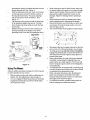
ToEmptyGrassCatcher
•
•
11
Stop the mower completely, pull up on the
parking brake knob and take the ignition key out.
Get off the operator's seat.
Pivot the hood assembly up. Pull up the
grasscatcher bag by the handle and take it to the
proper disposal site. See Figure 11 .
Hold the bag away from your body. Push down
on the bag lever and let the bottom section of
the bag fall downwards. The grass clippings
will be disposed of from the bottom. See
Figure 11.
Tap the bag on the ground so that the three legs
of the bag press against the ground. The bag
lever should snap close while you push the bag
downwards.
•
Replace the bag on to the mower making sure
the bag is placed on the flange on top of the
discharge chute. Pivot the hood assembly down.
•
•
•
When mowing an area for the first time, watch out
for objects lying on the grass. If you strike a foreign
object, stop the engine. Remove wire from spark
plug and thoroughly inspect the mower for any
damage. Repair the damage before operating it
again.
Avoid scalping the lawn by adjusting the cutting
height upwards and/or sharpening the blades.
Mow at full throttle. Learn the terrain on which you
are mowing. For best mowing results, mow only
when the grass is dry.
The recommended mowing pattern is given below:
S
Grass Catcher
Bag
•
•
Assembly
•
Figure 11
•
UsingTheMower
Observe safety rules listed on pages 3-5 of this manual
for safe operation of your mower.
•
•
•
Before mowing, make sure that the cutting deck is
leveled. For deck adjustment, refer to page 14.
You can engage the blade by pressing on the blade
engagement pedal with your left foot while sitting
on the operator's seat.
•
12
Mow grass often and in regular intervals so that you
can cut only 1/3 of the grass blade in one mowing.
To empty grass bag, stop the mower completely,
engage the parking brake, and turn the ignition off.
This will prevent the hot engine exhaust gas from
browning the grass.
Many communities no longer haul grass clippings
to landfills. Composting the clippings from your
grass catcher is a viable solution. For this you will
have to empty the grass catcher at the designated
composting site.
Your riding mower is equipped with a mulching plug
to mulch the grass and recycle into the lawn instead
of collecting in the grasscatcher bag.
Mulch only when the grass is dry. Mulching wet
grass may damage the underside of the deck
because wet grass tends to stick to it. Clean deck
thoroughly if you mulch wet grass.
For effective mulching, overlap mowing paths so
that the clippings are distributed evenly.
SECTION6: MAKINGADJUSTMENTS
"Go" Pedal
,_
WARNING:
DO not at any time make any
Adjustment to the "Go" Pedal is made at the cable end.
See Figure 12.
adjustment to the mower without first stopping
engine and disconnecting spark plug wire.
•
•
•
BrakePedal
During normal operation of the riding mower, the brake
is subject to wear and tear. Check the brake
periodically by carrying out the following test:
•
•
•
Release the parking brake and place the riding
mower in neutral. Depress the brake pedal and try
to roll the riding mower. The tractor should not
move. If the tractor moves, adjust the brake.
•
•
,_
WARNING:
Do not adjust
the engine is running.
Be surethe
to brake
block while
the
•
wheels of the riding mower before making any
adjustments on the brake cable.
•
•
•
•
•
Reconnect the spark plug wire and pivot the hood
assembly down.
CuttingHeight
Adjustment to the brake pedal is made at the cable end.
See Figure 12.
•
•
•
Set the parking brake and turn ignition key off.
Shift the cutting height lever to the lowest position.
Pivot the hood assembly up and remove the
grasscatcher bag and the side-discharge chute or
the mulching plug from the mower.
Disconnect wire from the spark plug.
Locate the speed control cable under the front
housing. See Figure 12.
Loosen the jam nuts and back the cable out to
tighten or thread inward to loosen as shown.
Retighten the jam nuts when proper tension is
reached.
The deck cutting height adjustment lever is located on
the hood assembly. For a representation of the cutting
height positions, refer to Figure 9.
Set the parking brake and turn ignition key off.
Shift the cutting height lever to the lowest position.
Pivot the hood assembly up and remove the
grasscatcher bag and the side-discharge chute or
the mulching plug from the mower.
Disconnect wire from the spark plug.
Locate the brake cable on the right side under the
front housing. See Figure 12.
Using a pair of 1/2" wrenches, loosen the jam nuts
and back the cable out to tighten or thread inward
to loosen. See Figure 12 inset.
Retighten the jam nuts when proper tension is
reached.
Unlock parking brake and repeat the test described
above. Readjust if necessary.
•
•
•
•
Pull the lever out of the slot and slide it upward or
downward to the desired cutting height.
Lower the cutting height to mow close to the
ground.
Raise the deck height to the highest position when
you ride on a sidewalk or a road.
To mow tall or thick grass, move the cutting height
adjustment lever to the highest position and cut.
Then move the lever to a lower position and cut
again.
Brake
Cable
Conkol
Cable* m
Jam Nuts
jhten
Loosen
*Same type of adjustment
(on{y one shown here)
Figure 12
13
on both cables
SeatPosition
•
The seat position on the riding mower can be adjusted
to maximize the operator's convenience.
•
•
•
•
•
Stop the mower completely and engage the parking
brake. Turn ignition off.
Pivot the hood assembly up.
Loosen the four self-tapping screws on the bottom
of the seat.
Slide the seat forward or backward in the slot, and
position it as desired. Retighten the four screws.
•
•
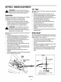
WheelAlignment
The front wheels should toe-in 1/16-5/16 inch. To adjust
toe-in, follow these steps:
•
Remove the 3/8" hex nut and lock washer which
BladeBrake/PTO
The blade engagement pedal should be adjusted so
that if you depress it about 3/4" from the front of the slot,
it should start engaging the deck belt. The PTO (power
take off) switch is located in the blade brake slot on the
left side of the upper frame. See Figure 13. The brake
engagement pedal needs to make contact with the PTO
switch for the engine to start.
•
Under normal operation, the blade engagement pedal
should not require frequent adjustment. However,
perform the following test periodically and make sure
that it is in fine working condition.
•
•
•
If the belt is slipping when you depress the blade
engagement pedal about 3/4", loosen the two hex
nuts on the cable. See Figure 13.
If the belt is engaging sooner than when the blade
engagement pedal is 3/4" from the PTO switch,
tighten both hex nuts on the cable. See Figure 13.
Repeat the blade engagement test and readjust if
necessary.
Pivot the hood assembly back.
•
holds the ball joint to the steering segment. See
Figure 14.
Adjust the ball joint in or out until the wheels toe-in
approximately 1/16-5/16" (Dimension "B" should
be approximately 1/16-5/16" less than dimension
"A"). See Figure 14.
Replace the ball joint into the steering segment,
and replace the 3/8" hex nut and the lock washer.
Hex Nut
Pivot the hood assembly up and check if there is
enough slack on the deck engagement cable.
Depress the blade engagement pedal (about 3/4
inch) and check if the belt is engaging.
If the cable is tight or too loose or the belt is not
engaging, adjust the deck engagement cable.
Steerin
Segment
NOTE: The deck engagement cable will be correctly
adjusted when the cable moves approximately 1/2" off
center line in both directions.
Washer
Rod
Ball
Joint
Adjustment to the blade brake will have to be made at
the cable end. See Figure 13.
Deck
Engagement
Cable
L/16_5/16" _ess than /
Hex
Nut
Figure 14
Adjustingthe Deck
There are three tests for checking deck levelling on the
riding mower. The results of each test will determine
what kind of levelling, if at all, the equipment needs.
Blade
Pedal
S
IMPORTANT: Perform adjustments to the deck on a flat,
level surface. Before continuing with deck adjustment,
check air pressure in all four tires. Recommended air
pressure is 12 psi. Please note that the valve stems on
this riding mower are on the inside of the front wheels
and on the outside of the rear wheels.
Engagement
Test1: CheckingRear DeckHeightAdjustment
•
Lift the hood assembly and remove grass catcher
from the riding mower. Place the deck in the highest
position.
itch
Figure 13
14
•
Inspect rear of deck. If the deck is contacting the
cable bracket on the front of the transmission, you
will have to adjust the rear deck height.
•
•
Test 2: CheckingFront to Rear Levelling
•
•
•
Place the deck in the highest position.
Wearing a pair of heavy work gloves to prevent
injury, rotate the cutting blade so that it is pointed
front to back and parallel to the rider. Depress and
lock the deck engagement pedal.
Measure the distance from the front and the rear
•
tips of the blade to the ground.The front should be
approximately 1/4" to 3/8" lower than the rear.
If the distance is higher, level the deck front to rear.
AdjustingRear Deck Height
•
Completely loosen, but do not remove, the top hex
nut out of the three hex nuts that hold the hex bolt
and the ferrule on the deck hanger link assembly.
See Figure 15.
IMPORTANT: Do not try to loosen/tighten
nut.
•
•
Test 3: CheckingSide to Side Levelling
•
•
Measure the distance from the tips of the blade to
the ground.
If the two distances are unequal, level the deck
side to side.
Place the deck in the highest position.
Wearing a pair of heavy work gloves to prevent
injury, rotate the cutting blade so that it is pointed
side to side and perpendicular to the rider. Depress
and lock the deck engagement pedal.
•
•
the bottom
Thread the middle nut as far down as possible.
Locate the lower links at the rear of the deck.
Working on one side at a time, disconnect the
helper springs from them.
Remove each lower link by removing both hair pin
clip and washers.
Reattach the lower links as shown in Figure 15
inset.
Helper
Spri
LOOsen hex nuts
to adjust
not adjust hex nut
Remove Hairpin Clips
and Washers
Lever
"Hanger
Link
Figure 15
Front to RearLevelling
•
•
•
•
•
Place the deck in the highest position.
Wearing a pair of heavy work gloves to prevent
injury, rotate the cutting blade so that it is pointed
front to back and parallel to the rider. Depress and
lock the deck engagement pedal.
Completely loosen, but do not remove, the top hex
nut out of the three hex nuts that hold the hex bolt
Side to Side Levelling
•
•
and the ferrule on the deck hanger link assembly.
See Figure 15.
IMPORTANT: Do not try to loosen/tighten
•
•
Thread the middle nut up against the base of the
ferrule. See Figure 15.
Tighten the upper nut against the top of the ferrule
to lock adjustment.
•
bottom nut.
•
Thread the middle nut as far down as possible.
Keeping an equal number of threads above each of
the nuts, thread the upper nut down until the front
tip of the blade is 1/4" to 3/8" lower than the rear tip
of the blade. Note that threading this nut down will
raise the front of the deck.
•
15
Place the deck in the highest position.
Wearing heavy work gloves to prevent injury,rotate
the cutting blade so that it is pointed side to side
and perpendicular to the rider. Depress and lock
the deck engagement pedal.
Loosen the middle hex nut.
Thread the top hex nut up or down in order to set
both tips of the blade at an equal height from the
ground. Remember to thread the nut down to raise
the deck, and thread up to lower the deck.
Once the deck is level, thread the middle hex nut to
tighten against the ferrule. Make sure the cut is
even and the lift lever moves to all cutting heights.
SECTION7: SERVICING
YOURRIDINGMOWER
FuseReplacement
The fuse is located next to the spark plug under the rear
frame. Fuses seldom fail without a reason. If the fuse
blows, the source problem must be corrected or the
new fuse wilt blow again.
•
Check for loose connections in the fuse holder and
•
•
•
•
•
•
replace holder if necessary. A dead short may be in
the cranking or charging circuit where insulation
may have rubbed through and exposed bare wire.
Replace the wire or repair with electrician's tape if
the wire strands have not been damaged. Also look
for a wire pinched between body panels, burned by
the exhaust pipe or muffler, or rubbed against a
moving part.
Stop the riding mower and engage the parking
brake. Remove ignition key.
Pivot the hood assembly up. Disconnect the spark
plug wire and ground it.
Pull the fuse out of the lead wire.
Replace with new automotive fuse.
Make sure to reconnect the spark plug wire before
Pulley
Screw
Pulley
Figure 16
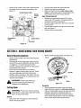
BeltReplacement
•
There are two drive belts and one deck belt in your
riding mower; follow the description below to identify
the belts.
•
1.
Lower drive belt goes from the variable speed
pulley to the transmission pulley.
2. Upper drive belt goes from the variable speed
pulley to the upper sheave of engine pulley.
3. Deck pelt goes from the deck pulley to the
lower sheave in engine pulley.
Periodically check to see if these belts are too loose
or damaged through wear and tear. If so, replace
with new belt.
•
•
•
•
Remove belt from around deck pulley, idler pulley,
and the engine pulley.
Place the new belt around the deck pulley and the
engine pulley making sure that the belt is routed
inside the belt keepers. There are two belt keepers
under the grass catcher, one on the idler and the
other under the deck belt cover. See Figure 16.
Reinstall deck belt cover and secure with two selftapping screws, lock washer and hex nut.
NOTE: Belt keeper ",4" must be mounted on the outside
of the bell
•
Deck Belt
•
Belt
Keeper "A"
Cover_
pivoting the hood assembly back.
•
Imaginary
Line
'
Belt
Keeper
Make sure to align the belt keeper in line with the
frame. See Figure 16.
NOTE: An imaginary line between the belt keeper and
idler pulley should be parallel to frame. See Figure 16.
Engage the parking brake and turn the ignition off.
Pivot the hood assembly up and remove the grass
catcher. Remove the spark plug wire.
Put the deck at the lowest cutting height by
adjusting the cutting height adjustment lever to the
lowest position.
Using a 1/2" socket wrench, remove two selftapping screws, lock washer and hex nut that hold
the deck belt cover to the deck. See Figure 16. For
this, you will have to work from the top left side of
the mower. Remove the belt cover.
•
Replace the grass catcher and pivot the hood
assembly back.
Lower Variable SpeedBelt
•
•
Using a 9/16" wrench, loosen the hex nut on the
idler pulley. See Figure 16.
16
Remove the rear deck belt guard following first five
steps for deck belt removal. Remove belt from the
engine pulley.
Push the spring loaded idler, located on the left side
of the transmission, to the right. Remove belt from
around the idler and then the transmission pulley.
See Figure 17.
Using a 9/16" socket, remove bolt, spacer and the
flat washer from the variable speed pulley. See
Figure 17.
Variable Speed Pulley
Spring
•
•
•
keeper, and the belt keeper is reassembled in the
same location from where it was removed.
Spring
Loaded
Upper Variable SpeedBelt
Idler
•
Remove the engine pulley using a 5/8" socket
wrench with a 6" extension. The engine pulley is
located in front of the transmission.
•
Drop the engine pulley down and remove the belt
from around it.
•
Push the idler bracket to the right and remove the
belt. See Figure 17.
Replace belt and reassemble.
•
Transmission
Pulley
Drop the pulley down and remove the belt.
Replace new belt and reassemble.
Make sure that the belt is routed inside of belt
Engine Pulley
Figure 17
SECTION8: MAINTAININGYOURRIDINGMOWER
GeneralRecommendations
•
Always observe safety rules when performing any
maintenance.
•
The warranty on this riding mower does not cover
items that have been subjected to operator abuse
or negligence. To receive full value from the
warranty, operator must maintain the riding mower
as instructed in this manual.
We do not recommend the use of pressure
washers or garden hose to clean your unit. These
may cause damage to electrical components,
spindles, pulleys, bearings or the engine. The use
of water may shorten life of your riding mower and
reduce its serviceability.
•
Remove blade from the spindle. See Figure 18.
De
Spindle
Blade
,_
WARNING:
Always
stop before
engineany
and
disconnect spark
plug wire
Figure 18
maintenance or adjustments.
Sharpening
CuttingBlade
,i_
WARNING:
•
Protect your hands by wearing
heavy gloves or using a rag to grasp the cutting
blade. Avoid personal injury.
when rotating at high speeds, may cause damage
to the mower and/or cause personal injury.
Removal
•
When sharpening the blade, follow the original
angle of grind as a guide. It is extremely important
that each cutting edge receives an equal amount of
grinding to prevent an unbalanced blade. An
unbalanced blade will cause excessive vibration
Remove the 5/8" hex flange nut which holds the
blade to the blade spindle.
17
•
Lubrication
The blade can be tested for balance by balancing it
on a round shaft screwdriver. Remove metal from
See Figure 20 for an illustration of the lube points
described below.
the heavy side until it balances evenly.
Reassembly
•
•
•
•
Before reassembling the blade to the unit, lubricate
the spindle with light oil (or engine oil).
Be sure to properly align "star" fitting on blade with
"star" on spindle.
When replacing the blade, be sure to install the
blade with the side of the blade marked "Bottom" (or
with part number) facing the ground when the
mower is in the operating position.
Blade Mounting Torque: 70/90 foot-pounds
maximum.
kube
NOTE: To ensure safe operation, all nuts and bolts
must be checked periodically for correct tightness.
Lube
OilDrainSleeve
Your riding mower has a plastic oil drain sleeve, packed
with the loose parts, for draining oil from the crankcase.
•
•
To drain the oil, snap small end of the oil drain
sleeve onto oil sump. See Figure 19.
Remove drain plug and drain oil into a suitable
container.
Lube
Oil Drain
Sleeve
Figure 19
Lube
(before
reassemby)
Engine
Refer to the separate engine manual for engine
maintenance instructions.
•
•
•
Viewed from the bottom
Maintain engine oil as instructed in the separate
engine manual packed with your unit. Read and
follow instructions carefully.
Poor engine performance and flooding usually
indicates that the air cleaner should be serviced.
Service air cleaner as per the engine manual.
Clean frequently under extremely dusty conditions.
The spark plug should be cleaned and the gap
reset once a season. Spark plug replacement is
recommended at the start of each mowing season.
Check engine manual for correct plug type and gap
specifications.
Figure 20: Lubrication Chart
BladeAssembly
•
Lubricate blade assembly and deck spindle only
while reassembling the blade either after
sharpening or replacement.
Pivot Points
•
Lubricate pivot points with light oil once a season.
SteeringShaft and Gear
•
Lubricate steering shaft and spline at least once a
season with light oil.
18
•
Lubricate teeth of the external steering gears with
automotive multi-purpose grease every 25 hours of
operation or once a season.
•
Linkage
•
Lubricate all deck linkage and height adjustment
linkage with a light oil.
•
Front Wheels
•
Lubricate at least once a season with automotive
•
multi-purpose grease.
Engine
•
Maintain the engine as recommended in the
separate engine manual.
Promptly wipe off any fuel or oil spilled on the
machine with clean cloth.
•
Clean the underside of the blade housing after
each mowing. Do not let clippings or debris
accumulate around the blade which may cause rust
on the deck.
If engine muffler is equipped with spark arrester
screen, remove and clean the screen regularly.
Replace if damaged or plugged with debris.Clean
muffler area and remove any grass or other debris
before operating the unit.
FuelFilter
CleaningEngine
•
Using a brush or cloth, remove grass, chaff or
debris from the finger guard on the engine daily to
prevent overheating of the engine. Do not clean
with a forceful spray of water since water
contaminates the fuel system.
Keep the governor linkage, springs and controls
free of debris.
Your unit is equipped with a replaceable in-line fuel
filter. Replace filter whenever contamination or
discoloration is noticed. Order replacement filter
through your engine authorized service dealer.
SECTION9: OFF-SEASON
STORAGE
If the machine is to be inoperative for a period longer
than 30 days, prepare for storage as follows.
NEVER store battery without a full charge.
Recharge battery before returning to service or
every two months, whichever occurs first.
When storing unit for extended periods,
disconnect battery cables and remove the battery
from the unit.
Clean dirt and chaff from cylinder, cylinder head
fins, blower housing, rotating screen and muffler
area.
Riding Mower
•
•
•
•
Clean the engine and the entire unit thoroughly.
Lubricate all pivot points. Wipe the entire
machine with an oiled rag to protect the surfaces.
Store unit in a clean, dry area. Do not store next
to corrosive materials, such as fertilizer.
When storing any type of power equipment in an
unventilated or metal storage shed, care should
be taken to rustproof the equipment. Using a light
oil or silicone, coat the equipment, especially any
chains, springs, bearings and cables.
Engine
•
Battery
•
Charge battery fully. The battery loses some of
its charge each day when the unit is not used.
19
Refer to the engine manual for storage
instructions. Make sure to store the engine
properly so that your equipment can work
smoothly afterwards.
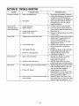
SECTION10: TROUBLE-SHOOTING
Trouble
Excessive vibration
Mower wilt not
discharge grass or
leaves uncut strips
Broken Belt
Belt comes off
Belt shreds
Possible Cause
Remedial Action
1.
Bent or damaged blade
1.
2.
Bent blade.
2.
1.
2.
Engine speed low.
Speed selection.
1.
3.
4.
Cutting height set too low.
Blades short or dull.
3.
4.
Sharpen or replace blades (uncut strip
problem only).
1.
Sudden stop or shock load to belt
1.
2.
Incorrect belt used
2.
3.
Belt engaged abruptly
3.
4.
Defective or damaged belt
4.
Inspect rider for cause such as foreign
objects stuck in between deck and
frame or belt path. Remove
obstruction and check for damage.
Replace belt if needed.
Replace with proper belt. Check Parts
list in this manual for correct part
number.
Engage belt slowly by depressing the
blade engagement pedal slowly.
Replace with proper belt. Follow
instructions on page 16.
1.
Belt too loose; stretched
1.
2.
Broken or weak idler spring
2.
1.
Belt guides or guards incorrectly adjusted
1.
2.
Pulleys not aligned
2.
Pulley rusted or in otherwise bad condition;
frozen bearing
3.
3.
2.
2O
Stop engine immediately. Check all
pulleys, blade adapters, keys and bolts
for tightness and spindle damage.
Tighten or replace any damaged parts
Stop engine immediately. Replace
damaged blade. Only use original
equipment blades.
Throttle must be set at full throttle.
Use lower ground speed. Slower the
ground speed, better the quality of cut.
Raise the deck.
Readjust belt. Replace if needed.
Follow instructions for belt
replacement on page 16.
Replace. Order with correct part
number from Parts List in this manual.
Adjust belt guides and guards so that
these are approximately 1/16 to 1/8
inch from belt when engaged.
Realign pulleys to be within
approximately 1/16 inch of each other.
Check with straight edge. Make sure
fastening hardware is tight.
Replace pulleys. Order with correct
part number from the Parts List in this
manual. Adjust new pulleys to 1/16 ".
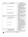
Trouble
Possible Cause
Remedial Action
Engine will not crank 1. Safety switch button not depressed
2.
1.
Battery installed incorrectly
2.
3.
Battery dead or weak.
3.
4.
Blown fuse or circuit breaker
5.
Engine ground wire loose.
4.
5.
Engine cranks but
will not start
1.
Throttle/choke not in starting position.
1.
2.
3.
No fuel to the carburetor
Fuel line or in-line fuel filter plugged
2.
4.
No spark to spark plug
3.
4.
5.
Faulty spark plug
5.
6.
Dirty air cleaner
6.
Engine smokes
1.
2.
3.
Engine oil has been overfilled
Dipstick not seated or broken
Engine loses crankcase vacuum
1.
2.
3.
There are two switches in the starting
circuit of your unit. Make sure that the
actuator is fully depressing both switch
buttons. Brake pedal must be
depressed and blade engagement
pedal disengaged.
Install the battery with negative
terminal attached to the black ground
wire. Attach the positive terminal to the
red wire which goes to the solenoid.
Charge the battery fully before
installation.
Check fluid level in battery. If fluid level
is low, fill to just below split rings with
water. Charge with 6 Amp. charger
until fully charged. If this does not
work, replace battery.
Replace fuse following instructions on
page 16.
Make sure the black ground wire runs
from engine to frame or mounting bolt.
Check owner's guide for correct
position for throttle control/choke for
starting.
Gasoline tank empty. Fill with
gasoline.
Remove and clean fuel line. Replace
filter if necessary.
Spark plug lead disconnected.
Connect lead. Hold spark plug lead
away from engine block about 1/8".
Crank engine. There should be a
spark. If not, have engine repaired at
authorized engine service dealer.
To test, remove spark plug. Attach
spark plug lead to spark plug. Ground
the spark plug body against the engine
block. Crank the engine. The spark
plug should fire at the electrode.
Replace if it does not.
If the air cleaner is dirty, the engine
may not start. Clean or replace as
recommended by the engine
manufacturer.
Check oil level.
Replace defective part.
Engine breather defective. Replace.
For repairs beyond those listed in the Trouble-Shooting chart above, please contact an authorized
service dealer or call Yard-Man Customer Service at 1- (800)-800-7310.
21
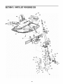
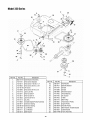
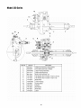
SECTION11: PARTSLISTFORSERIES320
z24
26
48
27
_8
12
25 _
"_"
I
47
13
4O
15
22
Model320 Series
Ref. No.
Part No.
Description
Ref. No.
Part No.
Description
1.
17962
Switch Plate
25.
731-0511
2.
650-0007
Steering Tube Assembly
26.
735-0674
Trim Strip
Floor Pad: LH
3.
683-0033A
Steering Support Bracket
27.
735-0266A
Floor Pad: RH
4.
683-0178A
Front Axle Assembly: RH
28.
736-0105
Bell Washer
5.
683-0179A
710-0224
29.
30.
736-0119
736-0160
Lock Washer
6.
Front AxleAssembly:
Hex Screw AB
7.
710-0459A
710-0643
Hex Screw 3/8-24 x 1.5" Gr.5 Sp.
Lock Screw 5/16-18 x 1.0" Gr.5
31.
32.
736-0169
736-0187
Lock Washer
8.
9.
710-0689
Hex Screw 1/2-13 x 0.75"
33.
736-0196
Flat Washer
10.
710-0837
Oval C-Sunk Screw #10-16 x 0.625"
34.
736-0242
Belleville Washer
11.
710-0958
710-1017
Hex Screw 1/4-20 x 1.25 Gr.5 Sp.
AB Screw 1/4-14 x 0.625"
35.
36.
736-0272
736-0320
Flat Washer
12.
13.
710-1611B
710-3008
37.
38.
736-3078
737-3007
Flat Washer
14.
Self-Tapping Screw 5/16-18 x 0.75"
Hex Screw 5/16-18 x 0.75"
15.
712-0116
Lock Nut 3/8-24
39.
738-0541
Spacer
16.
712-0206
Hex Nut 1/2-13
40.
738-3089A
Steering Adapter
17.
712-0241
Hex Nut
41.
741-0225
Hex Flange Rearing
18.
712-0267
Hex Nut
42.
741-0356
19.
712-0324
Lock Nut 1/4-20
43.
747-0955
20.
712-0411
Lock Nut
44.
748-0290
Bearing: Steering Column
Tie Rod
Pinion Gear
21.
712-0711
Jam Nut
45.
750-0532
Spacer
22.
714-0470
Cotter Pin
46.
783-0411
23.
723-0156
Ball Joint
47.
783-0565C
Gear: Steering Segment
Upper Frame Cover
24.
726-3046
Ratchet Clip
48.
783-1013
Lift Plate
LH
Flat Washer
Flat Washer
Flat Washer
Grease
NOTE: For painted parts, please refer to the list of color codes below. Please add the applicable color code, wherever
needed, to the part number to order a replacement part. For instance, if a part numbered 700-xxxx is painted Yard-Man
Green, the part number to order would be 700-xxxx-0665.
Yard-Man Green: 0665
Yard-Man Yellow: 0674
Powder Black: 0637
23
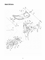
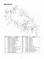
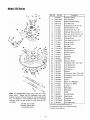
Model320 Series
14
22
44
10
27
J
/
/
f
11
42
52
29
28
28
7
41
12
28
4O
34
40
31
24
_10
40
Model320 Series
Ref. No.
1.
2.
3.
4.
5.
6.
7.
8.
9.
10.
11.
12.
13.
14.
15.
16.
17.
18.
19.
20.
21.
22.
23.
24.
25.
26.
27.
Part No.
Brake Pedal Assembly
683-0161
Shift Cam Assembly
683-0275A
Deck Pedal Assembly
683-0310A
710-1017
Variable Pedal Assembly
Ab Screw 1/4-14 X .625
711-0701
Clevis Pin
711-1156
Shaft
712-0287
Hex Nut 1/4-20
712-0324
Lock Nut 1/4-20
712-3017
Hex Nut 3/8-16
714-0104
Internal Cotter Pin
714-0111
Hairpin Clip
714-0470
720-0166
Hairpin Clip
Ball Knob
726-0100
Push Cap
726-0450
Plug Cap
731-0405
Snap-on Bushing
731-1913
Ref. No.
Description
683-0155A
28.
29.
30.
31.
32.
33.
34.
35.
36.
37.
38.
39.
40.
41.
42.
43.
44.
45.
46.
47.
48.
49.
50.
51.
52.
53.
Stop Lever
732-0815A
Extension Spring
732-0865
735-o261
Torsion Spring
Drive Pad
735-0262
Deck Pad
735-0263
Brake Pad
736-0117
Flat Washer 3/8 X .620 X .033
736-0133
Flat Washer.411 x 1.25" x .100
736-0159
5/16 Washer
736-0169
Lock Washer
Part No.
Description
736-0187
736-0262
Flat Washer
Flat Washer
736-0272
Flat Washer.510
736-0300
Flat Washer
736-O329
Lock Washer
736-0608
Spring Washer
736-3000
Flat Washer
736-3019
Flat Washer
,531 X 1.062 X ,134
736-3020
Flat Washer
,271 X ,630 X .o65
738-0255
Shoulder
Screw
738-0373
Shoulder
Screw
738-0974
Shoulder Screw .375 X ,380 X 1/4-20
741-0591
Flange
746-0935A
Shift Cable
746-0936
Variable
746-0937
Brake Cable
746-0940
Deck Cable
746-0964
Throttle
747-0963A
Brake Rod
747-0964
Brake Lock Out Rod
750-0736
Shoulder
783-0473
Brake Lock Out Bracket
783-0525
Self-Propelled
783-0593A
Shift Lever
783-0794
Bracket:
726-0157
Cable Tie
X 1.oo X .o60
,375 Dia X .18
Bearing
Drive Cable
Choke Cable: 67"
Spacer
Pedal Link
Lock-Out
Pedal
NOTE: For painted parts, please refer to the list of color codes below. Please add the applicable color code, wherever
needed, to the part number to order a replacement part. For instance, if a part numbered 700-xxxx is painted Yard-Man
Green, the part number to order would be 700-xxxx-0665.
Yard-Man Green: 0665
Yard-Man Yellow: 0674
Powder Black: 0637
25
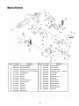
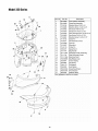
Model320 Series
22
27
5
16
3
26
6
29
21
0
13
2
21
17
24
20
9
Ref. No.
Part No.
Description
Ref. No.
Part No.
Description
1.
2.
683-0152
683-0194A
Pivot Link Assembly
Lift Arm Assembly
16.
17.
732-0829
732-0837
Extension Spring
Torsion Spring
3.
4.
710-0376
Hex Screw 5/16-18 X 1.00 Gr.5
18.
736-0119
710-3230
Hex Bolt 1/2-13 X 2.75 Gr.5 Spec.
19.
736-0140
Lock Washer 5/16
Flat Washer .385 LD. x .620 O.D.
5.
6.
711-0332
Lift Bracket Pin
20.
736-0169
711-1120
7.
8.
711-3319
712-0266
Lift Rod
Ferrule
Jam Nut
21.
22.
23.
736-0257
736-0275
736-3019
9.
10.
712-3008
Jam Nut 3/8-16 Gr. 5
24.
738-0145
712-3010
Hex Nut 5/16-16
25.
738-0183
Shoulder Screw
Shoulder Screw
11.
12.
13.
14.
712-3048
Jam Nut
26.
738-0958
Shoulder Spacer
714-0104
Cotter Pin
27.
783-0435
714-0147
28.
29.
783-0437
783-0440
Upper Deck Link
Axle Bracket: Rear
714-3010
Cotter Pin
Cotter Pin
15.
720-0298
Handle Grip
26
Lock Washer
Flat Washer
Flat Washer 5/16
Flat Washer
_ower Link
15
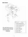
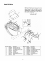
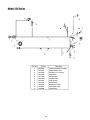
Model320 Series
lO
11
5
13
1
2
Ref.
No.
2
NOTE: For painted parts, please refer to the list of
color codes below. _lease add the applicable color
code. wherever needed, to the part number to order a
replacement part. For instance, if a part numbered
700-xxxx is painted Yard-Man Green. the part number
to order would be 700-xxxx-0665.
Yard-Man Green: 0665
Yard-Man Yellow: 0674
Powder Black: 0637
27
Part No.
Description
1
629-0865
Harness Assembly Adapter
2
710-1208
Hex TT Screw 5/16-18 x 3.50
3
4
710-0227
Hex Washer Head Self-Tap.Scew
710-0805
Hex Screw 5/16q 8 x 1.5 Gr. 5
5
6
710-0642
Thd. Forming Scr. 1/4-20x .75
712-3010
Hex Nut 5/16-18
7
714-0115
Cotter Pin
8
726-0320
Insulator Nut Plate
9
10
736-0289
Shoulder Bushing
736-0119
Lock Washer 5/16
11
736-3000
Fiat Washer
12
750-1064
Spacer
13
783-0591
Tranaaxle Bracket
14
783-0433A
Shift Lever
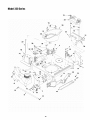
Model320 Series
2
\\\
15_
32
26
13
J
lO
17
23
12
31
25
24
11
26
7
@
15
9
4_
Ref. No.
Part No,
1
2
3
4
5.
6.
7
8.
9.
10.
11.
12.
683-0147A
717-0884
Variable Speed Pulley Assembly
13.
14.
15.
16.
17.
732- 0814
Extension Spring
732-0815A
736-0169
Extension Spring
Lock Washer
736-0171
Lock Washer
736-0219
Bell Washer
710-0314
Idler Bracket Assembly
Hex Screw (Special)
Hex Screw 7/16-20 x 1.0"
710-0902
Hex Screw 3/8-24 x 3.75"
710-1611B
TT Screw
710-3096
Hex Screw 3/8-16 x 2.0"
712-0116
Jam Lock Nut
712-0241
Hex Nut 3/8-24
712-3017
Hex Nut 3/8-16
712-3035
Jam Nut 9/16-18
714-0114
Sq. Key
710-0191
3
Descript_o_
Ref. No.
28
Part No.
Description
18.
19.
20.
736-0247
Flat Washer
736-0427
Beleville Washer
737-0167
Grease
21.
22.
23.
24.
25.
26.
27.
28.
29.
30.
31.
32.
737-0288
Grease
738-0968
Shoulder Spacer
741-0405
Thrust Bearing
750-0705
754-0453
Slv. Spacer
V-Belt
756-0116
Idler Pulley
756-0650
Transmission Pulley
756-0658
Engine Pulley
756-0981A
Flat Idler Pulley
783-0528
Idler Bracket: Variable Speed
Cable Bracket
783-0529
683-0149B
Frame Assembly
Model320 Series
18
21
30
17
%
15
31
34
3d
33
25
35
28
4
32
R_. No.
Put No.
1
783-0605
3
4
783-0564A
783-0811
5
683-0264A
6
783-0554
8
9
783-0414A
783-0413
10
783-0412B
11
12
Description
Ref. No.
Part No.
Description
Deck Stabilizing Bracket
Front Frame: Upper
20
21
726-0272
725-0157
Clamp: 9/16 dia.
Cable Tie
Steering Gear Cover
22
714-0470
Hairpin Clip
Front Channel Assembly
Cam Bracket
Frame Rail: Rear
23
25
26
714-0147
714-0104
712-0271
Hairpin Clip
Frame RaiI--L.H.
27
712-0265
Frame RaiI--R.H.
28
711-1165
Hex Nut 1/4-20
Clevis Pin
747-0985
736-3019
Deck Rod
29
711-0332
Lift Bracket Pin
Flat Washer .531 X 1.062 X .134
30
710-1611B
TT Screw 5/16-18 x .75
14
736-0275
736-0187
Flat Washer 5/16
Flat Washer .64 I.D. X 1.24 X .06
31
32
710-1017
710-0599
Torx Mach. AB Scr. 1/4-14 x 0.625 _
15
16
736-0101
Flat Washer 3/8 X 1.00 X .030
33
683-0163A
17
735-0271
Rubber Bumper
34
683-0160
Steering Support Bracket
Pivot Bracket Assembly: Hood
18
735-0199A
Rubber Bumper
35
683-0142
Pivot Bar Assembly
19
732-0829
Extension Spring
29
Hairpin Clip
Hex Nut
Hex TT Screw 1/4-20
Model320 Series
13
35
12
23
38
43
5
4
7
45
41
11
41
22
2
25
41
22
3O
3O
Model320 Series
Ref. No.
Part No.
Description
Ref. No.
Part No.
Description
1.
683-0149B
Frame Assembly
25.
731-1682A
Oil Drain Sleeve
2.
683-0190A
Frame Rail Support: RH
26.
731-1945A
Engine Duct
3.
683-0191A
Frame Rail Suppod: LH
27.
732-3080A
4.
683-0192
710-0148
28.
29.
735-0273
736-0119
Compression Spring
Rubber Washer
5.
Muffler Pipe Extension
Hex Fl. Screw #8-32 x 0.375
6.
710-0157
Hex Screw 5/16-24 x .75" Gr.5
30.
736-0123
Flat Washer
7.
710-0599
8.
710-0654A
Self-Tapping Screw
TT Screw 3/8-16 x 1.0"
31.
32.
736-0169
736-0188
Lock Washer
9.
710-0751
Hex Screw 1/4-20 x 0.5"
33.
736-0222
Lock Washer
10.
710-0871
Hex Slot Sems Screw #10-32 x 0.38
34.
736-0329
Lock Washer
11.
710-1237
TT Screw #10-32 x 0.625"
35.
736-0400
Flat Washer
12.
710-1611B
TT Screw 5/16-18 x 0.75"
36.
736-0607
Lock Washer
13.
710-1653
Machine Screw #10-32 x 0.5"
37.
737-0169
14.
710-3008
Hex Screw 5/16-18 x 0.75"
38.
738-0960
Motor Oil
Shoulder Screw
15.
711-0222A
16.
712-0267
Battery Hold-Down Rod
Hex Nut 5/16-18
39.
40.
741-0516
751 B213146
17.
712-0271
Hex Sems Nut 1/4-20
41.
751-0535
18.
712-0291
Lock Nut 1/4-20
42.
751-0656
Fuel Tank
19.
712-0397
20.
712-3017
Wing Nut with Bell Washer
Hex Nut
43.
44.
783-0561
783-0624
Hitch Plate
21.
725-0157
Cable Tie
45.
783-0630C
22.
726-0205
23.
726-02O9
Hose Clamp
Cable Tie
46.
47
783-0809B
725-1698
24.
731-0708
Battery Cover
3
Part No.
\
@
5
\\\\
\\\\
11
10
31
Flat Washer
Flange Bearing
Throttle Casing Clamp
Fuel Line Hose
Battery Bracket
Fuel Tank Bracket
Transaxle Suppor_ Bracket
Battery (not shown)
Description
634-0139
Rear Wheel Cempl.
634-0169A
734-1727
Front Wheel Cempl.
Rear Tire
734-1382
Front Tire
734-0255
Valve: Tubeless Air
737-0211A
Grease Fitting
741-0353
Flange Bearing
634-0138
Rim Assembly
734-1455A
Rim Assembly
Hex Bolt 5/16-24 x .75"
710-0627
6
Lock Washer
736-0242
Beleville Washer
714-0115
Cotter Pin
736-0285
Flat Washer
736-0156
Flat Washer
731-0484A
Hub Cap (not shown)
Model320 Series
NOTE: For painted parts, please refer to the list of color
codes below.
Please add the applicable color code,
wherever
needed, to the part number to oraer a
replacement part. For instance if a part numbered 700xxxx _s paintec Yard-Man Green the part number to
order would be 700-xxxx-0665.
Yard-Man Green: 0665
Yard-Man Yellow: 0674
Powder Black: 0637
16
/
14
\
/.4-'
/
I
3'
Ref. No.
1.
2.
3.
4.
5.
6.
7.
8.
Part No.
710-0599
710-0870
Description
TT Screw 1/4-20 x 0.5
Ref. No.
9.
Pad No.
783-0446
Description
Plate: Hood
TT Screw 3/8-16 x 0.62
10.
783-0447
Hood Bracket
710-1017
720-0238
Torx AB Screw 1/4-14 x 0.625
11.
783-0448
Hood Bracket: Reinforcement
Red End Grip
12.
783-0449A
731-0511
Trim Strip
13.
783-0451A
Hinge Bracket: Rear
Pivot Plate: Rear Hood
73f-f69fA
783-0410
Grass Bag Lens
Bracket Reinforcement:
14.
15.
783-0545
783-0562
783-0445
Hood
16.
757-0364A
"
Hood
32
Hood Screen
Hinge Bracket: Front
Seat
Model320 Series
12
10
9
4
3
11
Ref. No.
Part No.
Description
1.
2.
618-0232
618-0248
Differential Assembly: Single Speed
3.
618-0072B
Upper Housing Assembly
Drive Shaft assembly: LH Brake
Detent Shaft Assembly
4.
5.
6.
,611-0114
661-0006
710-1206
7.
710-1325
8.
717-0678
Hex Washer Hd. TT Screw 1/4-20 x 1.65
Brake Puck
9.
719-0313B
Lower Housing
10.
732-0863
Spring Detent
11.
737-0148
12.
741-0862
Grease
Ball Detent
13.
761-0202
Brake Disc
14.
777-6318
Label
Brake Yoke Assembly: LH
Hex Washer Hd. TT Screw 1/4-20 x2.37 Gr,5
33
Model320 Series
Ref. No,
36
18
4_
28
38
35
39
2O
_10
2
1
%
1
Spindle Assembly
683-0150D
Deck Assembly
3.
683,0159
4.
683-0173
Brake Bracket AssemblY
Deck Belt Cover
5.
6.
710-0134
710_0191
710,0347
Carriage Screw 1/4-20 x .62"
710-0599
Self-Tapp. Screw 1/4-20 x :5"
9.
10.
710_0650
Self-Tapp. Screw 5/16-18 x .75"
710,0672
Hex Cap Scr. 5/16-24 x 1.25'i
11.
Carriage Screw
12.
710-0932
710-1611B
13.
14.
712-0241
712-0287
Hex Nut 3/8-24
712-0397
32
NOTE: For painted parts, please refer to the list of color
codes below.
Please add the applicable color code.
wherever needed, to the part number to order a replacement
part. For instance, if a part numbered 700-xxxx is paEnted
Yard-Man Green. the par_ number to order would be 700xxxx-0665,
Yard-Man Green: 0665
Yard-Man Yellow: 0674
Powder Black: 0637
Hex Screw 3/8-i 6 x 1,75 '!
Terx Screw 5/16-18 x .75"
Hex Nut 1/4-20
712-0417A
Wing Nut t
Flange Nut 5/84 8
712-3017
Hex Nut 3/8-16
17.
18.
712-3057
Hex Nut 5/16-24
714-0115
Cotter Pin
19.
20.
726-0201
Speed Nut
21.
22.
732-0429A
Push Nut
Extension Spring
736-0101
Flat Washer 3/8 x 1.00 x .030"
23.
24.
25.
736-0119
736-0169
Lock Washer 5/16
736-01 Z3
Flat Washers
26.
736-0289
27.
28.
736-0300
Bushing
Flat Washer .406 x .875 x .059"
726,0233
Lock Washer 3/8
736-0343
736-3020
Flat Washer .330 x 1.25 x :120"
738-0968
Spacer
31.
32.
742-0578
Blade: 27.5'! Bagging:l:
742-0651
Three-in-one
33.
34.
747-0957
Link Rod
747-0972
Belt Keeper
35.
36.
747-1172
Belt Keeper
37.
38.
756-0627
783-0463A
Flat Idler Pulley
Idler Bracket
39.
783-0529
Cable Bracket
40.
41.
783-0569B
783-0594
Deck Plate
754-0754
F!at Washer
Blade*
.V Belt
Deck Cable Plate
1" n three-in-one single blade models only
$ Not applicable to three-in-one
m three-in-one
34
Hex Bolt 3/8-24 x 1.25"
15.
16.
29.
30.
31
Description
618-0250
7.
8.
21
Part No.
1.
2.
models only
single blade models
Model320 Series
Ref. No
16
9
23
22
23
25
1
J
23
14
11
20
W
27
Part No.
Description
1
631-0060
2
631-0080
3
710-0166
4
710-0286
5
710-0456
6
710-0564
7
710-0642
8
710-0825
9
710-0924
10
711-0415
11
712-0271
12
712-0298
13
712-0397
14
714-0115
Wing Nut
Cotter
Pin 1
15
726-0271
16
731-1441
17
731-1743A
18
731-1744
19
731-1745A
20
732-0839A
21
732-0841
22
732-0854
23
736-0173
24
736-0329
Speed Nut 1.
Bag Handle
Discharge Chute: Grass Bag
Side-Discharge Chute 1.
Mulching Plug t
BagRelease Lever
Torsion Spring
Clip Spring
FlatWasher
Lock Washer
25
783-0544A
26
783-0575A
27
783-0645
Flow indicator Assembly
Grass Bag Assembly
Machine Screw 1/4-20 x 1.0
Machine Screw 1/4-20 x 0.5"
Hex Screw #10-16 x 0.5"
Hex Screw 1/4-20 x 2.75" 1
Self-Tapping Screw 1/4-20 x 0.75"
Hex Screw 1/4-20 x 3.75" t
Machine Screw 1/4-20 x 0.75"
Clevis Pin
Hex Seres Nut 1/4-20
Jam Nut
Grass Bag Screen
Pivot Bracket
Deflector Plate
1.Only applicable to three-in-one
12
23
24
18
8
35
models
Model320 Series
\
5
10
t
2
m
m
/
'ql_\\\
11
Ref. No.
1.
2.
3.
4.
5.
6.
7.
8.
9.
10.
11.
Part No.
Description
629-0945
Harness
725-0267
Ignition
725-1426
Solenoid:
725-1462
Seat Switch
725-1643
Spring
725-1657A
Interlock
725-1381
Fuse: 20 amp.
725-1726
Battery
Cover
725-3237
Battery
Cover:
729-0357
Fuse Holder
729-0359
Harness
36
Assembly
Switch:
w/o relays
5 Pin
12 V. 100 amp.
Switch
Switch
Clip
Red
w/Clip
9
7
Model320 Series
2
/
Ref.
No.
./
Part No.
Description
1
731-1869
Steering Wheel: 4 Spoke
2
731-1904
Steering Wheel Cap
2
Ref. No.
Part No.
Description
1.
2.
731 -1877
731-1918
Steering Column: Green
Control Knob
3.
4.
712-0142
Hex Nut 8-32
710-3217
Pan Head Machine Screw #8-32
5.
6.
7.
8.
710-0599
Hex Screw TT 1/4-20 x .50"
710-0514
Hex Screw 3/8-16 x 1.0"
712-0431
Lock Nut
749-1099
Bumper Tube*: Front
* If equipped
5
NOTE: For painted parts, please refer to the list of
8 color codes below.
Please add the applicable color
code. wherever needed, to the part number to order a
"eplacement part. For instance if a part numbered 700_J=L_=_
xxxx is painted Yard-Man Green, the part number to
order would be 700-xxxx-0665
Yard-Man Green: 0665
6 _-J
Yard-Man Yellow: 0674
Powder Black: 0637
37
Safety& DecorativeLabels
777120125
777120378
777120489
777[
777D02423
777S30199
FACING OPERATOR
777S30145
777D02307
RIGHT SIDE
777D02308
_
_
777120379
777D04285
777CX00001
777120808
777S30503
777S30200
38
_IODEL PLATE
ON RIGHT SiDE
YourNotes
Date
Comments
39
MANUFACTURER'S
LIMITED WARRANTY
FOR:
YaRD-MaN)//
The limited warranty set forth below is given by MTD LLC with
respect to new merchandise purchased and used in the
United States, its possessions and territories.
MTD LLC warrants this product against defects for a period of
two (2) years commencing on the date of original purchase
and will, at its option, repair or replace, free of charge, any
part found to be defective in materials or workmanship. This
limited warranty shall only apply if this product has been
operated and maintained in accordance with the Operator's
Manual furnished with the product, and has not been subject
to misuse, abuse, commercial use, neglect, accident,
improper maintenance, alteration, vandalism, theft, fire,
water, or damage because of other peril or natural disaster.
Damage resulting from the installation or use of any
accessory or attachment not approved by MTD LLC for use
with the product(s) covered by this manual will void your
warranty as to any resulting damage.
Normal wear parts or components thereof are subject to
separate terms as follows: All normal wear parts or
component failures will be covered on the product for a period
of 90 days regardless of cause. After 90 days, but within the
two year period, normal wear part failures will be covered
ONLY IF caused by defects in materials or workmanship of
OTHER component parts. Normal wear parts and
components include, but are not limited to: batteries, belts,
blades, blade adapters, grass bags, rider deck wheels, seats,
snow thrower skid shoes, shave plates, auger spiral rubber,
and tires.
HOW TO OBTAIN SERVICE: Warranty service is available,
WiTH PROOF OF PURCHASE, through your local authorized
service dealer. To locate the dealer in your area, check your
Yellow Pages, or contact MTD LLC at P.O. Box 361131,
Cleveland, Ohio 44136-0019, or call 1-800-800-7310 or log
on to our Web site at www.mtdprnducts.com.
This limited warranty does not provide coverage in the
following cases:
a.
b.
c.
The engine or component parts thereof. These items
carry a separate manufacturer's warranty. Refer to
applicable manufacturer's warranty for terms and
conditions.
Log splitter pumps, valves, and cylinders have a sepa
rate one year warranty.
Routine maintenance items such as lubricants, filters,
blade sharpening, tune-ups, brake adjustments, clutch
adjustments, deck adjustments, and normal
deterioration of the exterior finish due to use or
exposure.
d.
e.
f.
g.
MTD LLC does not extend any warranty for products
sold or exported outside of the United States, its
possesions and territories, except those sold through
MTD LLC's authorized channels of export distribution.
Parts that are not genuine MTD parts are not covered
by this warranty.
Service completed by someone other than an
authorized service dealer is not covered by this
warranty.
Transportation charges and service calls are not
covered.
No implied warranty, including any implied warranty of
merchantability of fitness for a particular purpose,
applies after the applicable period of express written
warranty above as to the parts as identified. No other
express warranty, whether written or oral, except as
mentioned above, given by any person or entity,
including a dealer or retailer, with respect to any product,
shall bind MTD LLC. During the period of the warranty,
the exclusive remedy is repair or replacement of the
product as set forth above.
The provisions as set forth in this warranty provide the
sole and exclusive remedy arising from the sale. MTD
LLC shall not be liable for incidental or consequential
loss or damage including, without limitation, expenses
incurred for substitute or replacement lawn care services
or for rental expenses to temporarily replace a warranted
product.
Some states do not allow the exclusion or limitation of
incidental or consequential damages, or limitations on how
long an implied warranty lasts, so the above exclusions or
limitations may not apply to you.
In no event shall recovery of any kind be greater than the
amount of the purchase price ofthe product sold. Alteration
of safety features of the product shall void this warranty.
You assume the risk and liability for loss, damage, or injury to
you and your property and/or to others and their property
arising out of the misuse or inability to use the product.
This limited warranty shall not extend to anyone other than the
original purchaser or to the person for whom it was purchased
as a gift.
HOW STATE LAW RELATES TO THIS WARRANTY:
This
limited warranty gives you specific legal rights, and you may
also have other rights which vary from state to state.
MTD LLC, P.O. BOX361131CLEVELAND,OHIO44136-0019; Phone:1-800-800-7310