1
TH200E
High-Speed Thermal Printer
User Guide
Edition July 2008
All brands and product names mentioned in this document are
trademarks of their respective owners.
The reproduction, transmission or use of this document or its contents is
not permitted without express authority. Offenders will be liable for
damages. All rights, including rights created by patent grant or
registration of a utility model or design, are reserved.
Delivery subject to availability. Features and specifications described
are subject to change without notice.
Copyright @ Wincor Nixdorf Pte Ltd.
TH200E User Guide
Contents
Manufacturer’s Certification
1
Warranty
1
General Safety Information
2
Overview Of The Printer
3
Features
4
Installing The Printer
5
Unpacking And Checking The Printer
Choose A Location
Connecting Cables
5
5
6
Loading Receipt Paper
7
Adjusting Paper Roll Guide
Adjusting Paper-Near-End Sensor
Loading Paper
7
8
8
The Operator Control Panel
9
Status/Error LED
9
Autocutter
10
Configuring The Printer
11
Configuration Menu
Example Menu
Duty Cycle Restrictions
12
13
13
Care Of The Printer
14
Cleaning The Print Head
Cleaning Paper-End/Paper-Near-End Sensors
Cleaning The Platen Roller
14
14
14
Appendix
15
Technical Data
Interface Connectors
Drawer Kick Out Connector
Power Supply Connector
Serial Port Connector
Ethernet Port Connector
USB Connector Type ‘B’
Parallel Port Connector (IEEE 1284-B)
Control Sequences
15
16
16
16
16
16
17
17
18
TH200E User Guide
Manufacturer’s Certification
The device complies with the requirements of the EEC directives
89/336/EEC with regard to “Electromagnetic Compatibility” and tested
to safety according to CE requirements.
You will find the CE mark on the device or packaging.
Warranty
Wincor Nixdorf guarantees a limited warranty engagement for 12 months beginning
with the date of delivery. This warranty engagement covers all damages which
occur during normal use of the product.
Damages due to:
improper or insufficient maintenance,
improper use of the product or unauthorized modifications of the product,
inadequate location or surrounding,
will not be covered by the warranty.
All parts of the product which are subject to wear and tear such as the
printhead or the cutter are not included in the warranty engagement.
Please order original spare parts from Wincor Nixdorf customer service center.
1
TH200E User Guide
General Safety Information
Please read the following items carefully before installing & using the printer.
Safety Instructions
Do not touch the printhead, it is hot and sensitive to ESD
(Electrostatic discharge)!
Do not touch the cutter and tear bar of the printer.
CAUTION:
Install the printer on a flat and stable surface.
If the printer is brought in from a cold environment, dewfall condensation
can occur. In case of such condensation, do not turn on the power until
the printer is completely dry.
Use a properly grounded power supply outlet. To disconnect the printer
from the power supply, switch off the printer first then disconnect the
power supply plug.
Always shut down the printer when plugging or unplugging interface
connectors to avoid damage to the controller board. Never plug or unplug
the interface connectors during thunderstorms.
Make sure that no objects (e. g. paper clips) or liquids get inside the
printer as they might cause electric shocks or short circuits.
Protect the printer from vibration, dust, moisture, heat and liquids.
Do not allow printing without paper rolls installed as it may cause damage
to the print head.
Use only certified power supplies and cables.
The printer should only be transported in its original packaging to protect
against damages from knocks and bumps.
The printer should be repaired by authorized personnel only.
Repairs made by an unauthorized service provider not only
could jeopardize the safety of the user, but could also lead to
the cancellation of all warranty and liability agreements.
2
TH200E User Guide
Overview Of The Printer
The TH200E thermal printer is a high-performance printer that is fast, quiet and
reliable, yet easy to use. The printer is compact and will fit anywhere. Paper loading
is simple with drop-in paper roll. It also comes with a cutter and cash drawer
connections. With these convenient features, the TH200E is an essential
supplement to you point-of-sale system!
3
TH200E User Guide
Features
Print Speed
150mm/s Maximum
Resident Character Sets
PC437 (US), PC850, PC860, PC863, PC865,
PC852,PC858, WPC1252, PC866, Katakana, Thai
(Standard English/Thai model)
(Actual resident character sets may be different in
other printer models)
Others Languages
Simplified Chinese, Traditional Chinese, Korean,
Japanese, Hong Kong, Vietnamese
Integrated Bar Codes
Code 39, UPC-A, UPC-E, EAN-8, EAN-13, Codabar,
Code 128
Printer Resolution
203dpi×180dpi(dots/inch)
Print Width
80mm, 640 Dot Positions
Configuration
Use FEED Button Menu
Flash Memory (Firmware)
1MB/2MB/4MB (model specific)
Flash Memory (Font/Logo)
64KB to 256KB (model specific)
Autocutter
Full Cut or Partial Cut
Interface Options
RS232C, Bi-Directional Parallel, USB 1.1, Ethernet
(10 BASE-T)
Cash Drawer
Drive 1 or 2 Cash Drawers
Sensors
Cover Open, Paper-Near-End, Paper-End
Paper Roll Width
82.5mm/80mm/76mm/69.5mm/57.5mm selectable
Max Paper Roll Diameter
83mm
Others
Wall Mount
Buzzer,
Adjustable Paper-Near-End Sensor,
Mark Sensor (certain models only)
Optional- Wall Mount Kit
Colors
Light Grey, Black
4
TH200E User Guide
Installing The Printer
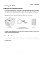
Unpacking And Checking The Printer
Unpack the printer and see if the contents of the box matches the packing list. If any
damage has occurred in transit, or if there is any discrepancy between the contents
and the packing list, please inform your supplier or Wincor Nixdorf’s representative.
Packing List: Printer, Communication Cable, Paper Roll, User Guide
TH200E Printer
Communication Cable
(Actual cable depending on interface)
Paper Roll
Keep the original packaging in case you need to transport the printer in the future to
protect against knocks and bumps.
Choose A Location
Set up the printer on a flat surface where it will not be exposed to extreme
environmental conditions such as vibrations, dust, moisture, heat and strong
magnetic fields.
5
TH200E User Guide
Connecting Cables
The cables must be connected before plugging in the power cable. Turn off the host
computer, if necessary.
1
Plug in the communication cable. Secure the cable by tightening the two screws
(for serial interface).
2
Plug in the cash drawer cable. The connector allows connection for one or two
cash drawers. (use a “Y” cord for two drawers).
3
Finally plug in the 24V power cable for the printer.
Note:
When using an external power adapter, connect the adapter to an appropriate
grounding outlet. Do not connect the Hosiden plug when the host computer is
turned on, this can lead to an automatic reboot of the system.
If the power supply current can only provide 2A or less, use the configuration menu
to select LOW POWER MODE.
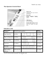
Depending on the interface the connector panel may vary from the below
illustration.
Back View
Power Supply
Communication Cash Drawer
Connector
Connector
Connector (Hosiden Plug)
6
TH200E User Guide
Loading Receipt Paper
Open the printer top cover by pulling the cover release lever.
Adjusting Paper Roll Guide
The printer can easily accommodate different paper roll widths by adjusting the
position of the paper roll guide.
Locate the paper roll guide on the right hand side of the paper cabin. Press at the top
of the paper roll guide and take it out. Drop in the paper roll. Snap in the paper roll
guide into one of the four guiding locations, depending on the width of the paper roll.
Removing the paper roll guide completely allows paper roll width of 82.5mm.
Check that the paper roll can rotate freely.
During configuration, use the menu to adjust the corresponding paper roll width and
margins for printing. The default paper roll width is 80.0mm.
Press down to release
guide from paper cabin
Paper Roll Guide
7
TH200E User Guide
Adjusting Paper-Near-End Sensor
The printer is equipped with a paper-near-end sensor to alert the user when the paper
is running low. The amount of paper remaining can be adjusted by using the
adjustment lever. The adjustable paper roll diameter range from 22mm to 34mm
approximately.
Max Detectable
Roll Diameter
Maximum
Min Detectable
Roll Diameter
Minimum
Core
Adjusting Paper-Near-End
Loading Paper
Note: The paper must not be attached at the core. Use paper with colour stripe at the
end to indicate that the paper is running low.
8
TH200E User Guide
The Operator Control Panel
Power LED
Continuous green light indicates
POWER ON.
Error LED
Indicates status/error conditions
through
different
blinking
patterns.
FEED Button
Press to feed paper.
Pressing FEED button for a few
seconds while switching on the
power will enable the printer
menu.
Status/Error LED
Status / Error
Condition
ERR LED flashing pattern
Beeper
(If enabled)
Paper-Near-End
One Blink
One beep
Paper Out/Paper-End Two Blinks
Two beeps
Top Cover Open
Three Blinks
Three beeps
Cutter Error
Four Blinks
Four beeps
Print Head
Continuous Blink
Temperature Too High
Five beeps
Print Head Voltage/
Supply Voltage
Abnormal
Five beeps
Continuous ON
The LED will also blink during Self-Test standby mode.
9
TH200E User Guide
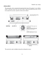
Autocutter
The autocutter unit is conveniently located at the front of the printer. In an unlikely
case of cutter jam where you are not be able to open the printer top cover, do not
force open the top cover, open the cutter cover instead.
Cutter extending out and not at home
position.
Cutter at home position.
The autocutter can be disabled using the configuration menu.
10
TH200E User Guide
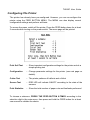
Configuring The Printer
The printer has already been pre-configured. However, you can re-configure the
printer using the FEED BUTTON MENU. The MENU can also display current
configuration settings and perform self-tests.
To access the menu, switch off the printer. Press the FEED button down for at least
2 seconds while turning on the power switch. The menu page will be printed:
Print Self Test
– Show important configuration settings for the printer and do a
simple printing test
Configuration
– Change parameter settings for the printer. (see next page for
details)
Cutter Test
– The printer performs 4 halfcuts and a fullcut
Sensor Test
– ERR LED will indicate ON/OFF according to the state of the
sensors
Print Statistics
– Show the total number of paper cuts and linefeeds performed
To choose a submenu, PRESS THE FEED BUTTON X-TIMES according to the
selection digit in the main menu, then press and hold the FEED button for at least
one second to validate the choice.
11
TH200E User Guide
Configuration Menu
Below settings are available in the configuration menu. Use this menu to
enable/disable certain functions and to configure the printer.
Use the FEED button to navigate to the respective sub-menu.
Configuration Menu Settings
Communication
(Serial)
Baud Rate
Parity
Data Bits
Stop Bits
Handshaking
Rx Buff Size
Data Receive Error Setting
Mechanism and Hardware
Mark Sensor (specific models only)
Cutter
Buzzer
Power Supply
Print Setting
Darkness Settings
Paper Roll Width
Left Margin
Right Margin
CR Command
Code Page
Paper Sensor Settings
PAPER LOW Alarm
Stop Print when PAPER LOW
Set Default Configuration
Set printer to default configurations
To save your new settings, select Exit with Save on the configuration main menu. Use
Self-Test printout to verify your new settings.
Note: contents of the submenu might change depending on firmware version.
12
TH200E User Guide
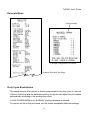
Example Menu
Current setting
Example Configuration Sub-Menu
Example Print Self Test Page
Duty Cycle Restrictions
The supply current of the printer is directly proportional to the duty cycle (ie, amount
of black of printing) and the darkness printing, the printer will adjust the print speed
automatically according to the printing duty cycle.
In LOW POWER MODE only “NORMAL” printing darkness is allowed.
To improve the life of the print head, use the lowest acceptable darkness settings.
13
TH200E User Guide
Care Of The Printer
Remove any paper cuttings or foreign objects from the paper cabin to ensure
smooth operation of the paper roll.
Clean your printer at regular intervals with a commercially available cleaner for
sensitive surfaces (alcohol solvent is recommended). Never use acidic solvents.
Carefully clean the cutter area to remove paper dust.
Before cleaning make sure that the power is switched off, the power
supply plug is disconnected and that no moisture gets into the printer.
Cleaning The Print Head
The printhead should be cleaned, when the printout becomes lighter or there are
vertical columns on the printout. Before cleaning, let the printhead cool down first by
turning off the power. (The thermal print head is very sensitive to scratches. Clean
the head using only non-abrasive cloth & alcohol solvent.)
Cleaning Paper-End/Paper-Near-End Sensors
When any of the sensors behave abnormally, wipe the sensor using a soft cloth and
alcohol solvent.
Cleaning The Platen Roller
When there are paper misfeeds or the roller is dirty, please clean the platen roller.
Wipe off any stains or dust from the roller.
CAUTION: Never use any sharp object like screw driver as a cleaning tool. This will
damage the printer.
Paper-Near-End Sensor
Platen Roller
14
TH200E User Guide
Appendix
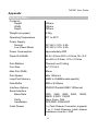
Technical Data
Footprint:
Height
Width
Depth
145mm
146mm
190mm
Weight (w/o paper)
2.3Kg
Operating Temperature
5℃ to 40℃
Power Supply:
Normal
Low Power Mode
DC 24V+/-10%, 2.5A
DC 24V+/-10%, 2.0A
Power Consumption
Approximately 60W
Paper Roll Width
82.5+/-0.5mm,80.5+/-0.5mm,76+/-0.5
mm,69.5+/-0.5mm. 57.5+/-0.5mm
Print Method
Thermal Line Printing
Font Size
9×17/12×24
Max Print Width
80mm
Print Speed
Max 150mm/s
Logo/Font Memory
64KB to 256KB(model specific)
Data Buffer
4KB or 45 Bytes
Interface Options
RS232C/Parallel/USB1.1/Ethernet
Serial Interface
Baud Rate
Parity
Handshake
Cash Drawer
1200, 2400, 4800, 9600, 19200,
38400, 57600, 115200
None, Even, Odd
DTR/DSR, XON/XOFF
1 x Cash Drawer Connector, supports
1 or 2 Cash Drawers (cash drawer
resistance must be > 24Ω
15
TH200E User Guide
Recommended Paper Thickness
≤75µm
Interface Connectors
Drawer Kick Out Connector
Pin Number
Signal Name
Frame Ground
Drive for cash drawer 1
Drawer open/close signal
+24V DC
Driver for cash drawer 2
Signal Ground
1
2
3
4
5
6
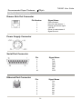
Power Supply Connector
Serial Port Connector
Ethernet Port Connector
Pin
Signal Name
1
2
3
4
6
7
20
FG
TxD
RxD
RTS
DSR
SG
DTR
Pin
Signal Name
1
2
3
4
5
6
7
8
TX+
TXRX+
NC
NC
RXNC
NC
16
TH200E User Guide
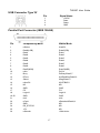
USB Connector Type ‘B’
Pin
Signal Name
1
2
3
4
+5VDC
DataData+
GND
Parallel Port Connector (IEEE 1284-B)
Pin
Compatibility Mode
Nibble Mode
1
nStrobe
HostClk
2
Data0(LSB)
Data0(LSB)
3
Data1
Data1
4
Data2
Data2
5
Data3
Data3
6
Data4
Data4
7
Data5
Data5
8
Data6
Data6
9
Data7(MSB)
Data7(MSB)
10
nAck
PtrClk
11
Busy
PtrBusy/Data3,7
12
PError
AckDataReq/Data2,6
13
Select
Xflag/Data1,5
14
nAutoFd
HOSTBUSY
15
NC
ND
16
GND
GND
17
FG
FG
18
Logic-H
Logic-H
19-30
GND
GND
31
nlnit
nlnit
32
nFault
nDataAvail/Data0,4
33
GND
ND
34
DK_STATUS
ND
35
+5V
ND
36
nSelectln
1284-Active
17
TH200E User Guide
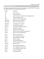
Control Sequences
The control sequences of the printer controller are based on the ECS/POSTM standard.
For details, please refer to the programming manual.
Code
Function
HT
Horizontal tab
LF
Print and line feed
FF
Print and return to standard mode (in page mode)
CR
Print and carriage return
CAN
Cancel print data in page mode
DLE EOT
Real-time status transmission
DLE ENQ
Real-time request to printer
DLE DC4
Generate pulse at real-time
ESC FF
Print data in page mode
ESC SP
Set right-side character spacing
ESC !
Select print mode(s)
ESC $
Set absolute print position
ESC %
Select/cancel user-defined character set
ESC &
Define user-defined characters
ESC*
Select bit-image mode
ESC-n
Turn underline mode on/off
ESC 2
Select default line spacing
ESC 3
Set line spacing
ESC =
Select peripheral device
ESC ?
Cancel user-defined characters
ESC @
Initialize printer
ESC D
Set horizontal tab positions
ESC E
Turn emphasized mode on/off
ESC G
Turn double-strike mode on/off
ESC J
Print and feed paper
ESC L
Select page mode
18
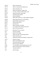
TH200E User Guide
ESC M
Select character font
ESC R
Select an international character set
ESC S
Select standard mode
ESC T
Select print direction in page mode
ESCV
Turn 90º clockwise rotation mode on/off
ESC W
Set printing area in page mode
ESC \
Set relative print position
ESC a
Select justification
ESCc3
Select paper sensor(s) to output paper-end signals
ESCc4
Select paper sensor(s) to stop printing
ESCc5
Enable/disable panel buttons
ESC d
Print and feed n lines
ESC p
General pulse
ESC t
Select character code table
ESC {
Turn upside-down printing mode on/off
FS g 1
Write to NV user memory
FS g 2
Read from NV user memory
FS p
Print NV bit image
FS q
Define NV bit image
Gs FF
Feed next mark to the printing position
GS !
Select character size
GS$
Set absolute vertical print position in page mode
GS (A
Execute test print
GS*
Define downloaded bit image
GS/
Print downloaded bit image
GS:
Start/end macro definition
GS B
Turn white/black reverse printing mode on/off
GS H
Select printing position of HRI characters
GS I
Transmit printer ID
GS L
Set left margin
19
TH200E User Guide
GS P
Set horizontal and vertical motion units
GSV
Select cut mode and cut paper
GSW
Set printing area width
GS\
Set relative vertical print position in page mode
GS ^
Execute macro
GS a
Enable/disable Automatic Status Back (ASB)
GS f
Select font for HRI characters
GS h
Set bar code height
GS k
Print bar code
GS r
Transmit status
GS v 0
Print raster bit image
G8 w
Set par code width
FS !
Set print mode(s) for Kanji characters
FS &
Select Kanji character mode
Fe -
Turn underline mode on/off for Kanji characters
FS .
Cancel Kanji character mode
FS 2
Define user-defined Kanji characters
FS C
Select Kanji character code system
FS S
Set Kanji character spacing
FS W
Turn quadruple-size mode on/off for Kanji characters
20