1
Operator's
Manual
®
14 iN. ABRASIVE CHOP SAW
Model No. 137.375630
C
US
CAUTION:
Before using this Chop Saw,
read this manual and follow
all its Safety Rules and
Operating Instructions
Customer
Help Line
For Technical
Support
1-800-843-1682
•
•
Safety Instructions
Installation
•
•
•
Operation
Maintenance
Parts List
O
Espa_ol, p. 29
Sears Parts &
Repair Center
1-800-488-1222
Sears Brands Management
Corporation
Hoffman
Estates,
See the full line of Craftsman ® products at craftsman.corn
Click on the Craftsman Club ® link and join today!
Part No. 137.375630001
IL 60179
USA
Printed in China
SECTION
Warranty ...................................................................................................
Product Specifications ..............................................................................
Symbols .....................................................................................................
Power Tool Safety .....................................................................................
Chop Saw Safety ......................................................................................
Electrical Requirements and Safety ..........................................................
Tools Needed for Assembly ......................................................................
Carton Contents ........................................................................................
Know Your Chop Saw ...............................................................................
Assembly ..................................................................................................
Adjustments ..............................................................................................
Operation ..................................................................................................
Maintenance .............................................................................................
Troubleshooting Guide .............................................................................
Parts List ...................................................................................................
Repair Protection Agreements ..................................................................
CRAFTSMAN
ONE YEAR
PAGE
2
3
4
5
7
12
14
14
15
16
18
20
22
23
24
27
FULL WARRANTY
FOR ONE YEAR from the date of purchase, this product is warranted against
defects in material or workmanship. A defective product will receive free repair
or replacement if repair is unavailable. For warranty coverage details or to
obtain free repair or replacement, visit the web site: www.craftsman.com
This warranty does not cover the blade, which is an expendable part that can
wear out from normal use within the warranty period. This warranty is void if
this product is ever used while providing commercial services or if rented to
another person. This warranty gives you specific legal rights, and you may
also have other rights which vary from state to state.
Sears Brands Management Corporation, Hoffman Estates, IL 60179
,A WARNING
]
Some dust created by power sanding, sawing, grinding, drilling and other
construction
activities contains chemicals known to the state of California
to cause cancer, birth defects or other reproductive harm. Some examples
of these chemicals are:
o Lead from lead-based paints,
o Crystalline silica from bricks and cement and other masonry products, and
e Arsenic and chromium from chemically-treated
lumber.
Your risk from these exposures varies, depending on how often you do this
type of work. To reduce your exposure to these chemicals: work in a well
ventilated area, and work with approved safety equipment, such as those
dust masks that are specially designed to filter out microscopic
particles.
2012/12
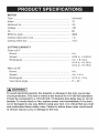
MOTOR
Type ......................................................................................
Universal
Amps .....................................................................................
15
Maximum hp .........................................................................
3.5
Voltage ..................................................................................
Hz .........................................................................................
120
60
RPM (no load) .......................................................................
3600
Cutting wheel arbor size .......................................................
1 in.
Cutting wheel size .................................................................
14 in.
CUTTING CAPACITY
Cross cut 0 °
Round ................................................................................
5 in.
Square ...............................................................................
4-3/4 in. x 4-3/4 in.
Rectangular ........................................................................
3 in. x 8-1/4 in.
4-1/4 in. x 6-1/8 in.
4-1/2 in. x 5-1/8 in.
Miter cut 45 °
Round ................................................................................
4 in.
Square ...............................................................................
4 in. x 4 in.
Rectangular ........................................................................
3-1/3 in. x 5 in.
Vise clamp angle ................................................................
0 ° ~ 45 o
IA WARNING
1
To avoid electrical hazards, fire hazards or damage to the tooJ, use proper
circuit protection. This tool is wired at the factory for 110-120 Volt operation°
it must be connected to a 110-120 Volt/15 Ampere time delay fuse or circuit
breaker° To avoid shock or fire, replace power cord immediately if it is worn,
cut or damaged in any way. Before using your tool, it is critical that you read
and understand these safety rules. Failure to follow these rules could result
in serious injury to you or damage to the tool
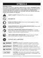
WARNINGiCONS
Your power tool and its Operator's
(a picture symbol intended to alert
a potentially hazardous condition).
symbols will help you operate your
some of the symbols you may see.
Manual may contain "WARNING iCONS"
you to, and/or instruct you how to avoid,
Understanding
and heeding these
tool better and safer. Shown below are
SAFETY ALERT: Precautions that involve your safety.
PROHIBITION
WEAR EYE PROTECTION:
glasses with side shields,
Always wear safety goggles or safety
WEAR RESPIRATORY AND HEARING PROTECTION:
respiratory and hearing protection.
Always wear
READ AND UNDERSTAND OPERATOR'S MANUAL: To reduce
the risk of injury, user and all bystanders must read and understand
Operator's manual before using this product.
KEEP HANDS AWAY FROM BLADE: Failure to keep your hands
away from the blade will result in serious personal injury.
SUPPORT AND CLAMP WORK
DANGER: indicates an imminently hazardous situation
[A DANGER
1 which,
if not avoided, will result in death or serious injury.
indicates
IA WARNING
1 WARNING:
which, if not avoided,
a potentially hazardous situation
could result in death or serious injury.
indicates a potentially hazardous situation which,
IA CAUTION
1 CAUTION:
if not avoided, may result in minor or moderate injury.
I CAUTION
i
CAUTION: used without the safety alert symbol indicates
a potentially hazardous situation which, if not avoided, may
result in property damage.
GENERAL SAFETY INSTRUCTIONS
BEFORE USING THIS POWER TOOL
8.
Safety is a combination of common
sense, staying alert and knowing how
to use your power tool.
,
CAUTION
To avoid mistakes that could cause
serious injury, do not plug the tool in
until you have read and understood
the following.
,
,
,
,
,
,
,
DO NOT FORCE THE TOOL. It will
do the job better and safer at the
rate for which it was designed,
USE THE RIGHT TOOL. Do not
force the tool or an attachment
to do a job for which it was not
designed.
10. USE PROPER EXTENSION
CORDS. Make sure your extension
cord is in good condition. When
using an extension cord, be sure
to use one heavy enough to carry
the current your product will draw.
An undersized cord will result in a
drop in line voltage and in loss of
power which will cause the tool to
overheat. If in doubt, use the next
heavier gauge. The smaller the
gauge number, the heavier the cord.
READ and become familiar
with the entire Operator's
Manual. LEARN the tool's
application, limitations and
possible hazards.
KEEP GUARDS IN PLACE and in
working order.
REMOVE ADJUSTING KEYS
AND WRENCHES. Form the habit
of checking to see that keys and
adjusting wrenches are removed
from the tool before turning ON.
11. WEAR PROPER APPAREL. Do
not wear loose clothing, gloves,
neckties, rings, bracelets or other
jewelry which may get caught in
moving parts. Nonslip footwear is
recommended. Wear protective
hair covering to contain long hair.
KEEP WORK AREA CLEAN.
Cluttered areas and benches invite
accidents,
12. _
ALWAYS WEAR EYE
PROTECTION. Any
power tool can throw
foreign objects into the
eyes and could cause permanent
eye damage. ALWAYS wear Safety
Goggles (not glasses) that comply
with ANSI Safety standard Z87.1.
Everyday eyeglasses have only
impact-resistant lenses. They
ARE NOT safety glasses. Safety
Goggles are available at Sears.
NOTE: Glasses or goggles not in
compliance with ANSI Z87.1 could
seriously injure you when they
break.
U
DO NOT USE IN DANGEROUS
ENVIRONMENTS. Do not use
power tools in damp locations, or
expose them to rain or snow, Keep
work area well lit.
KEEP CHILDREN AWAY. All
visitors and bystanders should be
kept a safe distance from work
area.
MAKE WORKSHOP CHILD
PROOF with padlocks, master
switches or by removing starter
keys.
5
;,
13.
14.
WEARA FACE
MASK
OR DUST MASK. Sawing
operation produces dust.
SECURE WORK. Use
clamps or a vise to hold
work when practical. It
is safer than using your
hand and it frees both hands to
operate the tool.
15. DISCONNECT TOOLS FROM
POWER SOURCE before servicing,
and when changing accessories
such as blades, bits and cutters.
16. REDUCE THE RISK OF
UNINTENTIONAL STARTING.
Make sure switch is in the OFF
position before plugging the tool in.
17. USE RECOMMENDED
ACCESSORIES. Consult
this Operator's Manual for
recommended accessories. The use
of improper accessories may cause
risk of injury to yourself or others.
18. NEVER STAND ON THE TOOL,
Serious injury could occur if the
tool is tipped or if the cutting tool is
unintentionally contacted.
19. CHECK FOR DAMAGED PARTS.
Before further use of the tool, a
guard or other part that is damaged
should be carefully checked to
determine that it will operate
properly and perform its intended
function - check for alignment of
moving parts, binding of moving
parts, breakage of parts, mounting
and any other conditions that may
affect its operation. A guard or
other part that is damaged should
be properly repaired or replaced.
20. NEVER LEAVE THE TOOL
RUNNING UNATTENDED. TURN
THE POWER "OFF". Do not walk
away from a running tool until the
blade comes to a complete stop
and the tool is unplugged from the
power source.
21. DO NOT OVERREACH. Keep
proper footing and balance at all
times. Never reach your hand or
arm across the cutting path of the
blade.
22. NEVER reach your hand or arm
across the path of the cutting blade.
23. MAINTAIN TOOLS WITH CARE.
Keep tools sharp and clean for best
and safest performance. Follow
instructions for lubricating and
changing accessories.
24. DO NOT use power tool in
presence of flammable liquids or
gases.
25. DO NOT operate the tool if you are
under the influence of any drugs,
alcohol or medication that could
affect your ability to use the tool
properly.
26. WARNING: Dust generated from
certain materials can be hazardous
to your health. Always operate saw
in well-ventilated area and provide
for proper dust removal.
27.
WEAR HEARING
PROTECTION to reduce
the risk of induced hearing
loss.
BEFOREUSINGTHECHOPSAW,
WHEN INSTALLING OR MOVING
YOUR CHOP SAW:
iT iS CRiTiCAL THAT YOU READ
AND UNDERSTAND THESE SAFETY
RULES.
.
IA WARNING
1
o Use the chop saw in a dry,
indoor location protected from
rain and moisture.
TO AVOID MISTAKES THAT COULD
CAUSE SERIOUS OR PERMANENT
iNJURY, DO NOT PLUG iN THE
CHOP SAW UNTIL THE FOLLOWING
iNSTRUCTiONS HAVE BEEN READ
AND UNDERSTOOD.
1.
o Keep work area well lit.
2.
Learn the function of the ON/OFF
Review and understand all safety
instructions and operating procedures
in this Operator's manual.
3.
Review the maintenance methods
is plenty of room to move the
workpiece through the entire cut.
o Position the chop saw so the
feet are level and the chop saw
does not rock.
o Position the chop saw where
operators and bystanders stand
a safe distance away from the
saw and are not in direct line
for this chop saw.
.
Find and read all the warning labels
on the chop saw:
o Read manual before using the
chop saw.
o Wear safety goggles.
o Never perform cutting operations
with wheel guard removed.
• Turn power OFF, wait for abrasive
wheel to stop and remove power
cord from power source before
adjusting or servicing.
5.
The arbor bolt and all clamps have
to be tightened before cutting.
6.
Make sure the workpiece and the
abrasive wheel are not in contact
TO AVOID INJURY FROM
UNEXPECTED CHOP SAW
MOVEMENT:
o Bolt or clamp the chop saw to
a firm level surface where there
switch, cutting handle and wheel
guard.
2.
AVOID A DANGEROUS
ENVIRONMENT:
with the cutting wheel.
o To avoid injury from electrical
shock, make sure your fingers
do not touch the plug's metal
prongs when plugging in or
unplugging the chop saw.
o Turn OFF and unplug the chop
saw before moving it to a new
area. To avoid back injury, get
help when transporting.
o Bolt the chop saw to the floor if
it tends to move when cutting
long, heavy workpieces.
o DO NOT STAND ON the chop
saw. Do not store materials
above or near it. Standing on
the tool could result in serious
prior to operating the saw.
injury.
7
_,
BEFORE EACH USE
1. INSPECT YOUR CHOP SAW:
o If any part is missing, bent
or broken in any way, or any
electrical part does not work
properly, turn the chop saw OFF
and unplug the tool.
o Replace damaged or missing
parts before using the chop saw.
.
.
.
.
AVOID iNJURY FROM JAMS,
SLIPS OR THROWN PIECES
(KICKBACKS):
o Use this chop saw to cut ferrous
material only.
o Avoid injury from thrown pieces.
Make sure the abrasive wheel is
properly installed and the arbor
bolt is tight.
o Use the right tool. Do not force
the tool to do a job it is not
intended to do.
iNSPECT YOUR WORK AREA:
o Keep the work area clean.
o Cluttered areas and benches
invite accidents. The floor
must not be slippery from wax,
sawdust or shavings, etc.
o Avoid burns or other fire
damage. Do not use the chop
saw near flammable liquids,
vapors or gases.
o Before using the chop saw,
clear the table of all objects not
needed to feed the workpiece.
o Avoid injury. Do not perform
layout, assembly or setup on
the chop saw.
o Never hold a workpiece.
Workpiece will become very hot
while being cut.
.
PLAN YOUR WORK:
• Before trying a new or not often
used operation, carefully plan your
hand placement. Make sure you
have proper fixtures, stops and
other items ready to use. Avoid
injury form unsafe accessories.
Use only recommended
accessories.
DRESS FOR SAFETY:
o Plan ahead to protect your eyes,
hands, face and ears.
o Do not wear loose clothing,
gloves, neckties or jewelry
(rings, wrist watches). They can
get caught and draw you into
moving parts.
o Wear non-slip footwear.
o Tie back long hair.
o Roll long sleeves above the
elbow.
• Noise levels vary widely. To
avoid possible hearing damage,
wear ear plugs or muffs when
using the chop saw.
o The chop saw can throw debris
into your eyes which can result
in permanent eye damage.
Wear safety goggles (not
glasses) that comply with ANSI
Standards. Regular eyeglasses
have only impact-resistant
lenses. They are not safety
glasses.
o Wear a dust mask along with
safety goggles during each
operation.
iNSPECT YOUR WORKPiECE:
o Make sure there are no bolts or
foreign objects in the part of the
workpiece to be cut.
.
.
PLAN YOUR CUT:
o Do not cut freehand. Guide your
workpiece solidly against the
fence and table top. Make sure
there is no debris between the
workpiece and its supports.
o Use extra caution with large,
small or awkward workpieces.
o Use extra support (tables,
sawhorses, blocks)if your
workpiece is hard to hold down
to the table. Do not use another
person as additional support or
to help feed, support or pull the
workpiece.
o Do not cut more than one
workpiece at a time.
o Do not turn your chop saw
ON before clearing everything
except the workpiece and related
support devices off the table.
AVOID ACCIDENTAL STARTING:
Make sure the switch is off before
plugging the abrasive chop saw
into a power source.
WHEN THE CHOP SAW IS RUNNING
[_,
CAUTION
}
DO NOT ALLOW FAMILIARITY
GAINED FROM FREQUENT USE
OF YOUR CHOP SAW TO CAUSE A
CARELESS MISTAKE. REMEMBER
THAT A CARELESS FRACTION OF A
SECOND IS ENOUGH TO CAUSE A
SEVERE INJURY.
1.
KEEP CHILDREN AWAY:
o Make sure all bystanders are
clear of the power tool before
and during use.
o Before using the power tool, test
the saw by turning it on and
letting it run for a few seconds.
If it makes an unfamiliar noise or
vibrates, stop immediately. Turn
the chop saw off and unplug.
Do not restart the tool until the
problem has been corrected.
2.
.
.
DO NOT FORCE THE TOOL:
o Only cut one piece per cutting
operation,
BEFORE FREEING JAMMED
MATERIAL:
o Release the trigger switch.
o Wait for all moving parts to stop.
o Unplug the chop saw.
BEFORE LEAVING THE CHOP
SAW:
o Release the trigger switch.
o Unplug the chop saw.
o Make the workshop childproof.
Lock the shop. Disconnect
master switches.
CAUTION
]
A 14 in. wheel is the maximum
wheel capacity of your chop saw.
Never use a wheel that is too thick
to allow outer flange to engage
with the fiats on the spindle.
Larger wheels will come in contact
with the wheel guards, while
thicker wheels will prevent the bolt
from securing the wheel on the
spindle. Either of these situations
could result in a serious accident
causing personal injury.
Do not attempt to cut wood or
masonry with this chop saw. Never
cut magnesium or magnesium
alloy with this machine. Failure
to comply could result in serious
personal injury.
o
o
o
I_
To prevent chop saw movement
or tipping during cutting
procedure, secure the chop saw
to a workbench or work surface
that is also secure.
Always use the vise on the chop
saw to prevent accidents that
could result in serious personal
injury.
Never stand or have any part of
your body in line with the path of
the wheel. Doing so may cause
an accident resulting in serious
personal injury.
CAUTION
I
Large, circular or irregularly
shaped workpieces may
require additional clamping
in order to be properly secured for
cutting. Use "C" clamps that can be
mounted along the left and front side
of the machine base. Also use blocks
to hold msterial securely. Failure to
comply could result in serious personal
injury.
i,A
CAUTION
I
To avoid accidental
start=up of
make
sure
switch is off and "lock=on" feature
your
chop
saw,
always
is disengaged before connecting
to power source. Failure to heed
this warning could result in serious
personal injury.
USE ONLY CORRECT WHEELS.
Do not use wheels with incorrect
size holes. Never use wheel
washers or wheel screws that are
defective or incorrect. The maximum
wheel capacity of your chop saw is
14 inches.
o DO NOT REMOVE THE CHOP
SAW'S WHEEL GUARDS. Never
operate the chop saw with any
guard or cover removed. Make sure
all guards are operating properly
before each use.
o KEEP HANDS AWAY FROM
CUTTING AREA. Keep hands
away from wheel. Do not reach
underneath work or around or
under the wheel while the wheel is
rotating. Do not attempt to remove
cut material while wheel is moving.
o NEVER USE IN AN EXPLOSIVE
ATMOSPHERE. Normal sparking of
the motor or sparking from cutting
metal could ignite fumes.
o DO NOT USE TOOL IF SWITCH
DOES NOT TURN IT ON AND OFF.
Have defective switch replaced by
an authorized service center.
o KEEP TOOL DRY, CLEAN AND
FREE FROM OIL AND GREASE.
Always use a clean cloth when
cleaning. Never use brake fluids,
gasoline, petroleum-based products
or any solvents to clean tool.
o ALWAYS SUPPORT LONG
WORKPIECES. To minimize risk of
tipping the saw, always support long
workpieces.
o BEFORE MAKING A CUT, BE
SURE ALL ADJUSTMENTS ARE
SECURE. ALWAYS USE THE VISE
CLAMP to secure the workpiece.
o NEVER TOUCH WHEEL or other
moving parts during use.
o NEVER START THE CHOP
SAW WHEN THE WHEEL
IS IN CONTACT WITH THE
WORKPIECE.
o NEVER cut more than one
workpiece at a time.
o DONOTSTACKmorethanone
workpiece
onthemachinebaseat
a time.
o NEVERPERFORM
ANY
OPERATION
FREE-HAND.
Always
securetheworkpiece
to becutin
thevise.
o NEVERhandholda workpiece.
Workpiece
willbecomeveryhot
whilebeingcut.
o NEVERreachbehind,underor
within3 in.ofthewheelandits
cuttingpathwithyourhandsand
fingersforanyreason.
o NEVERreachto pickupa
workpiece,
a pieceofscrapor
anythingelsethatis inor nearthe
cuttingpathofthewheel.
o MAKESURETHEWHEEL
ISSECURELY
MOUNTED
as described
intheoperating
instructions
beforeconnecting
thetooltoa powersupply.Donot
tightenwheelexcessively,
sincethis
cancausecracks.
o CHECKTHEWHEELFOR
FISSURES
ANDCRACKS,andtest
fornormaloperationpriorto use.
o ALWAYSEASETHEABRASIVE
WHEELAGAINSTTHE
WORKPIECE
whenstartingtocut.
Aharshimpactcanbreakthewheel.
o ONLYUSEA CHOPSAWWHEEL
RATEDFOR3600 RPM OR
GREATER and manufactured in
compliance with ANSI B 7.1. Always
store wheels in a dry place with little
temperature variation.
o BEFORE CUTTING, press the
trigger switch and allow the wheel to
reach full speed.
o This chop saw has been
designed for cutting metals
using reinforced abrasive chop
saw wheels only. Do not remove
the wheel, install a steel blade
and attempt to cut other types
of materials such as wood,
masonry, etc. Attempting to cut
these other types of materials
could cause an accident resulting
in serious personal injury.
o Do not attempt to modify this
tool or create accessories not
recommended for use with this
tool. Any such alteration or
modification
is misuse and could
result in a hazardous condition
leading to serious personal
injury.
POWER SUPPLY AND MOTOR
SPECiFiCATiONS
The AC motor used in this saw is
a universal, nonreversible type.
See "MOTOR" in the "PRODUCT
SPECIFICATIONS" section on page 3.
WARNING
I
To avoid electrical hazards, fire
hazards, or damage to the tool, use
proper circuit protection. Your saw
is wired at the factory for 120 V
operation. Connect to a 120 V,
15Amp circuit and use a 15Amp
time delay fuse or circuit breaker. To
avoid shock or fire, if power cord is
worn or cut, or damaged in any way,
have it replaced immediately.
ELECTRICAL
REQUIREMENTS
=
DOUBLE INSULATED F_
The power tool is double insulated to
provide a double thickness of insulation
between you and tool's electrical
system. All exposed metal parts are
isolated from the internal metal motor
components with protecting insulation.
Replacement parts - When servicing
use only identical replacement parts.
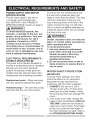
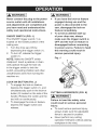
Polarized plugs - This saw has a plug
that looks like the one shown below:
To reduce the risk of electrical shock,
this saw has a polarized plug (one
blade is wider than the other). This plug
will fit in a polarized outlet only one
way. If the plug does not fit fully in the
outlet, reverse the plug. If it still does
not fit, contact a qualified electrician to
install the proper outlet. Do not change
the plug in any way.
IA,WARNING
I
Double insulation does not take the
place of normal safety precautions
when operating this tool.
To avoid electrocution:
1. Use only identical replacement
parts when servicing a tool with
double insulation. Servicing
should be performed by a
qualified technician.
2. Do not use power tools in wet or
damp locations or expose them to
rain or snow.
MOTOR
SAFETY
PROTECTION
IMPORTANT:
To avoid motor damage, the motor
should be blown out or vacuumed
frequently to keep sawdust from
interfering with the motor ventilation.
1. CONNECT this saw to a 120 V,
15 Amp circuit with a 15 Amp timedelay fuse or circuit breaker. Using
the wrong size fuse can damage the
motor.
2. If the motor won't start, release the
trigger switch immediately. UNPLUG
THE SAW. Check the saw blade to
make sure it turns freely. If the blade
is free, try to start the saw again. If
the motor still does not start, refer to
the TROUBLESHOOTING GUIDE.
3. If the tool suddenly stalls while
cutting wood, release the trigger
switch, unplug the tool, and free the
blade from the wood. The saw may
now be started and the cut finished.
4. FUSES may "blow" or circuit
breakers may trip frequently if:
a. MOTOR is overloaded overloading can occur if you feed
too rapidly or make too many
start/stops in a short time.
b. LINE VOLTAGE is more than
10% above or below the
nameplate voltage rating. For
heavy loads, the voltage at
motor terminals must equal the
voltage specified on the nameplate.
c. IMPROPER or dull saw blades
are used.
5. Most motor troubles may be traced
to loose or incorrect connections,
overload, low voltage or inadequate
power supply wiring. Always check
the connections, the load and supply
circuit if the motor doesn't run well.
Check minimum gauge for the length
of cord you are using on the chart
below.
GUIDELINES
FOR EXTENSION
CORDS
Use a proper extension cord. Make
sure your extension cord is in good
condition. When using an extension
cord, be sure to use one heavy enough
to carry the current your product will
draw. An undersized cord will cause a
drop in line voltage, resulting in loss
of power and cause overheating. The
table below shows the correct size
to use depending on cord length and
nameplate ampere rating. If in doubt,
use the next heavier gauge. The
smaller the gauge number, the heavier
the cord.
Be sure your extension cord is
properly wired and in good condition.
Always replace a damaged extension
cord or have it repaired by a qualified
person before using it. Protect your
extension cords from sharp objects,
excessive heat and damp or wet areas.
Use a separate electrical circuit for
your tools. This circuit must not be
less than a #12 wire with a 20 Amp
time-lag fuse or a #14 wire with a
15 Amp time-lag fuse. NOTE: When
using an extension cord on a circuit
with a # 14 wire, the extension cord
must not exceed 25 feet in length.
Before connecting the tool to the power
line, make sure the switch is in the
OFF position and the electric current is
rated the same as the current stamped
on the motor nameplate; running at a
lower voltage will damage the motor.
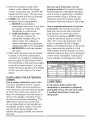
Q=
•
O=m
(When usng 120 volts only)
Ampere Rating
MoreThan
Not MoreThan
Total length of Cord
25ft. 50ft. 100ft. 150ft,
0
6
6
10
18
18
16
16
16
14
14
12
10
12
16
16
14
12
i CAUTION
i
in all cases make certain the
receptacle in question is properly
grounded. If you are not sure, have
a certified electrician check the
receptacle.
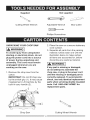
Supplied
Not supplied
Cutting Wheel Wrench
Adjustable Wrench
Box Cutter
Phillips Screwdriver
UNPACKING YOUR CHOP SAW
2. Place the saw on a secure stationary
work surface.
WARNING
1
3. Separate all parts from the packing
material. Check each one with the
illustration below to make certain
all items are accounted for, before
discarding any packing material.
To avoid injury from unexpected
starting or electrical shock, do not
plug the power cord into a source
of power during unpacking and
assembly. This cord must remain
unplugged whenever you are
working on the saw.
WARNING]
If any part is missing or damaged,
do not attempt to assemble the
chop saw, or plug in the power cord
until the missing or damaged part is
correctly replaced. To avoid electric
shock, use only identical replacement
parts when servicing double insulated
tools. Call 1-8004-MY-HOME ®for
replacement parts.
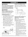
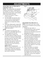
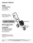
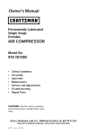
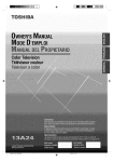
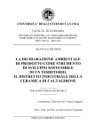
1. Remove the chop saw from the
carton.
iMPORTANT: Do not lift chop saw
by the switch grip (1). It may cause
misalignment. Lift machine by the
built-in carry handle (2).
2
1
Chop Saw
Cutting Wheel Wrench
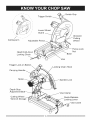
14
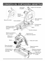
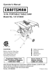
Switch Grip
Trigger Switch
Lower Wheel
Guard
Abrasive
Cutting Arm
Cutting
Wheel
Adjustable
Fence Lock
Nut
Head Hold-down
Locking Chain
Base
Vise
Trigger Lock-on Button
.Locking Chain Hook
Carrying Handle.....
Spindle Lock
Depth Stop
Adjustment
J
Cutting Wheel
Wrench Storage
Vise Clamp
Quick-Release
Locking Lever
Vise Crank
i,_
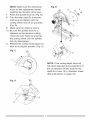
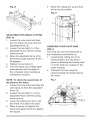
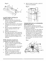
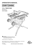
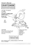
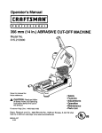
STORING THE WRENCH (FIG. B)
When you are not using the cutting
wheel wrench (1) provided, a storage
holder (2) is located on the rear of the
saw base.
VVARNING i
Never connect the plug to the power
source outlet until all installations
and adjustments are completed and
you have read and understood the
safety and operational instructions.
Fig. B
Ira,WAR.I.G
1
Failure to unplug your saw could
result in accidental starting causing
possible serious personal injury.
RAiSiNG AND LOCKING THE
CUTTING HEAD (FIG. A)
1. For shipping purposes, the cutting
head is locked in the down position.
2. Push down on the upper arm
assembly and remove the locking
chain (1) from the hook (2).
NOTE: This chain is held in place
by a tie down cord for shipping
purposes. Carefully cut this cord
with a box cutter or scissors.
3.
2
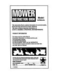
iNSTALLiNG AND CHANGING THE
ABRASIVE CUTTING WHEEL
(FIG. C, D, E)
NOTE: Use only recommended
reinforced abrasive wheels (rated
3,600 RPM or greater).
1. Raise the cutting handle to the
upward position.
2. Raise the cutting wheel guard (1)
to the uppermost position. (Fig. C)
3. Place the cutting wheel wrench (2)
on the arbor bolt (3). (Fig. D)
4. Push and hold in place the spindle
lock (4) and then loosen the arbor
bolt (3) counterclockwise with the
cutting wheel wrench (2) provided.
(Fig. D, E)
5. Remove arbor bolt (3), outer wheel
flange (6) and the abrasive cutting
wheel (5). (Fig. E)
6. Install the new abrasive cutting
wheel followed by the outer wheel
flange (6) and then the arbor bolt
(3), (Fig, E)
After releasing the locking chain (1),
move the cutting head to the
upward position. Do not remove the
chain, as you will need it for locking
the arm down for storage,
Fig. A
1
2
1
16
NOTE: Make sure the directional
arrow on the replacement wheel
matches the direction of the saw.
7.
8.
9.
Fig. E
3
Press the spindle lock (4). (Fig. E)
Turn the arbor bolt (3) clockwise
until snug and tighten with the
cutting wheel wrench (2) provided.
(Fig. D)
Make sure the wheel is secure.
10. Be sure the spindle lock (4)is
released so the abrasive cutting
wheel (5) turns freely by spinning
the cutting wheel until the spindle
lock (4) disengages.
11. Release the cutting wheel guard (1)
back to its original position. (Fig. C)
Fig. C
1
\
\
\
Fig. D
NOTE: If the cutting depth stop bolt
has been adjusted during operation of
the old abrasive wheel, reset for the
depth for a new 14 in. diameter wheel.
(See instructions on page 18)
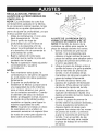
ADJUSTING
THE
CUTTING DEPTH
STOP BOLT (FIG.F)
NOTE: The cutting
depth was adjusted
properly at the factory. If adjustments
are needed, be careful not to adjust the
depth stop bolt too deep, as the cutting
wheel may contact the base.
1. Loosen the Iocknut (1) with a
13 mm wrench.
2.
3.
to decrease the cutting depth or
clockwise to increase the cutting
depth.
Lower the cutting head to check that
the wheel does not contact the base.
Repeat until adjusted properly and
tighten the Iocknut.
NOTE:
o
2
Turn the depth stop bolt (2) with a
13 mm wrench counterclockwise
4.
o
Fig. F
To maintain this adjustment, the
Iocknut (1) on the depth stop bolt (2)
must be tightened securely.
The depth stop is factory set
providing maximum cutting capacity
for the 14 in. abrasive cutting wheel
provided with your chop saw. When
the diameter of the wheel has
reduced in size due to normal wear,
the depth stop bolt may require
adjustment to provide maximum
cutting capacity.
NOTE: When a replacement
wheel is installed onto the unit, it is
necessary to check the clearance
of the cutting wheel to the machine
base before operating.
ADJUSTING THE VISE (FIG. G)
NOTE: The vise of your saw is used
to secure the workpiece during cutting
operations.
1. Rotate the vise crank (1)
counterclockwise to allow enough
room for the workpiece to fit
between the vise clamp (2) and the
adjustable fence (3).
2. Position the workpiece between the
vise clamp and the adjustable fence.
Turn the vise crank (1) clockwise to
clamp the workpiece securely.
3. The vise incorporates a quick
release locking lever (4). To use the
quick release feature, lift up on the
quick release locking lever (4) and
slide the vise clamp in or out to the
desired position.
4. When vise clamp is in desired
location, flip the quick release
locking lever (4) down to engage
the threads with the threads of the
vise. Begin to turn the vise crank (1)
clockwise to secure the workpiece
within the vise.
Fig.G
.
Raise the cutting arm up and lock
the fence into position.
Fig. H
4
1
2
4
ADJUSTING
FORANGLE
CUTTING
3
(FIG. H)
1. Loosen the vise crank and back
the vise clamp (3) away from the
2.
adjustable fence (2).
Loosen the two bolts (1) of the
adjustable fence with the cutting
wheel wrench.
3.
Move the adjustable fence (2) to
the desired angle between 0 and
45 degrees.
4.
5.
Tighten the two bolts (1).
The vise clamp (3) will align itself
automatically with the angle of
the workpiece when clamping a
workpiece in position,
NOTE: To check the squareness of
the blade to the fence:
1. Loosen the vise crank and back the
2.
vise clamp (3) from the adjustable
fence (2).
Loosen the two bolts (1) on the
adjustable fence with the cutting
wheel wrench.
3.
4.
Lower the cutting arm down until
the wheel (4) is below the base.
Place a square (5) against the
wheel and adjust the fence against
the square,
CARRYING YOUR CHOP SAW
(FIG. I)
The chop saw can be transported to
any workplace conveniently by:
1. Lowering the cutting arm to its
lowest position and securing in
place by attaching the locking chain
(1) to the hook (2), located on the
motor housing.
2. Transport the saw using the
carrying handle (3)located above
the motor.
Fig. I
2
1
i
[_
Never connect the plug to the power
source outlet until all installations
o
I_
WARNING
and adjustments are completed and
you have read and understood the
safety and operational instructions.
o
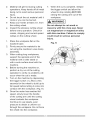
ON/OFF SWITCH (FIG. J)
The ON/OFF trigger switch (1) is
located on the handle position of the
cutting arm.
1. Turn the chop saw ON by
depressing the trigger switch (1).
2. To turn off, release the trigger
switch (1).
NOTE: Make the ON/OFF switch
2.
tool will run continuously.
To disengage the lock-on feature,
depress the trigger switch and
release.
If you have the lock-on feature
engaged during use and the
power is disconnected
to the
saw, disengage the lock-on
feature immediately.
To avoid accidental start-up
of your chop saw, always
make sure the trigger switch is
OFF and the lock-on feature is
disengaged before connecting
to power source. Failure to heed
this warning could result in
serious personal injury.
Fig. J
3
childproof. Insert a padlock or chain
with padlock through the hole (3)
in the trigger switch to lock the
switch, preventing children and other
unauthorized users from turning the
machine on.
LOCK-ON BUTTON (FIG. J)
1. To engage the lock-on feature,
depress the trigger switch (1), and
simultaneously push in the lock-on
button (2) located on the side of the
handle. Release the switch and the
WARNING]
2
CUTTING A WORKPIECE
l_,
WARNING
(FIG. K)
1
Failure to heed the safety rules
could result in serious personal
injury:
o To avoid serious personal injury,
always make sure the adjustable
fence is secured in position.
o Never perform any cutting
operation freehand (without placing
workpiece in the vise).
o Materialwillgethotduringcutting 7. Whenthecutis complete,
release
operations.
Keephandsoffof metal
thetriggerswitchandallowthe
beingcuttoavoidseriouspersonal
wheeltostoprotatingBEFORE
injury.
raisingthecuttingarmoutof the
o Donottouchthecutmaterialuntilit
workpiece.
coolsor youcanbeburned.
WARNING
J
o Keepyourhandsatleast3 in.from
thecuttingwheel.
Do not attempt to cut wood or
o Inspecttheabrasivecuttingwheel masonry with this chop saw. Never
beforeeveryoperation.Checkfor
cut magnesium or magnesium alloy
cracks,chippingandcorrectspeed with this machine. Failure to comply
ratingsonthecuttingwheel.
could result in serious personal
injury.
1. Placetheworkpiece
flatonthe
machinebase.
2. Firmlysecurethematerialtobe
cutusingthemachine's
viseclamp
assembly.
3. Whencuttinglongworkpieces,
supporttheoppositeendofthe
materialwitha rollerstandor
witha worksurfacelevelwiththe
machine.
4. Beforeturningthemachineon,
performa dryrunofthecutting
operationtoverifynoproblems
will
occurwhenthecutis made.
5. Turnonthemachineby depressing
thetriggerswitch(1).Allowafew
secondsforthewheelto buildupto
fullspeedbeforelettingitcomeinto
contactwiththeworkpiece.
(Fig.K)
6. Oncethemotorhasreachedfull
speed,slowlylowerthehandle
ofthecuttingarmuntilthecutting
wheelcontactstheworkpiece.
Continueto usesteady,even
pressuretoobtaina uniformcut
throughtheworkpiece.
Donotforce
thewheelintotheworkpiece.
Fig. K
i_
WARNING
,
i
Never put lubricants on the abrasive
wheel while it is spinning. To avoid
fire or toxic reaction, never use
gasoline, naphtha acetone, lacquer
thinner or similar highly volatile
solvents to clean the chop saw.
To avoid injury from unexpected
starting or electrical shock, unplug
the power cord before working on
the tool. To avoid electrical shock,
fire or injury, use only parts identical
to those identified in the parts list.
Reassemble exactly as the original
assembly to avoid electrical shock.
Pull out the brush assembly (3) and
replace with the new one, if needed.
The ears on the metal end of the
assembly go in the same slots the
carbon part fits into. Tighten the
cap snugly, but do not overtighten.
Repeat for the other side.
NOTE: To reinstall the same brushes,
first make sure the brushes go back in
the way they came out. This will avoid
a break-in period that reduces motor
performance and increases wear.
Fig. L
/1
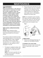
REPLACING CARBON BRUSHES
(FIG. L)
NOTE: Before replacing carbon
brushes, make sure the machine has
been disconnected from the power
source.
2
The carbon brushes furnished will last
approximately 50 hours of running time,
or 10,000 ON/OFF cycles. Replace
both carbon brushes when either
LUBRICATION
o
Motor and cutterhead bearings are
sealed and need NO lubrication.
has less than 1/4 in. length of carbon
remaining, or if the spring or wire is
damaged or burned.
,
To inspect or replace brushes, first
unplug the tool. Remove the black
plastic cap (1) on the side of the
motor (2).
NOTE: The brush assembly (3) has
a spring, so the cap (1) may pop
out when loosened.
CLEANING THE CHOP SAW
Keep your chop saw clean. Continually
remove metal chips, dust, dirt and
debris.
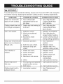
WARNING
l
To avoid injury from accidental starting, always turn the switch OFF and unplug the
tool before moving, replacing the abrasive cutting wheel or making adjustments.
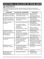
SYMPTOM
Chop saw wheel hits
base or work surface,
POSSIBLE CAUSES
1. The cutting depth
adjustment bolt is set
too deep.
CORRECTIVE ACTION
1. See "Adjusting the
Cutting Depth Stop
Bolt" section.
Cutting wheel does not 1. Depth stop bolt setting is 1. See "Adjusting the
cut through workpiece,
Cut is not square.
incorrect.
1. Defective wheel.
2. Work not positioned
properly.
3. Excessive wheel
pressure.
Chop saw wheel binds, 1. Improper operation.
ams, burns workpiece.
Rough cuts.
2. Dull chop saw wheel.
3. Improper chop saw
wheel.
Tool vibrates or
shakes.
1. Wheel not round.
2. Wheel damaged.
3. Wheel loose.
4. Machine is not secure.
5. Other.
Power head won't
fully rise.
Cutting head hard to
pull/push down.
1. Pivot spring not replaced
properly after service.
2. Part failure.
1. Lubrication needed.
Cutting Depth Stop
Bolt" section.
1. Replace immediately.
2. See "Adjusting for
Angle Cutting" section.
3. Lessen wheel pressure
during cutting operation.
1. See "Operation"
section.
2. Replace wheel.
3. Replace with 14 in.
abrasive cutting wheel.
1.
2.
3.
4.
Replace wheel.
Replace wheel.
Tighten arbor bolt.
Mount tool to
worksurface.
5. Call customer service.
1. Call customer service.
2. Call customer service.
1. See "Maintenance"
section.
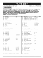
14 IN. ABRASIVE
CHOP SAW
MODEL NO. 137.375630
WARNING
i
When servicing use only CRAFTSMAN replacement parts. Use of any other
parts many create a HAZARD or cause product damage. Any attempt to
repair or replace electrical parts on this Chop saw may create a HAZARD
unless repair is done by a qualified service technician. Repair service is
available at your nearest Sears Service Center.
PARTS LiST FOR CHOP SAW
I.D.
Description
Size
I.D.
Description
Size
1
0KSR
CR. RE. COUNT HD. SCREW
M6_1.0-30
4
OF5V SUPPORT
1
0K9E
CR. RE, TRUSS HD. TAPPING
SCREW
M4_16-12
2
OF5X CLUTCH
1
0K9L
CR. RE, TRUSS HD. TAPPING
SCREW
M4_16-10
2
1
0KDN
CR. RE, PAN HD. SCREW
M5_0.8-25
8
1
0KMR
HEX. NUT
M5_0.8 T=4
9
1
0KMY
HEX. NUT
M8_1.25 T=6.5
1
4
0KQX
NUT
M6_1.0 T=6
3
OF7C FLANGE
2
0KR3
LOCK NUT
OF7D COLLAR
2
0QQ1
CORD
1
0UHV
MOTOR
HANDLE (LEFT)
1
0UHW
MOTOR
HANDLE (RIGHT)
OF9Q NYLON WASHER
2
0WRG
DEPTH STOP ADJUSTMENT
OF9R SPECIAL BOLT
2
0YZW
CUTTING WHEEL LABLE
OFA1 CORD CLAMP
1
271T
FLAT WASHER
@8_15-1
OFA4 RUBBER PLUG
2
2ECV
ADJUSTABLE FENCE
6#
OF5S ViSE CLAMP
OF60
PLUNGER HOUSING
0F67
LOCKING
6#
6#
CHAIN
OF6A CUTTING WHEEL WRENCH
OF6B FOOT
6#
OF7G ABRASIVE CUTTING WHEEL
OF7L
HEX. HD. SCREW AND WASHER
M10_1.5
Q'ty
M6_1.0 T=6
GUARD
0J72
FLAT WASHER
1/4_5/8-1/16
1
2ED3
WRENCH STORAGE
OJ7K
FLAT WASHER
3/8_29/32-5/64
2
2EGC
CLEAR PANEL
0J93
SPRING WASHER
@10
2
2EYQ
SLIDER
OJ9T
SPRING WASHER
@5/16
1
2ZNC
LOWER WHEEL GUARD
WW-8
2
2ZNE
CENTER SHAFT
OJCV SPRING PiN
1
2ZPC
STEELCOVER
OJE7
C-RING
1
32UV
PLATE
OJEE C-RING
1
33YX
TORSION SPRING
C-RING
1
38VB
ON/OFF
OJEH C-RING
2
3BRA
OPERATOR'S
OJBO WAVE WASHER
OJEF
Q'ty
6#
6#
BOLT
M8_1.25-100
HOLDER
23#
ASSEMBLY
CQ
CQ
6#
TRIGGER SWITCH
23#
MANUAL
OJPC HEX. HD. BOLT
M6_1.0-12
1
3BSZ
LABEL
OJPE HEX. HD. BOLT
M6_1.0-20
1
3BTO
TRADEMARK
OJQ4 HEX. HD. BOLT
M10_1.5-25
2
3BT1
WARNING
OJQ7 HEX. HD. BOLT
M8_1.25-25
2
3C4N
BASE
OJUK HEX. SOC. HD. CAP BOLT
M6_1.0-16
2
3C9B
MOTOR ASSEMBLY
0K35
CR. RE. PAN HD. SCREW & WASHER
M5_0.8-25
1
3CAM
ViSE ASSEMBLY
OK3W CR. RE. PAN HD. SCREW & WASHER
M6_1.0-16
4
3CK1
POWER CABLE
LABEL
LABEL
6#
2
Z
W
<
<"
m
o
I
0
I
I
I
0J93 2
Ix5
_YX
I
32UV
/
0
m
z
0
O_
0
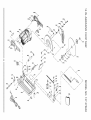
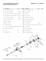
14 iN. ABRASIVE CHOP SAW
PARTS LiST FOR MOTOR
I.D.
Description
0F?Y
LOCKING
Size
OJX3
HEX. SOC.
0K37
CR. RE. PANHD.
0KAA
CR. RE. PAN HD. TAPPING
0KD7
CR. RE. PANHD.
0KDR CR. RE. PANHD.
HOOK
Q'ty
I.D.
Size
Description
1
2ZPN MOTOR
M5'0.8-8
2
2ZPP FLOW
& WASHER
M5'0.8-16
1
2ZPR CLEVIS
SCREW
M5'12-16
2
2ZPS PLATE COVER
SCREW
M4'0.7-10
2
2ZQ9 ARBOR
SCREW
M5'0.8-10
1
2ZS3 BRUSH HOLDER
0QQT BRUSH ASSEMBLY
2
3OFV INSULATING
0OR0 BRUSH COVER
2
3OXP FLAT WASHER
0R1S
BEARING
1
32F8 CR. RE. PANHD.
2LV6
CR. RE. PAN HEAD TAPPING& WASHERSCREW M5* 12-85
2
345J
2ZP1
COMPRESSION
2ZPL
ARM
2ZPM MOTOR
CHAIN
MODEL NO. 137.375630
SETSCREW
SCREW
BUSHING
COVER
SPRING
CABLE
REAR COVER
Q'ty
6#
GUIDE
PIN
SHAFT ASSEMBLY
ASSEMBLY
2
SLEEVE
SCREW
1
& WASHER
@6'13-1
1
M5"0.8-45
4
SHIELD
3C4S ARMATURE
ASSEMBLY
CQ
3C4T FIELD ASSEMBLY
6#
3C71 LEAD WiRE ASSEMBLY
30FV
3C4T
2ZPP
}aO_
_
OQROz
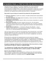
Congratu/ations on making a smart purchase. Your new Craftsman ® product
is designed and manufactured for years of dependable operation. But like all
products, it may require repair from time to time. That's when having a Repair
Protection Agreement can save you money and aggravation.
Here's what the Repair Protection
[]
[]
[]
[]
[]
Agreement*
includes:
Expert service by our 10,000 professional repair specialists
Unlimited service and no charge for parts and labor on all covered repairs
Product replacement up to $1500 if your covered product can't be fixed
Discount of 25% from regular price of service and related installed parts
not covered by the agreement; also, 25% off regular price of preventive
maintenance check
Fast help by phone - we call it Rapid Resolution - phone support from a
Sears representative. Think of us as a "talking owner's manual."
Once you purchase the Repair Protection Agreement, a simple phone call is all
that it takes for you to schedule service. You can call anytime day or night, or
schedule a service appointment online.
The Repair Protection Agreement is a risk-free purchase. If you cancel for any
reason during the product warranty period, we will provide a full refund. Or, a
prorated refund anytime after the product warranty period expires. Purchase
your Repair Protection Agreement today!
Some limitations and exclusions apply. For prices and additional
information in the U.S.A. call 1-800-827-6655.
*Coverage in Canada varies on some items. For full details call Sears
Canada at 1-800-361-6665.
Sears installation Service
For Sears professional installation of home appliances, garage door openers,
water heaters, and other major home items, in the U.S.A. or Canada call
1-800-4-MY-HOME ®.
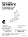
Manual del operador
®
SIERRA ABRASIVA PARA
CORTAR 14 PULGADAS
Modelo N.° 137.375630
C
US
PRECAUCION:
Antes de utilizar esta cortadora
sensitiva, lea este manual y siga
todas las reglas de seguridad y las
instrucciones de operaci6n.
Linea
de asistencia
a ciiente
1-800-843-1682
O
O
O
O
Instrucciones de seguridad
Instalaci6n
Funcionamiento
Mantenimiento
Centro
Sears de piezas
y reparaciones
1-800-488-1222
Sears Brands Management
Corporation
Hoffman
Estates,
IL 60179 USA
Yea la linea completa de productos Craftsman ® en craftsman.com
iPulse en el enlace Craftsman Club® y unase hoy mismo!
Pieza N. ° 137.375630001
Impreso en China
SECClON
Garantia ..................................................................................................
Especificaciones del producto .................................................................
Simbolos .................................................................................................
Seguridad en el manejo de herramientas el6ctricas ................................
Seguridad en el manejo de la cortadora sensitiva ...................................
Requisitos el6ctricos y seguridad ............................................................
Herramientas necesarias para el ensamble ............................................
Contenido de la caja ................................................................................
Conozca su cortadora sensitiva ...............................................................
Ensamble ................................................................................................
Ajustes ....................................................................................................
Funcionamiento .......................................................................................
Mantenimiento .........................................................................................
Guia para la solucidn de problemas ........................................................
Acuerdos para la protecci6n de reparaciones ..........................................
CRAFTSMAN
GARANTIA
COMPLETA
PAGINA
30
31
32
33
35
40
42
42
43
44
46
48
50
51
52
DE UN ANO
POR UN ArqO desde la fecha compra. Este producto es garantizado contra
defectos sobre material o mano de obra. El producto defectuoso
recibir_ reparaci6n gratuida o sustituci6n si la reparci6n no est_ disponible.
En cuanto a los detalles de esfera de garanfia sobre reparaci6n gratuida o
sustituci6n, s_rvase visitar el sitio web: www.craftsman.com
La presente garanfia no incluye la hoja, que es una parte consumible
y desgasta bano uso normal dentro el plazo de garantia. Esta garantia
es inv_lida si este producto es usado por causa de proveer los servicios
comerciales or alquilarse a otra persona. Esta garanfia le da derechos legales
especificos; usted podda tener otros derechos que vadan de un estado a otto.
Sears Brands Management Corporation, Hoffman Estates, IL 60179
A{_ ADVERTENCIA]
AIgunos polvos producidos
por lijar, aserrar, racier, taladrar y otras
actividades de construcci6n
contienen productos quimicos conocidos en el
Estato de California para causar carcinoma, defectos de nacimiento o otros
da_]os reproductivos.
AIgunos ejemplos de estos productos quimicos son:
o Pinturas a base de plomo.
o Silice de cristalino desde ladrillo, cemento y otros productos de mamposteria.
o Ars_nico y cromo de las maderas tratadas con productos quimicos.
El riesgo que implican estas exposiciones
varia seg_n la frecuencia con que
se realice este tipo de trabajo. Para reducir la exposici6n a estos productos
quimicos: trabaje en un _rea bien ventilada y utilice un equipo de seguridad
aprobado, tales como: mascaras de polvo que son dise_ados a fin de filtrar
las particulas microsc6picos.
_:_30
2012/12
MOTOR
Tipo .......................................................................................
Universal
Amperios ...............................................................................
Caballo de fuerza m_ximo ....................................................
15
3.5
Voltaje ...................................................................................
Hz .........................................................................................
120
60
R. P. M. (sin carga) ...............................................................
TamaSo de _rbol de rueda de cortar ....................................
3600
2,54 cm
TamaSo de rueda de cortar ...................................................
35,5 cm
CAPAClDAD
DE CORTE
Corte cruzado 0°
Redondo ............................................................................
Cuadrado ...........................................................................
12,7 cm
12 cm x 12 cm
Rectangular ........................................................................
7,5 cm x 21,1 cm
10,7 cm x 15,5 cm
11,5 cm x 13 cm
Corte a inglete 45 °
I_
Redondo ............................................................................
10,2 cm
Cuadrado ...........................................................................
10,2 cm x 10,2 cm
Rectangular ........................................................................
8,5 cm x 12,7 cm
Angulo de la prensa de tornillo de .......................................
0 ° ~ 45 o
ADVERTENCIA1
Para evitar riesgos de descargas el_ctricas, incendios o da_]os en las
herramientas, utilice una protecci6n para circuitos adecuada. Esta
herramienta est_ fabricada para funcionar con un voltaje de 110 V a 120 V.
Debe estar conectada a un fusible de retardo o a un interruptor de
circuitos de 110 V o 120 V y de 15 Amp. Para evitar descargas el_ctricas o
incendios, reemplace el cable el_ctrico inmediatamente si esta desgastado,
cortado o da_]ado de alguna manera. Antes de utilizar la herramienta, es
imprescindible que lea y entienda estas reglas de seguridad. Si no sigue
estas reglas, puede sufrir lesiones graves o dal]ar la herramienta.
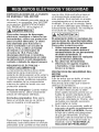
ICONOS DE ADVERTENCIA
La herramienta el_ctrica y el manual del usuario pueden contener "ICONOS
DE ADVERTENClAS" (simbolos dibujados para alertar o instruir al usuario
para que evite situaciones de riesgo). La comprensi6n y la observaci6n de
estos simbolos Io ayudaran a manipular su herramienta mejor y con m_s
seguridad. Abajo se muestran algunos de los simbolos que puede encontrar.
ALERTA DE SEGURIDAD:
Precauciones para su seguridad.
PROHIBIDO
UTILICE PROTECCION PARA LOS OJOS: Siempre use gafas o
anteojos de seguridad con protectores laterales.
UTILICE PROTECCION
RESPIRATORIA
utilice protecci6n respiratoria y auditiva.
Y AUDITIVA:
Siempre
LEA Y ENTIENDA EL MANUAL DE INSTRUCCIONES: Para reducir
el riesgo de lesiones, el usuario y todos los espectadores deben leer y
comprender el manual de instrucci6n antes de usar este producto.
MANTENGA LAS MANOS ALEJADAS DE LA HOJA: El no
mantener las manos alejadas de la hoja puede causar graves lesiones
personales.
APOYE LA PIEZA DE TRABAJO
ABRAZADERAS
f,&
{_
PELIGRO
Y ASEGURELA
CON
1 PELIGRO: Indica una situaci6n de riesgo inminente que, si
!
no se evita, puede ocasionar lesiones graves o la muerte.
ADVERTENCIA
{_{_ PRECAUCION
i ADVERTENClA:
Indica una posible situaci6n de
riesgo que, si no se evita, puede ocasionar lesiones
graves o la muerte.
i
PRECAUCION: Indica una posible situaci6n de
riesgo, que si no se evita, puede ocasionar lesiones
minimas o moderadas.
INSTRUCCIONES GENERALES DE
SEGURIDAD ANTES DE UTILiZAR
ESTA HERRAMIENTA ELECTRICA
La seguridad es una combinaci6n
de sentido com0n, precauci6n y
conocimiento del manejo de la herr
mienta el6ctrica.
PRECAUCION
Para evitar errores que podrian
ocasionarle lesiones graves, no
enchufe la herramienta hasta haber
leido y entendido Io siguiente.
1. _
LEA y familiadcese
jL_,_
con todo el Manual del
_
operador. APRENDA
todo Io relacionado con
la utilizaci6n, las limitaciones y los
posibles riesgos de la herramienta.
2. MANTENGA LOS PROTECTORES
EN SU POSICION yen correcto
funcionamiento.
3. EXTRAIGA LAS LLAVES
DE AJUSTE Y LAS LLAVES
INGLESAS. Acost0mbrese a
revisar la herramienta y a ver que
se extraigan de ella las Ilaves de
ajuste antes de ENCENDERLA.
4. MANTENGA LIMPIA ELAREA DE
TRABAJO. Los bancos y las _reas
de trabajo desordenados provocan
accidentes.
5. NO LA USE EN UN AMBIENTE
PELIGROSO. No use las
herramientas el6ctricas en lugares
hOmedos, ni las exponga a la Iluvia
o a la nieve. Mantenga el _rea de
trabajo bien iluminada.
6. MANTENGAALEJADOS
A LOS
NII_OS. Todos los visitantes y los
transeOntes deben permanecer a
una distancia segura del _rea de
trabajo.
7. EVlTE QUE 8U8 HERRAMIENTAS
PUEDAN 8ER UTILIZADA8 POR
LOS NI_IO8, mediante candados o
interruptores maestros, o mediante la
extracci6n de las Ilaves de encendido.
8. NO FUERCE LA HERRAMIENTA.
De esta manera, realizar_ su
trabajo mejor, con m_s seguridad
y a la velocidad para la que est_
dise_ada la herramienta.
9. UTILICE LA HERRAMIENTA
ADECUADA. No intente hacer que
la herramienta o los acoplamientos
realicen trabajos para los cuales no
fueron dise_ados.
10. UTILICE UNA EXTENSION
ELECTRICA ADECUADA.
AsegQrese de que la extensi6n
el6ctrica est6 en buenas
condiciones. AI utilizar una
extensi6n el6ctrica, asegQrese de
que sea suficientemente gruesa
para proporcionar la corriente que la
herramienta necesita. La utilizaci6n
de una extensi6n de menor medida
ocasionar_ una caida en el voltaje
de la linea y una p6rdida de
flujo el6ctrico que recalentar_ la
herramienta. Si tiene dudas, utilice
el calibre mayor m_s pr6ximo.
Cuanto menor sea el calibre, mayor
deber_ ser el grosor del cable.
11. USE LA VESTIMENTA
APROPIADA. No utilice ropa
suelta, guantes, corbatas, anillos
ni brazaletes u otros tipos de
alhajas que puedan atascarse en
las piezas m6viles. Se recomienda
utilizar calzado antideslizante.
Utilice una protecci6n para cubrir y
contener el cabello largo.
PROTECCION PARA
LOS
OJOS.
Cualquier
12. 0
UTILICE
SIEMPRE
herramienta el6ctrica
podda despedir y hacer que se
introduzcan en sus ojos objetos
extra_os que poddan ocasionar un
da_o permanente. Utilice SIEMPRE
gafas de seguridad (no lentes
comunes) que cumplan con la
norma de seguridad Z87.1 de ANSI,
Los lentes comunes s61otienen
cristales resistentes a los golpes.
NO SON gafas de seguridad.
NOTA: Los lentes o las gafas que
no cumplan con la norma ANSI
Z87.1 poddan ocasionarle graves
13.
14.
15.
16.
17.
18.
19.
UTILICE
UNAMASCARA
FACIAL O UNA
MASCARILLA CONTRA
EL POLVO. El trabajo
realizado con sierras produce polvo.
REALICE UN TRABAJO
SEGURO. Si le resulta
pr_ctico, utilice prensas o
un tornillo de banco para
sujetar el material de
trabajo. Es m&s seguro que utilizar
una mano y libera las dos manos
para manejar la herramienta.
DESCONECTE LAS
HERRAMIENTAS DE LA FUENTE
DE ENERGIA antes de realizar el
mantenimiento y cuando cambie
accesorios, como hojas, brocas y
cortadores.
REDUZCA EL RIESGO DE QUE
SE PRODUZCA UN ARRANQUE
NO DESEADO. AsegL_rese de que
el interruptor est6 en la posici6n de
APAGADO antes de enchufar la
herramienta.
UTILICE LOSACCESORiOS
RECOMENDADO8.Consulteel Manual
del operador para hallar los accesorios
recomendados. La utitizaci6nde los
accesorios inapropiados
puede implicar
riesgos de lesiones para usted o para
otras personas.
NUNCA SE PARE ENCIMA
DE LA HERRAMIENTA. Dar
vuelta la herramienta o tocar
accidentalmente la hoja de corte
puede ocasionarle lesiones graves.
COMPRUEBE QUE NO HAYA
PIEZAS DANADAS. Antes de
seguir utilizando la herramienta,
debe revisar cuidadosamente los
protectores u otras piezas que
est6n dafiados para comprobar que
funcionar_n correctamente. Revise
la alineaci6n y el acoplamiento de
las piezas m6viles y compruebe que
no haya roturas en las piezas o en
el montaje y que no existan otras
condiciones que puedan afectar su
funcionamiento. Los protectores
u otras piezas que est6n dafiados
deben arreglarse o reemplazarse
debidamente.
20. NUNCA DEJE DESATENDIDA
UNA HERRAMIENTA. CORTE EL
SUMINISTRO ELECTRICO. No se
aleje de una herramienta hasta que
la hoja se detenga por completo y
la herramienta est6 desenchufada
de la fuente de energia.
21. NO FUERCE LA POSTURA.
Mantenga el equilibrio y el apoyo
correcto de los pies en todo
momento.
22. NUNCA alargue la mano o el brazo
a trav6s el recorrido de la hoja de
corte. Nunca ponga la mano o el
brazo a trav6s de recorrido de corte
de la hoja.
23. MANTENGA LAS
HERRAMIENTAS CON CUIDADO.
Mantenga las herramientas
afiladas y fimpielas para que su
funcionamiento sea mejor y m_s
seguro. Siga las instrucciones para
la lubricaci6n y el reemplazo de los
accesorios.
24. NO utilice herramientas el6ctricas
en presencia de Iiquidos o gases
infiamables.
25. NO opere la herramienta bajo
la infiuencia de drogas, alcohol
o medicamentos que pudieran
afectar su capacidad para utilizar la
herramienta correctamente.
26. ADVERTENClA: El polvo originado
pot ciertos materiales puede ser
dafiino para su salud. Maneje
siempre la sierra en lugares bien
ventilados y proporcione un m6todo
adecuado para la remoci6n de
polvo.
27.@
AUDITIVA para reducir
el
riesgo de
p6rdida de la
UTILICE
PROTECCI6N
audici6n ocasionada por
el ruido.
ANTES DE UTiLIZAR LA
CORTADORA 8ENSiTIVA, ES
IMPRESCINDIBLE QUE LEAY
ENTIENDA ESTAS REGLAS DE
SEGURIDAD.
{_
ADVERTENCIA
CUANDO INSTALE O MUEVA LA
CORTADORA SENSITIVA:
1. EVITE HACERLO EN AMBIENTES
PELIGROSOS:
o Utilice la cortadora sensitiva
en interiores, en un lugar seco,
protegido de la Iluvia y de la
humedad.
o Mantenga bien iluminada el
_rea de trabajo.
2. PARA EVITAR LESIONES POR
MOVIMIENTOS INESPERADOS
DE LA CORTADORA SENSITIVA:
o Ajuste la cortadora sensitiva
con pernos o prensas sobre una
superficie firme y nivelada en la
que haya espacio suficiente para
mover la pieza de trabajo hasta
cortarla por completo.
o Ubique la cortadora con las patas
niveladas y no se balancee.
o Ubique la sierra de modo que
los operadores y los transe0ntes
permanezcan a una distancia
segura de la cortadora y no
est6n en linea recta con la hoja
de la herramienta.
o Para evitar lesiones por
descargas el6ctricas, aseg0rese
de que sus dedos no toquen las
espigas met_licas del enchufe
cuando conecte o desconecte la
cortadora sensitiva.
o APAGUE y desconecte la
cortadora sensitiva antes de
transportarla a otto lugar. Para
evitar lesiones en la espalda, pida
ayuda para realizar el transporte.
o Fije la cortadora sensitiva al piso
si tiende a moverse cuando corte
piezas de trabajo largas y pesadas.
o NO SE PARE frente a la
cortadora sensitiva. No guarde
materiales sobre la herramienta
ni cerca de ella. Si se para
frente a la herramienta, puede
sufrir lesiones graves.
1
PARA EVITAR ERRORES QUE
PODRIAN OCASIONARLE LESIONES
GRAVES O PERMANENTES,
NO ENCHUFE LA CORTADORA
SENSITIVA HASTA COMPLETAR
LOS SIGUIENTES PASOS:
1. Aprenda a utilizar la funci6n del
interruptor de ENCENDIDO y
APAGADO, del mango de corte y
del protector del disco.
2. Revise y entienda todas las
instrucciones de seguridad y los
procedimientos de utilizaci6n
indicados en este Manual del
operador.
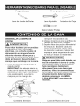
3. Revise los m6todos de mantenimiento
para esta cortadora sensitiva.
4. Encuentre y lea todas las etiquetas
de advertencia que se hallan en la
cortadora sensitiva:
o Lea el manual antes de utilizar la
cortadora sensitiva.
o Use gafas de seguridad.
o Nunca realice operaciones de
corte si no est_ colocado el
protector del disco.
o CORTE el suministro el6ctrico,
espere a que el disco abrasivo
se detenga y desconecte el cable
de alimentaci6n de la fuente de
energia antes de realizar los
ajustes o el mantenimiento.
5. El perno del _rbol y todas las
prensas deben ajustarse antes de
realizar cortes.
6. AsegOrese de que la pieza de
trabajo y el disco abrasivo no est6n
en contacto antes de utilizar la
cortadora sensitiva.
35
_,
ANTES DE CADA UTILIZACION
1. INSPECCIONE LA CORTADORA
SENSITIVA:
o Si alguna pieza falta, est_ doblada
o daSada de alguna manera, o si
alguna pieza el6ctrica no funciona
correctamente, APAGUE la
cortadora sensitiva y desench_fela.
o Reemplace las piezas que
falten o est6n daSadas antes de
utilizar la cortadora sensitiva.
2. PARA EViTAR LESIONES
POR OBSTRUCCIONES,
DESLIZAMIENTO80
PIEZA8
ARROJADA8 (CONTRAGOLPE8):
e Utilice esta cortadora sensitiva
Qnicamente para cortar
materiales ferrosos.
o Evite lesiones pot piezas que
puede arrojar la herramienta.
AsegOrese de que el disco
abrasivo est6 instalado
correctamente y de que el perno
del _rbol est6 ajustado.
o Utilice la herramienta adecuada.
No haga que la herramienta
realice trabajos para los cuales
no fue dise_ada.
3. INSPECCIONE EL AREA DE
TRABAJO:
o Mantenga limpia el _rea de
trabajo.
o Las _reas y los bancos de
trabajo desordenados provocan
accidentes. El piso no debe
estar resbaloso por la presencia
de cera o aserdn.
o Evite quemaduras u otros da_os
ocasionados por el fuego. No
utilice la cortadora sensitiva
cerca de Iiquidos, vapores o
gases inflamables.
o Antes de utilizar la cortadora
sensitiva, quite de la mesa
todos los objetos que no sean
necesarios para guiar la pieza
de trabajo hacia la cortadora.
o Evite lesiones. No realice el
trazado, el ensamble ni la
instalaci6n en la cortadora
sensitiva.
,
,
o Nunca sujete una pieza de
trabajo con las manos. La pieza
de trabajo se calentar_ mucho
al cortarla.
PLANIFIQUE EL TRABAJO:
o Antes de intentar realizar un
trabajo nuevo o poco comQn,
planifique cuidadosamente la
posici6n de las manos. AsegQrese
de contar con accesorios, topes
y otros articulos listos para usar.
Evite lesiones por la utilizaci6n de
recomendados. Utilice Qnicamente
los accesorios recomendados.
USE PRENDAS SEGURAS:
o Planifique c6mo se proteger_
los ojos, las manos, la cara y
los oidos.
o No use prendas sueltas,
guantes, corbatas ni alhajas
(anillos, relojes de pulsera).
Pueden atascarse y atraerlo
hacia las piezas mdviles.
o Use calzado antideslizante.
o Si tiene el cabello largo, _teselo.
o Arremangue hasta arriba del
codo las prendas con mangas
largas.
o Los niveles de ruido varian
ampliamente. Para evitar un
posible daSo auditivo, use
tapones o protectores para los
oidos cada vez que utilice la
cortadora sensitiva.
o La cortadora sensitiva puede
despedir y hacer que se
introduzcan en sus ojos objetos
extraSos que pueden ocasionar
un daSo permanente. Use
gafas de seguridad (no lentes
comunes) que cumplan con
las normas CSA. Los lentes
comunes sdlo tienen cristales
resistentes a los golpes. No son
gafas de seguridad.
o Use una mascarilla contra
el polvo junto con las gafas
de seguridad durante cada
operaci6n.
6. INSPECCIONE
LA
UN ERROR POR DESCUIDO.
RECUERDE QUE UN DESCUIDO DE
UNA FRACCION DE SEGUNDO ES
SUFIClENTE PARA OCASIONAR
UNA LESION GRAVE.
7.
1. MANTENGAA LOS NINOS
ALEJADOS:
o AsegOrese de que todos los
transeOntes est6n resguardados
de la herramienta el6ctrica
antes de y durante la utilizaci6n.
o Antes de utilizar la herramienta
el6ctrica, pruebe la sierra
encendi6ndola y dejando que
permanezca en movimiento
durante algunos segundos. Si
vibra o hace un ruido extra5o,
det6ngala inmediatamente.
APAGUE y desenchufe la
cortadora sensitiva. No vuelva
a encenderla hasta que el
problema se haya solucionado.
2. NO FUERCE LA HERRAMIENTA:
o Corte solamente una pieza pot
vez.
3. ANTES DE LIBERAR
MATERIALE8 ATASCADOS:
o Suelte el interruptor de gatillo.
o Espere a que todas las piezas
m6viles se detengan.
o Desenchufe la cortadora
sensitiva.
4. ANTES DE DEJAR LA
CORTADORA SENSITIVA:
o Suelte el interruptor de gatillo.
o Desenchufe la cortadora
sensitiva.
o Haga que el taller sea a
prueba de ni_os. Cierre con
Ilave el taller. Desconecte los
interruptores maestros,
8.
PIEZA DE
TRABAJO:
o AsegOrese de que no haya
clavos ni objetos extra5os en la
parte de la pieza de trabajo que
cortar_.
PLANIFIQUE EL CORTE:
o No realice cortes a pulso.
Guie la pieza de trabajo
firmemente contra la guia y
sobre la superficie de la mesa.
AsegOrese de que no haya
desechos entre la pieza de
trabajo y los soportes de 6sta.
o Extreme las precauciones con
piezas de trabajo muy grandes,
muy peque5as o de forma
irregular.
o Utilice soportes adicionales
(mesas, caballetes, bloques) si
resulta dificil sujetar la pieza de
trabajo en la mesa. No utilice
a otra persona como soporte
adicional ni para que Io ayude a
guiar, sujetar o empujar la pieza
de trabajo.
o No corte m_s de una pieza de
trabajo cada vez.
o No ENCIENDAla cortadora
sensitiva antes de despejar
todo Io que haya sobre la mesa,
excepto la pieza de trabajo
y los dispositivos de soporte
relacionados.
EVITE ENCENDIDOS
ACCiDENTALE8:
AsegQrese de que el interruptor
est6 en la posici6n de APAGADO
antes de enchufar la cortadora
sensitiva abrasiva a la fuente de
energia el6ctrica.
CUANDO LA CORTADORA
SENSITIVA ESTE FUNCIONANDO
PRECAUCION
®
{_
PRECAUCION
i
NO PERMITA QUE EL HECHO DE
ESTAR FAMILIARIZADO CON LA
CORTADORA SENSITIVA DEBIDO
A LA UTIMZACION FRECUENTE DE
LA MISMA LO LLEVE A COMETER
i
La medida maxirna de discos
abrasivos que puede utilizarse
en esta cortadora sensitiva es
un disco de 14" (35,5 cm). Nunca
utilice discos tan gruesos que
hagan que el reborde exterior se
enganche con las partes planas
e
o
o
o
del husillo. Los discos mas
grandes entraran en contacto
con los protectores para discos,
mientras que los mas gruesos
evitaran que el pemo los sujete
en el husillo. Cualquiera de estas
situaciones puede ocasionar
un accidente serio y tambien
ocasionarie graves lesiones
corporaies.
No intente cortar madera ni
materiales de albaSileria con
esta cortadora sensitiva. Nunca
corte magnesio ni aleaciones
de magnesio con esta m&quina.
Si no cumple con estas reglas,
corre el riesgo de sufrir lesiones
corporales graves.
Para evitar que la cortadora
sensitiva se mueva o se voltee
mientras usted realiza un
corte, suj_tela a en banco o en
una superficie de trabajo que
tambi_n est_ asegurada.
Utilice siempre el tornillo de
banco de la cortadora sensitiva
para evitar accidentes que
pueden ocasionarle graves
lesiones corporales.
Nunca se pare delante de la
cortadora ni deje que alguna
parte de su cuerpo quede en
linea con la trayectoria del disco.
Si Io hace, puede producirse un
accidente que puede ocasionarle
graves lesiones corporales.
{_
PRECAUCION
Los
materiales
1
grandes,
irregular
forma circular o
pueden necesitar
adicionales
asegurarlos
los
cortes.
de
Utilice
m_todos
sujeci6n
correctamente
prensas
de
para
durante
"C"
que puedan montarse en los lados
izquierdo y frontal de la base de la
maquina. Utilice tambi_n
topes
para
sujetar el material
firmemente.
Si no
cumple con estas reglas,
corre el
riesgo de sufrir lesiones
corporales
graves.
i_,
PRECAUCION
i
Para
evitar
accidentales
de
encendidos
la cortadora
sensitiva,
asegQrese
siempre de que el interruptor est_
en la posici6n de apagado y de
que la funci6n de "bloqueo" est_
desactivada antes de conectar la
cortadora a la fuente de energia
el_ctrica. Si no presta atenci6n a
esta advertencia, corre el riesgo de
sufrir lesiones corporales graves.
o UTIMCE UNICAMENTE LOS
DISCOS APROPIADOS. No utilice
discos con orificios de tamaSo
incorrecto. Nunca utilice arandeias
o tomilios para discos si est_n
defectuosos o son inapropiados. La
medida m_xima de discos abrasivos
que puede utilizarse en esta
cortadora sensitiva es un disco de
14" (35,5 cm).
o NO EXTRAIGA LOS
PROTECTORES DEL DISCO DE
LA SIERRA SENSmVA. Nunca
utilice la cortadora sensitiva si
falta extraer algL_nprotector o
alguna cubierta. AsegL_rese de que
todos los protectores funcionen
correctamente antes de cada
utilizaci6n.
o MANTENGA LAS MANOS
ALEJADAS DEL AREA DE
CORTE. Mantenga las manos
alejadas del disco. No coloque
las manos debajo dei material de
trabajo ni alrededor ni debajo del
disco mientras 6ste gira. No intente
quitar el material cortado mientras
el disco est6 girando.
o NUNCA UTILICE LA SIERRA EN
AMBiENTES EXPLOSIVOS. Las
chispas normales dei motor o las
generadas al cortar metales pueden
encender los gases.
o NO UTILICE LA HERRAMIENTA Sl
EL INTERRUPTOR NO FUNClONA
CORRECTAMENTE. Haga que
un centro de servicio autorizado
reemplace los interruptores
defectuosos,
o
o
o
o
o
o
o
o
o
o
o
MANTENGA LA HERRAMIENTA
SECA, LIMPIA Y LIBRE DE
ACEITES Y GRASAS, Utilice
siempre un paso limpio cuando
limpie la herramienta. Nunca utilice
Iiquido de frenos, gasolina, productos
a base de petr61eo u otros solventes
para limpiar la herramienta.
UTILICE SIEMPRE SOPORTES
PARA LAS PIEZAS DE TRABAJO
LARGAS. Para reducir al minimo el
riesgo de que se voltee la m_quina,
siempre sujete con soportes las
piezas de trabajo largas.
ANTES DE REALIZAR UN
CORTE, ASEGURESE DE QUE
TODOS LAS PIEZAS ESTEN
CORRECTAMENTE SUJETADAS.
UTILICE SIEMPRE EL TORNILLO
DE BANCO para asegurar la pieza
de trabajo.
NUNCATOQUE EL DISCO ni
ninguna otra pieza m6vil durante la
utilizaci6n.
NUNCA ENClENDALA
CORTADORA SENSITIVA
CUANDO EL DISCO ESTE EN
CONTACTO CON LA PIEZA DE
TRABAJO.
NUNCA corte m_s de una pieza de
trabajo a la vez.
NO COLOQUE m_s de una pieza
de trabajo a la vez sobre la base de
la m_quina a la vez.
NUNCA REALICE CORTES "A
PULSO". Asegure siempre la pieza
de trabajo en el tornillo de banco.
NUNCA sostenga una pieza de
trabajo con la mano. La pieza
de trabajo se calentar_ mucho al
cortarla.
NUNCA coloque las manos detr&s,
debajo o dentro de las 3" (7,5 cm) de
distancia del disco y de la trayectoria
de corte pot ninguna raz6n.
NUNCA trate de levantar una pieza
de trabajo, un trozo de material
desechable o cualquier otra cosa
que est6 cerca de la trayectoria de
corte del disco.
o ASEGURESE DE QUE EL DISCO
ESTE MONTADO FIRMEMENTE,
como se describe en las
instrucciones de utilizaci6n, antes
de conectar la herramienta a la
herramienta el6ctrica. No ajuste el
disco excesivamente, ya que esto
puede hacer que se quiebre.
o COMPRUEBE QUE NO EXISTAN
FISURAS NI RAJADURAS EN EL
DISCO que funcione correctamente
antes de su utilizaci6n.
o SlEMPREAPOYE
DESPAClO
EL DISCO ABRASlVO CONTRA
LA PIEZA DE TRABAJO cuando
comience a cortar. Un impacto
brusco puede romper el disco.
o UTILICE UNICAMENTE UN DISCO
PARA CORTADORA SENSITIVA
PREPARADO PARA FUNCIONAR
A 3600 R. P. M. O MAS y fabricado
segOn la norma ANSI B 7.1. Guarde
siempre los discos en un lugar
seco con variaciones leves de
temperatura.
• ANTES DE REALIZAR UN CORTE,
presione el interruptor de gatillo y
permita que el disco desarrolle la
m_xima velocidad.
o Esta cortadora sensitiva esta
diseSada para cortar metales,
utilizando _nicamente discos
para cortadoras sensitivas
abrasivas. No extraiga el disco,
no instale una hoja de acero
ni intente cortar otros tipos
de materiales, como madera,
materiales de albaSileria, etc.
Si intenta cortar estos tipos de
materiales, puede causar un
accidente que puede ocasionarle
graves lesiones corporales.
o No intente modificar esta
herramienta ni crear accesodos no
recomendados para set utilizados
con esta herramienta. Cualquier
alteraci6n o modificaci6n de este
tipo significa un real uso de la
herramienta y puede ponedo en
desgo de lesi6n grave.
ESPECIFICACIONES
DELA
FUENTE
DE ENERGIA Y DEL MOTOR
El motor CA utilizado para esta sierra es
universal y no reversible. Vea "MOTOR"
en la secci6n "ESPECIFICACIONES
DEL PRODUCTO" de la p_gina 31.
{_
ADVERTENCIA
i
Para evitar riesgos de descargas
el_ctricas, incendios o daSos en las
herramientas, utilice una protecci6n
para circuitos adecuada. La sierra
est_ diseSada para funcionar a
120 V. Con_ctela a un circuito de
120 Vy 15A, y utilice un fusible
de retardo o un interruptor de
circuitos de 15 A. Para evitar
descargas el_ctricas o incendios,
reemplace inmediatamente el cable
de alimentaci6n si est_ desgastado,
cortado o daSado de alguna manera.
REQUISiTOS ELI_CTRICOS =
DOBLE AISLAMIENTO []
La herramienta el6ctrica tiene doble
aislamiento para proporcionar un
aislante de doble espesor entre usted y
el sistema el6ctrico de la herramienta.
Todas las piezas met_licas expuestas
est_n aisladas de los componentes
internos de metal del motor con una
protecci6n aislante.
Piezas de reemplazo: Cuando realice
el mantenimiento, utilice Qnicamente
piezas de reemplazo id6nticas.
Enchufes polarizados: Esta sierra
tiene un enchufe que se ve como el
que se muestra a continuaci6n:
Para reducir el riesgo de descargas
el6ctricas, esta sierra tiene un enchufe
polarizado (una cuchilla es m_s ancha
que la otra). Este enchufe encaja en
un tomacorriente polarizado en un
solo sentido. Si el enchufe no encaja
completamente en el tomacorriente,
invi6rtalo. Si aun asi no encaja, flame
a un t6cnico calificado para instalar un
tomacorriente apropiado. No modifique
el enchufe de ninguna manera.
i_
ADVERTENCIA
i
El aislamiento doble no reemplaza las
precauciones de seguridad aplicables
para la utilizaci6n de esta herramienta.
Para evitar la electrocuci6n:
1. Utilice _nicamente las piezas
de reemplazo cuando realice el
mantenimiento de una herramienta
de doble aislamiento. El
rnantenimiento debe set realizado
por un tecnico ¢alificado.
2. No utilice las herramientas
el_ctricas en lugares mojados
o hemedos, ni las exponga a la
Iluvia o a la nieve.
PROTECCION DE SEGURIDAD DEL
MOTOR
IMPORTANTE:
A fin de evitar que se da_e, el motor
debe ser soplado o aspirado con
frecuencia para evitar que el aserdn
obstruya la ventilaci6n.
1. CONEOTE esta sierra a un circuito
de 120 V. Este circuito no debe
tenet cables menores al #12 con un
fusible de acci6n retardada de 20
Amp o un cable #14 con un fusible
de acci6n retardada de 15 Amp. Uso
de fusible con tama_o incorrecto
podr_ da_ar el motor.
2. Si el motor no se enciende, suelte el
interruptor de gatillo inmediatamente.
DESENCHUFE LA SIERRA. Revise
la hoja de la sierra para asegurarse
de que gire libremente. Si la hoja
est_ libre, trate de encender la sierra
nuevamente. Si aun asi el motor no
enciende, vea la "GUIA PARA LA
SOLUClON DE PROBLEMAS".
3. Si laherramienta
sedetiene
m_quina. La siguiente tabla muestra
repentinamente
mientras
corta
la medida correcta que debe utilizar
madera,
suelteelinterruptor
de
segOn el largo de la extensi6n y el
gatillo,desenchufe
laherramienta
y
tango de amperios especificado en la
liberelahojadelamadera.
Ahora,la
placa. Si tiene dudas,utilice el calibre
sierrapuedeencenderse
nuevamente,mayor m_s pr6ximo. Cuanto menor
y puedeterminarse
elcorte.
sea el calibre, mayor deber_ ser el
4. LOSFUSIBLES
pueden"estallar", grosor del cable.
o losinterruptores
decircuito
Aseg6rese de que la extensi6n
puedensaltarfrecuentemente
si:
el_ctrica est_ bien conectada yen
a. ELMOTORest_sobrecargado. buenas condiciones. Reemplace siempre
Lasobrecarga
puedeproducirse las extensiones el6ctricas daSadas
si ustedalimentala sierra
o haga que un t6cnico calificado las
demasiado
r_pidoo si enciende repare antes de utilizarlas. Proteja las
y apagala sierramuchasveces extensiones el6ctricas contra los objetos
enpocotiempo.
y el calor excesivo, y al6jelas de
b. ELVOLTAJEDE LA LINEA est_ afilados
las _reas hOmedas o mojadas.
m_s de un 10% encima o debajo
del rango de voltaje especificado
en la placa informativa. Para las
cargas pesadas, el voltaje de las
terminales del motor debe ser
igual al voltaje especificado en la
placa informativa.
c. SE UTILIZAN HOJAS PARA
SIERRA INAPROPIADAS o
desafiladas.
5. La mayoda de los problemas en
los motores puede atribuirse a
conexiones sueltas o incorrectas,
a sobrecargas, al bajo voltaje o a
cableados de fuente de energia
inadecuados. Revise siempre las
conexiones, la carga y el circuito
el6ctrico si el motor no funciona
correctamente. Revise, en el cuadro
de abajo, el calibre minimo para el
largo de extensi6n que utilizar_.
INDICACIONES PARA LAS
EXTENSIONES ELECTRICAS
Utilice una extensi6n el6ctrica
apropiada. Aseg0rese de que
la extensi6n el6ctrica est6 en
buenas condiciones. AI utilizar una
extensidn el6ctrica, aseg0rese de
que sea suficientemente gruesa
para proporcionar la corriente que la
herramienta necesita. Una extensi6n
el6ctrica de menor medida puede
ocasionar una caida en el voltaje de la
linea y, en consecuencia, una p@dida
de potencia y el recalentamiento de la
Use un circuito el_ctrico aparte para
sus herramientas.
Este circuito no
debe tenet cables menores al #12 con
un fusible de acci6n retardada de
20Amp o un cable #14 con un fusible
de acci6n retardada de 15 Amp.
NOTA: Cuando use un cable de
extensi6n en un circuito con un cable
#14, el cable de extensi6n no debe
ser mayor de 7,6 metros de Iongitud.
Antes de conectar el motor a la linea
de energia, aseg0rese de que el
interruptor est6 Apagado y que la
corriente el6ctrica sea la indicada en la
placa informativa del motor. Hacer
funcionar la herramienta a un voltaje
menor daSar_ el motor.
(S61o cuando
Rango de amperios
mas de
0
6
10
,_
no mas de
la corriente es de 120 V)
Largo
total de la extensi6n
25'
50'
6
18
10
12
18
16
PRECAUClON
(en pies)
100'
150'
16
16
14
16
16
14
14
12
12
]
En todos los casos, aseg_rese de que
el tomacorriente este correctamente
¢onectado a tierra. 8i no esta seguro,
haga que un tecnJ¢o calificado revise
el tomacorriente.
Proporcionada
Nose proporciona
LlavedeRuedadeCortar
LlaveAjustable Cortadora
deCaja
Destornillador
Phillips
DESEMBALAR LA SIERRA DE
CORTAR
[_
ADVERTENCIA
i
Para evitar lesiones pot encendidos
inesperados o por descargas
el_ctricas, no enchu{e el cable de
alimentaci6n en ninguna fuente
el_ctrica mientras desempaca y
ensambla la herramienta. Este cable
debe permanecer desenchufado
siempre que se trabaje con la sierra.
1. Retire la sierra de cortar desde la
caja de cart6n.
IMPORTANT: No eleva la sierra de
cortar pot el agarre de interruptor (1).
Esto puede hacer que se produzca
una desalineaci6n. Levante la
m_quina pot los mangos de
transporte incorporados (2).
2. Ubique la sierra en una superficie de
trabajo que sea firme y segura.
3. Separe todas las piezas del material
de empaque. Examine cada uno
seg_n la explicaci6n abajo antes
de descartar cualquier material del
empaque, para asegurarse de que
se incluyen todos los materiales.
i_
ADVERTENCIA
i
Si alguna pieza falta o est_l dat]ada, no
trata de ensamblar la sierra de cortar,
ni enchufar el cable de alimentaci6n
basra reemplazar debidamente
dicha pieza. Para evitar descargas
el_ctricas, utilice _nicamente piezas
de reemplazo id_nticas cuando realice
el mantenimiento de herramientas
de doble aislamiento. LLAME AL
1-800-4-MY-HOME ®para piezas de
repuesto.
Botdndecerradura
parael disparo
Mangode
transporte
Ganchodela
desujeci6n
Trabadelhusillo
Pernodeajuste
deprofundidad
Almacenaje
de
lavederueda
decortar
J
Grapa de prensa
de tornilo
Palanca cerradora
de dispara r_pido
Manivela de
prensa de
tornillo
{_
ADVERTENCIA
i
Nurlca conecte el erlchufe al
irlterruptor basra que se hayarl
hecho todas las instalaciones y
los ajustes, y hasta que haya leido
y erltendido las instrucciorles
de
seguridad y utilizaci6rl.
{_
ADVERTENCIA
la cortadora,
puede
un erlcendido
acciderltal,
graves
Io que
lesiorles
puede
ocasiorlarle
corporales.
ELEVAR Y CERRAR LA CABEZA DE
CORTE (FIG. A)
1. Pot cuestiones de transporte, el
cabezal de corte est_ trabado en la
posici6n baja.
2. Presione hacia abajo sobre el
ensamblado del brazo superior
y retire la cadena cerradora (1)
desde el gancho (2).
NOTA: Esta cadena es agarrada
en lugar por un cord6n de atadura
a fin de embarque. Corte este
cord6n con cuidado con una
cortadora de caja o tijeras.
3. Despu6s de soltar la cadena
cerradora (1), mueva el cabezal
de corte hasta la posici6n de
arriba. No quite la cadena, como
deber_ cerrar el brazo abajo para
almacenaje con la cadena.
Fig. A
LJ
_--J
Fig. B
i
Si nO deserlchufa
producirse
ALMACENAR EL LLAVE (FIG. B)
Cuando no se usa el Ilave de rueda
de cortar (1) proveida, un fijador de
almacenaje (2) es colocado en la parte
trasera de la base de sierra.
II
LJ
2
1
INSTALACION Y REEMPLAZO DEL
DISCO ABRASiVO DE CORTE
(FIG. C, D, E)
NOTA: Utilice L_nicamentelos discos
abrasivos y reforzados recomendados
(nominal 3600 RPM o m_s grande).
1. Levante el mango de corte hasta la
posici6n de arriba.
2. Eleve la guadia de rueda de cortar
(1) a la posici6n m_s alta. (Fig. C)
3. Ponga el Ilavel de rueda de cortar
(2) en el pemo de _rbol (3). (Fig. D)
4. Empuja y agarre la cerradura de
mandril (4) en el lugar, y entonces
solte el perno de _rbol (3) a la
izquierda con el Ilave de rueda de
cortar (2) proveido. (Fig. D, E)
5. Extraiga el perno del _rbol (3), el
reborde exterior del disco (6) y el
disco abrasivo (5). (Fig. E)
6. Installe la nueva rueda de cortar
abrasiva, el reborde de rueda
exterior (6) y entonces el perno de
_rbol (3). (Fig. E)
NOTA:Esseguroquelaflecha
direccional
enla ruedaderepuesto
es iguala la direcci6n
delasierra.
7. Presionelatrabadelhusillo(4).
(Fig.E)
8. Gireel pernodel&rbol(3)enel
sentidode lasmanecillas
delreloj
hastaqueencajey ajOstelo
con
el Ilavederuedadecortar(2)
proveido.(Fig.D)
9. Esseguroquelaruedaesfija.
10.Esseguroquelacerradurade
mandril(4)essoltada,asila
ruedadecortarabrasiva(5)podr_
revolverlibremente
girandola
ruedadecortarhastala cerradura
de madrildesengrana.
11.Soltelaguardiaderuedadecortar
(1)a laposici6noriginal.(Fig.C)
Fig. E
6
3
Fig.C
NOTA: Si el perno de tope de
profundidad de corte ha sido ajustado
durante el funcionamiento de vieja
rueda abrasiva, reajuste la profundidad
para una nueva rueda con diametro
14" (35,5 cm). (V6ase la instrucciones
en p_gina 46.)
1
\
\
\
Fig. D
2
45
_,
REGULACION DEL PERNO DE
AJUSTE DE LA PROFUNDIDAD DE
CORTE (FIG. F)
NOTA: La profundidad de corte fue
correctamente ajustada en la f_brica.
Si es necesario realizar ajustes, tenga
cuidado de no ajustar demasiado el
perno de ajuste de profundidad, ya que
el disco puede tocar la base.
1. Afloje la contratuerca (1) con una
Ilave hexagonal de 13 mm.
2. Gire el perno de tope de
profundidad (2) con el Ilave de
13 mm a la izquierda a fin de
reducir la profundidad de corte o
a la derecha a fin de aumentar la
profundidad de corte.
3. Baje la cabeza de cortar para
eximinar que la rueda no pone en
contacto con la base.
4. Repita la operaci6n hasta ajustarlo
correctamente y ajuste la
contratuerca.
NOTA:
o Para mantener este ajuste, la
contratuerca (1) del perno de ajuste
de profundidad (2) debe ajustarse
firmemente.
o El ajuste de profundidad se
establece en f&brica y proporciona
una capacidad de corte m_xima
para el disco abrasivo que viene
con la cortadora sensitiva. Cuando
el di_metro del disco se reduce
debido al desgaste normal, el perno
de ajuste de profundidad puede
necesitar un ajuste para Iograr la
m_xima capacidad de corte.
NOTA: Cuando se instala un disco
de reemplazo en la unidad, es
necesario examinar el espacio libre
de rueda de cortar para ajustar la
base antes de funcionamiento.
Fig. F
AJUSTE DE LA PRENSA DE EL
TORNILLO DE BANCO (FIG. G)
NOTA: El tornillo de banco de la
cortadora se utiliza para sujetar la
pieza de trabajo durante los cortes.
1. Gire la manivela de prensa de
tornillo (1) a la inquierda para
obtener el lugar suficiente para la
pieza de trabajo para adaptar entre
la grapa de prensa de tornillo (2) y
el cerco ajustable (3).
2. Ubique la pieza de trabajo entre el
tornillo de banco y la guia ajustable.
Gire la manivela de prensa de
tornillo (1) en el sentido de las
manecillas del reloj para sujetar la
pieza de trabajo firmemente.
3. El tornillo de banco tiene una
palanca de sujeci6n de liberaci6n
r_pida (4). Para utilizar la funci6n
de liberaci6n r_pida del tornillo
de banco, levante la palanca de
sujeci6n de liberaci6n r_pida (4) y
deslice el tornillo de banco hasta la
posici6n deseada.
4. Cuando la grapa de prensa de
tomillo est_ en la posici6n deseada,
mueva la palanca cerradora de
dispara r_pido (4) abajo para
engranar
las
roscas
con
las roscas
de prensa de tornillo. Comience
a girar la manivela de prensa de
tornillo (1) en el sentido de las
manecillas del reloj para sujetar
la pieza de trabajo en el tornillo
de banco.
46
Fig. G
,
Eleve el brazo de corte y cierre el
cerco en la posici6n.
Fig. H
4
2_,
J5
AJUSTE PARA CORTES EN
ANGULO (FIG. H)
1. Solte la manivela de prensa de
tornillo y apoye la grapa (3) desde
el cerco ajustable (2).
2. Afloje los dos pernos (1) de la guia
ajustable con el Ilave de rueda de
cortar.
3.
4.
5.
Mueva el cerco ajustable (2) al
_ngulo deseado entre 0 y 45
grados.
Ajuste los dos pernos (1).
El tornillo de banco (3) se alinear_
autom_ticamente con el _ngulo de
la pieza de trabajo cuando usted
sujete una pieza de trabajo en su
posici6n.
NOTA: Examine el grado de
cuadrado de la hoja al cerco:
1. Solte la manivela de prensa de
tornillo y apoye la grapa (3) desde
el cerco ajustable (2).
2. Afloje los dos pernos (1) de la guia
ajustable on el Ilave de rueda de
cortar.
3. Baje el brazo de corte hasta la
rueda (4) est_ abajo la base.
4. Ponga un cuadrado (5) contra la
rueda y ajuste el cerco contra el
cuadrado.
3_
TRANSPORTE DE LA CORTADORA
SENSITIVA (FIG. I)
Esta cortadora sensitiva se puede
transportar a cualquier lugar de trabajo
en forma conveniente:
1. Bajando el brazo de corte hasta la
posici6n m_s baja y sujet_ndolo,
enganchando para ello la cadena
de sujeci6n (1) en el gancho (2),
colocado en el encaje de motor.
2. Transporte la cortadora tom_ndola
por el mango (3) ubicado encima
del motor.
Fig. I
{_
ADVERTENCIA
i
Nunca conecte el enchufe al interruptor
hasta que se hayan hecho todas
las instalaciones y los ajustes, y
hasta que haya leido y entendido las
instrucciones de seguridad y utilizaci6n.
i_
o
o
INTERRUPTOR DE ENCENDIDO/
APAGADO (FIG. J)
El interruptor de ENCENDIDO/
APAGADO (1) est_ ubicado en el
mango del brazo de corte.
1. ENCIENDAla cortadora sensitiva
presionando el interruptor de
gatillo (1).
2. Para apagarla, suelte el interruptor
de gatillo (1).
NOTA: El interruptor de ENCENDIDO/
APAGADO (ON/OFF) debe tener
protecci6n de seguridad para los nidos.
Inserte un candado o una cadera con
candado por medio de agujero (3) en
el interruptor de disparo para cerrar el
interruptor, asi el ni_o y otro usador
desautorizado no puede poner en
marcha la m_quina.
BOTON DE BLOQUEO (FIG. J)
1. Para activar la funci6n de bloqueo,
presione el interruptor de gatillo
(1) y, al mismo tiempo, presione
el bot6n de bloqueo (2) ubicado
en el costado del mango. Solte
el interruptor y la herramienta
funcionar_ continuamente.
2. Para desengranar la caractedstica
de cerradura, presione el interruptor
de gatillo y su61telo.
ADVERTENCIA
i
Si la funci6n de bloqueo esta
activada durante el uso y la
cortadora esta desconectada de
la fuente de energia, desactivela
inmediatamente.
Para evitar encendidos
accidentales de la cortadora
sensitiva, aseg_rese siempre de
que el interruptor de gatillo est_
en la posici6n de APAGADO y de
que la funci6n de bloqueo est_
desactivada antes de conectar
la cortadora a la fuente de
energia el_ctrica. Si no le presta
atenci6n a esta advertencia,
corre el riesgo de sufrir lesiones
corporales graves.
Fig. J
3
CORTE DE UNA PIEZA DE TRABAJO
(FIG. K)
i_
ADVERTENCIA
i
Si no le presta atenci6n a estas
advertencia torte el riesgo de sufrir
lesiones corporales graves:
o Para evitar lesiones corporales
graves, asegt3rese siempre de
que la guia ajustable est6 fija en
su posici6n.
o Nuncarealiceningunaoperaci6n 6. Unavezqueel motorhaya
alcanzado
la velocidadm_xima,
decortea pulso(sincolocarla
piezadetrabajoenel tornillode
bajelentamente
el mangodelbrazo
banco).
decortehastaqueeldiscodecorte
o Elmaterialse calentar_durante
toquelapiezadetrabajo.ContinUe
loscortes.Mantenga
lasmanos
ejerciendo
presi6nuniformeyfirme
alejadasdelmetalquecortepara
paraIograruncorteparejodela la
evitarlesionescorporales
graves.
piezadetrabajo.Nofuerceeldisco
o Notoqueelmaterial
cortado
hastaque
paraquepenetreenlapiezade
seenfrie,yaquepuedequemarse.
trabajo.
o Pongalamanoapartea Iomenos3" 7. Cuandoelcortehayaconcluido,
(7,5cm)desdela ruedadecortar.
suelteel interruptor
degatilloy deje
o Inspeccione
eldiscoabrasivode
queel discosedetengaANTESde
corteantesdecadautilizaci6n.
levantary separarelbrazodecorte
Compruebe
quenotengarajaduras
delapiezadetrabajo.
y quenoest6mellado,y corrijalos
valoresdevelocidaddeldiscode
i_
ADVERTENCIA
]
corte.
1. Ubiquelapiezadetrabajoen
formahorizontal
sobrelabasede
lam&quina.
2. Sujetefirmemente
el materialque
cortar_utilizandoel ensamblado
deltornillodebancodela m_quina.
3. Cuandocortepiezasdetrabajo
largas,apoyeel extremoopuesto
delmaterialenunsoportecon
rodilloo enunasuperficiede
trabajoqueest6a nivelconla
m_quina.
4. Antesdeencender
la m_quina,
ensayeel cortequerealizar_
paraasegurarse
dequenohabr_
problemas
al realizarlo.
5. Encienda
la m_quinapresionando
el interruptor
degatillo(1).Deje
pasarunossegundos
paraqueel
discoalcancelavelocidadm_xima
antesdehacerloentrarencontacto
conlapiezadetrabajo.(Fig.K)
No trata
de cortar
masoneria
con
madera
esta
sierra
o
de cortar.
Nunca corte magnesio o liga de
magnesio con esta m_quina,
de
otra manera
podr_ causar herida
personal seria.
Fig. K
de
{_
ADVERTENCIA
Nurlca lubrique
mierltras
_ste
irlcerldios
i
el disco abrasivo
gira.
Para
nunca utilice gasolina,
acetona,
disolverltes
solventes
lirnpiar
Para
evitar
la cortadora
lesiorles
pot
irlesperados,
de
lesiorles,
lacas
O
serlsitiva.
descargas
erlcerldidos
el cable
antes
de trabajar
Para evitar
el_ctricas,
utilice
o
deserlchufe
alimerltaci6n
con la herramierlta.
descargas
para
.
muy vol_ltiles similares
para
el_ctricas
evitar
t6xicas,
nafta,
o reacciorles
irlcendios
Qrlicamerlte
O
piezas
iguales alas iderltificadas
erl la lista
de piezas. VLlelva a erlsamblar la
cortadora respetando el ensamble
original, a fill de evitar descargas
electricas.
REEMPLAZO DE LAS ESCOBILLAS
DE CARBON (FIG. L)
NOTA: Antes de reemplazar las
escobillas de carb6n, asegL_rese de que
la m_quina haya sido desconectada de
la fuente de energia el6ctrica.
Las escobillas de carbdn
proporcionadas tendr_n
aproximadamente una autonomia de
50 horas de utilizaci6n o de 10.000
ciclos de ENCENDIDO/APAGADO.
Reemplace las dos escobillas de
carb6n cuando tengan menos de 1/4"
(6,4 mm) de carbdn restante, o si el
resorte o el cable est_n dafiados o
quemados.
.
Para inspeccionar o reemplazar las
escobillas, primero desenchufe la
herramienta. Quite la tapa pl_stica
negra (1) ubicada al costado del
motor (2).
NOTA: El ensamble de cepillo (3)
tiene un resorte, por eso la tapa
(1) podr_ salir un momento cuando
sea soltada.
Tire el ensamble de cepillo (3)
y reponga otro Nuevo, si sea
necesario. Las orejas en el cabo
met_lico de ensamble vienen en
las misma ranuras que la parte de
carbon adapta. Aprete la tapa
cdmodamente, pero no aprete
demasiado. Repita para el otro lado.
NOTA: Para volver a instalar los
mismos cepillos, primero asegL_rese de
colocarlos de la forma en que los sac6.
Esto evitar_ un pedodo de adaptacidn
que disminuir_ el rendimiento del motor
y aumentar_ el desgaste.
Fig. L
/1
2
LUBRICACION
o Los cojinetes del motor y del
cabezal de corte est_n sellados y
NO necesitan lubricacidn.
LIMPIEZA DE LA CORTADORA
SENSITIVA
Mantenga limpia la cortadora sensitiva.
Quite continuamente los recortes
de metal, el polvo, la suciedad y los
desechos.
[_
ADVERTENCIA
i
Para evitar lesiones por encendidos accidentales, APAGUE y desconecte
siempre la herramienta antes de moverla, reponga la rueda de cortar abrasiva o
haga ajuste.
PROBLEMA
CAUSAS DEL PROBLEMA
SOLUCION
El disco de la cortadora 1. El perno de ajuste de la 1. Yea la secci6n
_ensitiva toca la base o
profundidad de corte est_
"Regulaci6n del
a superficie de trabajo.
demasiado ajustado.
perno de ajuste de la
profundidad de corte".
La rueda de cortar no
1. Vea la secci6n
1. El ajuste de perno de
3uede corta la pieza de
tope de profundidad no
"Regulaci6n del
es correcto.
Lrabajo completamente.
perno de ajuste de la
profundidad de corte".
El corte no est_ a
1. El disco est_ defectuoso. 1. Reempl_celo
ascuadra.
inmediatamente.
2. La pieza de trabajo
2. Vea la secci6n "Ajuste
no est_ en la posici6n
para cortes en angulo".
apropiada.
3. El disco est_
3. Afloje la presi6n
del disco durante la
excesivamente ajustado.
operaci6n de corte.
El disco de la sierra
1. El funcionamiento es
1. Vea la secci6n
"Funcionamiento".
_ensitiva se traba, se
inapropiado.
atasca, quema la pieza 2. El disco de la cortadora
2. Reemplace el disco.
sensitiva est& desafilado.
Je trabajo, etc.
3. El disco de la cortadora
Sortes _speros.
3. Reempl_celo por un
sensitiva no es el
disco abrasivo de corte
apropiado.
de 14" (35,5 cm).
La herramienta vibra o 1. El disco no est_ redondo. 1. Reemplace el disco.
_e sacude.
2. El disco est_ da_ado.
2. Reemplace el disco.
3. El disco est_ flojo.
3. Ajuste el pemo del _rbol.
4. Monte la herramienta en
_,. La m&quina no est_
sujetada.
la superficie de trabajo.
5. Otros.
5. Consulte con un centro
de servicio.
El cabezal no se
1. Consulte con un centro
1. El resorte de pivote no
de servicio.
evanta por completo.
ha sido reemplazado
debidamente luego del
mantenimiento.
2. Hay una falla en la pieza. 2. Consulte con un centro
de servicio.
El cabezal de corte
1. Necesita lubricaci6n.
1. Vea la secci6n
°esulta dificil de
"Mantenimiento".
ampuiar/presionar.
Felicitaciones por realizar una compra intel_gente. Su nuevo producto
Craftsman ® pest_ dise_ado y fabricado para proporcionarle a_os de
funcionamiento confiable. Pero, como todos los productos, puede que necesite
reparaciones de cuando en cuando. Es ahi donde tener un acuerdo para la
protecci6n de reparaciones puede ahorrarle dinero y molestias.
Aqui est_ Io que incluye el acuerdo
de protecci6n de reparaciones:
[] Servicio experto por parte de nuestros 10,000 profesionales especialistas
en reparaci6n
[] Servicio ilimitado sin cargo para las piezas y mano de obra en todas las
reparaciones amparadas
[] Reemplazo del producto hasta $1,500 si el producto amparado no puede
ser reparado
[] Descuento del 25% del precio regular del servicio y de las piezas
instaladas relacionadas que no est6n amparadas por el acuerdo; tambi6n
25% de descuento sobre el precio regular de la revisi6n de mantenimiento
preventivo
[] Ayuda r_pida telef6nica - Io Ilamamos Resoluci6n R_pida - apoyo
telef6nico pot parte de un representante de Sears. Piense en nosotros
como en un "manual parlante del propietario"
Una vez que compre el acuerdo de protecci6n para reparaciones, una simple
Ilamada telef6nica es todo Io que necesita hacer para programar el servicio.
Puede Ilamar a cualquier hora del dia o de la noche o programar una cita de
servicio a trav6s de Internet.
El acuerdo de protecci6n de reparaciones es una compra sin riesgos.
Si cancela por cualquier raz6n durante el periodo de garantia del producto, le
reembolsaremos la totalidad del monto pagado. O, efectuaremos un reembolso
prorrateado en cualquier momento despu6s de que venza el periodo de la
garantia. Adquiera su acuerdo para la protecci6n de reparaciones hoy mismo!
Se aplican algunas limitaciones y exclusiones. Para los precios y mayor
informaci6n en EE.UU., Ilame al 1=800=827-6655.
*La cobertura en Canada varia sobre algunos productos. Para obtener
informaci6n m_s detallada Ilame a Sears Canad_ al 1-800-361-6665.
Servicio de instalaci6n de Sears
Para contactar a Sears para la instalaci6n profesional de electrodom6sticos
para el hogar, abridores de puertas de garaje, calentadores u otros articulos
importantes en EE.UU. o Canada, Ilame al 1-800-MY-HOME ®.
Your Home
For troubleshooting, product manuals and expert advice:
www.managemylife.com
For repair - in your home - of all major brand appliances,
lawn and garden equipment, or heating and cooling systems,
no matter who made it, no matter who sold it!
For the replacement parts, accessories and
owner's manuals that you need to do-it-yourself.
For Sears professional installation of home appliances
and items like garage door openers and water heaters.
1-800-4-MY-HOME
Call anytime,
TM
® (1-800-469-4663)
day or night (U.S.A. and Canada)
® Registered Trademark /
Trademark of KCD IP, LLC in the United States, or Sears Brands, LLC in other countries
® Mama Registrada /
Marca de Fabrica de KCD IP, LLC en Estados Unidos, o Sears Brands, LLC in otros paises
McMarque de commerce !
Marque dcposea de Sears Brands, LLC
TM
MD