1
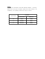
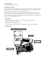
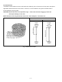
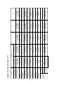
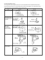
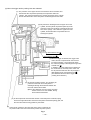
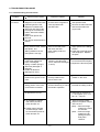
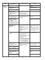
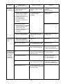
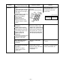
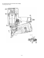
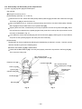
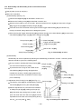
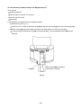
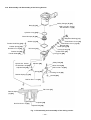
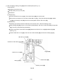
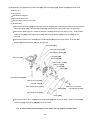
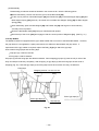
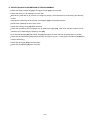
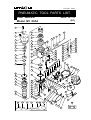
MODEL
NV 83A2
POWER TOOLS
COIL NAILER
NV 83A2
TECHNICAL DATA
AND
SERVICE MANUAL
N
LIST No. E007
Oct. 2002
SPECIFICATIONS AND PARTS ARE SUBJECT TO CHANGE FOR IMPROVEMENT
REMARK:
Throughout this TECHNICAL DATA AND SERVICE MANUAL, a symbol(s)
is(are) used in the place of company name(s) and model name(s) of our
competitor(s). The symbol(s) utilized here is(are) as follows:
Competitors
Symbols Utilized
Company Name
Model Name
R
SENCO
SCN65
Y
PASLODE
P350C
P
BOSTITCH
N80CB
CONTENTS
Page
1. PRODUCT NAME ..................................................................................................................... 1
2. MARKETING OBJECTIVE ....................................................................................................... 1
3. APPLICATIONS ........................................................................................................................ 1
4. SELLING POINTS .................................................................................................................... 1
5. SPECIFICATIONS .................................................................................................................... 3
5-1. Specifications ........................................................................................................................... 3
5-2. Nail Selection ........................................................................................................................... 4
5-3. Nail Driving Force .................................................................................................................... 5
5-4. Optional Accessories ............................................................................................................... 6
6. COMPARISONS WITH SIMILAR PRODUCTS ........................................................................ 7
7. PRECAUTIONS IN SALES PROMOTION ............................................................................... 8
7-1. Instruction Manual ................................................................................................................... 8
7-2. Warning Label .......................................................................................................................... 8
7-3. Related Laws and Regulations ................................................................................................ 9
7-4. Precautions in Operation ......................................................................................................... 9
8. MECHANISM AND OPERATION PRINCIPLE ....................................................................... 10
8-1. Mechanism ............................................................................................................................ 10
8-2. Interchangeability of Parts ...................................................................................................... 11
8-3. Operation Principle ................................................................................................................ 13
9. TROUBLESHOOTING GUIDE ............................................................................................... 17
9-1. Troubleshooting and Correction ............................................................................................. 17
9-2. Possible Causes and Corrections of Air Leakage .................................................................. 22
10. DISASSEMBLY AND REASSEMBLY .................................................................................. 25
10-1. General Precautions in Disassembly and Reassembly ....................................................... 25
10-2. Disassembly and Reassembly of the Output Section .......................................................... 26
10-3. Disassembly and Reassembly of the Control Valve Section ............................................... 28
10-4. Disassembly and Reassembly of the Magazine Section ..................................................... 29
10-5. Disassembly and Reassembly of the Driving Section ......................................................... 32
10-6. Grip Rubber ......................................................................................................................... 36
11. INSPECTION AND CONFIRMATION AFTER REASSEMBLY ............................................ 37
12. STANDARD REPAIR TIME (UNIT) SCHEDULES ............................................................... 38
Assembly Diagram for NV 83A2
1. PRODUCT NAME
Hitachi 83 mm Coil Nailer, Model NV 83A2
2. MARKETING OBJECTIVE
The current Model NV 83A is a well-reputed 3-1/4 coil nailer suitable for framing works. However, the coil nailer
market is becoming increasingly competitive. The newly introduced Model NV 83A2 is developed by making
minor changes to the current Model NV 83A to meet the market demands.
The output section is common to that of the Model NV 83A featuring good driving response. In addition, the
Model NV 83A2 is equipped with a tool-less nailing depth adjuster, pop-out magazine, non-slip rubber, etc. to
meet the market demands. Applicable nails are the same as those of the Model NV 83A. The Model NV 83A2
weighs only 3.7 kg (same as the Model NV 83A).
3. APPLICATIONS
Construction of wooden work such as floor and wall framing, roof decking and subflooring
Mobile and modular home construction
Making wooden boxes, palletes, and drums
Packing operations in manufacturing plants, and other types of packing and crating work in general
4. SELLING POINTS
Quick driving 2-valve cylinder drive system
Grip rubber
Easy top load
pop-out magazine
Tool-less adjuster
--- 1 ---
(1) Output section
The basic construction is the same as that of the Model NV 83A except the 2-valve cylinder drive system that
is well reputed for quick driving is adopted.
(2) Adjuster
While the Model NV 83A requires a wrench to adjust the nailing depth, the Model NV 83A2 requires no tool for
adjustment. Amount of adjustment is about 4.5 mm (0.177").
Flush
Shallow
Too deep
Too shallow
Deep
Adjuster
(3) Magazine
While the Model NV 83A is equipped with a bottom loading magazine, the Model NV 83A2 is equipped with
the "pop-out magazine" that allows easy nail loading from the top of the magazine thanks to the tilting nail
holder. The magazine can be opened/closed just by the nail guide operation. (The Model NV 83A requires
operation of both the nail guide and the latch at the rear of the magazine.)
(4) Handle grip
Thanks to the adoption of the grip rubber that is common to the Model NR 83AA2, the handle grip of the Model
NV 83A2 is more durable than that of the Model NV 83A.
--- 2 ---
5. SPECIFICATIONS
5-1. Specifications
NV 83A2
Model
Driving system
Reciprocating piston type
Operating pressure
5 --- 8.5 kgf/cm2 (70 --- 120 psi, 4.9 --- 8.3 bar) (Gauge pressure)
Driving speed
Min. 3 pcs./sec.
Weight
3.7 kg (8.2 lbs.)
Dimensions
(Length x height x width)
290 mm x 348 mm x 135 mm
(11-13/32" x 13-11/16" x 5-13/32")
Nail feed system
Reciprocating piston type
Nail capacity
200 --- 300 nails (1 coil)
Air consumption
2.4 ltr/cycle at 7 kgf/cm2 (.085 ft3/cycle at 100 psi) (2.4 ltr/cycle at 6.9 bar)
Air inlet
3/8 NPT thread
Packaging
Corrugated cardboard box
Package dimensions
(Length x height x width)
396 mm x 143 mm x 366 mm
(15-19/32" x 5-5/8" x 12-39/64")
Standard accessories
Hex. bar wrench for M5 screw (Code No. 944458) .................................... 1
Hex. bar wrench for M6 screw (Code No. 944459) .................................... 1
Hex. bar wrench for M8 screw (Code No. 872422) .................................... 1
Eye protection (Code No. 875769) ............................................................. 1
Optional accessories
Sequential trip mechanism kit (single-shot) (Code No. 876762)
Pneumatic tool lubricant (1 oz oil feeder) (Code No. 877153)
Pneumatic tool lubricant (4 oz oil feeder) (Code No. 874042)
Pneumatic tool lubricant (1) (Code No. 876212)
--- 3 ---
5-2. Nail Selection
The Model NV 83A2 utilizes common round-head nails collated by wire or sheet into coils from 200 to 300 pieces.
Applicable nail dimensions are shown below. However, it is recommended to use genuine HITACHI nails to
ensure satisfactory driving quality.
CAUTION: Ensure that nails are as specified in Fig. 1. Other nails will cause clogging of nails and
subsequent damage to the nailer.
NOTE: Aluminum nails may bend when driven into a hard workpiece. Test before use.
Wire-collated nails
Max.
Min.
2.5 mm
(.099")
Fig. 1 Dimensions of nails
--- 4 ---
7.2 mm
(.283")
83 mm (3-1/4")
50 mm (2")
6 mm
(.236")
3.3 mm
(.131")
5-3. Nail Driving Force
Fig. 2 shows by type of wood and nail, the nailer output energy provided by the supply pressure and the nailing
energy required for driving the nail flush. Air pressure which exceeds the intersecting point between the nailer
output energy and the nailing energy required for driving the nail allows the nail to be fully driven.
For example, when driving a nail of 3.3 mm dia. by 83 mm length (0.131" x 3-1/4") into nine sheets of 12 mm
plywood (108 mm thick) with the Model NV 83A2, a pressure of about 7.0 bar (7.1 kgf/cm2, 102 psi) allows the
nailer to drive the nail flush with the wood surface. A pressure beyond this value causes the nail head to be driven
below the wood surface. Fig. 2 should be used as reference data because those values vary depending on the
type, moisture content, and grain of wood.
Y
NV 83A2 NV 83A, R, P
NV 83A2
Fig. 2 Required nailing energy and nailer output energy
--- 5 ---
5-4. Optional Accessories
Sequential trip mechanism kit (Single shot) (Code No. 876762)
A sequential trip mechanism kit is provided as an optional accessory for the Model NV 83A2. By using this
optional accessory, a nail is driven by pressing the pushing lever first against a workpiece and then pulling the
trigger (single-shot operation), and no nail is driven when pulling the trigger first and then pressing the pushing
lever against a workpiece. Please recommend the sequential trip mechanism kit to the customers who want to
use it. Salespersons must instruct the customers to read the Handling Instructions attached to the sequential trip
mechanism kit and also the Handling Instructions of the Model NV 83A2 thoroughly for correct use.
--- 6 ---
--- 7 ---
8.4 lbs. (3.8 kg)
8.2 lbs. (3.7 kg)
8.2 lbs. (3.7 kg)
Weight
2.5 mm -- 3.3 mm
(0.098" -- 0.120")
50 mm -- 83 mm
(2" -- 3-1/4")
2.5 mm -- 3.3 mm
(0.098" -- 0.120")
50 mm -- 83 mm
(2" -- 3-1/4")
Shank dia.
Length
38 mm -- 83 mm
(1-1/2" -- 3-1/4")
2.5 mm -- 3.8 mm
(0.098" -- 0.150")
38 mm -- 83 mm
(1-1/2" -- 3-1/4")
2.5 mm -- 3.3 mm
(0.098" -- 0.120")
Wire
Wire
Wire
Wire
Applicable
nails
Rubber
Rubber
Rubber
Racket grip
Rubber
Handle grip
50 mm -- 90 mm
(2" -- 3-1/2")
2.5 mm -- 3.3 mm
(0.098" -- 0.120")
Wire
1-valve
1-valve
1-valve
2-valve
2-valve
Trigger valve
Collation
Tool not required
Tool required
None
Top loading
(Plastic)
225 --- 275 nails
2.5 ltr/cycle
(0.089 ft3/cycle)
With wrench
Top loading
(Plastic)
225 --- 275 nails
2.7 ltr/cycle
(0.096 ft3/cycle)
327 mm x 359 mm x 111 mm
(12-7/8" x 10-9/64" x 4-3/8")
8.2 lbs. (3.7 kg)
4.9 --- 8.3 bar
(5 --- 8.5 kgf/cm2)
(70 --- 120 psi)
R
Tool not required
Driving depth
adjustment mechanism
Top loading
(Plastic)
Magazine type
(Material)
Top loading
(Plastic)
225 --- 300 nails
200 --- 300 nails
200 --- 300 nails
Nail capacity
Bottom loading
(Plastic)
2.6 ltr/cycle
(0.093 ft3/cycle)
2.2 ltr/cycle
(0.078 ft3/cycle)
2.2 ltr/cycle
(0.078 ft3/cycle)
Air consumption
at 7 kgf/cm2 (100 psi)
Dimensions
(L x H x W)
8.4 lbs. (3.8 kg)
4.9 --- 8.3 bar
(5 --- 8.5 kgf/cm2)
(70 --- 120 psi)
Y
290 mm x 348 mm x 135 mm 290 mm x 348 mm x 135 mm 306 mm x 330 mm x 141 mm 330 mm x 325 mm x 132 mm
(11-13/32" x 13-11/16" x 5-13/32")
(11-13/32" x 13-11/16" x 5-13/32")
(12-3/64" x 13" x 5-35/64")
(13" x 9-51/64" x 5-13/64")
4.9 --- 6.9 bar
(5 --- 7 kgf/cm2)
(70 --- 100 psi)
4.9 --- 8.3 bar
(5 --- 8.5 kgf/cm2)
(70 --- 120 psi)
4.9 --- 8.3 bar
(5 --- 8.5 kgf/cm2)
(70 --- 120 psi)
P
Operating pressure
Model name
NV 83A
HITACHI
NV 83A2
Maker
6. COMPARISONS WITH SIMILAR PRODUCTS
7. PRECAUTIONS IN SALES PROMOTION
In the interest of promoting the safest and most efficient use of the Model NV 83A2 Nailer by all of our customers,
it is very important that at the time of sale the salesperson carefully ensures that the buyer seriously recognizes
the importance of the contents of the Instruction Manual, and fully understands the meaning of the precautions
listed on the Warning Label attached to each tool.
The Model NV 83A2 Nailer is designed for continuous nail driving. At time of sale, the salesperson must inform
the customer that the sequential trip mechanism kit which can change the Model NV 83A2 to a single-shot nailer
is optionally available, and recommend it to the customers who want to use it. Refer to the leaflet attached
together with the Instruction Manual for details.
7-1. Instruction Manual
Although every effort is made in each step of design, manufacture, and inspection to provide protection against
safety hazards, the dangers inherent in the use of any pneumatic tool cannot be completely eliminated.
Accordingly, general precautions and suggestions for use of pneumatic tools, and specific precautions and
suggestions for the use of the pneumatic nailer are listed in the Instruction Manual to enhance the safe, efficient
use of the tool by the customer.
Salespersons must be thoroughly familiar with the contents of the Instruction Manual to be able to offer
appropriate guidance to the customers during sales promotion.
7-2. Warning Label
Each Model NV 83A2 unit is provided with a Warning Label (illustrated below) which lists basic safety precautions
in its use. Carefully ensure that customers fully understand and follow these precautions before using the tool.
PROTECTION
--- 8 ---
7-3. Related Laws and Regulations
As nailers and staplers are designed to instantaneously drive nails and staples, there is an ever-present danger of
misfiring and subsequent possible serious injury. Accordingly, close attention in handling is absolutely necessary
at all times. Carefully ensure that the customer is fully aware of the precautions listed in the Instruction Manual
provided with each unit.
While there are no specific safety regulations, there are related items in various general safety regulations with
which the salespersons should be familiar in order to properly advise the customer. Please check your national
and/or local regulations for applicable items. Some applicable items are outlined below.
The U.S.A:
OSHA
1926.102 Eye and face protection
1926.302 Power-operated hand tools
ANSI SNT-101-1993
Portable, Compressed-Air-Actuated,
Fastener Driving Tools-Safety Requirements for
7-4. Precautions in Operation
(1) Pay special attention to the pressure, capacity and piping of the air compressor in order to keep the air
pressure supplied to the Model NV 83A2 within the range from 5 kgf/cm2 (70 psi, 4.9 bar) to 8.5 kgf/cm2
(120 psi, 8.3 bar). Otherwise, ill effect may be given to the performance, service life and safety of the Model
NV 83A2. (Be sure to install a regulator when using a high-pressure air compressor whose set pressure is
10 kgf/cm2 (140 psi, 9.8 bar) or more. In this case, adjust the air pressure at 8.5 kgf/cm2 (120 psi, 8.3 bar) or
less.)
(2) If dust in the compressed air settles on the sliding portion, the Model NV 83A2 will not operate properly.
Lubrication is effective to remove dust and also to prolong the service life of the Model NV 83A2 keeping good
performance. It is recommended to lubricate the Model NV 83A2 daily. Supply 5-10 drops of lubricant into the
air plug on the Model NV 83A2.
When not in use for an extended period, supply lubricant and perform idle driving two or three times to
lubricate the inside, then apply a thin coat of the lubricant to the steel parts to avoid rusting.
Usable lubricant is specified in the following table. Please recommend the customers to use Hitachi nailer/
tacker oil.
Type of oil
Hitachi Pneumatic Tool Lubricant
Brand or product name
Shell sliding oil, Tonna S32
(Old Tonna T32);
Code No. 877153 (1 oz. oil feeder)
Code No. 874042 (4 oz. oil feeder)
Code No. 876212 (1L (1 quart) can)
(3) Be sure to drain the tank of the compressor securely to prevent deteriorated performance or malfunction of the
Model NV 83A2 due to rusting.
(4) Instruct the customers (especially the heavy users) to perform inspection and maintenance securely.
--- 9 ---
8. MECHANISM AND OPERATION PRINCIPLE
8-1. Mechanism
As illustrated in Fig. 3, the Model NV 83A2 can be generally divided into four sections:
output section, control valve section, driving section and magazine section.
Although the output section and the valve section are basically common to those of the Model NV 83A, most of
the parts of the driving section and the magazine section have been newly designed.
Primary differences from the Model NV 83A are described below.
Output section ................... The handle employs a grip rubber (Model NV 83A grip tape).
Driving section .................... The tail cover, nail guide shaft, etc. have been newly designed to adopt the toolless adjuster.
Magazine section ................ Most of the parts of the magazine section have been newly designed to make the
magazine top-loading type.
Exhaust
Valve [9]
Exhaust vent
Accumulator
Head Cap and
Gasket Set [10]
Output section
Safety valve portion
Exhaust Cover [4]
Control valve section
Trigger valve portion
Piston (H) [12]
Cap [46]
Air inlet
Cylinder Ring [19]
Cylinder [17]
Driver blade
Magazine section
Air return chamber
Piston Bumper
(B) [29]
Driving section
Adjuster [39]
Magazine
Cover [84]
A
Tail Cover [31]
Nail Holder [87]
Magazine [81]
Section A - A
Guide Lock [97]
Pushing Lever [54]
Feeder Set [35]
Fig. 3 Construction
--- 10 ---
Nail Guide [95]
Feeder Piston [70]
8-2. Interchangeability of Parts
The driving section and the magazine section are not interchangeable between the Model NV 83A2 and the
NV 83A because these sections of the Model NV 83A2 have been newly designed. The output section and the
control valve section are interchangeable except the following parts.
Part
NV 83A2
NV 83A
Pisotn Bumper (B) [29]
8.3 mm dia.
10 mm dia.
Large hole dia.
Hex. Socket Hd. Bolt
(W/Flange) M6 x 45 [1]
(for mounting the Top
Cover [2])
Hex. Socket Hd.
Bolt (W/Flange)
M6 x 45 [1]
M6 x25
Spring washer
Top Cover [2]
Hex. Socket Hd. Bolt
(W/Sp. Washer)
M6 x 25 [3]
(for mounting the
Exhaust Cover [4])
Hex. Socket Hd. Bolt
(W/Sp. Washer)
M6 x 25 [3]
M6 x25
Spring washer
Exhaust Cover [4]
Tail Cover [31]
Boss
Hole
Tail Cover [31]
Nail Guide [95]
Flat
--- 11 ---
Part
NV 83A2
NV 83A
Pushing Lever [54]
Bent.
Welded.
Cover [105]
--- 12 ---
8-3. Operation Principle
(1) When the compressed air source (air hose) is connected to the nailer:
Air pressure is applied to the lower surfaces of the
flanges located at the center portion of the cylinder,
forcing the cylinder upward. The compressed air is
thereby blocked from the upper end of the cylinder,
and no pressure is applied to the Piston.
The accumulator is filled with
compressed air.
The trigger and pushing lever are not
operated, and remain closed.
The exhaust vents are open, and no air
pressure is applied to the valve and feed
piston air passage.
Fig. 4
--- 13 ---
(2) When the trigger and pushing lever are operated:
Cylinder ring
(D) Although air pressure is applied
to both the upper and lower
surfaces of the cylinder, the
cylinder is forced downward due
to the larger effective area of the
upper surface.
Accordingly, the upper portion of
the cylinder is opened, and the
compressed air forces the
piston downward.
(D) Compressed air is applied
to the upper side of the
exhaust valve, forcing it
downward and closing
the exhaust vent.
(B) When the trigger and pushing lever are
operated simultaneously, the safety
valve and trigger valve are opened.
(A) The trigger and pushing lever are operated
simultaneously.
(Note)
If either the trigger or pushing lever are
operated individually, compressed air will
not enter the valve air passage, and the
nailer will not function.
(C) When the trigger and pushing
lever are operated
simultaneously, the exhaust
vents are closed.
(E) The air pressure applied to the left-side surface of the feed piston
overcomes the spring force on the right-side, and moves the feed
piston to the right. The feeder then catches the next nail.
(E) As the piston moves downward, the air below the piston
is forced into the return air chamber.
(F) When the piston passes the middle vent, some of the air pressure passes into the
return air chamber. This supplies auxiliary air to ensure complete return of the piston.
When the cylinder moves down,
compressed air from the head cap
section enters the passage to the
feed piston.
Fig. 5
--- 14 ---
(3) If the trigger and pushing lever are kept pressed:
Air pressure is applied in the shaded areas
in the illustration, and each component is
held in the position illustrated.
If the operator's grip is loosened, air will leak.
As there is no O-ring installed here, a very small
amount of air will leak from the slight clearance
between the components.
The lower surface of the Piston contacts
the Piston Bumper and prevents air
leakage. If the upper surface of the
damper is damaged, some air will leak.
Fig. 6
--- 15 ---
(4) When the trigger and/or pushing lever are released:
(C) The pressure on the upper surface of the exhaust valve is released, and
the exhaust valve is pushed upward by the air pressure within the
cylinder. This opens the exhaust vent, and the air pressure in the cylinder
and the left-side surface of the feed piston are discharged from the nailer.
(B) Air pressure is discharged from the upper end of the
cylinder, and the cylinder is pushed upward by the air
pressure on the lower surfaces of the flanges and the
force of the springs. This closes the upper end of the
cylinder, and blocks further compressed air from
entering the cylinder.
Valve exhaust vent I
Valve exhaust vent II
(A) When the trigger is released, the trigger valve
closes, and the compressed air does not flow
into the air passage. The air pressure within
the valve air passage is discharged through valve
exhaust vent I .
In addition, when the pushing lever is lifted from
the wood surface, the safety valve closes and
the air pressure within the valve air passage is
discharged through valve exhaust vent II .
(The illustration shows both the trigger and
pushing lever released.)
(E) At the time the piston returns, any remaining air
pressure at the lower end of the piston is
discharged through the clearance between the
tail cover and the driver blade.
(Note) If the clearance were any larger, the piston
would not return: if it were smaller, driving
force would be decreased.
(F) As the air pressure at the left-side surface of the feed piston is reduced, spring
force at the right-side surface moves the feed piston toward the ejecting gate, and
the next nail is fed into firing position by the feeder.
(D) When the air pressure at the upper side of the piston is reduced, the
air pressure within the return air chamber pushes the piston upward.
Fig. 7
--- 16 ---
9. TROUBLESHOOTING GUIDE
9-1. Troubleshooting and Correction
Problem
1) Nails cannot
be driven.
(
Possible cause
: Most-common cause)
<Nails>
Magazine is not loaded with
specified genuine nails.
Magazine is loaded with
abnormal nails (bent nails,
too large or too small nail
heads, abnormal collation,
others).
Nails or link pieces are
jammed.
Link pieces are deformed or
broken.
<Driving section: Nose, feeder,
feed piston, etc.>
Sliding resistance of the
feed piston is too high.
Nail guide face of the nose
is abnormal (deformed,
burrs or damaged).
Spring or feeder spring is
abnormal (damaged or
fatigued).
Feeder is abnormal
(damaged or worn).
Inspection method
Remedy
Check that the magazine is
correctly loaded with
specified nails.
Use specified nails.
Remove the abnormal nails
and load the nailer with
proper nails.
Remove the feed piston
and check the feed
piston sliding surface of
the nose.
Apply grease to the sliding
surface.
Polish the scratched portion
with sandpaper. Replace
the parts.
Check that the driving
section is not abnormal
(burrs, deformed, damaged
or worn).
Deburr the nail guide face.
Correct the deformed parts.
Replace the abnormal parts.
Nails are not correctly
loaded in the groove of the
nose.
Check that nails are
correctly loaded in the
groove of the nose.
Load nails in the correct
position in the nose.
Dust sticks to the feeder
sliding portion of the nose,
or lubrication is needed.
Open the nail guide and
perform idle driving to check
the feeder's operation.
Remove dust and then
lubricate the sliding surface.
Adjust the air pressure to
5 --- 8.5 kgf/cm2 (4.9 --- 8.3
bar, 70 --- 120 psi).
Air pressure is too low.
Air passage is clogged
with broken pieces of
piston bumper, etc.
Remove foreign matter.
Replace the piston bumper
with new one.
Body ••• Remove foreign
matter in the return
air chamber.
Nose ••• Remove foreign
matter in the air
passage and the
feed piston
chamber.
Feeder piston chamber
contains foreign matter
such as broken pieces of
piston bumper, etc.
--- 17 ---
Problem
1) Nails cannot
be driven.
(continued)
(
Possible cause
: Most-common cause)
Inspection method
Remedy
Air leaks from Gasket (A).
Tighten screws and replace
gaskets.
O-rings are worn or
deformed.
Replace the O-rings.
O-rings need lubrication.
Apply grease or lubricate.
<Nail guide section>
Nail guide face is abnormal
(deformed, burrs or
damaged).
Dust sticks to the inside of
the nail guide groove, or
lubrication is needed.
Check that the nail guide is
not abnormal (worn,
deformed, damaged, etc.).
Correct or replace the parts.
Check the operation of main
nail stopper and sub nail
stopper.
Rremove dust and then
lubricate.
Spring is abnormal
(missing, damaged or
fatigued).
The claw ridge section of
the nail stopper is abnormal
(damaged, worn or burrs).
<Magazine section>
<Pushing lever>
Magazine
Safety belt is not adjusted
properly.
<Output section: piston,
driver blade, etc.>
Air pressure is too low.
Replace the abnormal parts.
Check that a nail does not
catch on another nail in the
magazine.
Check that a nail does not
catch on some part of the
magazine.
Check the height of the nail
holder.
Collate the nails correctly
and reload the nailer with
them.
Remove burrs or deformed
part. Replace the parts.
Adjust the height of the nail
holder correctly.
Check that the distance
between the lower end of the
nose and the lower end of
the pushing lever is
6.5 0.5 mm (0.256 0.020")
under the following
conditions.
Pull up safety plunger (B)
until it contacts plunger (A).
Pull up the pushing lever
until safety plunger (B)
contacts the safety bolts.
Readjust the safety bolt
according to 10-3-(2).
Open the nail guide and
perform idle driving to check
that the driver blade is
returned.
Adjust the air pressure to
5 --- 8.5 kgf/cm2 (4.9 --- 8.3
bar, 70 --- 120 psi).
Piston O-ring is abnormal
(worn or damaged).
Replace the piston O-ring.
Piston bumper is abnormal.
Replace the piston bumper.
Reassemble or replace the
parts.
Cylinder ring is abonrmal
(removed, deformed or
damaged).
Driver blade is abnormal
(deformed, burrs or damaged).
Correct or replace the parts.
--- 18 ---
Problem
1) Nails cannot
be driven.
(continued)
(
Possible cause
: Most-common cause)
Inspection method
Cylinder inside surface is
abnormal (packed with
dust, or worn).
Check that nails can be
driven at 5 kgf/cm2 (4.9 bar,
70 psi).
Remove dust and then
lubricate.
Replace the part.
Sliding surface between the
cylinder and the cylinder
guide or sliding surface
between the cylinder and
the cylinder plate is
abnormal (seized or
damaged, or lubrication is
needed).
Perform idle driving to
check the driving
operation.
Replace the part.
Apply grease.
<Control valve section>
Trigger plunger, plunger (A),
safety plunger (B), trigger
valve bushing, valve
bushing or urethane ball (C)
is abnormla (seized or
damaged).
2) Nails are
driven but
bent.
3) Nails cannot
be driven into
the workpiece
completely:
the heads
cannot be
made flush.
Remedy
Replace the abnormal part.
O-ring or sliding surface is
worn or needs lubrication.
Disassemble the control
valve section and check the
O-rings.
Replace the abnormal part.
Apply grease.
Nails are not completely
fed into the injection port.
Unspecified nails are used.
See item 1).
See item 1).
Driver blade is worn.
Check that the driver blade
tip is not abnormally worn.
Replace the part.
Workpiece is too hard.
Check if a nail is bent even
when driven into soft wood.
Nailer cannot be used
because the material is
beyond its applicable range.
Adjuster is incorrectly set.
Turn the adjuster to the
deepest driving position and
then drive nails.
Set the adjuster to the
optimum position.
Adjust air pressure to
5 --- 8.5 kgf/cm2 (4.9 --- 8.3
bar, 70 --- 120 psi).
Air pressure is too low.
Workpiece is too hard.
Driver blade is worn.
Check if a nail is bent even
when driven into soft wood.
Nailer cannot be used
because the material is
beyond its applicable range.
Perform idle driving to check
the driver blade is pfojected
from the nose tip.
Replace the part.
--- 19 ---
Problem
3) Nails cannot
be driven into
the workpiece
completely:
the heads
cannot be
made flush.
(continued)
Possible cause
: Most-common cause)
Inspection method
Remedy
Disassemble the output
section and check inside
and outside surfaces of the
O-ring and the cylinder for
abnormality.
Replace the abnormal part.
Check for shortage of
grease on the sliding
surface of the O-ring.
Apply grease.
Exhaust valve is abnormal or
short of oil (worn or
scratches on seat side).
Disassemble the exhaust
valve section and check for
abnormality or shortage of
oil.
Apply grease.
Replace the abnormal part.
Safety belt is not adjusted
properly.
Check that the distance
between the lower end of
the nose and the lower end
of the pushing lever is
6.5 0.5 mm (0.256
0.020") under the following
conditions.
Pull up plunger (B) until it
contacts plunger (A).
Pull up the pushing lever
until plunger (B) contacts
the safety bolt.
Readjust the safety bolt
according to 10-3-(2).
(
Piston O-ring is abnormal
(worn or damaged).
Cylinder inside surface is
abnormal (worn or rough).
Cylinder O-ring is abnormal
(worn or damaged).
Sliding surface of the
circmference of the cylinder
is abnormal (worn or
damaged).
Short of oil on both inside
and outside surfaces of the
cylinder (worn or damaged).
--- 20 ---
Possible cause
: Most-common cause)
<Nails>
Unspecified nails are used.
Abnormal nails are mixed.
Nail heads are too large or
too small.
Collating wires are abnormal
(broken, welding failed,
deformed or welding
position failed).
Collating wires are
deformed (deformed in
collation angle or collation
pitch).
Inspection method
Remedy
Check if the specified nails
are used.
Check the nails as follows.
Use specified nails.
Remove the abnormal nails
and load the nailer with
proper nails.
(1.4
76)
19 (
0.74
8)
4) Nails jam.
(
37.5
Problem
16˚
Unit: mm (inch)
D
d
6 --- 7.19
2.5 --- 3.33
(0.236 --- 0.283) (0.099 --- 0.131)
<Body: Nail feeding is
incomplete.>
Feeder is worn and the
sliding section is abnormal.
Nail guide face of the nose
or the sliding section of the
feeder is abnormal
(deformed, burrs or
damaged).
Feed spring or feeder spring
is abnormal (damaged,
fatigued or removed).
Open the nail guide and
check the position of the
feeder claw. Check that the
feeder claw holds a nail, and
the first nail is positioned in
the injection port. (Check
that the second claw holds
the nail shaft and feeds it.)
Replace the abnormal part.
<Body: Nail guide section>
Nail guide section is
abnormal.
See item "1) Nail guide
section".
See item "1) Nail guide
section".
<Driver blade is not returned
completely.>
See item "1) Output
section: piston, driver
blade, etc.".
Perform idle or actual
driving to check if the driver
blade is returned
completely.
See item "1) Output section:
piston, driver blade, etc.".
--- 21 ---
9-2. Possible Causes and Corrections of Air Leakage
Air leakage repair location
A
B
G
E
F
C
A
A
A --- A
D
H
--- 22 ---
I
Inspection priorities:
In the table below, possible causes of air leakage and their repair procedures are marked in accordance with the
likelihood of possible failure.
(1) First priority items are marked with an asterisk ( ).
(2) Second priority items (seal portions) are marked with a double circle (
(3) Remaining items are marked with a single circle (
name and location.)
).
). (See Parts List and exploded assembly diagram for part
Cause
Air leak part
When trigger valve/safety valve are OFF
A
Exhaust vent
B
Exhaust cover
Cylinder [17] does not return.
Swollen Cylinder O-ring [16] (Use of
unsuitable oil causes swelling. Advise the
customer to use Shell Tonna Oil T32.)
Deformed Cylinder [17] or Cylinder Guide [22].
Yielded or broken Cylinder Spring [20].
Defective Head Cap and Gasket Set [10]
(worn rubber portion or broken)
Broken Gaskets (C) (F) [8] [6]
Loose Hex. Socket Hd. Bolt (W/Flange)
M6 x 45 [1]
Broken Exhaust Cover [4]
E
Trigger valve
F
Safety valve
G
Cap
Defective Exhaust Valve
[9] (worn, deformed, or
broken)
Deformed Tail Cover [31]
Loose Nylock Hex. Socket
Hd. Bolt M8 x 22 [37]
Nose
D
When trigger valve ON/
safety valve OFF
Loose Hex. Socket Hd. Bolt (W/Sp. Washer)
M6 x 25 [3]
Broken Gasket (B) [5]
Damaged seal surfaces of Body (B) [27] and
Exhaust Cover [4]
C
Nose
When trigger valve/
safety valve are ON
Damaged Cylinder O-ring [18] or O-ring of
Cylinder Guide [22] (worn, deformed or
broken)
Defective Body (B) [27] (worn, corroded or
deformed)
Broken or cracked
Piston Bumper (B) [29]
Deformed Piston (H)
[12]
Deformed Tail Cover [31]
Defective Plunger O-ring
[58] (worn, deformed or
broken)
Defective outside
O-ring [59] of Trigger
Valve Bushing [67]
Defective Urethane Ball (C) D7.14 [65]
(damaged or deformed)
Defective ball sheet surface of Trigger Valve
Bushing [67] (damaged, deformed or worn)
Defective Valve Packing [64] (damaged,
deformed or broken)
Soiled or damaged valve packing sheet
surface of Body (B) [27]
Incursion of foreign materials
Defective Gaskets (C) (F) [8] [6] (damaged or
yielded)
Deformed or broken Gasket (G) [23]
Defective O-ring (S-90) [13] or Cylinder Oring [14] of the Cylinder Plate [15] (worn,
deformed or broken)
Defective Cylinder O-ring [16] (worn,
deformed or broken)
Loose Hex. Socket Hd. Bolt M5 x 18 [47]
Broken Gasket (D) [45]
Defective seal surface of the Body (B) [27] or
Cap [46]
--- 23 ---
Air will leak slightly from
the lower portion due to
construction.
Defective outside O-ring
[59] of the Valve Bushing
[60] (worn, deformed or
broken)
Defective plunger O-ring
[58] (worn, deformed or
broken)
Defective Plunger Spring
[56] (deformed or broken)
Defective safety Valve
Bushing [60] (deflected,
deformed or broken)
Cause
Air leak part
When trigger valve/safety valve are OFF
Between feed
piston cover and
nose
When trigger valve ON/
safety valve OFF
Defective O-ring [69] of
Feed Piston [70] (worn,
deformed or cut)
Defective Feed Piston
[70] sliding portion
(damaged, deformed or
broken)
H
Feed piston
I
When trigger valve/
safety valve are ON
Defective seal surface of Tail Cover [31] and
Feed Piston Cover [75]
Defective O-ring [71] of Feed Piston [70]
(worn, deformed or cut)
Slight amount of air is always leaked out of the Feed Piston Cover [75] structurally.
--- 24 ---
10. DISASSEMBLY AND REASSEMBLY
The items particularly necessary for disassembly and reassembly are described below. The [Bold] numbers in
the descriptions below correspond to the item numbers in the Parts List and exploded assembly diagram.
[CAUTION]
Before disassembly or reassembly, be sure to remove all nails and disconnect the air hose from the
nailer (with your finger released from the trigger) to exhaust all the compressed air.
10-1. General Precautions in Disassembly and Reassembly
Apply grease (Nippeco SEP-3A, Code No. 930035) to the O-rings and O-rings' sliding portions.
When installing the O-rings, be careful not to damage the O-rings and prevent dirt entry.
Oil required: Hitachi pneumatic tool lubricant
1 oz (30 cc) oil feeder (Code No. 877153)
4 oz (120 cc) oil feeder (Code No. 874042)
1 quart (1 ltr) can (Code No. 876212)
If Gasket (B) [5] is damaged, replace it and check that no air is leaking.
Be especially careful to prevent the entry of foreign particles into the control valve section.
Tightening torque for each part
Tightening torque
N•m (kgf•cm, ft-lb)
Bolt
Nylock Hex. Socket Hd. Bolt M8 x 22 ........................... [37]
30.4
2 (310
Hex. Socket Hd. Bolt (W/Flange) M6 x 45 .................... [1]
12.7
0.8 (130
Hex. Socket Hd. Bolt (W/Sp. Washer) M6 x 25 ............. [3]
9.8
0.8 (100
Hex. Socket Hd. Bolt M5 x 18 ....................................... [47]
8.3
0.5 (85
5, 6.1
0.4)
Hex. Socket Hd. Bolt M5 x 20 ....................................... [100]
8.3
0.5 (85
5, 6.1
0.4)
Seal Lock Hex. Socket Hd. Bolt M5 x 10 ...................... [76]
8.3
0.5 (85
5, 6.1
0.4)
Machine Screw M5 x 25 ................................................ [44]
2.9
0.37 (30
Seal Lock Hex. Socket Hd. Bolt M4 x 8 ........................ [107]
4.4
0.3 (45
--- 25 ---
20, 22.4
1.4)
8, 9.4
0.6)
8, 7.2
0.6)
3.8, 2.2
3, 3.3
0.3)
0.2)
10-2. Disassembly and Reassembly of the Output Section
(1) Piston (H) [12], Cylinder [17] and related parts
Tool required:
Hexagon bar wrench (5 mm)
(a) Disassembly (See Figs. 10, 11 and 12.)
Remove the four Hex. Socket Hd. Bolts (W/Sp. Washer) M6 x 25 [3], and take off the Exhaust Cover [4].
The Piston (H) [12] can then be taken out.
Next, as illustrated in Fig. 9, screw two of the previously removed Hex. Socket Hd. Bolt (W/Sp. Washer)
M6 x 25 [3] into the provided holes on the Cylinder Plate [15].
Gripping these two bolts, simultaneously turn and pull upward to remove the Cylinder Plate [15]. When
this has been accomplished, the Cylinder [17] and other parts which make up the output section can be
removed, as illustrated in Fig. 10.
If it is difficult to remove the Cylinder [17], remove the Tail Cover [31] by referring para.10-5 procedures,
and push out the Cylinder [17] from the lower part of the main body.
(b) Reassembly
Reassembly can be accomplished by following the disassembly procedures in reverse. However, special
attention should be given to the following items.
Confirm that Gasket (G) [23] is reassembled.
Check that the Base Washer [21] is securely and properly mounted to its position in the Body (B) [27].
Then mount the other parts.
Hex. Socket Hd. Bolt
(W/Sp. Washer) M6 x 25 [3]
Exhaust Cover [4]
Cylinder Plate [15]
Hex. Socket Hd. Bolt
(W/Sp. Washer) M6 x 25 [3]
Piston (H) [12]
Threaded hole
for M6 bolts
Cylinder [17]
Cylinder Plate [15]
Gasket (B) [5]
Body (B) [27]
Fig. 8
Fig. 9
--- 26 ---
O-Ring [11]
Cylinder Spring [20]
Piston (H) [12]
Base Washer [21]
Cylinder Guide [22]
Gasket (G) [23]
Cylinder Plate [15]
Body (B) [27]
Cylinder [17]
Cylinder Ring [19]
Fig. 10
(2) Head Cap and Gasket Set [10], Exhaust Piece [7] and related parts (See Fig. 11.)
Tool require:
Hex. Socket Hd. Bolt
(W/Flange) M6 x 45 [1]
Hexagonal bar wrench (5 mm)
(a) Disassembly
Remove the Exhaust Cover [4] as described in
Top Cover [2]
section 10-2-(1).
Loosen the three Hex. Socket Hd. Bolts (W/Flange) Hex. Socket Hd. Bolt
(W/Sp. Washer) M6 x 25 [3]
M6 x 45 [1] and as illustrated in Fig. 11, remove
the Head Cap and Gasket Set [10], Exhaust Valve
[9], Exhaust Piece [7], Gasket (C) [8] and Gasket (F)
[6].
Exhaust Cover [4]
Gasket (B) [5]
(b) Reassembly
Gasket (F) [6]
Reassembly can be accomplished by following the
disassembly procedures in reverse. However, special
Exhaust Piece [7]
attention should be given to the following items.
Gasket (C) [8] and Gasket (F) [6] should be replaced
with new genuine Hitachi parts.
Gasket (C) [8]
Exhaust Valve [9]
Apply the designated grease to the outer
circumference of the Exhaust Valve [9] prior to
reassembly.
Head Cap and
Gasket Set [10]
Fig. 11 Disassembly of main body, upper part
--- 27 ---
10-3. Disassembly and Reassembly of the Control Valve Section
Tool required:
Roll pin puller (3 mm (0.118") dia.)
Minus-hd. screwdriver
(a) Disassembly (See Fig. 12.)
Remove the Magazine [81] as described in section 10-4.
Remove the Pushing Lever [54] as described in section 10-5.
With the roll pin puller (3 mm (0.118") dia.), take out the Roll Pin D3 x 30 [63], and remove the Trigger
[62], Trigger Plunger [68] and Safety Plunger (B) [61].
Insert the minus-hd. screwdriver into the groove of the Trigger Valve Bushing [67], and loosen it by
turning it to the left, being careful not to damage the groove.
After removing the Trigger Valve Bushing [67], pull down srongly on the Valve Bushing [60] to remove the
Valve Bushing [60], Plunger (A) [57] and the Plunger Spring [56].
Valve Plate [66]
Plunger Spring [56]
Trigger Valve Bushing [67]
Trigger Plunger [68]
Plunger (A) [57]
Valve Bushing [60]
Roll Pin D3 x 30 [63]
Trigger [62]
Safety Plunger (B) [61]
Fig. 12 Disassembly of valve
(b) Reassembly
Reassembly can be accomplished by following the disassembly procedures in reverse. However, special
attention should be given to the following items.
Be very careful in handling the Plunger Spring [56],
Plunger (A) [57]
as it can become twisted very easily.
To prevent the two O-rings on the outside of the
Safety Plunger
(B) [61]
Valve Bushing [60] from being damaged when
inserted into the body, carefully apply grease to the
body hole and the outer circumference of the O-rings
Safety Bolt [51]
prior to assembly.
Nut M5 [55]
(c) Adjustment of the Pushing Lever [54] (See Fig. 13.)
Tail Cover [31]
The Pushing Lever [54] can be adjusted by loosening
Pushing Lever [54]
point, the lower end of the Tail Cover [31] should be
.020")
[57] is felt when the pushing lever is raised. At this
0.5 mm
of Safety Plunger (B) [61] pushing up Plunger (A)
(.256"
Perform adjustment to a point where the resistance
6.5 mm
the Nut M5 [55] and turning the Safety Bolt [51].
separated from the lower end of the pushing lever by
6.5 mm
0.5 mm (.256"
.020").
Fig. 13 Pushing lever adjustment
--- 28 ---
10-4. Disassembly and Reassembly of the Magazine Section
Tools required:
Phillips screwdriver
Roll pin pullers (4 mm dia., 2.5 mm dia.)
Hex. bar wrench (4 mm)
Wrench M5
(1) Disassembly and reassembly of the magazine section
(a) Disassembly (See Fig. 15.)
Loosen the Hex. Socket Hd. Bolt M5 x 20 [100] and the Nylon Nut M5 [78] then remove the Sleeve [79].
Deform Guard [80] using a flat-blade screwdriver and disengage it from the Tail Cover [31].
Loosen the Machine Screw M5 x 25 [44] of the Body (B) [27]. Then the Magazine Ass'y [108] can be
removed.
Deform Guard [80] by inserting
a flat-blade screwdriver.
Engaged.
Fig. 14
--- 29 ---
(b) Reassembly
Disassembly procedures should be followed in the reverse order. Note the following points.
Bend the tip of the Cover [105] and engage it with the convex portion of Magazine [81]. Hold it with
Guard [80] positioning the Cover [105] outside Guard [80].
Nylon Nut M5 [78]
Body (B) [27]
Magazine [81]
Pin [82]
Feeder Shaft Ring [83]
Nylon Nut M5 [78]
Pin [82]
Magazine Cover [84]
Sleeve [79]
Guard [80]
Concave
portion
Machine Screw M5 x 25 [44]
Hex. Socket Hd. Bolt
M5 x 20 [100]
Ratchet Spring [86]
Nail Holder [87]
Roll Pin D2.5 x 18 [88]
Holder Cap [85]
Holder Shaft [89]
Spring [90]
Cover [105]
Fit hole of the Cover [105] between
the convex portion of Magazine [81]
and the concave portion of Guard [80].
Fig. 15 Disassembly and reassembly of the magazine section
--- 30 ---
(2) Disassembly and reassembly of nail holder, holder shaft, etc.
(a) Disassembly
Pull out the two Pins [82] with a roll pin puller (4 mm dia.). Then Magazine [81] and Magazine Cover [84]
can be removed. Remove Holder Cap [85] and Roll Pin D2.5 x 18 [88] with a roll pin puller (2.5 mm dia.).
Then Nail Holder [87], Holder Shaft [89] and Spring [90] can be removed.
(b) Reassembly
Disassembly procedures should be followed in the reverse order. Note the following points.
When mounting the Holder Shaft [89] to Magazine [81], check that the Spring [90] is inserted between the
concave portion of Magazine [81] and the convex portion of Holder Shaft [89] and then insert the Pin [82].
(See Fig. 16.)
Check that the Feeder Shaft Rings [83] (2 pcs.) are securely inserted into the grooves of the Pins [82]
(2 pcs.). Be careful not to lose the Feeder Shaft Ring [83].
Check the following after reassembly:
The Nail Holder [87] tilts when opening Magazine Cover [84].
The Nail Holder [87] housed in magazine smoothly when closing Magazine Cover [84].
Convex portion of
Holder Shaft [89]
Nail Holder [87]
Pin [82]
Spring [90]
Concave portion
of Magazine [81]
Fig. 16
--- 31 ---
10-5. Disassembly and Reassembly of the Driving Section
Safety Plunger (B) [61]
Body (B) [27]
Seal Lock Hex. Socket
Hd. Bolt M5 x 10 [76]
Cylinder O-ring [28]
Piston Bumper (B) [29]
Magazine Bushing [77]
Feed Piston Cover [75]
Feed Piston Cover (A) [74]
Bumper [73]
Feed Spring [72]
Gasket (A) [30]
Feeder Shaft Ring [32]
Feeder Spring [33]
Roll Pin D3 x 16 [34]
Tail Cover [31]
O-ring (P-22) [71]
Feeder Set [35]
Feed Piston [70]
O-ring (P-9) [69]
Feeder Shaft [36]
Safety Bolt [51]
Adjuster [39]
Nylock Hex. Socket
Hd. Bolt M8 x 22 [37]
Adjuster Bolt [38]
Valve Guard [52]
Roll Pin D3 x 45 [53]
Spring [50]
Pushing Lever [54]
Ratchet Spring (A) [40]
Nut M5 [55]
Roll Pin D2.5 x 18 [41]
Tail Cover [31]
Ratchet Spring
(A) [40]
Adjuster [39]
Roll Pin D2.5 x 18 [41]
Adjuster Bolt [38]
Fig. 17 Disassembly and reassembly of the driving section
--- 32 ---
(1) Tail Cover [31], Pushing Lever [54] and the related parts (See Fig. 17.)
Tools required:
Hexagon bar wrench (6 mm)
Roll pin puller (3 mm (0.118") dia.)
Screwdriver
(a) Disassembly
Pull out the Roll Pin D3 x 45 [53]. Then Valve Guard [52] can be removed.
Remove the four Nylock Hex. Socket Hd. Bolts M8 x 22 [37]. Then Piston Bumper (B) [29], Gasket
(A) [30] and Pushing Lever [54] can be removed together with the Tail Cover [31].
(b) Reassembly
Disassembly procedures should be followed in the reverse order. Note the following points.
Safety Plunger (B) [61] is apt to come off during disassembly. Be sure to check that Safety Plunger (B)
[61] is securely mounted during reassembly.
Insert the protrusion of the Valve Guard [52] between the Roll Pin D3 x 30 [63] and Body (B) [27].
(See Fig. 18.)
Insert the Roll Pin D3 x 45 [53] in the hole of the Valve Guard [52] and the hole of Body (B) [27].
Roll Pin D3 x 30 [63]
Protrusion of the Valve Guard [52]
Trigger [62]
Roll Pin D3 x 45 [53]
Valve Guard [52]
Body (B) [27]
Pushing Lever [54]
Fig. 18
--- 33 ---
(2) Disassembly and reassembly of Piston Bumper (B) [29], Feeder Set [35], Feed Piston [70] and other parts
(See Fig. 24.)
Tools required:
Flat-blade screwdriver
Hexagon bar wrench (4 mm, 6 mm)
Roll pin puller (3 mm (0.118") dia.)
(a) Disassembly (See Fig. 17.)
Remove the two Seal Lock Hex. Socket Hd. Bolts M5 x 10 [76] from the Tail Cover [31]. The Feed
Piston Cover [75], Feed Piston Cover (A) [74], Feed Spring [72] and Bumper [73] can then be removed.
Next, pry the Feeder Shaft Ring [32] off the Feeder Shaft [36] with a Phillips screwdriver, and
disassemble the Feeder Shaft [36], Feeder Set [35] and Feeder Spring [33].
Finally, pull the Feed Piston [70] out of the Tail Cover [31].
(b) Reassembly
Reassembly can be accomplished by following the disassembly procedures in reverse. However, special
attention should be given to the following items.
Fit the chamfered side of the Feeder Shaft Ring [32] to the side of the Feeder Shaft [36], and confirm that
the feeder shaft ring is inserted properly into the groove of the Feeder Shaft [36].
Apply grease (Hitachi Motor Grease No. 29, Code No. 930035, is recommended) to the contacting
portions of the Feeder Spring [33] and Feed Piston [70].
Confirm that the hook portions (two places) of the Feeder Spring [33] are properly fitted into the grooves
provided in the Feeder Set [35].
Prior to reassembly, apply grease (Hitachi Motor Grease No. 29, Code No. 930035, is recommended) to
O-ring (P-9) [69], O-ring (P-22) [71], O-ring sliding portions of the Feed Piston [70] and Tail Cover [31].
However, be careful not to apply excessive amount of greases. Excessive grease may interfere with the
proper movement of the Feed Piston [70] (movement of the Feed Piston would be sluggish when lower
pressure is applied).
Tighten the two Seal Lock Hex. Socket Hd. Bolts M5 x 10 [76] with the hexagon bar wrench (4 mm).
(3) Disassembly and reassembly of Adjuster [39] (See Fig. 17.)
Tools require:
Flat-blade screwdriver
Roll pin puller (2.5 mm (0.098") dia.)
(a) Disassembly
Remove Ratchet Spring (A) [40] using a flat-blade screwdriver. Then the Adjuster [39] and the Adjuster
Bolt [38] can be removed.
Remove the Roll Pin D2.5 x 18 [41] using the roll pin puller. Then the Adjuster [39] and the Adjuster Bolt
[38] can be removed.
(b) Reassembly
Disassembly procedures should be followered in the reverse order. Note the following points.
Connect the Adjuster [39] and the Adjuster Bolt [38] with the Roll Pin D2.5 x 18 [41] and screw it in the
Tail Cover [31] as far as it will go. Then insert Ratchet Spring (A) [40].
--- 34 ---
(4) Disassembly and reassembly of Nail Guide [95], Sub Nail Stopper [92], Feeder Set [35] and other parts
(See Fig. 19.)
Tools required:
Flat-blade screwdriver
Hex. bar wrench 3 mm
Roll pin puller (3 mm (0.118") dia.)
(a) Disassembly
Remove the Shaft Ring [91] from the Nail Guide Shaft [101] with a flat-blade screwdriver and remove the
Nail Guide Shaft [101]. Then the Nail Guide [95] and other parts can be removed in an assembly.
Remove the Seal Lock Hex. Socket Hd. Bolt M4 x 8 [107] with a hex. bar wrench 3 mm. Then the Nail
Guide Cover [104], Sub Stopper Spring [93], Main Stopper Spring [103] and Cover [105] can be
removed.
Remove the Roll Pin D3 x 28 [102] from the Nail Guide [95] with the roll pin puller. Then Sub Nail
Stopper [92] and Feeder Set [35] can be removed.
Shaft Ring [91]
Sub Nail Stopper [92]
Sub Stopper Spring [93]
Lock Shaft [94]
Tail Cover [31]
Nail Guide [95]
Roll Pin D3 x 10 [96]
Guide Lock [97]
Spring [98]
Spring [99]
Nail Guide Shaft [101]
Roll Pin D3 x 28 [102]
Feeder Set [35]
Main Stoppr Spring [103]
Seal Lock Hex. Socket
Hd. Bolt M4 x 8 [107]
Plate [106]
Nail Guide Cover [104]
Cover [105]
Remove the Rol Pin D3 x 10 [96] from the Nail Guide [95] with the roll pin puller. Then Lock Shaft [94],
Guide Lock [97] and Springs [98] [99] can be removed.
Fig. 19 Disassembly and reassembly of nail guide, sub nail stopper and other parts
--- 35 ---
(b) Reassembly
Disassembly procedures should be followed in the reverse order. Note the following points.
Before reassembly, remove dust from the groove of the Nail Guide [95].
Fit the convex portions of Sub Nail Stopper [92] and Feeder Set [35] in the Sub Stopper Spring [93] and
Main Stopper Spring [103] securely. Be careful not to mistake Sub Stopper Spring [93] for Main Stopper
Spring [103].
After reassembly, push Sub Nail Stopper [92] and Feeder Set [35] with fingers to check that they
smoothly return to position.
Mount the Nail Guide Shaft [101] facing its chamfered side upward.
Bend the tip of the Cover [105] and engage it with the convex portion of Magazine [81]. (See Fig. 15.)
10.6 Grip Rubber
The Model NV 83A2 is equipped with the grip-rubber handle that is common to the Model NR 83AA2. However,
the grip rubber is not supplied as a spare part because it is difficult to detach/attach the grip rubber. If
replacement of the grip rubber is required, replace the Body (B) [27] or attach the grip tape.
How to attach the grip tape and the fixing tape
Grip tape (A): Code No. 881768
Fixing tape: Code No. 880407
Grip tape (A) and the fixing tape are adhesive-backed. Start wrapping grip tape (A) near the roll pin hole of the
body and wrap around body completely. After wrapping, fix grip tape (A) with the fixing tape at both ends of
wrapping (Fig. 20). Note that grip tape (A) and fixing tape cannot be removed once they are adhered.
Fixing tape
Wrapping amount: 1.5 mm to 3 mm
Body
End of grip tape (A)
End of grip tape (A)
Grip tape (A)
Fig. 20
--- 36 ---
11. INSPECTION AND CONFIRMATION AFTER REASSEMBLY
Check that Safety Plunger (B) [61] and Trigger Plunger [68] move smoothly.
Check that there is no air leakage from each part.
While driving nails with an air pressure of 4.5 kgf/cm2 (63 psi), check that there is no idle driving and bending
of nails.
Note: Before conducting the driving test, turn Adjuster [39] to the deepest position.
Recheck the tightening torque of each screw.
Check that Pushing Lever [54] slides smoothly.
Check that the machine will not operate only by pulling the Trigger [62]. Also check that the machine will not
operate only by depressing the Pushing Lever [54].
Push Sub Nail Stopper [92] and Feeder Set [35] with fingers to check that they smoothly return to position.
Check that the Feed Piston [70] operates properly at 5 kgf/cm2 (70 psi. 4.9 bar) (Open the Nail Guide [95] and
perform idle driving.).
Check that the Trigger [62] moves smoothly.
Check that the Adjuster [39] turns smoothly.
--- 37 ---
12. STANDARD REPAIR TIME (UNIT) SCHEDULES
MODEL
Variable
Fixed
10
20
30
40
50
60 min.
Work Flow
NV 83A2
Cylinder Plate
Cylinder
Exhaust Cover Cylinder Ring
Exhaust Piece Cylinder Spring
Exhaust Valve Cylinder Guide
Head Cap
Piston Bumper
Gasket Set
(A)
Gasket x 3
Cylinder
O-ring x 4
O-ring x 3
General Assembly
Pushing Lever Trigger Plunger
Trigger Valve
Valve Guard
Bushing
Spring
Safety Plunger
(B)
Valve Bushing
Plunger (A)
Plunger Spring
Plunger O-ring
x2
O-ring x 3
Piston (H)
O-ring
Feed Piston
O-ring x 2
Feed Spring
Bumper
Feed Piston
Cover
Feeder Set
Tail Cover
Feeder Spring Magazine
Ass'y
Nail Guide
Sub Nail
Stopper
Guide Lock
Spring x 4
Adjustment
(Cylinder, Body
and Valve)
--- 38 ---
Body
LIST NO. E007
PNEUMATIC TOOL PARTS LIST
COIL NAILER
Model NV 83A2
2002 • 10 • 15
(E1)
1
20
2
48
47
21
3
46
13
45
64
44
4
22
65
43
42
5
59
13
6
23
7
24
8
51
52
25
50
26
49
77
58
59
68
63
76
28
12
58
62
55
27
11
67
61
54
10
57
60
53
9
56
66
75
78
74
81
73
29
82
72
83
71
30
82
84
70
69
13
31
14
92
15
32
16
78
79
93
94
91
33
96
97
17
83
80
95
34
85
98
99
35
36
18
37
19
38
100
87
88
101
39
89
40
41
102
90
103
501
502
503
504
86
505 506
104
507
108
105
106
81
107
90
PARTS
ITEM
NO.
1
*
*
NV 83A2
CODE NO.
NO.
USED
DESCRIPTION
883-509
HEX. SOCKET HD. BOLT (W/FLANGE) M6X45
2
877-330
TOP COVER
1
3
883-507
HEX. SOCKET HD. BOLT (W/SP.WASHER) M6X25
4
4
877-324
EXHAUST COVER
1
5
877-325
GASKET (B)
1
6
877-329
GASKET (F)
1
7
877-328
EXHAUST PIECE
1
8
877-854
GASKET (C)
1
9
878-417
EXHAUST VALVE
1
10
877-852
HEAD CAP AND GASKET SET
1
11
877-368
O-RING (1AP-48)
1
3
12
878-428
PISTON (H)
1
13
877-316
O-RING (S-90)
3
14
877-312
CYLINDER O-RING (I.D 63.1)
1
15
877-318
CYLINDER PLATE
1
16
877-313
CYLINDER O-RING (I.D 79.3)
1
17
877-810
CYLINDER
1
18
877-314
CYLINDER O-RING (I.D 69.3)
1
19
877-317
CYLINDER RING
1
20
877-321
CYLINDER SPRING
1
21
877-322
BASE WASHER
1
22
877-310
CYLINDER GUIDE
1
23
877-327
GASKET (G)
1
24
883-513
WARNING LABEL(A)
1
25
878-184
WARNING LABEL
1
26
878-183
WARNING LABEL
1
27
884-040
BODY (B)
1
28
877-315
CYLINDER O-RING (I.D 63.9)
1
29
883-511
PISTON BUMPER (B)
1
30
877-334
GASKET (A)
1
31
884-020
TAIL COVER
1
32
877-826
FEEDER SHAFT RING
1
33
877-851
FEEDER SPRING
1
34
949-496
ROLL PIN D3X16 (10 PCS.)
1
35
877-856
FEEDER SET
1
36
877-825
FEEDER SHAFT
1
37
883-492
NYLOCK HEX. SOCKET HD. BOLT M8X22
4
38
884-030
ADJUSTER BOLT
1
39
884-029
ADJUSTER
1
40
884-031
RATCHET SPRING (A)
1
41
949-863
ROLL PIN D2.5X18 (10 PCS.)
1
42
881-768
GRIP TAPE (A)
1
43
880-407
TAPE
2
44
949-243
MACHINE SCREW M5X25 (10 PCS.)
1
45
877-331
GASKET (D)
1
46
878-311
CAP
1
47
949-658
HEX. SOCKET HD. BOLT M5X18 (10 PCS.)
3
48
872-035
DUST CAP
1
NAME PLATE
1
*
49
*
50
877-365
SPRING
1
*
50
878-423
SPRING
1
--- 2 ---
REMARKS
INCLUD. 8
FOR FRA
FOR FRA
FOR FRA
* ALTERNATIVE PARTS
10 -- 02
PARTS
ITEM
NO.
51
NV 83A2
CODE NO.
NO.
USED
DESCRIPTION
875-650
SAFETY BOLT
1
52
884-027
VALVE GUARD
1
53
884-025
ROLL PIN D3X45
1
54
884-026
PUSHING LEVER
1
55
949-555
NUT M5 (10 PCS.)
1
56
875-643
PLUNGER SPRING
1
57
884-039
PLUNGER (A)
1
58
874-820
PLUNGER O-RING
2
59
875-638
O-RING (S-12)
3
60
878-266
VALVE BUSHING
1
61
875-642
SAFETY PLUNGER (B)
1
62
876-203
TRIGGER
1
63
949-866
ROLL PIN D3X30 (10 PCS.)
1
64
878-734
VALVE PACKING
1
65
875-645
URETHANE BALL (C) D7.14
1
66
875-644
VALVE PLATE
1
67
877-335
TRIGGER VALVE BUSHING
1
68
878-121
TRIGGER PLUNGER
1
69
872-645
O-RING (P-9)
1
70
877-709
FEED PISTON
1
71
876-796
O-RING (P-22)
1
72
877-144
FEED SPRING
1
73
877-711
BUMPER
1
74
877-827
FEED PISTON COVER (A)
1
75
877-713
FEED PISTON COVER
1
76
877-839
SEAL LOCK HEX. SOCKET HD. BOLT M5X10
2
77
878-305
MAGAZINE BUSHING
1
78
877-371
NYLON NUT M5
2
79
882-907
SLEEVE
1
80
884-028
GUARD
1
81
884-033
MAGAZINE
1
82
883-111
PIN
2
83
877-826
FEEDER SHAFT RING
2
84
884-034
MAGAZINE COVER
1
85
884-038
HOLDER CAP
1
86
884-037
RATCHET SPRING
1
87
884-036
NAIL HOLDER
1
88
949-863
ROLL PIN D2.5X18 (10 PCS.)
1
89
884-035
HOLDER SHAFT
1
90
881-826
SPRING
1
91
880-319
SHAFT RING
1
92
878-401
SUB NAIL STOPPER
1
93
877-468
SUB STOPPER SPRING
1
94
877-820
LOCK SHAFT
1
95
884-021
NAIL GUIDE
1
96
949-776
ROLL PIN D3X10 (10 PCS.)
1
97
877-821
GUIDE LOCK
1
98
877-372
SPRING
1
99
878-425
SPRING
1
100
949-757
HEX. SOCKET HD. BOLT M5X20 (10 PCS.)
1
101
884-024
NAIL GUIDE SHAFT
1
10 -- 02
* ALTERNATIVE PARTS
REMARKS
--- 3 ---
NV 83A2
PARTS
ITEM
NO.
102
CODE NO.
949-865
NO.
USED
DESCRIPTION
ROLL PIN D3X28 (10 PCS.)
REMARKS
1
103
876-681
MAIN STOPPER SPRING
1
104
877-469
NAIL GUIDE COVER
1
105
884-023
COVER
1
106
884-022
PLATE
1
107
877-838
SEAL LOCK HEX. SOCKET HD. BOLT M4X 8
2
108
884-032
MAGAZINE ASS’Y
1 INCLUD. 81-90
STANDARD ACCESSORIES
ITEM
NO.
501
CODE NO.
NO.
USED
DESCRIPTION
REMARKS
872-422
HEX. BAR WRENCH 6MM
1
502
944-459
HEX. BAR WRENCH 5MM
1
503
944-458
HEX. BAR WRENCH 4MM
1
504
875-769
EYE PROTECTOR
1
505
882-413
CAUTION TAG
1
*
506
882-414
LEAFLET
1
FOR USA
*
507
877-153
PNEUMATIC TOOL LUBRICANT (30CC)
1
FOR FRA
OPTIONAL ACCESSORIES
ITEM
NO.
601
10 -- 02
CODE NO.
876-762
NO.
USED
DESCRIPTION
SEQUENTIAL TRIP MECHANISM KIT
REMARKS
1
* ALTERNATIVE PARTS
Printed in Japan
(021015N)
--- 4 ---