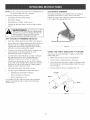
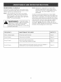
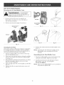
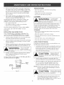
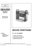
1
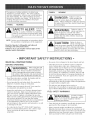
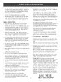
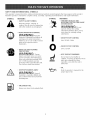
Operator's
Manuam
2-Cycme
GAS TRIMMER
Mode[ No. 316.791880
with
• SAFETY
• ASSEMBLY
• OPERATION
o MAINTENANCE
• PARTS LIST
CAUTION:
Before using
this product,
read this
manual and follow a[[
safety rules and operating
instructions.
Sears, Roebuck
and Co., Hoffman
Visit our website:
Estates,
www.sears.com/craftsman
769-01696
[L 60179, U.S.A.
Warranty
Page
2
Spedfications
Page
17
Safety Rules
Pages
3 -6
Parts List
Pages
18 - 19
Assembly
Page
7
Notes (Intentionally Blank)
Pages
20 - 21
Oil and Fuel Information
Page
8
CARB/
Page
22
Starting/Stopping
Page
9
Operation
Pages
10- 11
Repair Protection Agreement
Service Numbers
Maintenance and Repair
Pages
12 - 15
Troubleshooting
Page
16
TWO
YEAR
Instructions
LiMiTED
WARRANTY
ON CRAFTSMAN
EPA Warranty Information
Page
23
Back Cover
GAS TRIMMER
For two years from the date of purchase, when this Trimmer is used and maintained according
operator's manuaU, Sears wiUUrepair any defect in materiaU or workmanship
free of charge.
This warranty excludes cutting Uine, spark phg and air fluter, which are expendabUe
wear out from normaU use in Uessthan two years.
If this Gas Trimmer is used for commercial
the date of purchase.
or rental purposes,
WARRANTY
SERVICE iS AVAILABLE
BY RETURNING
SEARS STORE OR SEARS PARTS & REPAIR CENTER
This warranty gives you specific
state to state.
Sears, Roebuck
CALiFORNiA
THE
ENGINE
PRODUCT
KNOWN
EXHAUST
CONTAINS
TO THE
STATE
THiS TRIMMER
iN THE UNITED
applies
parts that can
for 30 days from
TO THE NEAREST
STATES.
legal rights, and you many also have other rights which vary from
and Co., Dept. 817 WA, Hoffman
PROPOSiTiON
this warranty
to the
65 WARNING
FROM
THiS
CHEMICALS
OF CALiFORNiA
TO CAUSE CANCER,
BIRTH
OR OTHER
REPRODUCTIVE
DEFECTS
HARM.
Estates,
IL 60179
SPARK
ARRESTOR
NOTE
NOTE: For users on U.S. Forest Land and in the
states of California, Maine, Oregon and Washington.
All U.S. Forest Land and the state of California (Public
Resources
Codes 4442 and 4443), Oregon and
Washington
require,
by law that certain
internal
combustion engines operated on forest brush and/or
grass-covered areas be equipped with a spark arrestor,
maintained in effective working order, or the engine be
constructed, equipped and maintained for the prevention
of fire. Check with your state or local authorities for
regulations pertaining to these requirements. Failure to
follow these requirements could subject you to liability or
a fine. This unit is factory
equipped
with a spark
arrestor. If it requires replacement, ask a Sears or other
qualified service dealer to install the Accessory
Part
#753-04689 Spark Arrestor Kit.
Thepurposeof safetysymbolsis toattractyour
attentionto possibledangers.Thesafetysymbols,
andtheirexplanations,
deserveyourcarefulattention
andunderstanding.
Thesafetywarningsdo notby
themselves
eliminate
anydanger.Theinstructions
or
warningstheygivearenot substitutes
for proper
accidentprevention
measures.
SYMBOL
MEANING
SAFETY ALERT: indicates
danger,
warning or caution. Attention is required in
order to avoid serious personal injury. May
be used in conjunction with other symbols
or pbtographs.
NOTE: Advises you of information or instructions vital to
the operation or maintenance of the equipment.
Read the Operator's Manual(s} and follow all
warnings and safety instructions.
Failure to do so can result in serious injury to the
operator and/or bystanders.
SYMBOL
MEANING
DANGER:
Failure to obey a
safety warning will
result in serious injury to yourself or to
others. Always follow the safety precautions
to reduce the risk of fire, electric shock and
personal injury,
WARNING:
Fa,ure
to obey a
safetywarning can
resultininjury
to yourselfand others,
Always followthe safetyprecautionsto
reduce the riskof fire,
electric
shock and
personal injury.
, Failure to obey a
• safety warning may
result in property damage or personal injury
to yourself or to others. Always follow the
safety precautions to reduce the risk of fire,
electric shock and personal injury.
, IMPORTANT SAFETY INSTRUCTIONS,
READ ALL INSTRUCTIONS
Be aware of risk of injury to the head, hands and feet.
BEFORE
Clear the area to be cut before each use. Remove
rocks, broken glass, nails, wire, string and other
objects which may be thrown or become entangled in
the cutting attachment. Clear the area of children,
bystanders and pets; keep them outside a 50-foot
(15 m.) radius, at a minimum. Even then, they are still
at risk from thrown objects. Encourage bystanders to
wear eye protection. If you are approached, stop the
unit immediately.
OPERATmNG
WARNING:
When using the unit,
you must follow the
safety rubs. Please read these instructions
Please keep these instructions for later use.
• Read the instructions carefully. Be familiar with the
controls and proper use of the unit.
Do not operate this unit when tired, ill or under the
influence of alcohol, drugs or medication.
• Children must not operate the unit. Teens must be
accompanied and guided by an adult.
Inspect the unit before use. Replace damaged parts.
Check for fuel leaks. Make sure all fasteners are in
place and secure. Replace cutting attachment parts
that are cracked, chipped or damaged in any way.
Make sure the cutting attachment is properly installed
and securely fastened. Be sure that the cutting
attachment shield is properly attached, and positioned
as recommended. Failure to do so can result in
personal injury to the operator and bystanders, as well
as damage to the unit.
• Use only Hassle Free lIFM XTRA QUIET Spiral Line.
Never use metal-reinforced line, wire, chain or rope.
These can break off and become dangerous
projectiles.
Squeeze the throttle control and check that it returns
automatically to the idle position. Make all adjustments
or repairs before using the unit.
This unit was not designed to be used as a
brushcutter. Do not attach or operate this unit with any
type of brushcutting blade or brushcutting attachment.
FUEL SAFETY
WARNmNGS
WARNING:
Gaso,ne s
highly
flammable, and its
vapors can explode if ignited. Take the
following precautions:
• Store fuel only in containers specificaiiy designed and
approved for the storage of such materials.
Always stop the engine and allow it to cool before
filling the fuel tank. Never remove the fuel tank cap or
add fuei when the engine is hot. Never operate the unit
without the fuel cap securely in place. Loosen the fuel
tank cap siowiy to relieve any pressure in the tank.
• Mix and add fuel in a dean, well-ventilated outdoor
area where there are no sparks or flames. Remove the
fuel cap slowly, and only after the engine stops. Do
not smoke while fueling or mixing fuel. Wipe up any
spilled fuel from the unit immediately.
Avoid creating a source of ignition for spilled fuel. Do
not start the engine until fuel vapors dissipate.
Move the unit at least 30 feet (9.1 m) from the fueling
source and site before starting the engine. Do not
smoke. Keep sparks and open flames away from the
area while adding fuel or operating the unit.
WHmLE OPERATmNG
• Never start or run the unit inside a dosed room or
building. Breathing exhaust fumes can be fatal.
Operate this unit only in a well-ventilated outdoor area.
Wear safety glasses or goggles that meet ANSI Z87.1
standards and are marked as such. Wear ear/hearing
protection when operating this unit. Wear a face or
dust mask if the operation is dusty.
• Wear heavy long pants, boots, gloves and a long
sleeve shirt. Do not wear loose clothing, jewelry, short
pants, sandals or go barefoot. Secure hair above
shoulder level.
The cutting attachment shield must always be in place
while operating the unit. Do not operate unit without
both trimming lines extended, and the proper line
installed. Do not extend the trimming line beyond the
length of the shield.
• This unit has a dutch. The cutting attachment remains
stationary when the engine is idling. If it does not, take
the unit to a Sears or other qualified service dealer for
an adjustment.
• Adjust the D-handle to your size in order to provide the
best grip.
• Be sure the cutting attachment is not in contact with
anything before starting the unit.
Do not operate the engine faster than the speed
needed to cut, trim or edge. Do not run the engine at
high speed when not cutting.
Always stop the engine when cutting is delayed or
when walking from one cutting location to another.
If you strike or become entangled with a foreign
object, stop the engine immediately and check for
damage. Do not operate before repairing damage. Do
not operate the unit with loose or damaged parts.
Turn the engine to off and disconnect the spark plug
for maintenance or repair.
Use only replacement parts or accessories
recommended for this tool that are sold by Sears or a
Craftsman outlet. Use of any replacement parts or
accessories purchased elsewhere may be hazardous,
and will also void your warranty.
Keep unit clean of vegetation and other materials.
They may become lodged between the cutting
attachment and shield.
To reduce fire hazard, replace a faulty muffler and
spark arrestor. Keep the engine and muffler free from
grass, leaves, excessive grease or carbon build up.
OTHER SAFETY
WARNINGS
Never store the unit, with fuel in the tank, inside a
building where fumes may reach an open flame (pilot
lights, etc.) or sparks (switches, electrical motors,
etc.).
• Allow the engine to cool before storing or transporting.
Be sure to secure the unit while transporting.
Store the unit in a dry place, secured or at a height to
prevent unauthorized use or damage Keep out of the
reach of children.
Never douse or squirt the unit with water or any other
liquid. Keep handles dry, clean and free from debris.
Clean after each use, see Cleaning and Storage
instructions.
• Use the unit only in daylight or good artificial light.
• Avoid accidental starting. Be in the starting position
whenever pulling the starter rope. The operator and
unit must be in a stable position while starting. Refer
to Starting/Stopping Instructions.
• Use the right tool. Only use this tool for its intended
purpose.
• Do not overreach or use on unstable surfaces such as
ladders, trees, steep slopes, rooftops, etc. Always
keep proper footing and balance.
• Always hold the unit with both hands when operating.
Keep a firm grip on both handles or grips.
Keep hands, face, and feet away from all moving
parts. Do not touch or try to stop the cutting
attachment when it rotates.
• Keep outside surface free from oil and fuel.
Do not touch the engine, gear housing or muffler.
These parts get extremely hot from operation, even
after the unit is turned off.
• Keep these instructions. Refer to them often and use
them to instruct other users. If you loan this unit to
others, also loan them these instructions.
SPECIAL NOTE: Exposure to vibrations through
prolonged use of gasoline- powered hand tools could
cause blood vessel or nerve damage in the fingers,
hands, andjoints of people prone to circulation
disorders or abnormal swelling. Prolonged use in cold
weather has been linked to blood vessel damage in
otherwise healthy people. If symptoms occur such as
numbness, pain, loss of strength, change in skin color
or texture, or loss of feeling in the fingers, hands or
joints, discontinue use of this tool and seek medical
attention. A reduced vibration system does not
guarantee avoidance of these problems. Users who
operate power tools on a regular basis must closely
monitor their physical condition and the condition of
this tool.
SAVE THESE
SAFETY
AND
_NTERNAT_ONAL
SYMBOLS
This operator's manuaH describes safety and internationaH symboHs and pictographs that may appear on this product.
Read the operator's manuaH for compHete safety, assembHy, operating and maintenance and repair information,
SYMBOL
MEANING
SYMBOL
THROWN OBJECTS AND
ROTATING CUTTER CAN CAUSE
SEVERE INJURY
Indicates danger, warning, or
_ caution,
SAFETY May
ALERT
SYMBOL
be used
in conjunction
with other symboHs or pictographs,
READ OPERATOR'S
MEANLNG
•
WARNmNG:
Donot
operate without the cutting
attachment shieHd in pHace, Keep
away from the rotating cutting
attachment.
MANUAL
I
Operator's ManuaH(s)and foHHowaHH
warnings
and safety instructions,
WARNiNG:Read
the
FaiHureto do so can resuHt in serious
injury to the operator and/or
ON/OFF STOP CONTROL
ON / START / RUN
ON/OFF STOP CONTROL
bystanders,
WEAR EYE AND HEARING
PROTECTION
0
OFF or STOP
WARNmNG: Thrown
HOT SURFACE WARNING
objects and Houd noise can cause
severe eye injury and hearing Hoss.
Wear eye protection meeting ANSI
Z87.1-1989 standards and ear
protection when operating this unit,
Use a full face shield when needed,
Do not touch a hot muffler or
cyHinder, You may get burned, These
parts get extremeHy hot from
operation, even after the unit is
turned off,
o OIL
KEEP BYSTANDERS AWAY
WARNmNG: KeepaUU
bystanders,
especiaHHy
chiHdren
and
pets, at Heast50 feet (15 m,) from the
operating area,
UNLEADED
FUEL
AHwaysuse dean, fresh unHeadedfuel
Refer to operator's
proper type of oil
manuaH for the
APPUCAT_ONS
Cutting
grass and Hight weeds
Edging
• Decorative
J
trimming
around
trees, fences,
etc.
Fuel Cap
Starter Rope
Grip
On/Off
Stop
Control
\
Shaft Grip
/
Throttme
Control
"\
\
Throttle
Twist and
Edge TM
Control
Red EZ:
Fire TM Lever
Shaft
Housing
Primer Bumb
Muffler
Spark Pmug
Air Filter/Mumer
Cover
Line Cutting
Blade
Cutting
Attachment
Shie_d_
Cutting
Attachment
INSTALL
(nsta((
AND ADJUST
THE D-HANDLE
1. Mace the D-handHe down on to the shaft housing and
the bottom champ so that the handHe sHants towards
the shaft gdp (Fig. 1). Mace handHeand champ a
minimum of 6 inches from the end of the shaft grip.
2.
Start screws with a HargeHat-head or T-25 Torx
screwdriver. Do not tighten untiHyou make the handHe
Shaft
Grip
/
On/Off
Stop Control
Minimum 6 inches
Bottom
Clamp
F_g. 1
Adjust
3. WhiHe hoHding the unit in the operating position
(Fig. 2), position the D-handHe to the Hocation that
provides you the best grip.
4. Tighten the champ screws evenHy untiHthe D-handHe is
secure.
F_g. 2
OraLAND
FUEL
MmXH_G
H_STRUCTmONS
Old and/or improperly raked fuel are the main reasons
for the unit not running properly. Be sure to use fresh
(less than 60 days old), clean unleaded fuel. Follow the
instructions carefully for the proper fuel/oil mixture.
Definition
of Blended
Fuels
Today's fuels are often a blend of gaso%e and
oxygenates such as ethanol, methanol, or MTBE (ether).
Alcohol-blended fuel absorbs water. As little as 1%
water in the fuel can make fuel and oil separate and
leads to formation of adds during storage. When using
alcohol-blended fuel, use fresh fuel.
To Obtain
Correct
Fuel Mix:
Thoroughly mix the proper ratio of 2-cycle engine oil
with unleaded gasoline in a separate fuel can. Use a 40:1
fuel/oil ratio. Do not mix them directly in the engine fuel
tank. See the Fuel Mixture Table for specific gas and oil
mixing ratios.
NOTE: One gallon (3.8 liters) of unleaded gasoline mixed
with one 3.2 oz. (95 ml.) bottle of
2-cycle oil makes a 40:1 fuel/oil ratio.
FUEL MIXTURE
Using Blended Fuels
if you choose to use a blended fuel or its use is
unavoidable, follow recommended precautions:
TABLE
+
• AHways use the fresh rue[ mix explained in your
operator's manual
• Always shake the fuel mix before fueling the unit
• Drain the tank and run the engine dry before storing
the unit
UNLEADED
GAS
1 GALLON US
(&8 LITERS)
2 CYCLE OIL
32 FL OZ.
msram)
Using Fuel Additives
The bottle of 2-cycle oil that came with your unit
contains a fuel additive which will help inhibit corrosion
and minimize the formation of gum deposits, it is
recommended that you always use Craftsman 2-cycle oil
with this unit.
if Craftsman 2-cycle oil is unavailable, use a good 2cycle oil designed for air-cooled engines along with a
fuel additive, such as STA-B[L" Gas Stabilizer or an
equivalent. Add 0.8 oz. (23 ml.) of fuel additive per gallon
of fuel according to the instructions on the container.
NEVER add fuel additives directly to the unit's fuel tanL
, For proper engine
• operation and
maximum re[lability, pay strict attention to
the oil and fuel mixing instructions on the
2-cycle oil container. Using improperly mixed
rue[ can severeJy damage the engine.
25 mm
1 LITER
MIXING RATIO - 40:1
WARNING:
Gasoline
is
extremely
flammable. Ignited vapors may explode.
Always stop the engine and allow it to cool
the fuel tank. Do not smoke
while filling the tank. Keep sparks and open
flames at a distance from the area.
WARNING:
Remove fue, cap
slowly to avoid injury
from fuel spray. Never operate the unit
without the fuel cap securely in place.
WARNING:
Add fue, in a c,ean,
well-ventilated
outdoor area, Wipe up any spilled fuel
immediately,
Avoid creating a source of
ignition for spilled fuel, Do not start the
engine
until fuel vapors dissipate,
NOTE: Dispose of the old fuel/oil mix in accordance to
Federal, State and Local regulations.
WARNING:
Operate this unit onIy in a
weII-ventiIated outdoor area.
Carbon monoxide exhaust fumes can be lethal in a
confined area.
_ Stop/Off
Start/On,
(O)
WARNING;
Avoid acddental starting,
Make sure you are in the
starting position when pulling the starter rope (Fig. 5).
To avoid serious injury, the operator and unit must be
in a stable position while starting.
Throttle
Control
F_g.3
STARTING
1.
iNSTRUCTiONS
Mix gas with oil. Fill fuel tank with fuel/oil mixture.
See Oil and Fuel Mixing Instructions.
Primer
Bulb
2_ Make sure the On/Off Stop Contro] is in the ON [m]
position (Fig. 3).
,_ ,, ,,i@,_ 3.
Fully press and release the primer bulb 10 times,
slowly. Some amount of fuel should be visible in the
primer bulb and fuel lines (Fig. 4). [f you can't see
fuel in the bulb, press and release the bulb as many
times as it takes before you can see fuel in it.
Push the red EZ-Fire TM Lever towards the primer
bulb until it clicks and locks into place (Fig. 4).
NOTE: The unit uses the Jncredi-Pull TM starting system
with MAX FiRE iGNiTiON TM , which significandy
reduces the effort required to start the engine. You
must pull the starter rope out far enough to hear
the engine attempt to start. There is no need to
pull the rope briskly-- there is no harsh resistance
when pulling. Be aware that this starting method is
vastly different from (and much easier than) what
you may be used to.
Red EZ:Fire
Lever
Fig. 4
Starting
with a controlled and steady motion up to 10
times, until the engine starts.
6.
When the engine starts, squeeze the throttle control
for 15 to 30 seconds. This will warm up the unit. The
red EZ-Fire TM lever will click off automatically when
you squeeze the throttle control.
\lnered,-Pu,!
JFoooThe engine does not start, go back to step 3.
......................
JFoooTheengine stops while you are squeezing the
throttle, go back to step 4.
JFoooThe engine stops before you squeeze the throttle
control, hold the throttle control and pull the starter
rope until the trimmer starts.
NOTE: If you are having trouble starting the unit or are
operating in extreme temperatures (below 40° F,
above 90° F), refer to the Troubleshooting section.
Handle
Fig. 5
STOPPING
iNSTRUCTiONS
1. Release your finger from the throttle control. Allow the engine
to cool down by idling.
2.
Put the On/Off Stop Control in the OFF (O) position (Fig. 3).
Position
TM
HOLDING
THE TRmMMER
NOTE: Before inserting new line into the holes in the
cutting head, identify the proper holes. Follow
directions as shown on the line glide plate. Do Not
attempt to remove the cutting head from the unit
when replacing line.
WARNmNG:
Always wear eye,
hearing,
footand
body protection
to reduce theriskofinjury
when operating this unit.
Before operating the unit, stand in the operating position
(Fig. 6). Check for the following:
The operator is wearing eye protection and proper
dotMng
•
With a siighdy-bent right arm, the operator's
hoiding the shaft grip
•
The operator's Heftarm is siightiy bent, the Hefthand
hoiding the D-handb
The unit is at waist bvei
•
1.
Remove the old line and line glide plate from the
cutting head.
2.
Clean entire surface of cutting head.
3.
Reinstall line glide plate (Fig. 7). Align arrow with:
A- when using medium (red) or large (black) line
hand is
B- when using lines with diameters smaller than
medium (red)line
Line Glide
Plate
The cutting attachment is paraHei to the ground and
easiiy contacts the grass without the need to bend over
Cutting
Head
F_g. 7
NOTE: Line glide plate must be reinstalled in cutting
head before inserting new line.
4.
Insert both ends of your line through the proper holes
in the side of the cutting head (Fig. 8).
Positioning
Tunnel
\
F_g. 6
F_g. 8
UNE REPLACEMENT
5.
for Hassle-Free III TMCutting Head
Always use Craftsman Hassb-Free IIFM XTRA QUIET
Spiral Line.
Choose the line size best suited for thejob at hand. Red
colored line is designed for cutting grass and small
weeds. Black colored line is designed for cutting larger
weeds and light brush.
Pull the line and make sure the line is against the hub
and is fully extended through the positioning tunnels
(Fig, 9).
Line against
the hub
Positioning
F_g.9
6.
10
Correctly installed line will be the same length on
both sides.
DECORATIVE
NOTE: Do not rest the HassHe-Free IWM Cutting Head on
the ground whiHe the unit is running.
Decorative trimming is accomplished by removing all
vegetation around trees, posts, fences and more,
Rotate the whole unit so that the cutting attachment is at
a 30" angle to the ground (Fig, 10),
Some Hinebreakage will occur from:
•
TR_MM_NG
EntangHement with foreign matter
Attempting to cut thick, staHkyweeds
Forcing the Hineinto objects such as walls or fence
posts
WARN
mNG: the
Donotremove
oraUter
Hinecutting Made
assemMy. Excessive HineHength will make the
dutch overheat. This may Headto serious
personal injury or damage to the unit.
TraPS FOR BEST TRmMMmNG RESULTS
•
Keep the cutting attachment
paraHeHto the ground.
•
Do not force the cutting attachment. AHow the tip of
the Hineto do the cutting, especially along walls.
Cutting with more than the tip will reduce cutting
efficiency and may overload the engine.
•
Cut grass over 8 inches (200 mm) by working from
top to bottom in small increments to avoid
premature line wear or engine drag.
•
Cut from left to right whenever possible, Cutting to
the right improves the unit's cutting efficiency,
Clippings are thrown away from the operator,
•
Slowly move the trimmer in and out of the cutting
area at the desired height. Move either in a forwardbackward or side-to-side motion. Cutting shorter
lengths produces the best results.
•
Trim only when grass and weeds are dry,
•
The life of your cutting line is dependent upon:
•
Following the trimming techniques
•
What vegetation is being cut
•
Where vegetation is cut
Fig. 10
USING THE TWIST AND EDGE TM FEATURE
You can use the Twist and
unit to edge grass:
1,
Edge
TM
coupler to convert the
Make sure the unit is turned completely off,
2, Turn the knob counterclockwise
3,
to loosen,
Grasp the boom below the coupler and firmly twist it
90 " in either direction (depending on which way you
want to edge).
4, Turn the knob clockwise to tighten (Fig. 11),
Coupler
Boom
For example, the line will wear faster when trimming
against a foundation wall as opposed to trimming
around a tree,
Knob
Fig. 11
11
MAINTENANCE
SCHEDULE
NOTE: Maintenance, repHacement, or repair of the
emission controH devices and system may be
Perform these required maintenance procedures at the
frequency stated in the tame. These procedures shouHd
also be a part of any seasonaHtune-up.
information,
NOTE: Some maintenance procedures may require
special tooHsor sMHs, If you are unsure about
these procedures, take your unit to a Sears or
other qualified service dealer. Call 1-800-4-MYHOME te for more information,
In order to assure peak performance of your engine,
inspection of the engine exhaust port may be necessary
after 50 hours of operation, If you notice lost RPM, poor
performance or general lack of acceleration, this service
may be required, If you feel your engine is in need of this
inspection, refer service to a Sears or other qualified
service dealer, Call 1-800-4-MY-HOME <_)for more
WARNING:
To prevent serious
inJury, never perform
maintenance or repairs with unit running,
AHways service and repair a cooH unit,
Disconnect the spark pHugwire to ensure that
the unit cannot start,
information, DO NOT attempt to perform this process
yourself as engine damage may result from contaminants
involved in the cleaning process for the port.
FREQUENCY
MAINTENANCE
REQUIRED
Before starting engine
Fill fuel tank with fresh fuel
Page 8
Every 10 hours
Clean and re-oil air filter
Page 13
Every 25 hours
Check and clean spark arrestor
Check spark plug condition and gap
Page 14
Page 15
Every 50 hours
Inspect exhaust port and spark arrestor screen for clogging or
obstruction to assure maximum performance levels
Page 14
12
REFER TO
AmR FmLTER MAmNTENANCE
Removing
the Air FiBter/Muffler
Cover
JNG"• To
avoid serious
personaU injury,
aUways turn your unit off and allow it to cooU
before you dean or service it.
Remove the four (4) screws securing the air
fiHter/muffler cover (Fig. 12). Use a flat Made or
T20 Torx bit screwdriver.
2.
Air Filter
Pull the cover from the engine. Do not force.
Red EZ-Fire
Inside Muffler
Cover
Fig. 13
TM
Fig. 14
Screws
/
Fig. 15
/
Fig. 16
Fig. 12
6.
Cleaning the Air Filter
CHeanand re-oiH the air fiHterevery 10 hours of operation.
It is an important item to maintain. FaiHureto maintain
your air filter properly can result in poor performance or
can cause permanent damage to your engine.
Replace the air filter inside the air filter/muffler cover
(Fig. 13).
NOTE: Operating the unit without the air filter and air
filter/muffler cover assembly will VOID the
warranty.
1. Remove air filter/muffler cover. Refer to Removing
the Air Filter/Muffler Cover.
2. Turn cover over and look inside to locate the air filter.
Remove the air filter from inside the air filter/muffler
cover (Fig. 13).
3. Wash the filter in detergent and water (Fig. 14). Rinse
the filter thoroughly. Squeeze out excess water.
Allow it to dry completely.
4. Apply enough clean SAE 30 oil to lightly coat the filter
(Fig. 15).
5. Squeeze the filter to spread and remove excess oil
(Fig. 16).
Reinstalling
the Air Filter/Muffler
Cover
1.
Place the air filter/muffler cover over the back of the
carburetor and muffler. Align the screw holes.
2.
Insert the four (4) screws into the holes in the air
filter/muffler cover (Fig. 12) and tighten.
Do not over tighten.
NOTE: Make sure the red EZWire TM Lever is positioned
away from the primer bulb.
13
SPARK ARRESTOR
NOTE:
MAINTENANCE
Mease Hetengine cooLThe exhaust can onHy flow
in one direction: AWAY from the engine. Pay
chose attention when disassemMing the muffler
so you can put it back together correctHy. FaiHure
to do so will damage the unit and may cause
serious personaH injury.
8.
Replace the two screws you removed in Step 2 and
tighten them securely.
9.
Reinstall the air filter/muffler cover (Fig. 12).
WARNING:
Remove air filter/muffler cover. Refer to Removing
the Air Filter/Muffler Cover,
2.
3.
5.
Reinstall the spark arrestor screen by putting the
"raised" portion of the screen inside the recessed
hole of the muffler. Make sure that the spark arrestor
screen fits flat against the muffler.
6.
Place the spark arrestor plate on top of the spark
arrestor screen with the raised side up and the
opening facing toward the engine (Fig. 17)
NOTE: Careless adjustments can seriously damage your
unit. Contact a Sears or other qualified service dealer to
make carburetor adjustments. Call 1-800-4-MY-HOME <m
for more information.
Check
The condition of the air filter is important to the operation
of the unit. A dirty air filter will restrict air flow and
change the air/fuel mixture. This is often mistaken for an
out of adjustment carburetor. Check the condition of the
air filter before adjusting the idle speed screw. Refer to
Air Filter Maintenance.
Adjust
_die Speed
Screw
If, after checking the fuel mixture and cleaning the air
filter, the engine still will not idle, adjust the idle speed
screw as follows:
1. Start the engine and let it run at a high idle for a
minute to warm up. Refer to Starting/Stopping
Instructions.
Muffler
WARNING:
The cutting
attachmentmay spin
duringidlespeed adjustments,Wear
protectiveclothingand observe allsafety
instructions
to preventseriouspersonalinjury,
Spark Arrestor
Screen
Spark
"\
Recessed
Fuel Mixture
Old and/or improperly mixed fuel is usually the reason
for improper unit performance. Drain and refill the tank
with fresh, properly-mixed fuel prior to making any
adjustments. Refer to Off and Fuel Information.
Clean Air Filter
Place the spark arrestor hood on top of the spark
arrestor plate with the "raised" side up and the
opening facing AWAY from the engine (Fig. 17). Verify
that the exhaust will be directed AWAY from the
engine.
Engine
ADJUSTMENT
The idle speed of the engine is adjustable through the air
filter/muffler cover (Fig. 18).
Using a small flat Made screwdriver, carefully pry up
the spark arrestor screen from the recessed hoD,
taking care to notice that the "raised" part of the
spark arrestor screen is inside the recessed hoHe.
Remove the spark arrestor screen from the muffHer.
CHeanthe spark arrestor screen with a wire brush.
Replace it if it is damaged, or if you are unable to
clean it thoroughly.
7.
CARBURETOR
Locate the muffHer, but do not remove it. Find the two
(2) screws on the bottom of the muffHer (Fig. 17).
These two screws hoHdthe Spark Arrestor Hood
AssemMy and the spark arrestor screen to the
bottom of the muffHer. Remove the two (2) screws
using either a Torx T20 or fiat Made screwdriver.
4.
/
HoJe
Plate
Arrestor
Idle Speed Screw
Spark
Arrestor
Hood
\
Spark Arrestor
Hood
Assembmy Includes:
Spark Arrestor Screen
Spark Arrestor Plate
Spark Arrestor Hood
and Screws
Opening
Screws
Fig. 17
iftheexhaust
deflector assembly is
not tightened securely, it could fall off causing
damage to the unit and possible serious
personal injury,
14
Fig. 18
2.
TRANSPORTING
ReHeasethe throttHe trigger and Herthe engine idHe.If
the engine stops, insert a small phillips or flat Made
screwdriver into the hod in the air fiHterimuffler cover
(Fig. 18). Turn the idHespeed screw in, clockwise,
1/8 of a turn at a time (as needed) unti[ the engine
idHes smootMy.
Allow the engine to cool before transporting.
Drain fuel from unit.
• Tighten fuel cap before transporting.
Secure the unit while transporting.
3.
If the engine appears to be idHingtoo fast, turn the
idHespeed screw counterclockwise
1/8 of a turn at
a time (as needed), to reduce idHespeed.
Checking the fue[ mixture, cHeaning the air fiHter, and
adjusting the idHespeed shouHd soHvemost engine
proMems. If not and all of the following are true:
• the engine will not idle
• the engine hesitates or stalls on acceleration
• there is a loss of engine power
CLEANING
WARNING:
alwaysturnyourtrimmeroffand allowittocool
beforeyou cleanor maintainit.
Use a small brush to dean off the outside of the unit.
Do not use strong detergents. Household cleaners that
contain aromatic oils such as pine and lemon, and
solvents such as kerosene, can damage plastic housing
or handle. Wipe off any moisture with a soft cloth.
Have the carburetor adjusted by a Sears or other qualified
service dealer. Call 1-800-4-MY-HOME @for more
information..
REPLACING
THE SPARK
STORAGE
• Never store a fueled unit where fumes may reach an
open flame or spark.
PLUG
Use a Champion RDJ7Y spark plug, or equivalent. The
correct air gap is 0.020 inch (0.5 ram}. Remove the plug
after every 25 hours of operation and check its condition.
• Allow the engine to cool before storing.
• Store the unit locked up to prevent unauthorized use
or damage.
1. Stop the engine and allow it to cool. Grasp the plug
wire firmly and pull it from the spark plug.
2.
3.
• Store the unit in a dry, weDventilated area.
• Store the unit out of the reach of children.
Clean around the spark plug. Remove the spark plug
from the cylinder head by turning a 5/8-inch socket
counterclockwise.
LONG
STORAGE
1. Carefully drain the fuel tank by running the unit dry or
remove fuel cap and tip the motor housing over and
drain oiFgas fuel into a container with the same 2cycle fuel mixture. Do not use fuel that has been
stored for more than 60 days+
WARNING:
4.
TERM
If you plan on storing the unit for an extended time, use
the following storage procedure:
Replace a cracked, fouled or dirty spark plug. Set the air
gap at 0.020 in. (0.5 mm} using a feeler gauge (Fig+19)+
electrodes.
the cylinder.
To
avo+d
ser+ous
personalinjury,
Do not sand blast,
scrape or clean
Grit in the engine could damage
Install a correctly-gapped spark plug in the cylinder
head. Tighten by turning the 5/8-inch socket
clockwise until snug.
CAUTION"
accordance
regulations.
If using a torque wrench torque to 110-120 in.+ib. (12.313.5 N+m}o Do not over tighten.
Disposemixture
of the old
•
fuel/oil
in
with all Federal, State, and Local
2. Start the engine and allow it to run until it stalls. This
ensures that all fuel has been drained from the carburetor.
3. Allow the engine to coo[. Remove the spark plug and
put 1 oz. (30 ml) of any high quality motor oil or
2-cycle oil into the cylinder. Pull the starter rope
slowly to distribute the oil. Reinstall the spark plug.
Spark
Plug
0.020 in.
(0.5 mm}
NOTE: Remove the spark plug and drain all of the oil
from the cylinder before attempting to start the
trimmer after storage.
+
t
.
Dispose of the old oil
•
in accordance with a[[
Federal State, and Local regulations.
Fig. 19
4.
15
ThorougHy dean the unit and inspect it for any
loose or damaged parts. Repair or replace
damaged parts and tighten loose screws, nuts or
bolts. The unit is ready for storage.
CAUSE
ACTION
1. Empty fueHtank
I.Fill
fueltankwithproperlymixed fuel
2. Primer buHbwasn't pressed enough
2. Press primer bulb fully and slowly 10 times
3. Engine is flooded
3. Squeeze the trigger and pull the starter rope
4. OHdor improperly mixed fueH
4. Drain gas tank and add fresh fuel mixture
5, FouHed spark pHug
5. Replace or clean the spark plug
6. Mugged spark arrestor
6. Clean or replace spark arrestor
7. Red EZ-Fke TM Heverwasn't flipped/set
7. Move lever to the starting position
8, The outside temperature
is bellow 40 ° F
8. Pull the starter rope up to 10-15 times
9. The outside temperature
is above 90 ° F
9. Squeeze the throttle control and pull the starter rope
without moving the Red EZ-Fire
CAUSE
TM
lever
ACTION
1. Air fiHteris pHugged
1. Replace or clean the air filter
2. OM or improperly mixed fueH
2. Drain gas tank and add fresh fuel mixture
3. Improper carburetor adjustment
3. Adjust according to the Carburetor Adjustments
CAUSE
ACTION
I.OHd or improperlymixed fueH
1, Drain gas tank and add fresh fuel mixture
2. Improper carburetor adjustment
2. Take to a Sears or other qualified service dealer for
3. Cutting attachment
3. Stop the engine and clean the cutting attachment
bound with grass
4. Dirty air fiHter
4. Clean or replace the air filter
5. Mugged spark arrestor
5. Clean or replace spark arrestor
CAUSE
ACTION
I.OHd or improperlymixed fueH
1. Drain gas tank and add fresh fuel mixture
2.AirfiHter
ispHugged
2. Replace or clean air filter
3. Improper carburetor adjustment
3. Take to a Sears or other qualified service dealer for
an adjustment
4. FouHed spark pHug
4. Replace or clean the spark plug
5. Mugged spark arrestor
5. Clean or replace spark arrestor
NOTE:
For repairs
Repair
beyond
center
the minor
adjustments
listed above, contact
your nearest Sears Parts
®
(1 800 4 M%HOME
) or other qualified
service dealer for an adjustment.
16
&
EngineType .................................................................................................
Air-Cooled,
2-Cycle
Displacement .........................................................................................................................................
31.5 cc (1.95 cu in.)
Idle Speed RPM ......................................................................................................................................
2,800 - 3,600 rpm
Operating RPM ..................................................................................................................................................
7,200+ rpm
Ignition Type ....................................................................................................................
Electronic-MAX FBREIGNITION TM
Ignition Switch ..............................................................................................................................................
Rocker Switch
Spark Hug Gap .......................................................................................................................................
0.020 in. (0.5 mm)
Lubrication ...................................................................................................................................................
Fuel/Oil Mixture
FueFOil Ratio ..................................................................................................................................................................
40:1
Carburetor .......................................................................................................................................
Diaphragm, AN-Position
Starter ...........................................................................................................................
Incredi-PuN TM Starting Auto Rewind
Muffler .....................................................................................................................................................
Baffled with Guard
Throttle ...............................................................................................................................................
Fuel Tank Capacity .......................................................................................................................................
Manual Spring Return
13 oz. (384 ml)
Drive Shaft Housing .............................................................................................................
Steel Tube (Twist and Edge TM)
Throttle Control ........................................................................................................................................
Finger-Tip Trigger
Approximate Unit Weight (No fuel, with cutting attachment, shield, edge guide and D-handle) ................... 14 Ibs. (6 kg)
Cutting Mechanism ..........................................................................................................................
Hassle Free IIFM Head
Trimming Line Diameter .....................................................................................
Hassle Free IIITM XTRA QUIET Spiral Line
Cutting Path Diameter ........................................................................................................................
14 inches (35.56 cm)
+All specifications are based on the latest product information available at the time of printing. We reserve the right to
make changes at any time without notice.
17
ENGINE
PARTS - MODEL 791880
2-CYCLE GAS TRIMMER
@
/
@
item
1
2
3
4
5
6
7
8
9
10
11
12
13
14
15
16
17
18
19
20
21
22
23
24
25
26
27
28
29
30
Part No.
753-04810
791-180350B
791-180351
753-04227
753-1194
753-04338
791-610675
791-181860
791-683974B
753-1196
791-684451
753-1208
753-04401
791-612134
753-04606
791-181803
791-181086
791-683398
791-145308
753-04702
791-182736
791-181525
753-04459
753-04286
753-1200
753-04288
753-05011
791-613103
753-04417
753-1202
Description
Air Cleaner Assembly
Air Cleaner Filter
Carburetor Mounting
Choke Extension
Choke Plate
Carburetor Assembly
Carburetor Gasket
Carb Mount Screw
@
Item
31
(includes 2 & 37)
32
33
34
35
36
37
38
39
40
41
42
43
44
45
46
47
48
49
50
51
Screw Assembly
(includes 7 & 18)
Primer and Hose Assembly
Carb Mount Assembly (includes 8, 11 & 12)
Reed Assembly
Carburetor Mount Gasket
Crank Case Service Assembly (includes 8)
Rear Mounting Pad
Fuel Tank Assembly (includes 16-18)
Fuel Cap Assembly
Fuel Return Line
Fuel Line Assembly
Front Mounting Pad
Shroud Extension & Stand (includes 37)
Flywheel Assembly
Spacer
Recoil Pulley Assembly (includes 2(_)
Recoil Spring
Rope Guide
Palnut
Pull Handle
Part No,
753-05049
Description
Starter Housing Assembly
(includes 23-30, 32 & 37)
791-181862
791-182396
791-182369
791-153592
753-04497
791-181345
791-182519
753-04003
791-180217
753-04792
791-611063
753-05012
791-610311B
753-04618
753-04619
753-04620
753-04814
753-04367
753-04182
791-182723
753-04689
753-1209
753-04812
791-181599
Housing Screw
Clutch Washer
Clutch Rotor
Clutch Drum
Clutch Cover
Cover Screw
Anti-Rotation
18
(includes 37-40)
Screw
Clamping Screw
Clamping Nut
Wire Leads and Sleeve
Ground Tab
Module Assembly (includes 42)
Spark Plug
Muffler Assembly (includes 46 & 47)
Exhaust Gasket
Muffler Mounting Bolt Assembly
Cylinder Assembly (includes 50 & 51)
Piston and Rod Assembly
Cylinder Gasket
Cylinder Bolt
Spark Arrestor
Piston Ring Set
Short Block Assembly (includes 13, 44 & 48-51)
Clutch Springs (Qty. 2)
Items Not Shown
Rope
Pressure Plate Assembly (includes 30)
Plate Screw
Assembly
Assembly
Assembly
BOOM
& TRIMMER
?
Item
1
2
3
4
5
6
7
8
9
10
11
12
13
14
15
16
17
18
19
20
21
22
23
24
25
26
Part No,
753-04234
753-04119
791-182690
791-182405
753-04405
791-610327
753-05022
791-180869
791-181070
791-182167
791-182168
753-05029
791-181981
791-182057
791-181617
753-04386
753-05040
753-05044
791-182200
791-182193
791-182195
791-145569
791-682061
753-1158
753-05045
753-05036
Description
Throttle Housing Assembly (includes 2-4)
Throttle Trigger
Throtde Trigger Spring
Switch Assembly
Throttle Cable Assembly
Harness Clip
Upper Drive Shaft Housing
Deluxe D-Handle Assembly (includes 9-11)
Screw
[)-Handle
[)-Handle Base
Twist Boom Coupler (includes 13-16)
Adjustment Knob (includes 16)
Screw
Bolt
Nut
Flexible Drive Shaft
Lower Drive ShaR Housing
Shield Mount Screw Assembly
Gearbox Assembly
Gearbox Screw
Anti-Rotation Screw
Blade Assembly
Shield Assembly (includes 23)
Cutting Head Assembly
Cutting Head Cap
Items Not Shown
19
PARTS - MODEL 791880
2-CYCLE GAS TRIMMER
20
21
California
/ EPA Emission
Your Warranty
Control
Rights
Warranty
Statement
and Obligations
The California Air Resources Board, The Environmental Protection Agency and Sears are pleased to explain the emission
control system warranty on your 2000 and later small off-road engine. New small off-road engines must be designed, built
and equipped to meet stringent anti-smog standards. Sears, Roebuck and Co. must warrant the emission control system
on your small off-road engine for the periods of time listed below provided there has been no abuse, neglect or improper
maintenance of your small off-road engine.
Your Emission control system may include parts such as the carburetor or fueNnjection system, the ignition system, and
catalytic converter. Also included may be hoses, belts, connectors and other emission-related assemblies.
Where a warrantable condition exists, Sears will repair your small off-road engine at no cost to you including diagnosis,
parts and labor.
The 2000 and later small off-road
engines
engine is defective,
the part w+mm
be repaired
are warranted
for two
or replaced
by Sears.
years,
if any
emission-related
part
on your
Owner's Warranty
Responsibilities
° As the small off-road engine owner, you are responsible for the performance of the required maintenance listed in your
operator's manual. Sears recommends that you retain all receipts covering maintenance on your small off-road engine,
but Sears cannot deny warranty solely for the lack of receipts or for your failure to ensure the performance of all
scheduled maintenance.
, As the small off-road engine owner, you should however be aware that Sears may deny you warranty coverage if your
small off-road engine or a part has failed due to abuse, neglect, improper maintenance or unapproved modifications.
You are responsible for presenting your small off-road engine to a Sears authorized service center as soon as problem
exists. The warranty repairs should be completed in a reasonable amount of time, not to exceed 30 days.
If you have any questions regarding your warranty rights and responsibilities,
you should call 1-800-4-MY-HOML
_(_)
.
Manufacturer's
Warranty
Coverage
, The warranty period begins on the date the engine or equipment is delivered to the retail purchaser.
• The manufacturer warrants to the initial owner and each subsequent purchaser, that the engine is free from defects in
material and workmanship which cause the failure of a warranted part for a period of two years.
Repair and replacement of warranted part will be performed at no charge Lo the owner at an authorized Sears service
center. For the nearest location please contact Sears at: 1-800-4-MY-HOME _.
, Any warranted part which is not scheduled for replacement, as required maintenance or which is scheduled only for
regular inspection to the effect of "Repair or Replace as Necessary" is warranted for the period. Any warranted part
which is scheduled for replacement as required maintenance will be warranted for the period of time up to the first
scheduled replacement point for that part.
, The owner will not be charged for diagnostic labor which leads to the determination
the diagnostic work is performed at an authorized Sears Service Center.
• The manufacturer
under warranty.
is liable for damages to other engine components
that a warranted part is defective if
caused by the failure of a warranted
part still
° Failures caused by abuse, neglect or improper maintenance are not covered under warranty.
• The use of add-on or modified parts can be grounds for disallowing a warranty claim. The manufacturer is not liable to
cover failures of warranted parts caused by the use of add-on or modified parts.
, In order to file a claim, go to your nearest authorized Sears Service Center. Warranty service or repairs will be provided
at all authorized Sears Service Centers.
• Any manufacturer approved replacement part may be used in the performance of any warranty' maintenance or repair
of emission related parts and will be provided without charge to the owner. Any replacement part that is equivalent in
performance or durability may be used in non-warranty
maintenance or repair and will not reduce the warranty
obligations of the manufacturer.
• The following components are included in the emission related warranty: engine, air filter, carburetor,
fuel pick up/fuel filter, ignition module, spark plug and muffler.
22
primer, fuel lines,
Repair
Protection
Agreements
Congratulations on making a smart purchase.
Your new Craftsman _ product is designed and
manufactured for years of dependable operation. But like all products, it may require repair
from time to time. That's when having a Repair
Protection Agreement can save you money and
aggravation.
Purchase a Repair Protection Agreement now
and protect yourself from unexpected hassle
and expense.
Here's what's included in the Agreement:
[]
[]
[]
[]
[]
Expert service by our 12,000 professional
repair specialists
Unlimited service and no charge for parts
and labor on all covered repairs
Product replacement if your covered product can't be fixed
Discount of 10% from regular price of
service and service-related parts not covered by the agreement; also, 10% off regular
price of preventive maintenance check
Fast help by phone - phone support from a
Sears technician on products requiring in-home
repair, plus convenient repair scheduling
Once you purchase the Agreement, a simple
phone call is all that it takes for you to schedule
service. You can call anytime day or night, or
schedule a service appointment online.
Sears has over 12,000 professional repair specialists, who have access to over 4.5 million
quality parts and accessories. That's the kind of
professionalism you can count on to help prolong the life of your new purchase for years to
come. Purchase your Repair Protection Agreement today!
Some limitations and exclusions apply.
For prices and additional information call
1-800-827-6655.
Sears
Installation
Service
For Sears professional installation of home
appliances, garage door openers, water heaters,
and other major home items, in the U.S.A. call
1-800-4-MY-HOME®
23
® Registered
® Marca
Trademark
Registrada
/
TM
/
TM
Trademark
/
SM
Marca de Fabrica /
MCMarque de commerce /
MD
Service
SM
Marque d@osee
Mark of Sears,
Marca de Servicio
de Sears,
Roebuck
de Sears,
Roebuck and Co.
and Co.
Roebuck
and Co.
® Sears,
Roebuck
and Co.