1
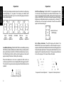
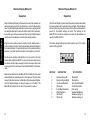
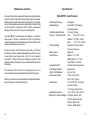
Operator's Manual
Operator's Manual
Machine Control
8261 State Route 235
Dayton, Ohio 45424 USA
Phone: (937) 482-0200
Fax: (937) 482-0030
www.apache-laser.com
BULLSEYE 3 Laser Receiver
Remote Display Model 14
Thank you for purchasing an Apache Technologies, Inc. product. Your
BULLSEYE 3™ receiver is a premium quality tool that has been
designed and manufactured to provide years of precise and reliable
performance. The system has been specifically designed for use in
harsh construction environments.
This manual is an important part of your purchase as it will familiarize
you with the unit and explain the numerous features that have been
designed into it. Please read this manual thoroughly before using your
BULLSEYE 3 receiver.
Please contact your Apache dealer or the Apache factory should you
have questions regarding specific applications or if you require
additional information. Contact information is located on the back
cover. Additional contacts are:
Website:
www.apache-laser.com
Email:
[email protected]
[email protected]
EMC
DECLARATION OF CONFORMITY
Application of Council Directive(s):
89/336/EEC
Manufacturer's Name:
Apache Technologies, Inc.
Manufacturer's Address:
7415 Chambersburg Road
Dayton, OH 45424 USA
Model Number(s):
BULLSEYE 3 systems
and RD14 Remote Display
Equipment Type/Environment:
ITE/Residential, commercial,
light industrial
Standards:
EN55011, 1991
IEC801-2, 1991
IEC801-3, 1984
IEC801-4, 1988
We, the undersigned, hereby declare that the equipment specified
above conforms to the above Directive(s)
Manufacturer
Signature: _______________________________
Name:
Robert G. Conner
_______________________________
Position:
President
_______________________________
Place:
Apache
Technologies, Inc.
_______________________________
Date:
August 20, 2001
_______________________________
Notes:
Contents
BULLSEYE 3 Laser Receiver
System Description..................................................2
Controls and Displays...............................................3
Battery Installation / Charging....................................4
Operation..................................................................6
Installation...............................................................10
Remote Display Model 14
System Description.................................................13
Controls and Displays.............................................13
Operation................................................................14
Maintenance and Care........................................................16
Specifications......................................................................17
Warranty .............................................................................18
P/N ATI-030038 REV B
System Description
The Apache BULLSEYE 3 laser receiver is a rugged, multipurpose,
easy-to-use electronic sensor that detects laser light generated by
rotating laser transmitters. The BULLSEYE 3 is designed to work with
nearly all makes and models of rotating lasers and will detect both
visible and invisible beams. When installed, the operator is given
visual indication of the reference plane of laser light’s position relative
to the cutting edge of the machine. The features and versatility built
into the BULLSEYE 3 provide a product that can be adapted to many
different types of construction and agricultural machinery. The
BULLSEYE 3 will increase utilization and productivity of machinery
saving time, money, and materials.
The operator can customize the settings of the BULLSEYE 3 to meet
the job site requirements. Settings are provided for adjusting the dead
band size and the LED display brightness.
An ultra-bright, built-in LED display provides 5 channels of grade
position information as well as high or low lost beam indication.
Individual LED's also inform battery status and deadband selection.
A strong, durable upper and lower housing made with aluminum
castings and a polycarbonate (Lexan) center section provide a sealed
compartment for the electronics. The electronics are isolated from the
rest of the unit by internal rubber shock-mounts, protecting the unit
from shock and vibration damage. Clamps on each end securely grip
1.66” to 2.00" (42 mm to 50 mm) round tubing or 1.50" (38 mm) square
tubing with rounded corners. An accessory connector is provided for
an optional remote display, machine power cable, or rechargeable
battery charger.
2
Controls and Displays
1. Aluminum cast upper and lower housing - strong and durable.
2. Lexan polycarbonate center
section - houses the electronics
and four sets of photocells spaced
at 90° to allow 360° reception.
3. LED Display is highly visible
using ultra-bright red diodes to
graphically display the blade or
bucket position.
4. Battery Status / Deadband
LED Indicators - displays low
battery warning and deadband
selection.
5. Touch Panel - power switch
turns unit on and off and allows
adjustment of deadbands and
brightness.
1
2
3
4
5
6
7
6. Mounting Knobs - attached to
8
heavy-duty stainless steel
clamps for quick mounting to pipe, square tubing, or magnetic mount.
7. Access Screws - access to battery compartment for replacement of
alkaline or rechargeable batteries.
8. Accessory Connector and Dust Cap - allows cable connection of
optional remote display, plumb sensor, or machine power cable.
Connector is also used to charge rechargeable batteries.
3
BULLSEYE 3™
BULLSEYE 3™
BULLSEYE 3™ Laser Receiver
BULLSEYE 3™
Battery Installation / Charging
Alkaline Battery Installation: Remove the BULLSEYE 3 from its
carrying case. Hold the unit so the accessory connector is pointing
upwards. Remove the dust cap from the accessory connector.
Loosen the two thumb screws and remove the battery access cover.
Install four “C” cell alkaline batteries as shown on the label diagram
inside the battery compartment noting the (+) and (-) terminals.
Built-in overcharging protection prevents damage if the unit is left on
charge after being fully charged. There is also charge protection for
attempting to charge alkaline batteries. However - DO NOT ATTEMPT
TO CHARGE ALKALINE OR OTHER DISPOSABLE BATTERIES.
NOTE: DO NOT CHARGE Ni-MH BATTERIES WHEN AMBIENT
TEMPERATURE EXCEEDS 113 F° (45C).
Battery installation diagram /
Serial number label
The rechargeable battery package includes a charge error indicator.
A solid light on the right LED indicates an error with either the internal
battery connection, the charging temperature, or possible dead
battery cell. Contact your dealer service department if this light is
displayed.
Replace the battery access cover. Firmly tighten the two thumbscrews. Replace the accessory connector dust cap.
Nickel Metal Hydride Batteries: If the receiver is equipped with
rechargeable batteries, they require an initial and subsequent charging time of approximately 3 hours. It may require 2 or 3 charging
cycles to obtain maximum battery life. To charge, remove the dust
cap from the accessory connector. Insert the cannon adapter into the
accessory connector and tighten. Insert the charger into the cannon
adapter. Plug the charger into a 110-volt outlet. (European and
Australian chargers allow plugging into appropriate outlets.)
Charger
Cannon Adapter
The batteries may also be recharged with a 12-volt auto cigarette
lighter adapter. The charge status indicator located on the back of the
housing will remain solid when the unit is charging. The indicator will
blink when fully charged. When charged, unplug the charger from the
outlet and remove the cannon adapter from the accessory connector.
4
Charge Status
Indicator
Charge Error
Indicator
Rechargeable Battery Replacement - Remove the battery access
cover as previously described. A battery contact is located in the
battery housing as illustrated. For proper operation, a negative end of
one rechargeable battery must have the protective cover removed or "skinned" and positioned
to touch the contact in the housing as illustrated. Once installed, replace the battery access cover, firmly tighten the two screws and
replace the dust cap. Charge as instructed on
page 4.
Rechargeable Battery
Cover Removed
Battery Contact
5
BULLSEYE 3™
Battery Installation / Charging
BULLSEYE 3™
Operation
To turn the BULLSEYE 3 on, press the power button on the touch
panel and hold down for 2 seconds. All the LED's will light for a few
seconds and then each row will light from top to bottom. If the
BULLSEYE 3 is out of the laser beam, the center LED will flash to
confirm power is on. If the BULLSEYE 3 is in a laser beam, a
corresponding LED grade display will be indicated.
Deadband (Accuracy) Selection. When the unit is turned on, the
deadband is in the Standard Mode. No LED is displayed. To identify
which mode is selected, press the deadband selection switch once.
The current mode is lit. To change the deadband, press the deadband
selection switch again when a deadband LED is lit. The deadband and
corresponding LED will change and cycle with each press.
Display
Brightness
Deadband
Selection
Power On / Off
Fine
Deadband
3/16"
(0.20"/5mm)
3 Channel Display
Standard
Deadband
1/2"
(0.45"/12mm)
5 Channel Display
Wide
Deadband
1-1/4"
(1.35"/34mm)
5 Channel Display
Touch Panel
Default Settings. Each time the BULLSEYE 3 is turned on, certain
default settings are enabled. They are:
Deadband (Accuracy)
Display
Laser Out-of-Level
=
=
=
Standard
Dim
Disabled
To change the settings, press the corresponding switch as described
in the following section.
6
Brightness Selection. The brightness switch controls the LED
display brightness. When the receiver is first turned on, the default
setting is on Dim. Bright and Dim are the selection options. Use Bright
for daytime operation if necessary and Dim for lower light conditions.
Display Dim will conserve battery life by approximately 50%.
When the switch is depressed with the receiver out of the laser beam,
the LED's will display a circle with the current setting. Depress the
brightness switch again when these LED's are lit to change the
setting. The LED's will then display the new setting. When the receiver
is in the laser beam, simply depress the brightness switch and the
setting will change.
7
BULLSEYE 3™
Operation
BULLSEYE 3™
Operation
The LED grade displays indicate when the machine's cutting edge
needs adjusting or is on-grade. The display will indicate with
directional arrows which way to move the cutting edge or bucket to
achieve desired grade.
Out Of Level Warning. The BULLSEYE 3 is equipped with a laser
"out of level" (OOL) warning that is used with certain lasers. The
receiver can be set to display an OOL warning when it senses laser
rotation at 300 RPM. To activate the OOL warning, press the Display
Brightness and Deadband switches simultaneously. A flashing "X"
indicates the out of level alert is activated. Press the two switches
again to turn the warning off.
Laser Out of Level
LED Display
HighLower
Implement
Fine HighLower
Implement
On-Grade
Fine LowRaise
Implement
LowRaise
Implement
Low Battery Warning. The BULLSEYE 3 has a low battery warning
LED that is used when batteries are installed. During normal operation
with good batteries, the LED is off. When the batteries become low,
the LED will begin to flash, and the unit will operate as normal, with
approximately 90 minutes of battery life remaining.
Out of Beam Indication. The LED display will indicate if the
BULLSEYE 3 has moved beyond the vertical reception range. A
sequence of LED's will indicate which direction the cutting edge must
be moved to pick up the beam. The sequence will indicate to move the
edge down if it is raised above the beam. The sequence will indicate
to move the edge up if it is lowered below the beam.
When the batteries are too low to operate, the LED will be on
continuously and the four corner display LED's will toggle on and off.
The unit will no longer receive laser signals and the batteries must be
replaced.
Sequence to lower implement
Sequence to raise implement
Low Battery Warning LED
8
9
BULLSEYE 3™
Operation
Position the blade or bucket to the desired elevation (benchmark). If
using on and excavator or backhoe, the dipperstick should be vertical
and the bucket “curled” or extended to a position that can be easily
duplicated each time a reading is taken. To check that the plane of
laser light is intersecting the pipe where the receiver will be mounted,
move the BULLSEYE 3 up and down along the length of the mounting
pipe. Ideally you should be able to move the BULLSEYE 3 far enough
in either direction to utilize the entire reception range - receiving all the
grade displays and the lost beam indicators. If the full reception range
is not being used, raise or lower the rotating laser until the full
reception range is utilized.
Turn both the top and bottom knobs counterclockwise until the
mounting clamps in back open enough to fit around the mounting pipe
and place the BULLSEYE 3 on the pipe. Move the receiver up or down
until the “On-Grade” symbol is displayed by the LED’s. Tighten both
clamps firmly by hand. NOTE: Do not mount on painted poles if
possible. Paint may accumulate on the clamps and deteriorate the
clamps gripping capacity.
When mounted to a bulldozer, motorgrader, scraper or other grading
machine, the operator can keep the blade at the proper elevation by
manually controlling the blade so that the BULLSEYE 3 stays within
the “on-grade” zone. The LED display indicates in which direction the
blade needs to be moved to return to “on-grade”.
Installation
BULLSEYE 3™
BULLSEYE 3™
Installation
Magnetic Mount Installation - Determine
where the mount will be located on the machine
so that when the BULLSEYE 3 is attached, it will
intersect the laser beam. Ensure the area of the
machine is clean and free of oil and grease. Angle
the mount so the top edge of the top magnet will
be positioned first. Holding the mount by the pipe
tube with both hands, place the top edge of the
magnet on the machine. Slowly move the bottom
magnet towards the machine so the mount
remains plumb. Attach and set-up the
BULLSEYE 3 in the normal manner as described
on the previous page.
To remove the magnetic mount, first remove the receiver from the
mounting pole. Use a scrap piece of wood or other long object as a
pry bar if necessary. Insert the pry bar in between the magnetic mount
pole and the machine. Pry the mount sideways to loosen the
magnetic hold. Once the magnetic hold is loosened, the mount can
be easily taken off the machine by hand.
When using the magnetic mount with the BULLSEYE 3 and plumb
sensor, mount the plumb sensor on the bottom extension of the pole.
This will ensure the BULLSEYE 3 can utilize the full range of the
magnetic mount pole.
When mounted to a excavator or backhoe, the BULLSEYE 3 is a
grade checker and allows the depth of cut to be monitored from the
cab of the machine by the operator. This is done by putting the dipper
stick in the vertical position and the bucket in the setup position and
touching the bottom of the ditch.
To remove the BULLSEYE 3 from the machine, loosen the two
clamps. Store and transport the receiver in its carrying case.
10
11
Remote Display Model 14
BULLSEYE 3™
Installation
Description
The Apache Remote Display Model 14 is designed to work with all
BULLSEYE machine control receivers that have an input/output data
connecter. Past and present models include the Model 10, 20, 12C,
22, and BULLSEYE 3.
Typical Dozer
Installation
The Remote Display must operate off machine power ranging from 10
VDC to 30 VDC and has reverse voltage and over voltage protection.
Controls and Displays
1
1. Power On/Off Switch - turns the power
on and off for the Remote Display and
BULLSEYE receiver.
2. Sturdy ABS Plastic Housing - is strong,
lightweight and water resistant.
Magnetic Mount
Typical Excavator /
Backhoe Mounting Kit
2
3
3. LED Display - highly visible red ultrabright LED's mimic the display on the
receiver.
4. Power / Communication Cable Connector - allows cable connection to the
receiver and to machine power.
4
12
13
Remote Display
Typical Excavator
Installation
The Remote Display is mounted in the cab in a convenient viewing
location for the machine operator when the BULLSEYE is not in view
or hard to view. Ultra-bright red LED's mimic the display on the
receiver. Please refer to the operation section of the receiver in the
previous section of this manual for the LED display information.
Remote Display
Remote Display Model 14
Operation
Operation
Mount the Remote Display in the machine's cab so the operator can
easily see it during machine operation but so as not to obstruct the
view. The Remote Display includes a suction cup mounting kit that
can easily be attached to a smooth surface in the cab. If necessary,
the suction cups can be removed and other user provided hardware
used to secure the display in a convenient viewing location.
The Remote Display has an internal dip switch panel located inside
the housing that controls certain receiver settings. Default settings
set from the factory are shown below. When the remote display is
turned on, the default settings are used. The settings on the
BULLSEYE 3 can still be changed as normal. Not all switches are
used for the BULLSEYE 3.
Plug the remote cable connector into the remote display power /
communication connector. Run the power cable with terminal ends to
the machine battery. Connect the red wire to the machine battery's
positive (+) terminal and the black wire to the negative (-) terminal.
The factory default settings are switch number 1 and 2 On; switch
number 3 through 8 Off.
Run the communication cable with the 7-pin connector to the mast
location where the BULLSEYE 3 receiver is to be mounted. Secure
the cables with tie wraps ensuring that there is excess cable at all
moving joints of the machine and near the BULLSEYE 3 for adjustment.
SWITCH #
Remove the batteries from the BULLSEYE 3 and attach to the mast
as described in the operating section of the receiver. Plug the cable
connector into the connector on the bottom of the receiver and tighten.
Turn the Remote Display on using the power on / off switch. The
BULLSEYE 3 will also turn on when the remote is turned on.
14
1
2
3
4
5
6
7
8
ON POSITION
Receiver Display On
Receiver Display Bright
Out-of-Level Enabled
[Not Used]
Extra Wide Deadband
Wide Deadband
[Not Used]
[Not Used]
OFF POSITION
Display Off
Display Dim
Out-of-Level Disabled
Center "On-Grade"
[Not Used]
Standard Deadband
Beam Averaging = 4
Beam Averaging = 2
15
Remote Display
Remote Display Model 14
Maintenance and Care
Specifications
The user of this product is expected to follow all operating and safety
instructions of this manual and of the machinery operator's manual.
Perform periodic checks of the product's performance. The manufacturer or its representatives assume no responsibility for results of the
use of this product including any direct, indirect, consequential
damage, and loss of profits. Check your work frequently.
BULLSEYE 3 Laser Receiver
Your BULLSEYE 3 Laser Receiver was shipped in a protective
carrying case. If the unit is transported from job to job inside its
protective case and normal instrument precautions are followed, the
unit will provide many years of service.
Do not wipe dust or dirt off the laser receiver with a dry cloth as
scratching could occur, possibly damaging these surfaces. Use only
a good quality glass cleaner with a soft cloth on all external
components. If these surfaces have hardened concrete or other
materials on them, take the system to your Authorized Service Center
for cleaning.
If the system will not be used for a 30 day period or more, it is
recommended to remove the alkaline batteries from the receiver.
Refer to your state or local requirements for the disposal of batteries.
Be sure to dispose of all batteries properly.
16
Beam Reception Range
Operating Range
360 degrees
Up to 2000 Ft. (610 meters)
-depending on laser
Vertical Reception Window
7.0 inches (178 mm)
Accuracy - "On-Grade" Width
Fine:
3/16" (0.20" / 5 mm)
Standard: 1/2" (0.45" / 12mm)
Wide:
1 1/4" (1.35" / 34 mm)
5 Channel Display
Coarse Hi, Fine Hi, On-Grade
Fine Low, Coarse Low
Display Output
Bright, Dim
Power Options
Alkaline - 4 x "C" Cell
Rechargeable - 4 x "C" Cell
Power Cable - 10-30 VDC
Automatic Shut Off
75 minutes with no laser beam
Out of Beam Indication
High and Low
Weight (With Batteries)
6 Lbs. (2.7 Kg.)
Dimensions (LxWxD)
13.50 x 5.58 x 5.88 in.
(343 x 142 x 149 mm)
Mounting Pipe
1.66" to 2.00" O.D. round tube
(42 mm to 50 mm)
1 1/2" square tube (38 mm)
Operating Temperature
-4° F to 140° F (-20° to +60° C)
Battery Life - Continuous Display 100 Hours, Alkaline - Dim
60 Hours, Alkaline - Bright
50 Hours, NiMH - Dim
40 Hours, NiMH - Bright
17
Warranty
This Apache Technologies product is warranted to be free of defects
in material and workmanship for a period of two years. This warranty
period is twenty-four months from the date the product is delivered
from the dealer to the purchaser or is put into service by a dealer as
a demonstration unit or rental unit.
Please return the included warranty card as this will expedite any
warranty service that may be required. Please retain your warranty
information and proof of purchase. If a warranty card is not on file, proof
of purchase must accompany your request for warranty repair.
Any evidence of abuse, misuse, alteration, accident or negligent use
or an attempt to repair products by unauthorized personnel or with
parts other than those provided by Apache Technologies automatically voids the warranty.
The user of the product is expected to follow all operating instructions,
periodically checking the instrument and the work as it progresses.
Apache Technologies liability under this warranty is limited to
repairing or replacing any product returned to an authorized service
center for that purpose. The foregoing states the entire liability of
Apache Technologies regarding the purchase and use of its product
and they shall not be held responsible for any consequential loss or
damage of any kind.
This warranty is in lieu of all other warranties, expressed or implied,
and constitutes all of Apache Technologies liability with respect to
merchandise sold by it.
18
Please record your product information below. This will assist you if
there are any questions regarding warranty or service.
PRODUCT:
_______________________
SERIAL NUMBER:
_______________________
PRODUCT:
_______________________
SERIAL NUMBER:
_______________________
DATE OF PURCHASE: _______________________
PURCHASED FROM:
_______________________
PHONE:
_______________________