1
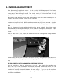
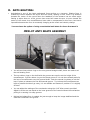
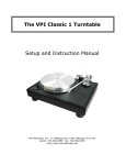
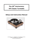
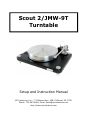
Scout 2/JMW-9T Turntable Setup and Instruction Manual VPI Industries, Inc., 77 Cliffwood Ave. #3B, Cliffwood, NJ 07721 Phone: 732-583-6895, Email: [email protected] http://www.vpiindustries.com Important: Read Before Proceeding! Read and follow the Safety Instructions below. Save all packing materials. The Scout 2 should only be moved or shipped in its original packaging to reduce the risk of damage in transit. The Scout 2 must be placed on a flat, level surface. This will make setup easy, provide better sound quality, and put less strain on the main bearing. Safety Instructions Follow the instructions below to reduce risk of electrical hazard or injury. To avoid electrical shock, do not open the motor housing. If the power cord provided with the Scout 2 does not reach an outlet, use a heavy-duty, grounded extension cord. To avoid electrical shock, always plug the Scout 2 into a grounded outlet. Do not expose the Scout 2 to rain or excessive moisture. Do not touch the male pivot point of the tonearm assembly. It is extremely sharp. Follow the instructions below to avoid damage to the Scout 2 Do not leave the Scout 2 running unattended. Use the Scout 2 in a well-ventilated area. Place the Scout 2 on a firm surface to allow proper ventilation to occur. Introduction The Scout 2 turntable is a precision instrument featuring the new Tapered arm tube version of the JMW-9 tonearm. It has been thoroughly tested and run for at least 4 hours. The speed accuracy, wow, flutter, and rumble have been checked, and this unit meets all of our specifications. Minimum Specifications Wow and flutter Less than .02%. Rumble Greater than 78db down. Speed accuracy Within .1%. Total weight 32 pounds. Platter run out +/- .001 inch. Product Specifications 600 RPM AC synchronous drive motor. Drive belt custom-made for VPI. Aluminum cone feet with stainless steel ball bearings on the bottoms. Solid aluminum platter with bronze bushings and Peek thrust surface. Platter sits on 60 Rockwell-hardened shaft and chrome-hardened ball bearing. Complete and return the warranty card. The warranty does not take effect until the warranty card is returned. UNPACKING THE BOX The turntable and tonearm are packed very carefully to avoid damage during shipping. It is important that you save the packing materials and box to use for shipping or moving the Scout. 1. Remove the 2 foam side pieces and foam block in the center. 2. Make space for the Scout 2 and remove the chassis from the box. Put the chassis down on a solid surface. Complete and return the warranty card. The warranty does not take effect until the warranty card is returned. 3. Remove and set aside the items in the next layer: Alignment Jig. Record clamp. Power cord. Bag containing screwdrivers and screws for mounting the cartridge. 4. Remove the pieces of foam covering the tonearm, then carefully remove the tonearm and set it down in a safe place. Use caution with the tonearm’s delicate wires and Lemo connector. 5. Remove the turntable platter and motor. Be very careful not to hit or damage the motor pulley. It measured +/- .0005” when it was tested at the factory. Try not to disturb it at all. SETTING UP THE SCOUT The Scout 2 must be placed on a flat, level surface. This will make setup easy, provide better sound quality, and put less strain on the main bearing. 1. Place the turntable chassis, with the square cutout on the left, on the shelf or stand where it will be used. The better isolation you provide the Scout, the better it will sound. We highly recommend a 1 to 3 inch thick maple shelf sitting on rubber isolator feet for this purpose. 2. Remove the tape from the spindle hole on the turntable platter and place the platter on the spindle. The platter bearing is lubricated; no additional lubrication is needed for at least one year. 3. Connect the power cord to the motor, then place the motor, with the power cord at the rear, next to the square cutout of the turntable chassis. 4. Lift the chassis and place it over the power cord. The motor should extend approximately .25 inch from the side of the turntable chassis. 5. Place the drive belt around the platter and around the pulley on the motor. The belt does not have to be level on the platter. It will self-level when the platter starts rotating. 6. For 33 RPM operation, place the belt on the upper part of the pulley. For 45 RPM operation, place the belt on the lower, wider part of the pulley. The center groove in each diameter is the correct speed. To determine the precise speed, use a strobe disc. The VPI Synchronous Drive System speed controller provides the ultimate speed accuracy and best sound. Check with your dealer about availability. 1 7. Verify the turntable is level by using a 9- or 12-inch bubble level front-to-back and side-toside on the platter. If it is not level, rotate the aluminum cone feet up or down. If you must turn the Scout feet more than three full turns, level the shelf or platform the table sits on first. A. CARTRIDGE MOUNTING: FOR CARTRIDGES WITH THREADED MOUNTING HOLES: Use the screws supplied by the cartridge manufacturer to mount the cartridge. Any other screws may not fit the thread properly and may even damage the threads and cartridge. USE ONE OF THE SUPPLIED WASHERS UNDER THE SCREW HEAD. For all cartridges with pass through mounting holes use the hardware supplied with the arm. Remember to use the washers under the screw heads to prevent damage to the finish on the JMW-9T arm. In this step, the connectors will be attached to the cartridge's terminals. Disregard the color of the insulators on the cartridge clips. B. THE COLOR CODE OF THE WIRES IS: RED = right hot GREEN = right ground BLACK OR WHITE = left hot BLUE = left ground IF YOUR PHONO SECTION INVERTS PHASE, THE HOT COLOR BECOMES THE GROUND COLOR Using tweezers or fine tipped pliers grip the center of the red wire's connector (do not grip the wire) and push it onto the cartridge's right hot terminal pin. In the same way, connect each of the remaining connectors to its respective cartridge terminal. Do not push the connectors all the way on, as this could damage the cartridge. Always back up the cartridge with your finger when pushing on the clips. The JMW-9tT tonearm comes with one large dropped counterweight installed on the rear shaft of the tonearm. For most cartridges you will only need this large weight. The counterweight is held in position by a setscrew. Pick up the arm tube, taking care not to strain or damage the fine 4-color wire and Lemo connector. For now, position the large counterweight as close to the bearing housing as you can (toward the front of the arm) but not touching the balance ring. The object here is to balance the arm while keeping the counterweight as close to the bearing housing as possible. This results in the least inertia for a given cartridge weight. In some rare cases it may be necessary to use two counterweights together or a larger counterweight. Contact your dealer if a second or larger counterweight is needed. 2 B. OVERHANG ADJUSTMENT: This adjustment will yield the lowest distortion in the last third of the record, the hardest to track, when playing a typical 12" record. Do not go crazy over this adjustment. You do not know if the stylus is aligned properly on the cantilever. You are also facing a constantly moving target when playing a record. The arm is moving in 3-dimensions and will only approximate the accuracy you have built into your alignment. Place the arm tube assembly on the lower bearing, taking care not to strain or damage the 4color wire and Lemo connector. Place the arm in its rest. At the rear of the arm base assembly is the connector block. Plug the Lemo connector into its receptacle on top of the block. Notice that the connector can plug in only one way. Align the red dots on the arms plug with the red dot on the receptacle. Push gently, do not force the plug. Place the Alignment Jig into position by sliding the narrow end with the circular cutout between the arms lateral balance weight and the platform that supports the armrest. Make sure that the jig's cutout fits against and around the bearing well and the hole is over the spindle. While the arm is in its rest, loosen the screws that hold the cartridge just enough that the cartridge can be moved back and forth. Carefully swing the arm over the grid at the far end of the jig and place the stylus as close to the dot in the center of the grid as possible. Using a lighted magnifier will make this job very easy. BE VERY CAREFUL NOT TO DAMAGE THE CARTRIDGE'S STYLUS: Move the cartridge so that the stylus rests on the dot. Now, viewing the cartridge from above, line it up so that its sides are symmetrically positioned between the lines of the grid. If the cartridge has parallel sides, these should be made parallel to the grid lines. Also make sure that the cartridge is centered between the sets of lines. If you can see the cantilever clearly you can align the cantilever to the alignment grid. This is difficult and may produce no increase in sound quality. 3 Double check the adjustments made above. The cartridge needs to be both centered and "square" between the gird lines and have the stylus resting on the dot. Place the arm back in its rest. Without letting the cartridge move, tighten the screws holding the cartridge to the arm head. Make it tight, but don't over do it and strip the threads or distort the cartridge body. FIG #2: THE PROPER WAY TO ALIGN A CARTRIDGE, ALIGN THE CARTRIDGE, NOT THE TONEARM HEADSHELL! SHOWN IN WHITE FOR CARITY. C. TRACKING FORCE AND AZIMUTH Place the arm tube assembly on the lower bearing, taking care not to strain or damage the 4color wire and Lemo connector. Place the arm in its rest. At the rear of the arm base assembly is the connector block. Plug the Lemo connector into its receptacle on top of the block. Notice that the connector can plug in only one way. Align the red dots on the arms plug with the red dot on the receptacle. Push gently, do not force the plug. Make sure the turntable is level. Refer to your turntable instructions and use a bubble level to check level. In most cases, the best place to put the level is on the platter. With a unipivot arm it is particularly important to level the turntable. Move the counterweight until the arm has a very slight downward tracking force, just enough to keep it from moving sideways on the platter or enough to keep it in the groove of the record Tracking force is adjusted by moving the counterweight forward and back just a bit at a time. At least initially, you will be setting the tracking force twice. The first time will be before the cartridge's overhang is set. After this is done, you will need to double check the tracking force and adjust it as needed. 4 The JMW-9T does not have a built-in tracking force gauge, but a Shure Stylus Force Gauge is supplied with your arm on a new unit. Following the gauge instructions set the tracking force to the cartridge manufacturer recommendation plus 1/10 of a gram more. We always recommend going to the high side when it comes to tracking force. High frequency vibrations can cause a light-tracking cartridge to cause more damage to the grooves than running a cartridge at a heavy setting. Make sure the damping fluid is not installed when setting this force. VERY IMPORTANT: MAKE SURE THE TONEARM IS PARALLEL TO THE PLATTER WHEN SETTING THE TRACKING FORCE. IF IT IS NOT THE END RESULT WILL BE HIGHER OR LOWER VTF THAN YOU WANTED. Next, the lateral balance or azimuth must be set. Because the phono cartridge is offset, there is an unbalancing force that tilts the arm to one side. For the cartridge to properly track the record groove, the stylus must be ninety degrees to the record surface. Move the counterweight so a slight tracking force is applied and the stylus just sits on the record surface. Tighten the setscrew in the counterweight enough so that it will not move on its own and without moving the counterweight forward or back rotate it around the shaft to set correct azimuth. Lay the long thin rod supplied behind the cartridge mounting screws into the V groove and use it as a guide for setting azimuth. Playing with this will give very accurate azimuth settings. Unlike other unipivot arms, the JMW’s lateral balance weight does not hang off to the side of the arm. Instead, its position around the bottom of the upper bearing housing places the weight below the pivot point. This increases mass below the pivot and increases arm stability. 5 D. ANTI-SKATING: Anti-skating is one of the least understood forces acting on a tonearm. Skating force is created by friction between the stylus and the record, causing a force vector in a direction towards the center of the record when the headshell of the tonearm has an offset angle. Putting a stylus down on a flat, groove less record will cause the arm to move toward the center of the record. Arm manufacturers have tried to compensate for this force, but that is impossible because the force is constantly changing as the music and velocity change. You now have the option of using a mechanical anti-skate for those that want it. JMW-9T ANTI SKATE ASSEMBLY You will see three rubber rings on the non-grooved straight shaft; these are used to set the anti-skating force. The two rubber rings on the shaft with the grooves are used to set the height of the monofilament. Set the rubber ring on the lowest groove if it is not there already and slip the loop of monofilament over the grooved shaft. Push the second ring down to lock the loop in place on between the first and second groove. Try to keep the monofilament as level as possible but don’t go crazy, it is not audible and causes no problem if it is slightly off level. You can adjust the settings of the mechanism using the 1/16” Allen wrench provided. Adjust it so the arm can travel to the inner grooves of the record without the mechanism pulling it or causing it to skip grooves. Minimal anti-skate force is needed, do just enough to keep the image stabilized and the cantilever centered in the groove. 6 E. ARM HEIGHT: Place a record on the turntable. Loosen the two setscrews in the base of the arm (right side and rear of base). Lower the arm onto the record and make the arm tube parallel to the record surface by rotating the wheel with the 4 prongs sticking out. This is a good initial setting. You may wish to vary it depending on the cartridge you are using and or the particular record being played. Remember to always retighten those two setscrews when listening. If they are left loose the sound will be unfocused. F. CONNECTING TO THE PREAMPLIFIER/AMPLIFIER ONLY USE INTERCONNECTS THAT ARE SHIELDED AND PROPERLY GROUNDED. NON-SHIELDED INTERCONNECTS CAN HUM AND PICK UP RF. The ground connection is available to eliminate hum if necessary. If hum is present, first connect a ground lead from the connector block to the preamplifier or amplifier to which the output cable is connected. If this does not eliminate the hum, run a ground wire from the turntable chassis to the connector block as well. The block's connector will accept bare wires, spade lugs, or ring tongue connectors. G. PLAYING RECORDS Before playing a record, make sure that the two setscrews in the arm base are tight. You can use either the paper, gray urethane, or no mat at all on your Scout 2. They sound different and one may work better in your system than the other. We prefer no mat at all or the paper mat. Place the rubber washer on the platter spindle, then the record on the platter, then screw the clamp onto the spindle. The clamp will lock the rim of the record down first forcing the air out and acting like a vacuum. Press the power button and sit down and enjoy listening to your records! H. GENERAL USE Allow at least 20 hours of break-in time. The motor will make some low-level noise. This will not get into the system. The motor and bearings will become quieter as you use your Scout 2. After at least one year of use, the platter bearing and motor will need to be lubricated. For the platter bearing use a small amount of white lithium grease placed on the ball. For the motor, use 1 drop of 40-weight motor oil below the brass piece. 7 Additional Items Available from Your Dealer The VPI Synchronous Drive System power supply provides a major increase in musicality by feeding the synchronous motor a perfectly stable wave form at the frequency you choose. The SDS lets you change speed electronically. The HR-X periphery record clamp will fit the platter of the Classic 1 and provide a vacuum-like grip on the record. The clamp removes all warps and damps the record to prevent ringing. 8 VPI Industries, Inc. Limited Warranty VPI Industries, Inc. (VPI) warrants this unit against defects in materials and/or workmanship for three (3) years from the date of purchase by the original retail purchaser. VPI’s sole obligation under this warranty is limited to the repair or replacement, at VPI’s option, of any part(s) found to be defective. VPI’s obligation to repair or replace defective parts is the purchaser’s sole and exclusive remedy, and VPI shall not be liable for any direct or indirect injury and/or property damage arising out of the use of the product or defect in or failure of the product. This warranty does not extend to any unit whose serial number has been defaced or altered. Any product that VPI determines causes a defect or malfunction due to incorrect installation, modification, misuse, or servicing by the purchaser, or service technician not authorized by VPI to perform such service will not be warranted. This warranty does not cover trivial or cosmetic defects that do not impair the unit’s normal function. VPI reserves the right to make changes in this product without assuming any obligation to install such change in any product previously manufactured. This warranty to repair or replace defective parts is in lieu of all other express or implied warranties of merchantability or fitness for a particular purpose. There are not warranties that extend beyond the description herein. Some states do not allow exclusion of implied warranties or limitation of incidental or consequential damages, so the above exclusion or limitations may not apply to you. This warranty gives you specific legal rights, and you may also have other rights that vary from state to state. Register your Product Online: http://vpiindustries.com/warranty/ 9