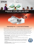
1
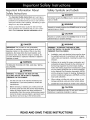
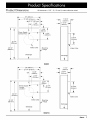
Installation
Instructions
Remote Blowers
Models: REMP3, REMP16
Suitable for use in a household cooking area.
Suitable for use with solid state controls.
To complete this blower, a Dacor ® hood assembly or Dacor raised vent must
be purchased separately. See the hood or raised vent installation instructions
to determine suitability.
Part No. 65265
Rev. G
Important Safety Instructions ..........................................
Important Information About Safety Instructions ..............
Safety Symbols and Labels .............................................
General Safety Precautions .............................................
Product Specifications
.....................................................
Product Dimensions .........................................................
Installation Planning and Preparation .............................
Electrical Supply Requirements .......................................
Installation Planning .........................................................
Installation Preparation ....................................................
1
1
1
2
3
3
4
4
4
5
Installation Instructions ....................................................
Parts List ..........................................................................
Installation ........................................................................
Verifying Proper Operation ...............................................
Technical Data ...................................................................
6
6
6
7
8
Important:
•
Installer: In the interest of safety and to minimize problems, read these installation instructions completely and carefully before you begin the installation process. Leave these installation instructions with the customer.
•
Customer:
Keep these installation instructions for future reference and the local electrical inspector's use.
If You Need Help...
Model Identification
If you have questions or problems with installation, contact
your Dacor dealer or the Dacor Customer Service Team. For
repairs to Dacor appliances under warranty call the Dacor
Distinctive Service line.
REMP3 = Remote blower with 8-inch diameter intake
REMP16 = Remote blower with 10-inch diameter intake
Dacor Customer Service
Phone:
(800) 793-0093
Monday -- Friday 6:00 A.M.to 5:00 P.M.Pacific Time
Web site:
www.Dacor.com
Dacor Distinctive Service (for repairs under warranty only)
Phone:
(877) 337-3226
Monday -- Friday 6:00 A.M.to 4:00 P.M.Pacific Time
All specifications
subject to change without notice. Dacor assumes no liability for changes to specifications.
© 2008 Dacor, all rights reserved.
Important Information About
Safety Instructions
The Important Safety Instructions
and warnings in
these instructions are not meant to cover all possible
problems and conditions that can occur. Use common
sense and caution when installing, maintaining or operating this or any other appliance.
•
Always contact the Dacor Customer Service Team
about problems and conditions that you don't understand. See Customer Service Information above.
Safety Symbols and Labels
[_
WARNING
WARNING
CAUTION
I
I
personal injury or property damage:
I
[_
WARNING
WARNING - TO REDUCE THE RISK OF FIRE,
ELECTRIC SHOCK, OR INJURY TO PERSONS,
OBSERVE THE FOLLOWING:
a.
Installation work and electrical wiring must be done
by qualified person(s) in accordance with all applicable codes and standards, including fire-rated construction.
b.
Sufficient air is needed for proper combustion ana
exhausting of gases through the flue (chimney) of
fuel burning equipment to prevent back drafting.
Follow the heating equipment manufacturer's guideline and safety standards such as those published
by the National Fire Protection Association (NFPA),
and the American Society for Heating, Refrigeration
and Air Conditioning Engineers (ASHRAE), and the
local code authorities.
c.
When cutting or drilling into wall or ceiling, do not
damage electrical wiring and other hidden utilities.
d.
Ducted fans must always be vented to the outdoors.
WARNING
WARNING. TO REDUCE THE RISK OF FIRE,
ELECTRIC SHOCK, OR INJURY TO PERSONS,
[_
at:service
Pane ! and !0Ck the service disconnecting
means to prevent power from being switched on
acddenta!!y, when the service disconnecting means
cannot be locked; secure!y fasten a Pr0minent warn ing
device, such as a tag, to the service panel,
I
Hazards 0r Unsafe practices that COULD resUlt in minor
TO REDUCE THE RISK OF FIRE, USE ONLY METAL
DUCTWORK:
[_
I
Hazards 0r Unsafe practices that COULD result in severe
personal injury or death.
[_DANGER
[_
n severeperso na
injury or death ...........................
[_
IMPORTANT: Do not store or use combustible,
flammable 0r explosive vapors and liquids (such as
gasoline) inside or in the vicinity 0f this orany other
appliance. Also keep items that could explode, such
as aerosol cans, away from the range or co0ktop, Do
not store flammable or expl0sive materials in adjacent
cabinets or areas. ..................
I
[_ DANGER
Immediate hazards that WILLresut
CAUTION
For general ventilating use only. Do not use to exhaust
hazardous or explosive materials or vapors.
READ AND SAVE THESE INSTRUCTIONS
i_=lc'l_r.
1
General Safety Precautions
To reduce the risk of fire, electric shock, serious injury or death when using this blower, follow basic safety precautions,
including the following:
WARNING
Do not install or 0perate this unit if ithas been dam,
aged, dropped, has damaged electrical wiring or
is not working properly. If the product is damaged
when received, immediately contact the dealer or
'
• Before
installing or servicing the in-line blowe r,
make sure that power to the wiring is turned off at
the circuit breaker or fuse box. Make sure that the
service panel is locked or tagged to prevent power
'
from being switched on accidently.
reduce the risk of electric Shock Or firel the total
combined current draw of the in-line blower and the
hood or downdraft vent must not exceed the maximum rated input current of the hood or downdraft
vent.
The installer must show the cust0mer the location
of the fuse or circuit breaker panel so that the customer knows where and how to turn the Power off.
2
•
A minimum of two people are required to safely
install this appliance.
•
Never allow the filters or vent openings on the hood
or downdraft vent to become blocked or clogged.
Do not allow foreign objects, such as cigarettes or
napkins, to be sucked into the vent holes.
builder.
Install or locate this appl ante only in accordance
with these installation instructions and the Dacor
hood or downdraft vent installation instructi0nsl
Improper installation, adjustment, alteration, service
or maintenance can cause serious personal injury or
property damagel
•
WARNING
_mC_
Tape all duct joints securely to prevent combustion by-products, smoke or odors from entering the
home. Doing so will also improve system efficiency.
•
Do not route electrical wiring near hot surfaces.
•
Do not ground the appliance with the neutral (white)
house supply wire. A separate ground wire must be
utilized.
•
To prevent a damaged or non-functional system,
complete electrical connections properly. Follow
the wiring diagrams carefully in the hood or in-line
blower installation instructions to ensure a proper
installation. After installation or service make sure
that all blower wires are tightly connected to their
respective terminals.
Product Di mensions
-_17
All tolerances: +1/16",-0,
19 (483mmj
3/8" (441mm)_
.__
9 1/2" (241mm)
7 1/2"
I-I
'-
h_
_
5 13/16"
(202mm) _1(148mm)
(191mm)I- V
3 5/8"
I
., --_
Power SupplyL,_"
Conduit
7 15/16"
I
€
(1.6 mm,0) unless otherwise noted.
(92mm)
-f
9 1/4"
(235mm)
Hole/_..
8" Nom.
(203mm)
24 1/4"
(616mm)
_!
/s
Intake
25 1/2"
(648mm)
Collar
/
Mounting
Flange
Intake Collar
Discharge
Discharge
REMP3
.q_24
26" (660mm)
1/4" (616mm)-_-
11 1/2"
-- _
(333mm)
9 9/16"
(292mm) _1(243mm)
9 1/2"
(241 mm)
_
13 1/8"
q-
3 5/8"
(92mm)
Power Supply _'";'
Conduit
Location,,,"
--CE
-_- _--..
/
12 1/4"
(311mm)
10" Nom.
"'",
32 1/4"
(819mm)
(25_mm)
/
Intake Collar
33 1/2"
(851mm)
\
Intake Collar
Mounting
/Flange
Discharge
Discharge
REMP16
_mCD_
3
Electrical Supply Requirements
The power for this blower is supplied via 1/2" 3-wire
wiring/conduit (not included) by an approved Dacor
hood or raised vent. The wiring/conduit is installed
between the hood or raised vent and the blower and
Installation Planning
System Layout
WARNING
shall be terminated on each end by a 1/2" UL certified strain relief. The power is turned on and off by the
power switch on the approved ventilation device.
To avoid the risk of fire due to the unit overheating:
•
The correct voltage, frequency and amperage must be
supplied to the hood or raised vent and the blower from
a grounded, single phase circuit that is protected by a
properly sized circuit breaker or time-delay fuse. The
circuit must have the capacity to supply the combined
power requirements for the hood or raised vent and the
in-line blower. See the installation instructions for the
hood or raised vent to determine total power requirements in combination with the blower electrical specifications.
Model
Number*
Power
Requirements**
DO NOT install more than one blower to increase
the length of the duct run. Even small differences
between blower air flow rates can greatly reduce the
air draw by the hood or raised vent.
Consult the installation instructions for the raised vent
or hood for complete layout and duct system planning instructions. Observe all location and duct system
design instructions.
The remote blower needs to be wired to turn on when
the raised vent or hood is turned on by routing wiring/
conduit parallel to the duct work. Connect the wiring/
conduit to the raised vent or hood on one end and the
remote blower on the other. There is a 7/8" electrical
access hole on the bottom of the blower.
Blower Rating***
REMP3
120 Vac, 60 Hz,
3.8 Amp
600 CFM
REMP16
120 Vac, 60 Hz,
2.7 Amp
1000 CFM
Blower Location and Mounting
•
*
All models are thermally protected.
**
In addition to the hood or raised vent
***
Nominal rating at 0 inches static pressure. See
Technical Data section for actual ratings.
The above specifications are for reference only, See the
data label on the blower for exact specifications. If the
above specifications vary from the label on the blower, use
the data on the blower label.
It is the owner's responsibility to ensure that the power
supply is installed by a licensed electrician. The electrical installation must comply with the latest revision of the
National Electric Code ANSI/NFPA 70 (latest revision) and
local codes and ordinances.
A copy of the specification may be obtained from:
DO NOT install this blower with a hood or raised
vent that has an internal blower.
Install the blower in a location that allows it to be
accessed for service if necessary. There must be
enough room to remove the top cover of the unit
and enough room to access the power terminals and
mounting holes located inside.
•
The mounting location needs to allow for a cutout
under the unit for the duct and wiring/conduit to pass
through the wall or roof into the blower assembly. See
Figure 1.
•
The mounting location must allow for a clearance of at
least 15" (381mm) between the blower air discharge
and any obstructions (vents, pipes, etc.) See below.
Duct and wiring passing
through cutout \
/ _
\
IWall
National Fire Protection Association
1 Batterymarch Park
Quincy, Massachusetts
02269-9101
If the electrical service provided does not meet all product
specifications, or does not conform to the NEC or local
standards, do not proceed with the installation. Call a
licensed electrician to correct the electrical service before
proceeding.
J"
Discharge, no obstructions
within 15 inches
Example of Roof
Installation
4
_mC_
_L_J
-_
Example of Wall
Installation
o
Blower Location and Mounting
•
Select a location that can properly support or can be
reinforced to support the weight of the blower (see
weight table below). The unit requires a mounting surface around the perimeter of the base of the unit 2"
in width and thick enough to accommodate the 8, 2
1/2" long mounting screws that are provided with the
unit. All contact surfaces between the blower and any
mounting surfaces must be solid and at right angles.
See Figure 1 for the required mounting surface dimensions.
Model Number
Approximate
The blower must also be mounted vertically or at a
pitch of 2:12 or greater. If the pitch of the mounting surface is less than 2:12, construct a roof curb to mount
the blower. See Installation Preparation for exact
dimensions.
(cont.)
Shipping
REMP3
35 Ibs.
REMP16
55 Ibs.
•
When mounted in a exposed location shield it to prevent the accumulation of water in the chassis. On
horizontal installations, point the discharge in the same
direction as prevailing winds. When mounted vertically,
the discharge must point down.
_.q-_
__.-"
"_:_"
-_""
Weight
"_:: ._.-.'-M
_i
_ ':°::_"?
-"_4_-:"%:
:: '°"?i_,_j_
_._,_-......:
:._:--.;_
Weight Table
_.._-.
_ 9:-_-':
• _:_-.
•:.._.:.-:..._:.:_..,_.,
" _?.::
::-.
oischar0e
,owe--
A
Figure
2: Installation
Roof Cu rb
"""-""
:
with Roof Curb (for fiat rooN)
Installation Preparation
................................ -:-"
Prepare the mounting surface and reinforce it if necessary according to the Blower Location and Mounting
specifications starting on page 4.
2.
Make a cutout in the center of the mounting location
according to Figure 1.
3.
On roofs with a pitch of 2:12 or less, construct a roof
curb according to the specifications below. Attach it to
the mounting surface and seal it around the base.
D
F
B
Duct and
Conduit
Cutout
1.
Reinforced
Mounting
Surface
j
"(51mm)
25 1/2"
(648mm)
I
i
z'
Figure 3
1
2" (51 mm)
around entire
perimeter
I
,
i
,
I
(152mm)
2 II
(51mm)
Discharge
Side
23 t/4"
Figure 1 :
Required Mounting Surface Dimensions
Dimension
REMP3
REMP16
A
19" (483mm)
26" (660mm)
B
25 1/2" (648mm)
33 1/2" (851mm)
C
4" (102mm)
4" (102mm)
D
2 1/8" (92mm)
2 1/8" (92mm)
E
11" (279mm)
13" (330mm)
F
12 5/8" (321mm)
16 5/8" (422mm)
REMP3
Roof Curb
33 1/2"
(851mm)
2 II
The base of the remote blower needs to be sealed with
mastic or the equivalent to prevent leaks.
(51mm)
30 t/2"
REMP16
Roof Curb
(660mm)
,
[_
•
WARNING
Remove the blower's top cover by removing the screws
around the edge that hold it in place.
If the electrical service provided does not meet the
power requirements for the hood/raised vent and the
blower combined, do not continue with the installation. Contact a licensed electrician to correct the
situation before continuing.
Failure to connect the wiring as specified may result
in an electric shock hazard and/or improper blower
operation.
•
To avoid the risk of fire or electric shock, turn off
power at the circuit breaker panel or fuse box before
connecting the blower to the power source.
•
The blower assembly is heavy. Do not attempt to lift
or move it without assistance.
Parts List
Figure 6
Verify Package Contents
•
2 1/2" wood mounting screws (8)
•
Blower assembly
,
Apply sealant between the blower and the mounting
surface where the flange around the edge of the blower
will rest.
Parts Required
•
Flange
3 conductor wiring/conduit with UL certified strain relief
on each end (length is determined by remote blower
location).
Sealant
If the blower will be mounted to a surface other than
wood, fasteners designed for the material the unit will
be mounted to must be provided. The fasteners must
be capable of supporting the weight of the blower (see
weight table on page 5) and meet local codes and ordinances.
•
45 ° Adjustable
Elbow
Consult the hood or raised vent installation instructions
Roof
for additional part requirements.
Installation
Round Duct
Figure 7
,
Before installing the blower, unpack the unit and check
for physical damage to the motor and blower assembly.
To do so, reach in through the intake collar and spin
the fan blades slowly. They should spin freely and quietl_ without vibration.
,
,
O
Intake
Collar
,
Blades
Fan
__
o
Figure 5
Bottom of Blower
O
6
_mC_
Pick up the blower assembly and center it on the
mounting surface inserting the intake collar into the
cutout.
While holding the blower in place, fasten it to the
mounting surface with eight (8) mounting screws. The
mounting holes are located inside the blower assembly
chassis near the sides.
Install the duct work according to the installation
instructions for the hood or raised vent. Support the
duct weight as necessary to ensure properly sealed
joints.
Electrical Installation
7.
,
,
Run the wiring used to supply power from the installed
raised vent or hood to the blower parallel to the duct
work.
12. Connect the white (neutral) wire to the N2 blower
power terminal (see Figure 9). Tighten the terminal
screw firmly into place. IMPORTANT: The neutral (N2)
terminal on the blower has the BLACK wire from the
blower wiring harness connected to it.
Make sure that power to the raised vent or hood is
disconnected or turned off at the circuit breaker or fuse
box.
13. Connect the green (GND) wire to the GND blower
power terminal (see Figure 9). Tighten the terminal
screw firmly into place.
With the UL certified strain relief attached to the end
14. Check the wires from the blower wiring harness to
make sure that they are firmly attached to the terminal
according to Figure 9. Reconnect any wires that are
loose. Make sure all terminal screws are tight.
of the wiring/conduit, feed the wires into the electrical
access hole on the under side of the blower and attach
it.
15. Replace the blower's top cover and screws.
16. Secure the other end of the wiring/conduit to the hood
or raised vent and connect the wires according to the
hood or raised vent installation instructions.
Verifying Proper Operation
Wiring/conduit
connected to blower
I
Figure 8:
Wiring/Conduit Connection
10. From inside the blower assembly, strip the three wires.
11. Connect the black (L1) wire to the L2 blower power terminal (see Figure 9). Tighten the terminal screw firmly
into place. IMPORTANT: The L2 (hot) terminal on the
blower has the BLUE wire from the blower wiring harness connected to it.
,-
Read the raised vent or
[_
WARNING
completely before operation.
Test the blower operation according to the Verify Proper
Operation section of the hood or raised vent installation
instructions.
If the blower does not work after having been properly
installed, contact Dacor Distinctive Service at (877) 3373226. Do not attempt to repair the unit yourself. Dacor is
not responsible for the costs required to correct problems
caused by a faulty installation.
Wires from
hood/raised
vent
¢
co
t
t
t
L2
N2
GND
Not
Used
Green
To blower
wiring harness
Figure 9: Wiring Diagram
_mCD_
7
REMPSeries Blower Ratings
Model
Number
Nominal
Rating*
Actual
Rating*
REMP3
600 CFM
620.5 CFM
REMP16
1000 CFM
994.8 CFM
At 0" static pressure
REMP3 Blower Performance
REMP16 Blower Performance
_- 5.0
_- 2.5
.4--,
(5
--o 4.0
_2.0
o
(/)
09
..C
r-
=o1.5
c° 3.0
i
_if? 2.o
1.0
u)
Q.
o 1.0
o 0.5
.+._,
(u
_J
4--.-'
cO
0
100
200
300
400
500
Airflow CFM (Cubic feet/minute)
8
_mC_
600
7O0
200
400
600
800
1000
Airflow CFM (Cubic feet/minute)
4#
The Life of the Kitchen?
Dacor
• 1440 Bridge Gate Drive, Diamond Bar, CA 91765
• Tel: (800) 793-0093
• FAX: (626) 403-3130
• www.Dacor.com