1
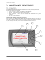
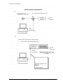
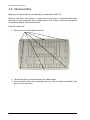
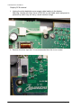
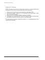
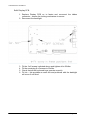
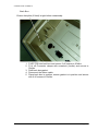
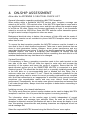
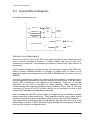
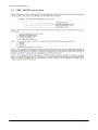
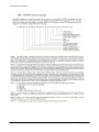
SMARTFIND
GMDSS NAVTEX
Service Manual
Commercial in confidence
Table of Contents
1.
Introduction ........................................................................................................ 4
1.1. Scope ............................................................................................................ 5
1.2. Applicability ................................................................................................... 5
1.3. Product History.............................................................................................. 5
1.4. Servicing equipment...................................................................................... 5
1.5. Safety notices................................................................................................ 6
2. Assessment ........................................................................................................ 7
2.1. Maintenance tasks ........................................................................................ 7
2.2. Routine testing .............................................................................................. 7
2.3. Assessment................................................................................................... 7
3. Maintenance procedures ................................................................................... 9
3.1. Inspection...................................................................................................... 9
3.2. Functional test ............................................................................................. 10
3.3. Disassembly ................................................................................................ 12
3.4. Reassembly ................................................................................................ 17
3.5. Leak Testing................................................................................................ 20
3.6. Factory Reset .............................................................................................. 20
3.7. Receiver alignment – checking only ............................................................ 20
3.8. System Restart............................................................................................ 21
3.9. Software Download ..................................................................................... 21
4. On-ship assessment ........................................................................................ 22
5. Fault finding...................................................................................................... 24
5.1. On-ship fault finding .................................................................................... 24
5.2. Fault finding in workshop ............................................................................ 25
5.3. System Block Diagram ................................................................................ 27
5.4. Service Bulletins.......................................................................................... 28
5.5. Software Release Notes ............................................................................. 29
6. Repair procedures............................................................................................ 29
7. Spares ............................................................................................................... 30
Appendix 1: Specification....................................................................................... 31
Appendix 2: MESSAGE STRUCTURES.................................................................. 32
Appendix 3: Sea Trial Check List ........................................................................... 36
This document is McMurdo Ltd copyright (©) and contains proprietary owned intellectual property rights and confidential data.
All rights are strictly reserved. The information must not be used except for the agreed purpose. Unauthorized use,
reproduction or issue to any third party is not permitted without the prior written authority of McMurdo Ltd. This document is to
be returned to McMurdo Ltd when the agreed purpose is fulfilled.
SMARTFIND NAVTEX service manual
Page 3
Commercial in confidence
1. INTRODUCTION
NAVTEX is a method of transmitting navigational warnings and weather forecasts
from designated coast radio stations. All English language transmissions are made
on 518 kHz. Each station is allocated several time ‘slots’ during the day, when it is
permitted to transmit; these are normally at four hourly intervals. The only exceptions
to this are gale warnings and search and rescue messages, which may be
transmitted at any time. Subject to IMO approval, additional local language
transmissions may be made on 490 kHz and on 4209.5 kHz.
Reception of NAVTEX is normally limited to an area of 200 - 300 miles radius around
each transmitting station, although greater ranges are possible at night.
The SMARTFIND NAVTEX has been designed to the latest European and
International specifications to provide up to date weather and marine safety
information to commercial vessels. It meets IMO requirements under GMDSS: IMO
MSC.148 (77) and IEC 61097-6 (Ed 2.0).
Installation is straight forward. Connect the SMARTFIND NAVTEX to a 12 or 24 volt
DC supply and connect a suitable antenna. Switch it on, and it will start displaying
and storing NAVTEX messages without further manual intervention. Note that if there
are only a couple of NAVTEX stations within range it may be several hours before the
first message is received.
If you are within a sea area where you are able to receive messages from multiple
NAVTEX stations (particularly at night), you may be quickly overwhelmed with
information. It can therefore be set up to display only those stations and message
categories you want to receive and which are applicable to the sea area in which you
are sailing.
Normally, routine messages are repeated at four hourly intervals. Provided that the
SMARTFIND NAVTEX is left running, repeated messages are not displayed more
than once. Each message is retained for three days (72 hours) after its last reception
before being automatically deleted, unless the message has been marked as locked.
The SMARTFIND NAVTEX can be installed with either the bulkhead-mounting
bracket or the flush panel mounting kit provided with the product.
The SMARTFIND NAVTEX contains 3 receiver channels, tuned to 490 kHz, 518 kHz
and 4209.5 kHz. The SMARTFIND NAVTEX will receive on all 3 frequencies
simultaneously in those parts of the world where transmissions are available.
The SMARTFIND NAVTEX is capable of being connected to an Integrated Bridge
System (IBS), transferring NAVTEX messages to other navigational aids if required.
Note that the IBS must be compliant with the serial port requirements of IEC61097-6
(Ed 2.0).
The SMARTFIND NAVTEX will accept UTC time & date information from the IBS port
if available. UTC time & date will be used to timestamp received NAVTEX messages.
Note: The USB port on the back of the unit is not operational.
SMARTFIND NAVTEX service manual
Page 4
Commercial in confidence
1.1. Scope
This manual provides the instructions to enable routine and emergency servicing of
the NAVTEX equipment listed below. This manual represents the original equipment
manufacturer’s (OEM) service documentation applicable to these products.
1.2. Applicability
This manual applies to the following NAVTEX equipment:
i
McMurdo SMARTFIND NAVTEX Part number 93-001-001A
1.3. Product History
10/07/2010 – Entered production.
06/04/2011 - 93-721Z issue 2, routine software update released as V12.25.
1.4. Servicing equipment
The following tools and equipment are required to carry out the servicing detailed in
this procedure.
Equipment:
Active antenna (93-062A or 93-63A or equivalent)
Bench power supply, 12-24V @ 2 Amps minimum
RS232/USB to RS422 converter and cable (93-058A) to connect to a PC.
Multimeter
Handtools:
Calibrated torque driver (40-50cNm) with attachments:
5mm A/F socket
Small cross-headed screwdriver (No.1 Pozidrive)
Optional
PC with NMEA send/receive program or GPS data
Navtex message sender (Futronic GMDSS testbox or PC – see 3.2)
SMARTFIND NAVTEX service manual
Page 5
Commercial in confidence
1.5. Safety notices
Please read the following information for your safety:
This product has been assessed as presenting negligible hazard in a sealed
serviceable state.
Safety analysis
The following table summarises the nature of the hazard which may be present when
the unit is opened or serviced; each hazard is discussed at greater length in the
detailed sections.
Hazard cause
High Voltage
Hazard identification
Risk of shock
Precautions
Handle appropriately,
contact
avoid
General precautions for chemical agents (adhesives, greases, IPA)
Observe all safety precautions relevant to the country of operation. As a general rule,
protective overalls, gloves and goggles should be worn when handling chemical
agents, but different countries may have additional requirements which must be
observed.
Ensure that all chemical agents are handled in accordance with the manufacturer's
instructions, and that suitable protective clothing is worn.
Make sure that the working area is well ventilated, and that chemical substances are
not left exposed. Observe good hygiene practices; do not eat, drink or smoke when
handling chemicals.
Read the manufacturer's instructions before using any chemical agent.
Wear goggles
Wear overalls
Wash hands
Wear gloves
1.6. Anti-static precautions
The electronics section of the SMARTFIND NAVTEX is sensitive to electrostatic
discharge (ESD) which can cause immediate or hidden long term damage. It is
important that the PCB is only handled under suitable anti-static conditions.
Ideally, a fully grounded workstation, which has conductive
surfaces to avoid the build up of static charge, should be used.
As a minimum, the operator must be connected to a good earth
point through a resistance of 1MOhm. This is usually achieved
by wearing a suitable wrist strap.
SMARTFIND NAVTEX service manual
Page 6
Commercial in confidence
2. ASSESSMENT
2.1. Maintenance tasks
Service providers are reminded that it is their responsibility to ensure that the
procedures herein are followed, that only McMurdo Ltd approved parts are fitted, and
that good practice is observed.
The functions which can be performed by service providers are:
i
i
i
i
i
Routine testing
Software updating
System set up
Fault diagnosis
Repair
2.2. Routine testing
The SMARTFIND NAVTEX has automatic Built In Test Equipment (BITE).
BITE runs all the time in the back ground and monitors for correct operation of the
receiver sub systems including the monitoring of antenna supply current.
In the event of an error being detected;
i
i
i
i
i
A fault indication icon may be displayed on screen
Front panel LED may flash (according to menu set up option)
Buzzer may sound (according to menu set up option)
Detail of the alarm event is displayed under the Alarm mode, current alarms
page.
Alarm events are sent over the data interface output port(s) using the ALR
sentence format.
Whatever the reason for the return the SMARTFIND NAVTEX must be subjected to
a full assessment before any other action is taken. The agent has the responsibility to
ensure the SMARTFIND NAVTEX is completely serviceable and is fit for its purpose.
Included in the user handbook are full details of:
i Installation
i Set-up
i Operation
Therefore these items are not repeated in this manual.
2.3. Assessment
Every SMARTFIND NAVTEX returned for servicing must be fully assessed to
determine its operational status.
Assessment form
The assessment form, shown on the next page, is an essential tool in performing
diagnosis. It may be used to support customer billing and must accompany any
warranty return to the manufacturer.
SMARTFIND NAVTEX service manual
Page 7
Commercial in confidence
SMARTFIND
NAVTEX
ASSESSMENT
Ref
Date
Customer
Address
Type
Serial No
Antenna type:
Vessel name:
Customer comments
Warranty
claim
Return to Customer?
YES/NO
INSPECTION/DIAGNOSIS
Items Returned
x
x
x
x
Main unit
Antenna/bracket
Power cable
Manual
Item Condition
Software version:________________________
DIAGNOSIS
FUNCTIONAL TEST
ATE (in factory only)
Functional Test
Burn-in
Comments
New Parts Fitted
RF PCB
Keypad
LCD
Display PCB
Gasket
Backbox
Conclusions
x
x
x
x
x
x
PCB Serial no’s:
Assessed by
Signed
Date
Pass
SMARTFIND NAVTEX service manual
Fail
Page 8
Commercial in confidence
3. MAINTENANCE PROCEDURES
3.1. Inspection
The SMARTFIND NAVTEX should be inspected prior to any servicing/repair work.
The following should be inspected:
i Case – ensure no cracks in the plastic or other damage
i Screen – inspect display for damage and condition
i Rear connectors – ensure pins are straight and connectors are in good
condition
i Key pad - check operation
SMARTFIND GMDSS NAVTEX Operation
When powered, the SMARTFIND GMDSS NAVTEX will begin boot up. The start up
page will be displayed which shows the company address and telephone numbers
(7), the company name (8), and the current installed firmware release (9).
1
8
2
9
mcmurdo
3
mcmurdo
4
SMARTFIND
GMDSS NAVTEX
McMurdo
Portsmouth
PO3 5PB
Tel 023 92 623 900
Fax: 023 92 623 998
Email [email protected]
SMARTFIND GMDSS NAVTEX
7
GMDSS NAVTEX
SMARTFIND NAVTEX service manual
5
6
Page 9
Commercial in confidence
1. 4 Soft keys. Used to select various menus and options. The function of each
is displayed on the screen next to the key.
2. Display key. Press and release to control the back light. Press and hold to
control the contrast and brightness of the display. Also used to switch between
day and night mode.
3. Cursor key (Up/Down) used to navigate the display and to control brightness
when the display key pressed.
4. Cursor key (Left/Right) used to navigate the display and to control contrast
when the display key pressed.
5. SMARTFIND GMDSS NAVTEX Status LED. Indicates unit is booting up,
Alarm activation, messages etc…
6. Enter Key. Used to confirm data entries, Acknowledge incoming messages,
Press and hold to enter engineering service mode. You will be prompted for a
password which is SERVICE. Use the cursor key pad to move around the
onscreen keyboard.
3.2. Functional test
It is recommended that the unit is set up with an active antenna and tested to ensure
that messages are received on all channels and decoded correctly.
Alternatively a PC can be set up with a signal generator to test the receivers.
Please see the following page.
An external GPS and printer used to test the two data communications ports (COM1
& COM2).
The following should be checked:
i
i
i
i
i
Check receiver operates OK on all 3 channels
Check basic controls
Check LCD contrast and brightness – ensure LCD temp does not exceed
+70C ( back light life rating is 20,000 hours continuous operation).
Check time and date (note that there is no back up battery in the SMARTFIND
NAVTEX, therefore the time and date will be incorrect after a power cycle)
Ensure data ports COM1 & COM2 operate correctly
The following section shows an example of a test setup which can be used to
simulate NAVTEX messages (example is for 518kHz).
Caution: 12VDC is present on antenna connector whenever antenna power is
“enabled” in the setup menu. Care should therefore be taken when connecting to
external test equipment that can be damaged by DC voltage across its input. If in any
doubt, set antenna power to “disabled” before making the connection.
SMARTFIND NAVTEX service manual
Page 10
Commercial in confidence
SMARTFIND NAVTEX service manual
Page 11
Commercial in confidence
3.3. Disassembly
Warning: the backlight for the display is powered by 250V AC.
Observe Anti-static precautions, a clean room environment is recommended when
opening the case especially when replacing the LCD screen. Isolate the equipment
by disconnecting all outside connectors.
Back Box removal
1. Remove the 6 off self tapping screws
2. Lift off the back box and disconnect the ribbon cable.
3. Care should be taken not to damage the seal. This normally is retained in the
groove in the rear case
SMARTFIND NAVTEX service manual
Page 12
Commercial in confidence
RF PCB Removal
1. Remove the 4 off connector clamps (see above) using 5mm socket or nut
runner.
Connector clamps
2. Remove the 3 off screws from the PCB. Note that one screw may be secured
into a pillar and so will be of a different type.
SMARTFIND NAVTEX service manual
Page 13
Commercial in confidence
Display PCB removal
1. Unplug the white backlight power supply cable leading to the display.
Warning: Handle with care, there is 250V AC on this cable when equipment is
powered up and it may still carry a small residual charge.
2. Remove the silver tape link. It is recommended that this is not reused.
SMARTFIND NAVTEX service manual
Page 14
Commercial in confidence
3. Release the lock and disconnect the ribbon connector. Slide clamp as
indicated below
4. Remove the 11 OFF self tapping screws.
SMARTFIND NAVTEX service manual
Page 15
Commercial in confidence
Removal of LCD Screen
NOTE: This should only be done in clean room conditions – any dust present may
be attracted to the screen and will show up when next powered up.
1. Follow previous instructions to remove back box and display PCB.
2. Remove the keypad – this lifts out. Pull carefully from top and bottom – take
care not to tear the keypad.
3. Remove the 4 off screws and washers retaining the display.
4. The display can now be lifted out. If the LCD is being re-used cover the screen
immediately to protect from dust or place in a anti-static bag.
The fascia/window assembly is supplied complete – if it is damaged please order
a replacement assembly.
SMARTFIND NAVTEX service manual
Page 16
Commercial in confidence
3.4. Reassembly
Reassemble fascia/display
1. If fitting new fascia/window remove protective film from inside of
screen before fitting LCD.
2. Fit ribbon cable to display. Ensure that the insulated side is away
from the PCB.
3. Remove film from LCD and place LCD on to fascia.
4. Secure 4 off screws and washers to 50cNm.
5. Fit the keypad and press home securely. Ensure that the top of the
pillars are level with the top of the keypad.
SMARTFIND NAVTEX service manual
Page 17
Commercial in confidence
Refit Display PCB
1. Replace Display PCB on to fascia and reconnect the ribbon
connector – ensure the locking mechanism is secure.
2. Reconnect the backlight.
3.
4.
5.
6.
Fit the 2 off screws indicated above and tighten all to 50cNm.
Fit the remaining 9 off screws to 50cNm.
Check that all the keyboard keys operate correctly.
Fit link – this provides an earth link and problems with the backlight
will occur if not fitted.
SMARTFIND NAVTEX service manual
Page 18
Commercial in confidence
Back Box
Ensure that pillar (if fitted) is tight before reassembly.
1. Fit RF PCB into back box and secure 3 off screws to 30cNm.
2. Fit 4 off Connector clamps with screwlock (Loctite) and secure to
30cNm.
3. Refit back box gasket.
4. Reconnect the ribbon cable.
5. Place back box in position, ensure gasket is in position and secure
with 6 off screws to 30cNm.
SMARTFIND NAVTEX service manual
Page 19
Commercial in confidence
3.5. Leak Testing
The SMARTFIND NAVTEX is not a sealed unit. Therefore there is no requirement to
leak test the product. However if the unit is flush mounted then the front fascia is
approved to IEC60945-4 for protected equipment.
3.6. Factory Reset
In set up mode there is an option for FACTORY RESET.
This should be used with caution.
This will return all user configurable settings to the factory default – including
resetting the two serial port parameters to default settings. It will not reset the
receiver PCB DAC settings (see 3.7 below).
It will not delete NAVTEX messages.
3.7. Receiver alignment – checking only
DAC settings are not serviceable in the field because special production test
equipment is required to correctly calibrate the receiver alignment. If after review the
DAC settings you suspect that they are not correct contact McMurdo Ltd customer
service for advice.
Review of DAC settings
The DAC settings are preset at PCB manufacture. The DAC settings are
stored in the EEPROM located on the SMARTFIND GMDSS NAVTEX RF
PCB. The settings are accessible via the service panel as follows:
H Switch on SMARTFIND GMDSS NAVTEX and wait for the start up screen to
disappear.
H Press and hold the ENTER key
H Using the soft keys select VIEW RECEIVER OPTIONS
H Then VIEW SYSTEM OPTIONS
H Then RECEIVER SETUP
H You will then be prompted for a password
H Press and release the ENTER key and enter the word SERVICE.
H When complete select DONE on the keyboard
H Then select VERIFY PASSWORD.
This will display the service screen which will include the DAC settings.
View the figures for the 518kHz receiver, 490kHz receiver, 4209.5kHz
receiver, the AGC reading and the RSSI setting.
The 518, 490 and 4209.5 kHz figures are the settings for the three VCO’s. The
AGC (Automatic Gain Control) is the figure used to set the bias voltage input
to the AGC circuitry and thus control the gain of the LNA located on the RF
PCB, RSSI is figure used to calibrate the signal strength indicator bar. Typical
figures for these parameters are shown below.
518kHz:
141
SMARTFIND NAVTEX service manual
AGC:
80
Page 20
Commercial in confidence
490kHz:
138
4209.5kHz 125
RSSI:
017
These are typical figures and may vary plus or minus but should always be
around these values.
Note: 140 is the default figure for the three VCO’s. If all three receives show
140 as their set value the correct settings may have been lost or overwritten.
Contact McMurdo Ltd customer service for further advice.
Note: If the RSSI shows a value of 000, the RSSI will need to be reset and
calibrated. Contact McMurdo Ltd customer service for further advice.
3.8. System Restart
The following key sequence allows the SMARTFIND NAVTEX to be rebooted without
disconnecting the power:
Press and hold the ENTER and BACKLIGHT keys for three seconds, upon release
the unit will restart.
3.9. Software Download
Consult service bulletin list, software up dates may be issued from time to time.
SMARTFIND NAVTEX service manual
Page 21
Commercial in confidence
4. ON-SHIP ASSESSMENT
Also refer to APPENDIX 3: SEA TRIAL CHECK LIST
General information regarding optimising NAVTEX Reception
When sailing within a published NAVTEX service area, reception coverage can
extend as far as 200 - 300 nautical miles. If the NAVTEX signal has to cross land to
any significant extent, attenuation may occur and this can reduce the reception range
to as little as 50 miles. Range can increase significantly at night; it can sometimes
extend to as much as 1000 miles. Some NAVTEX stations reduce transmitter power
at night to avoid overlap of signals into other sea areas.
Background electrical noise in harbor, the presence of high cliffs and the masts of
surrounding vessels can all contribute to poorer NAVTEX reception when in harbor
rather than at sea.
To ensure the best reception possible the NAVTEX antenna must be located in a
zone that is free of other electrical equipment. Take care to avoid locations that are
close to wind generators, battery chargers, shore power transformers and any
associated electrical power wiring. If there is any doubt regarding the suitability of a
proposed location, first make a temporary test installation to confirm that the
reception performance meets requirements before committing time and effort to a full
antenna installation that may later have to be changed.
System Grounding
It is mandatory to have a grounding connection made to the earth terminal on the
rear side of the case. This will lower the signal to noise ratio and increase the
sensitivity of the system and hence the range of reception, Ensure that the 1/8”
spade terminal ground pin at the SMARTFIND NAVTEX is connected to a good
electrical ground. This should be the ship’s hull or a specially installed ground plate,
or the keel bolts on a non-encapsulated keel or bonded hull skin fitting. Use a
minimum cable size of at least 1.5 mm2. Check the installation guidelines for the
antenna type being used to ensure its correct grounding requirements are complied
with. Note that connection to an inappropriate or electrically noisy ground point can
sometimes give unpredictable results and may even reduce overall reception
performance. Consequently, do not make a new ground connection and assume that
it will make things better; always check that reception is better before committing to
that connection.
Isolating sources of on board interference
The ‘Setup mode Receiver options’ monitor window can be used to display NAVTEX
reception in real time. Use it to prove that the system is receiving correctly.
The information shown on the monitor page is totally independent of normal
operation, station and message type selection filters. As soon as live NAVTEX
reception is detected, received information will start to flow across the display in real
time. Non-printing, transmitter-idle and phasing characters are displayed as well as
actual message text.
Select the required NAVTEX channel using the Monitor Source’ menu option.
SMARTFIND NAVTEX service manual
Page 22
Commercial in confidence
When reception quality is good, the error rate will be low (<4%). The error rate is
calculated as an average over a large number of received characters.
Wait until the next scheduled transmission time of a distant NAVTEX station (100
miles or more away). Use the monitor facility (receiver options page) to view received
messages as they are received in real time.
1. Turn off all sources of AC power usage, battery chargers, inverters,
generators and shore power. Note any improvement to the average
reception error rate.
2. Turn back on each source of AC power usage, one at a time, noting
any increase in reception errors which may indicate a source of local
interference worthy of further investigation.
Reception errors may also be caused by close proximity of DC-powered equipment.
In this case repeat the above test but include all DC-powered instruments on board
as well.
It is also possible to monitor for locally caused interference using an AM band radio
set to 531kHz or SSB set tuned to the appropriate NAVTEX channel. Listen to the
general ‘on channel noise’. Switch off equipment until the general noise level is
reduced and then wait for a transmission to see if there is an improvement in
reception.
Evaluating antenna location
When the antenna is situated high up then local interference should be reduced as it
will be most distant from local electrical equipment (sources of interference).
A methodical approach when evaluating a proposed sensor site would be to note
down the average error rate from each station.
Then make a change to the proposed sensor location, take a new set of percentage
error readings and consider the options.
Ideally you need to receive from at least one distant station that is 100 miles or more
away or you may find it impossible to get any received error count at all.
As most NAVTEX stations just transmit for a maximum of ten minutes at a time in
every four hours, you will have to work quickly.
Alternatively, take your time and make a new set of readings after four hours has
elapsed.
SMARTFIND NAVTEX service manual
Page 23
Commercial in confidence
5. FAULT FINDING
5.1. On-ship fault finding
No NAVTEX reception
Active antenna fitted;
Is 12V dc present on the antenna TNC connector socket?
NO - check that it is enabled in Setup mode – Receiver options,
“Antenna power enabled”.
Active or Passive or wire antenna fitted;
Verify antenna integrity, check cable and connecters for damage.
Bad UTC or bad date displayed (with GPS connected)
Note, if no GPS is connected the clock and date will stop on power down and must
be reset by the user when next powered up. But if relevant UTC data is detected on
the data input at power up it will override the pervious manual UTC and date settings
automatically and correct the system clock time and date.
1. Confirm that the GPS is outputting relevant IEC 61162 sentences.
SMARTFIND NAVTEX supports IEC 61162 & 61097-6 (NMEA)
protocols. Refer to APPENDIX 2: MESSAGE STRUCTURES for detail.
The source of UTC used to update the system date and clock can be
extracted from various IEC 61162 sentences. Use the Setup Mode –
Serial options to select required sentence ZDA,GGA,RMC, or GLL (in
order of preference).
2. Check for live serial data in the SMARTFIND NAVTEX Serial Options
setup page, serial monitor window. If data can be seen then the
interface problem is not likely to be hardware or signal level related
issue.
3. Try turning off the ‘NMEA Checksums Required’ setting (Serial Options
setup page).
Note. it is recommended to re-enable ‘NMEA Checksums Required’
once fault finding is completed and the reason for the problem is
resolved.
SMARTFIND NAVTEX service manual
Page 24
Commercial in confidence
5.2. Fault finding in workshop
Strange banding / stripes / artifacts on the LCD
1. Check the flat flexi cable between the LCD and the display PCB - replace if
necessary
2. Replace the LCD module.
3. If still faulty replace the display PCB
Does not start up
1. Ensure that backlight has not failed giving the impression that the unit is
not starting (use a torch or bright light to view screen).
2. Open case and check for trapped backlight wires.
3. Does the red LED flash? If not check the power supply and then replace
the display PCB.
Backlight failed
1. Open case and check for trapped backlight wires.
2. Check for 250VAC on backlight connector, if no replace the display PCB
3. If above does not work then replace the LCD module.
Poor LCD contrast
1. The LCD backlight is rated for 20,000 hours continuous operation, replace
the complete display module (with backlight) to restore the contrast. It is
recommended that the screen saver feature is left enabled to prolong the
backlight service interval.
SMARTFIND NAVTEX service manual
Page 25
Commercial in confidence
Testing serial data ports COM1 (15 D), COM2 (9 D)
Use this procedure to verify the correct operation of each communications data port
hardware.
Make a loop back test.
(15 D) COM 1, (normally assigned to GPS or ECDIS)
The connections to the D-Sub 15-pin socket on are given below.
(link TXA to RXA & TXB to RXB)
To quick way to do this is to temporary connect together the following cable cores
contained within the power cable provided as standard.
Power, Alarm & IBS port
Pin
Number
1
2
3
4
5
6
7
8
9
10
11
12
13
14
15
(2m cable supplied)
Connection
NAV-7
Cable Colour
Notes
IBS_TXA
O/P
WHITE/BLUE
O/P to IBS port
+V
(12/24 V DC nominal)
-V (0V)
I/P
RED/BLUE
Ship’s supply +ve
I/P
BLUE/RED
Ship’s supply -ve
IBS_TXB
O/P
BLUE/WHITE
O/P to IBS port
AUX_NC
AUX_NO
AUX_COM
O/P
O/P
O/P
ORANGE/WHITE
WHITE/BROWN
WHITE/GREY
Alarm Relay NC
Alarm Relay NO
Alarm Relay COM
IBS_RXB
IBS_RXA
I/P
I/P
GREEN/WHITE
WHITE/GREEN
I/P from IBS port
I/P from IBS port
Make a loop back test plug (9D) COM 2
(normally assigned to printer or PC)
The connections to the D-Sub 9-pin socket on are given below.
(link TXA to RXA & TXB to RXB)
A spare 9 D plug connector should be wired as follows;
NMEA 0183 & printer port
Pin Number
1
2
3
4
5
6
7
8
9
Connection
Notes
SER_TXB
O/P to NMEA 0183 (printer)
SER_RXB
I/P from NMEA 0183
SER_TXA
SER_RXA
O/P to NMEA 0183 (printer)
I/P from NMEA 0183
With the loop back connector in place check for serial data being echoed back in the
serial monitor window. A regular ALM sentenced should be seen and also any
message text sent for printing. When data is correctly echoed in the monitor window
it proves that the serial port hardware is sound.
SMARTFIND NAVTEX service manual
Page 26
Commercial in confidence
5.3. System Block Diagram
Provided for information only.
Receiver 1
Receiver 2
Signal
processo
r&
CPU
Message
memory
Receiver 3
IBS port
IEC61162
INTEGRAL DISPLAY
Printer
port
RS232
Outline circuit description
The unit runs off a 10.8 to 31.2V DC power input protected by auto resetting fuse. A
dc-dc converter provides a number of internal voltage rails used by the LCD,
processor and receivers. The processor provides for control of the other sections of
the circuitry.
Flash memory provides for program storage, and long term storage of NAVTEX data
where required. SDRAM provides for storage of volatile data. At power up an
application code is decompressed from FLASH to SDRAM and the code is run from
SDRAM.
A buzzer is provided to confirm key presses and sound alarms. A keyboard matrix
and two switches are provided for the user controls and link directly to the processor.
Green LEDs provided for back lighting of the keyboard. These are of variable
brightness. A red LED is provided for status warnings. Data interfaces for
communicating with external equipment are provided on the 9 and 15 way rear
connectors. A colour STN LCD is driven directly by the processor this has a high
voltage CCFL backlight with adjustable brightness.
Active and passive NAVTEX antenna types are supported by a switchable onboard
power supply and current monitoring. Three parallel receivers, one to each receive
frequency provide simultaneous operation at all times on each NAVTEX frequency.
And employ direct conversion down to base-band to generate the I & Q signal to the
demodulation software. A RSSI (Receiver Signal Strength Indicator) signal is derived
from the AGC signal as a diagnostics aid.
SMARTFIND NAVTEX service manual
Page 27
Commercial in confidence
5.4. Service Bulletins
ISSUE No. 65
06th April 2011
Subject:
Reference:
Release of software version 1.2.25
93-721Z Issue 2
Changes made since Issue 1
1. Antenna fault detection featured added, open-circuit and short-circuit will now
indicate a system error. A new ‘Antenna Alarm’ setup menu option can be
used to enable or disable this feature if the active antenna type is not
compatible due to less than 4 ma current consumption.
2. Message list summary page improvements.
a/ Message list summary mode can now only be entered from Index mode
when the curser is resting on an ‘in date’ message ID. This stops the message
list summary page cursor bar from moving out of view (off the bottom of the
screen).
b/ Will no longer show ‘1193046’ when the message list is empty.
3. Writing of text to the screen has been speeded up resulting in a reduction of
screen re-draw flicker.
4. Demonstration mode enabled in receiver setup menu, was previously not
functioning even when selected.
Software Update procedure
In order to download the software from a PC into the Smartfind NAVTEX an RS232
or USB to RS422 converter is required. Please contact McMurdo Customer Service if
assistance is required with obtaining a suitable converter.
(A recommended converter is available at www.easysync.co.uk )
Download release software and upgrade procedure documents from:
ftp://ftp.mcmurdo.co.uk/pub/Software/
Issued by: Robin George,6th April 2011
To be carried out immediately
±
For further information please contact:
Tel: +44 (0) 23 9262 3900
Fax: +44 (0) 23 9262 3998,
Email: [email protected]
To be carried out during normal service
±
To be carried out if required
²
To be carried out only on PCB repair
±
Web: www.mcmurdo.co.uk
For information only
±
SMARTFIND NAVTEX service manual
Page 28
Commercial in confidence
5.5. Software Release Notes
06/04/2011 - 93-721Z issue 2, routine software update released as V12.25.
6. REPAIR PROCEDURES
Repair policy for this product is repair by replacement of major sub-assemblies.
Component level diagnosis and repair is not supported. Each PCBs can be inspected
for dry joints etc but component replacement is not possible.
The principal repair activity is the replacement of the circuit boards/display.
Full instructions for this can be found in section 3.0 Disassembly and Reassembly.
Other than this, repair is limited to replacing those parts of the SMARTFIND NAVTEX
which have suffered mechanical wear and tear.
Spare parts for these purposes are listed in section 7.
SMARTFIND NAVTEX service manual
Page 29
Commercial in confidence
7. SPARES
The following items are available as spare parts/accessories:
Part number
Description
93-050A
93-051A
93-052A
93-053A
93-054A
Display keypad
Front fascia assembly
2m Interface cable (DC power)
Earth cable
LCD Screen
93-055A
Display Back Box
93-056A
93-057A
93-060A
Flat flexi cable
Display and RF PCB
USB/RS232
to
RS422
converter
Deskmount bracket kit
93-061A
Bulkhead bracket kit
93-204
User manual
93-058A
Contents
Fascia, window seal and clear screen.
LCD, copper tape, gasket
Back box, label, screws and gasket
Serial number and year of manufacture
to be advised when ordering
16 way flexi cable
Tested as a pair
Converter and cable to allow software
download
Bracket, locking knobs, screws
Flushmount
Bracket,
gasket
and
securing kit
Available on website
Ancillary items:
Part number
Description
93-062A
93-063A
93-064A
93-065A
93-066A
93-067A
ANA1 - Light duty active NAVTEX Antenna with 20m cable and
standoff bracket
ANA2 - Heavy duty active NAVTEX Antenna with PL socket
Type A stand-off mounting bracket for ANA2
Type B long reach stand-off mounting bracket for ANA2
Type C deck mount bracket for ANA2
Antenna cable kit for ANA2, 20m
SMARTFIND NAVTEX service manual
Page 30
Commercial in confidence
APPENDIX 1: SPECIFICATION
Please note that the product specification is issued in the user manual for each product.
The user manual is delivered with each new product and is also available on our website.
McMurdo reserves the right to change specifications without notice.
SMARTFIND NAVTEX service manual
Page 31
Commercial in confidence
APPENDIX 2: MESSAGE STRUCTURES
SMARTFIND NAVTEX service manual
Page 32
Commercial in confidence
SMARTFIND NAVTEX service manual
Page 33
Commercial in confidence
SMARTFIND NAVTEX service manual
Page 34
Commercial in confidence
SMARTFIND NAVTEX service manual
Page 35
Commercial in confidence
APPENDIX 3: SEA TRIAL CHECK LIST
SMARTFIND GMDSS NAVTEX
Sea Trial Check List
SMARTFIND NAVTEX Installation verification report for Vessel (name);
Completed by;
Position;
Date;
Location (or port);
VESSEL IDENTIFICATION INFORMATION
Name
Call Sign
MMSI
NAVTEX S/N
Antenna Type
RX frequencies 518 kHz
supported
by 490 kHz
antenna
4209.5
kHz
SMARTFIND NAVTEX service manual
Page 36
Commercial in confidence
Introduction and Scope
This Sea Trial Checklist is designed to prove that the GMDSS NAVTEX receiver is
working to specification in the installation to be evaluated.
SMARTFIND GMDSS NAVTEX is a shipborne radio receiver designed to receive
NAVTEX information, which consists of messages concerning weather and shipping
conditions. The messages are transmitted by land-based transmitters on one of three
frequencies: 490kHz, 518kHz or 4.2095MHz. Three separate receiver circuits allow
for simultaneous reception of each NAVTEX channel.
System Details
Subject
Date
Detail (or strike out)
Engineer
Vessel type
Unit serial number (rear label and in
software under ‘setup mode’ screen).
Software version (check on boot up
screen)
Antenna type, bracket and cable detail.
(0.1.0) Or other
PSU (12V / 24V / ac–dc converter etc)
(AC) (UPS) ( DC Reserve Radio Supply)
IBS connected
GNSS NMEA provide by
(RS422) (RS232 with converter)
Type;
GPS / IBS make & type;
UTC data provided by GNSS
(None)( ZDA) (GLL) ( RMC) (GGA)
Printer type (option)
(None) (DPU 414) (other -
(ANA1) (ANA2) (Active) (passive) (wire)
Other;
)
Installation notes.
Location of main unit;
Location of antenna
Approximate cable lengths to; antenna / IBS / printer;
Safety Grounding point; (green rear wire connected to ships hull); Yes/No
DC isolator switch location;
Interfaced optional equipment; (GNSS) (IBS) (printer) (PC)
SMARTFIND NAVTEX service manual
Page 37
Commercial in confidence
Basic System Set-up
Test instruction
Check that displayed UTC date is correct
Desired effect
Yes
Check that displayed UTC time is correct
Yes
Check Lat Long is correct (GNSS must be
connected)
Check that the antenna type is reported correctly
For active antenna set as ‘Enabled’
Check screen saver status
Yes
After workshop service
List the 3 VCO DAC settings
PASS/FAIL
Enabled = DC voltage applied to
antenna connector centre pin
(Enabled) (de-selected)
Ref Osc;
490;
518;
4209.5;
List AGC control setting
List RSSI setting offset
User Settings
Test instruction
Message categories / station
designators excluded
PASS/FAIL
If the user has de-selected any message
categories and / or station designators then note
them here.
Go to Set up mode – Message filters and review
status; 518,490,4209.5
(Note; X = de-selected)
SMARTFIND NAVTEX service manual
Page 38
Commercial in confidence
System Operation
Test instruction – view received messages
Note down the station designators for all stations
received on 490kHz
Desired effect
Read message text
Note down the station designators for all stations
received on 518kHz
Read message text
Note down the station designators for all stations
received on 4209.5kHz
Read message text
PASS/FAIL
Check that there are no messages displayed that Review message date
are over 72 hours old (other than any locked
messages)
Check that there are no repeated messages Review message list
displayed
Ask if any users have experienced any problems with the NAVTEX such as system lock up or loss of
expected data, document here …
SMARTFIND NAVTEX service manual
Page 39
Commercial in confidence
Live System Operation 1
Test instruction – Live reception (red LED will normally flash).
If there is a live transmission during the site visit then go to the
SETUP MODE, Receiver options page, (NAVTEX) monitor source,
select the correct receive channel – (518, 490, 4209.5)
Ensure that the monitor window displays the received characters (if
the station is less than 200 miles away then there should be no
errors)
Ensure that the RSSI bar operates (in green sector when receiving
a station )
Note here any received message IDs on the monitor page – then
check that these messages are displayed on the main INDEX
display(s)
Desired effect
View data
PASS/FAIL
View data
View (3 step level
change)
Review data
Note. Each message must start with ZCZC and end with NNNN or
it will be rejected and not appear in the message list.
SMARTFIND NAVTEX service manual
Page 40
Commercial in confidence
Live System Operation 2
Test instruction – Serial interface ports
If GNSS (GPS) or IBS is connected.
Go to the SETUP MODE, Serial options page,
Serial monitor source, select the correct serial,
port
Desired effect
View data
IBS port (on 15 way D connector COM1 )
Note connected device type
Printer – NMEA port (on 9 way D connector COM
2)
Note connected device type
Verify Baud rate is set correctly for each device
connected.
Baud rates
(115200)
Ensure that the monitor window displays serial
characters without corruption or errors
(check both ports)
PASS/FAIL
(4800),
(38400),
Com1 IBS Port;
Com2 Printer –NMEA Port;
View data
Pause monitor to freeze the updating
Review data
Note the displayed message headers and relevant
port used.
Review data and list the valid
headers shown;
RMC, GLL, ZDA GGA (UTC and position)
NRX, NRQ, NMK, ACK, (NAVTEX)
ALR (Status alarm)
IBS Port;
Printer –NMEA Port;
Notes;
SMARTFIND NAVTEX service manual
Page 41
Commercial in confidence
Notes;
SMARTFIND NAVTEX service manual
Page 42
Commercial in confidence
SMARTFIND NAVTEX service manual
Page 43
McMurdo Limited
Silver Point
Airport Service Road
Portsmouth PO3 5PB
United Kingdom
Phone:
Fax:
Email:
Website:
+44 (0)23 9262 3900
+44 (0)23 9262 3998
[email protected]
www.mcmurdo.co.uk
93-715 Issue 1
A Company of the Orolia Group