1
®
_ODEL
UMBER 917,256930
OWNER'S MANUAL
Tt,!
o Assembly
o Operation
o Customer
Responsibi _ntBes
o $ervnce
o Adjustments
o Repagr Parts
Caution:
Read and Foimow
a!! Safety Rules
and Rnstructions
Before Operating
This Equipment
SAFETY RULES
Safe Operation
Practices
for Ride-On
Mowers
IMPORTANT: TH IS CUTTING MACHINE IS CAPABLE OF AMPUTATING HANDS AND FEET AND THROWING OBJECTS_
FAILURE TO OBSERVE THE FOLLOWING SAFETY INSTRUCTIONS COULD RESULT IN SERIOUS INJURYOR DEATH,
|.
GENERAL
.
Read, understand, and follow all instructions in the manual
and on the machine before starting.
Only allow responsible adults, who are familiar with the
instructions, to operate the machine
Clear the area of objects such as rocks toys, wire, etc.,
which could be picked up and thrown by the blade..
Be sure the area is cleat of other people before mowing. Stop
machine if anyone enters the area,.
Never carry passengers..
Do not mow in reverse unless absolutely necessary. Atways
look down and behind before and while backing
Be aware of the mower discharge direction and do not point
it at anyone. Do not operate the mower without either the
entire grass catcher or the guard in place
Stow down before turning
Never leave a running machine unattended. Always turn off
blades, set parking brake, stop engine, and remove keys
before dismounting
Turn off blades when not mowing
=
o
,,
o
=
o
o
•
=
OPERATION
=
Stop engine before removing grass catcher or unclogging
chute.
o
Mow only in daylight or good artificial light..
o
Do not operate the machine whi_e under the influence of
alcohol or drugs.
Watch for traffic when operating near or crossing roadways,
Use extra care when loading or unloading the machine into
a trailer or truck..
=
o
11. SLOPE
lU.
Tragic accidents can occur if the epe_'ator is not alert to the
presence of children. Children are often attracted to the machine
and the mowing activity_ Neverassume that children will remain
where you fast saw them.
•
Use slowspeed. Choose a tow gearso that you witl not have
to stop or shift while on the slope.
FoIIow the manufacturer's
recommendations
for wheel
weights or counterweights to improve stability.
o
°
•
o
°
IV.
SERVICE
•
Use extra carein handling gasoline and other fuels They are
flammable and vapors are explosive..
Use only an approved container
Never remove gas cap or add fuel with the engine
running. Allow engine to coo! b_fore refue!ing Do not
smoke.
Never-refuel the machine indoors.
Never store the machine or fuel container inside where
there is an open flame, such as a water heater.
Never run a machine inside a closed area,
o
°
°
°
°
°
Use extra care with grass catchers or other attachments;,
These can change the stability of the machine.
Keep all movement on the slopes slowand gradual. Do not
make sudden changes in speed or direction,.
Avoid starting or stopping on a slope. If tires lose traction,
disengage the blades and proceed slowly straight down the
slope,
o
Keep nuts and bolts, especially blade attachment bolts, tight
and keep equipment in good condition.
Never tamper with safety devices.
Check their proper
operation regularly..
Keep machine free of grass, leaves, o_ other debris build-up
Clean oil or fuel spillage
Allow machine to cool before
storing.
Stop and inspect the equipment if you strike an object
Repair, if necessary, before restarting.
Never make adjustments or repairs with the engine running.
Grass catcher components are subject to wear, damage, and
deterioration, which could expose moving parts or allow
objects to be thrown, Frequently check components and
replace with manufacturer's recommended parts, whe'n necessary
Mower blades are sharp and can cut Wrap the blade(s) or
wear gloves, and use extra caution when servicing them..
Check brake operation frequently.
Adjust and service as
_equired..
Look for this symbol to point out important ..safety precautions,
it means
CAUTION!!I BECOME ALERTH1 YOUR
SAFETY IS INVOLVED,
DO NOT:
°
Never carry children. They may fatl off and be seriously
injured or interfere with safe machine operation..
Never allow children to operate the machine
Use extra care when approaching blind comers, shrubs,
trees, or' other objects that may obscure vision.
o
o
o
°
OPERATION
Mow up and down slopes, not across._
Remove obstacles such as rocks, tree limbs, etc.
Watch for holes, ruts, or bumps.
Uneven terrain could
overturn the machine. Tall grass can hide obstacles
.
Before and when backing, look behind and down for small
children.
o
DO:
Keep children out ofthe mowing area and under the watchful
care of another responsible adult.
Be alert and turn machine off if children enter the area. '
.
o
°
Slopes are a major factor related to loss-of-control and tipover
accidents, which can result in severe injury or death.. All slopes
require extracaution_ If you cannot back up the slope orif you feel
uneasy on it, do not mow it.
•
°
-
CHILDREN
Do not turn on slopes unless necessary, and then, turn slowly
and gradually downhill, if possible.
Do notmow near drop-offs, ditches, or embankments.
The
mower could suddenly turn over if a wheel is over the edge
of a cliff or ditch, or' if an edge caves in o
b0 'hiS_"mowV_ii:wet grass. ReducecI traction c0uid-cause
sliding°
Do not try to stabilize the machine by putting your foot on the
ground.
Do not use grass catcher on steep slopes_
CAUTION:
Always
disconnect
spark
contact spark plug in order to prevent
plug wire and,place
where,!t
canneL-:
accidental
starting wire
when
setting
up,
transporting,
adjusting
or making
repairs.
2
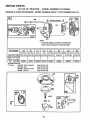
mance,
Should you experience any problem you cannot easily
remedy, please contact your nearest Sears Service
CentedDepartment.,
We have competent, well-trained
technicians and the proper tools to service or repair this
tractor.
Please read and retain this manual., The instructions will
enable you to assemble and maintain your tractor properly Always observe the "SAFETY RULES",
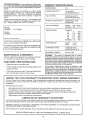
MODEL
NUMBER
917.,256930
HORSEPOWER:
125
GASOLINE CAPACITY:
1.,4 GALLONS
UNLEADED REGULAR
OIL (3..0 PINTS)
SAE 30 (above 32°F)
SAE 5W-30 (below 32°F)
SPARK PLUG (GAP 030 INn):
CHAMPION RJ_19LM
(STD361458)
VALVE CLEARANCE:
INTAKE:
EXHAUST:
_,005_ ,007 IN,,
,,009 - .,0! 1 IN,
GROUND SPEED:
FORWARD
1st
2rd
3th
4th
5th
REVERSE:
95
1,94
2,,9t
37I
4,76
1.46
TIRE PRESSURE:
FRONT:
REAR:
14 PSI
12 PSI
CHARGING SYSTEM:
3 AMPS BATTERY
5 AMPS HEADLIGHTS
BLADE BOLT TORQUE:
30-35 FT.,LBS,
SERIAL
NUMBER
DATE OF PURCHASE
THE MODELAND SERIAL NUMBERSWILL
ON A PLATE UNDER THE SEAT°
BE FOUND
YOU SHOULD RECORD BOTH SERIAL NUMBER AND
DATE OF PURCHASE AND KEEP IN A SAFE PLACE
FOR FUTURE REFERENCE,
MAINTENANCE
AGREEMENT
WARNING:
This tractor is equipped with an internal
combustion engine and should not be used on or near any
unimproved forest-covered, brush-covered or grass-covered land unless the engine's exhaust system is equipped
with a spark arrester meeting applicable loca! or state laws
(if any),, If a spark arrester is used, it should be maintained
in effective working order by the operator,,
A Sears maintenance agreement is available on this tractor, Contact your nearest Sears store for details°
CUSTO ER
RESPONSKB L T ES
o
Read and observe the safety rules,,
o
Follow a regular schedule in maintaining, caring for and
using your tractor°
"
Fol{owthe instructions under Customer Responsibilh
ties" and "Storage" sections of this manual,,
In the state of California the above is required by law
(Section 4442 of the California Public Resources Code).
Other states may have similar laws. Federal laws apply on
federal lands., A spark arrester for the muffler is available
through your nearest Sears authorized service center (See
the REPAIR PARTS section of this manual),
It
L MUTED TWO YEAR WARRANTY
MPH
MPH
MPH
MPH
MPH
MPH
ON ELECTRIC
START RRD NG EQUUPMENT
For two (2) years from the date of purchase, if this riding equipment is maintained, lubricated and tuned up according to the
instrdctions in the owneCs manual, Sears will repair or replace, free of charge, any parts found to be defective in material or
workmanship..
This Warranty does not cover:
,
o
•
•
Expendable items which become worn during normal use, such as blades, spark plugs, air cleaners and belts.
Tire replacement or repair caused by punctures from outside objects, such as nails, thorns, stumps, or glass..
Repairs necessary because of operator abuse, negligence, improper storage or accident or the failure to maintain the
equipment according to the instructions contained in the owner's manual.
Riding equipment used for commercial or rental purposes
90 DAY WARRANTY
ON BATTERY
For 90 days from date of purchase, if any battery included with this riding equipment proves defective in material or workmanship and our testing determines the battery will not hold a charge, Sears will replace the battery at no charge
WARRANTY SERVICE IS AVAILABLE BY RETURNING
CENTER!DEPARTMENT
IN THE UNITED STATES,,
THE RIDING EQUIPMENT
TO THE NEAREST
SEARS SERVICE
This Warranty gives you specific legal rights, and you may also have other rights which may vary from state to state
SEARS, ROEBUCK AND CO., D/817 WA, HOFFMAN ESTATES,
3
ILLINOIS
60179
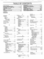
TA LE OF CONTENTS
SAFETY RULES ...... .............................................
.. ........ 2:.: ....
PRODUOT
SPECIFICATIONS
......................................
3
CUSTOM ER RESPONSIBILITIES
.....................
3, 15-18
WARRANTY
.................................................................
_3
TABLE OF CONTENTS
................................................
4
INDEX ............................................................................
4
TRACTOR
ACCESSORIES
..........................................
5
ASSEMBLY
..............................................................
7'-10
OPERATION ..........................................................
11-14
MAINTENANCE SCHEDULE ...... ,.... , ............. .;...,.".15
SERVICE AND ADJUSTMENTS ............................ 19-23
STORAGE ...................................................................
24
TROUBLESHOOTING
...........................................
25-26
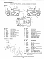
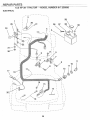
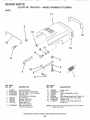
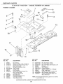
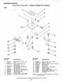
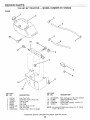
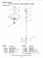
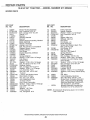
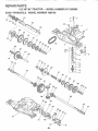
REPAIR PARTS - TRACTOR ................................ 30-47
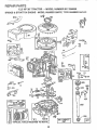
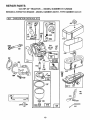
REPAIR PARTS - ENGINE ....................................
48-52
PARTS ORDERING/SERVICE
................... BACK PAGE
INDIEX
7
1
8
................................................
..................................................
.....................................................
A
E
Operation ..........................................................
11-14
Accessodes .................................................................
5
Electrical:
Operating Mower ................................................
13
Interlocks and Relays ...........................
23
Adjustments:
Options:
Schematic ....................................................
28
Brake ............................................................
21
Accessories _.:.............................................
5
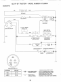
Wiring Diagram .......................................
30
Carburetor ...............................
:.................
23
Spark Arrester .....................................
3, 40
Mower:
Engine:
Front-T0:Back
...................................
20
Air Filter ............................................................
17
P
Side*To-Side .......................................
20
Air Filter Foam Pre-Cleaner ...........17
Parking
Brake
.............................................
11-12
Air Screen .................................................
18
Throttle Control Cable ...............................
23
Parts Bag ..............................................................
6
Cooling Fins, Engine .............................
18
Air Filter', Engine .............................................
17
Oil Change ......................................................
17
Parts, Replacement/Repair
..............30-47
Air Screen, Engine .......................................
18
Oi! Level .....................................................
13,17
Product Specifications .......................................
3
Assembly .........................................................
7-10
Oil Type .......................................................
17
Preparation ................................................
13
R
Repair Parts ..........................................
48-52
B
Repair
Pads
.......................................................
30-47
Starting ..............................................................
14
Battery:
Storage ........................................................
24
Charging ......................................................
8
S
Cleaning
F
Safety Rules ...............................................................
2
Installation
9
Filters:
Levels ...................................................
8,16
Seat ................................................................................
8
Air Filter ......................................................
17
Preparation
Service and Adjustments ..................19-23
Air Filter Foam Pre-Oleaner ...........17
Starling with Weak Battery ...........22
Brake .............................................................
21
Fuel ......................................................................
18
Storage ....................................................
24
Carburetor ....................................................
23
Terminals .............................................
17
Fuel:
Fuse .......................................................
22
Belt:
Hood Removal/installation
............22
Type ...................................................................
13
Motion Drive
Motion Ddve Belt
Storage .........................................................
24
Removal/Replacement
....................
21
Fuse ...........................................................................
22
Removal/Replacement
................
2t
Mower Installation ..............................
19
Blade:
Mower
Adjustment:
Sharpening ..............................................
16
H
Front- to-Back ....................................
20
Beplacement ................................... 16
Hood Removal/Installation
.........................
22
Side-to-Side
..........................................
20
Brake Adjustment .............................................
21
Mower Removal .....................................
tg
L
Tire Care .......................................
8,16,22
C
Carburetor Adjustment ..................................
23
Controfs, Tractor .............................................
11
Leveling Mower Deck ................................
20
Lubrication Chad ................................ 15
Slope Guide Sheet ....................................
55
Spark Plugs ............................................................
18
Specifications .........................................................
3
Start!rig the Engine ...............................
13q4
Steering Wheel ..............................................
7,21
................................................
Customer Responsibilities ..................
15-18
M
Engine:
Maintenance Schedule ...................................
15
Air Filter ...............................................
17
Mower:
Air Filter Foam Pre-Oleaner ..... 17
Stopping the Tractor. ......................................
12
Adjustment, Front-to-Back .............20
Air Screen, Engine .................... 18
Storage ..................................................................
24
:-:....... Adjustment;Side-to-Side...........
20 ...............
_.........
:............
........................
.......................
Battery'.,.,.,:.:,.:..:::.,..:;.:_::,.,:;_ 16-17
Blade Sharpening ...................................
16
Cooling Fins, Engine ......................
18
Blade Replacement ..............................
16
T
Engine Oil ..........................................
17
Fuel Filter ...............................................
18
Cutting Height .................................
12-13
Throttle Control Cable Adjustment .......23
Installation ...............................................
19
Tires ...................................................................
8,16,22
Spark Plugs ......................................
18
Tractor:
Operation ....................................................
13
Trouble Shooting Chart ........................
25-26
Remora ...............................
19
Blades
16
Transaxle
Repair
Parts
.........................
46-47
Lubrication Chart ..........................15
Mowing Tips .........................................................
14
Maintenance Schedule ................15
Muffler ...........................................................
!8
_V
Tire Care ................................
8,t6,22
Spark Arrester .......................... 3, 40
Cutting Height, Mower. .....................12-13
Warranty .............................................................
3
0
Oil:
Widng Diagram ................................................
30
Wiring Schematic ............................................
28
Cold Weather Conditions .........13,17
Engine ............................................................
17
Storage ..................................................................
24
4
.............
_!_:
i iii_iiiiii i i i i..i_iiii;iiii_i_iiii:.i_iiiii:,'
IH:,II':III.'--H----I--'
--I'T---_7:_""T'I"I
¸¸,i::_i:ii:!:ii::::!ii!!i!iii:i:ii:iiiiii,.:,=-,ii:;!i_iiilL"
=''::::_::',:'',:':'_::
:::_:'"_:_'.:""_'_=::=::=':'::
:':_'::"''_'_"_'_
:_L_;_:_:_L'_::::::¸ ::¸ /
.....
--H-I --
-.......................................
AOOESSORIE
AI D-AT"i'AOHI iI
TS.........
"......
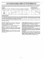
These accessories and attachments were available when the tractor was purchased. They are afso available at most,Sears retaii outlets,
catalog and service centers. Most Sears stores can order these items for you when you provide the model number of your tractor.
ENGINE
SPARK pLUG
[ViAINTENANCE
MUFFLER
AIR FILTER
GAS CAN
ENGINE OIL
STABILIZER
BLADES
BELTS
PERFORtVIANCE
Sears offers a wide variety of attachments that fit your tractor.
you. This list was current at the time of publication; however,
may be made in these attachments, or some may no longer
accessories
and attachments
that are available for your
Most of these attachments
attaching and detaching.
Many of these are listed below with brief explanations of how they can help
it may change in future years - more attachments may be added, changes
be available or fit your model, Contact your nearest Sears store for the
tractor,
do not require additional hitches or conversion kits (those that do are indicated)
and are designed for easy
PERMANEX
BAGGER lets you collect grass clippings and
leaves for a healthier, neater looking lawn. Two Permanex
containers hold 30-gal!on plastic bags.
CORING AERATOR takes small plugs out of soil to allow moisture and nutrients to reach grass roots. 36-inch swath. 24
hardened steel coring tips t50 lb. capacity weight tray°
LAWN SWEEPERS
AERATOR promotes deep root growth for a healthy lawn. Tapered 2oS-inch steel spikes mounted on 10-inch diameter discs
puncture holes in soil at close intervals to let moisture soak in.
Steel weight tray for increased penetration.
let you collect grass clippings and leaves..
CARTS make hauling easy. Variety of sizes available..
ROLLER for smoother tawn surface.
36-inch wide, 18-inch
diameterwater-tightdrumholdsupto390
Ibs. ofweighL Rounded
edges prevent harm to turf. Adjustable scraper automatically
cleans drum.
MULCH RAKE/DETHATCH
ER loosens soil and flips thatch and
matted leavesto lawn surface for easy pickup. Twenty spdngtine
teeth.. Useful toprepare bare areas for seeding. Available forrear
mounting only.
SPREADER/SEEDERS
make seeding, fertilizing, and weed
killing easy. Broadcast spreaders are also useful for granular
de-icers and sand..
SPRAYERS use 12-volt DC electric motor that connects to the
tractor battery or other 12-volt source.
Includes booms for
automatic spraying when pulling, and hand held wand for spot
spraying.
Wand has adjustable spray pattern.
For applying
herbicides, insecticides, fungicides, and liquid fertilizers
5
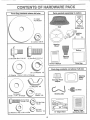
CONTENTS OF HARDWARE PACK
Parts Bag contents
shown
furl size
Parts packed
separately
in carton
(1) Large
Flat Washer
©
Seat
Battery acid
/ i_L _
(1) Locknut
Plate
3/8-24
Steering
Wheel
Battery
(1) ShouJder Bolt 5/16-18
Steering
Sleeve
(1) Hex Bolt 1/2-13 x 1
Owner's
blanual
Parts Bag
Parts bag contents
(1) Lock Washer
(1) Washer
not shown
full size
1/2
17_32 x 1-3/i6 x 12 Gauge
.......
,
,;;;;
...............
,,,
Steering Wheel
Adapter
©
Steering
Wheel
Insert
,,,
.....
(1) Wing Nut 3/8
(2) Keys
(1) Washer
13/32 x 1-1/4 x 16 Gauge
_+._
(1) Lock
_
Washer
Steering
Clip
3/8
I
1/4-20 x 3/4
(2) Hex Nuts
1
_1/4-20
I
_
(2) Washers
..................
(2) Lock
Washers
+++_............
1/4
15 ° Slope Sheet
9/32 x 5/8 x 16 Ga+
............
::
:
....
......
,,,
6
"_
Battery Caps
and Instructions
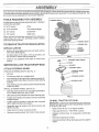
Your new tractor has been assembled at the factory with exception of those parts left unassembled for shipping purposes°
To ensure safe and proper operation of your tractor, alt parts and hardware you assemblemust be tightened securely, Use
the correct tools as necessaq7 to insure proper tightness_
TOOLS
REQUIRED
FOR ASSEMBLY
A socket wrench set wilt make assembly easier
wrench sizes are listed,,
STEERING
Standard
(1) 9/16" wrench
Pliers
(2) 7/16" wrenches
Tire pressure gauge
(1) 3/4" wrench
Screwdriver
(1) 1/2" wrench
Utility knife
When right and left hand are mentioned in this manual, it
means when you are in the operating position (seated
behind the steering wheel).,
TO REMOVE TRACTOR
UNPACK
CARTON
CARTON
o
Remove all accessible loose parts and parts cartons
from carton (See page 6)_
o
Cut along lines on the carton, from top to bottom, all
four corners of carton and lay panels flat..
o
ATTACH
STEERnNG
SHAFT
STEERING
CLiP
LOWER
STEERING
BUSHING
FIG. '1
Check for any additional loose parts or cartons and
remove..
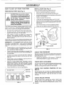
BEFORE ROLUNG
STEERING
_
STEERING
WHEELtNSERT
OCKNUT
TRACTOR OFF SKiD
WASHER
WHEEL
POSITION STEERING SHAFT (See Fig. t) o Lift hood
o
Pull steering shaft up to engage gears..
•
Push steering clip through hole on steering shaft at 45 °
(hole is located under dash and above lower steering
bushing),.
o
Push steering clip onto steering shaft until steering clip
snaps into place,,
INSTALL STEERING WHEEL (See Fig,, 2) o
Slide the steering sleeve over the steering shaft (Bottom of sleeve goes over ring on dash)
o
o
Slide steering wheel adapter onto upper steering shaft,
Position front wheels of the tractor so they are pointing
straight forward,
o
Position steering wheel so cross bars are horizontal
(left to right) and slide onto adapter°
•
Assemble large fiat washer and 3/8-24 focknut and
tighten securely°
o
Snap insert into center of steering wheel,
o
Remove protective plastic from tractor hood and grill.
FIG, 2
TO ROLL TRACTOR
OFF SKID
IMPORTANT: CHECK FOR AND REMOVE ANY STAPLES
IN SKID THAT MAY PUNCTURE TIRES WHERE TRACTOR
IS TO ROLL OFF SKID,.
o
Raise mower lift lever to its highest positiono
o
Place gearshift lever in "NEUTRAL"
o
Release parking
pedal,,
o
Roll tractor backwards off skid,
o
Remove banding holding discharge guard up against
tractor
position
brake by depressing
clutch/brake
ASS
LY
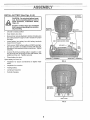
HOW TO SET UP YOUR TRACTOR
PREPARE
BATTERY
CAUTION:
_NSTALL
SEAT (See Fig. 4)
• ....
Adjust seat before tightening adjustment bolt,.
(See Fig. 3)
Wear eye and face shield.
Wash hands or clothing immediately if
accidentally in contact with battery acid.
Do not smoke.
Fumes from charged
battery acid are explosive.
Read the instructions included with the
battery vent caps. Always wear gloves,
clothing and goggles to protect your
hands, skin and eyes.
o
Remove cardboard packing on seat pan°
o
Place seat on pan and assemble shoulder bolt,.
=
Assemble adjustment bolt, !ockwasher and flat washer
!oosely. Do not tighten.
=
Tighten shoulder bolt securely.,
o
Lower seat into operating position and sit on seat,,
o
Slide seat until a comfortable position is reached which
allows you to press clutch/brake pedal all the way down
(See Fig. 8).
.
Get off seat without moving its adjusted position,
Raise seat and tighten adjustment
Your tractor has a battery charging system which is sufficient for normal use,. However; periodic charging of the
battery with an automotive charger will extend its life.
=
See instructions
=
Fill battery with aci& Fill each celt until it reaches the
bottom of the vent wells. Do not overfill.
bolt securely,.
SEAT
packed with vent caps in parts bag°
SEAT PAN
SHOULDER
BOLT
Allow battery to stand and settle for at least thirty
minutes. After standing, check the level of acid. If
below the vent wells, add more acid until the correct
level is reache&
While battery is standing (after adding acid) and later, while
battery is being charged, continue with assembly of tractor.
IMPORTANT:
TO MAXiMiZE THE LIFE OF YOUR
BATTERY, lT IS NECESSARY THAT THE BATTERY BE
CHARGED BEFORE USE,
FAILURE TO CHARGE
BATTERY CAN RESULT IN A SHORTENED BATTERY
LIFE
o
ADJUSTMENT
BOLT
Charge battery at a rate of 6 amperes for- 1 hour° Use
a 12 volt battery charger.. Observe all safety precautions required for battery charging_
°
Check the acid level after the battery is charged. If the
acid has fallen below the correct level, add distilled or'
iron free water,,
•
install the vent caps to cover the vent wells.. Wash the
top of the battery with water to remove any acid, then
wipe dry_
-
Check battery case for' leakage to make sure that no
damage has occurred in handling°
.
Dispose of excess battery acid_ Neutralize acid for
disposal by adding it to four inches of water in a five
gallon plastic container, Stir with a wooden or plastic
paddle while adding bakingsoda unti!the addition of
more soda causes no more foaming.
o
FLAT WASHER
FIG. 4
CHECK
=
Reduce tire pressure to PSI shown in "PRODUCT
SPECIFICATIONS" on page 3 of this manual.
CHECK
DECK
LEVELNESS
For best cutting results, mower' housing should be prope dy
leveled_ See "TO LEVEL MOWER HOUSING" in the ....
Service and Adjustments section of this manual.
CHECK
BELTS
VENT CAP
FOR
PROPER
POStT_ON
OF ALL
See the figures that are shown for replacing motion and
mower blade drive belts in the Service and Adjustments
section of this manual, Verify that the belts are routed
correctly..
VENT WELL
BATTERY
CELL ACID
LEVEL
FiG. 3
TIRE PRESSURE
The tires on your tractor were ovednflated at the factory for
shipping purpose& Correct tire pressure is important for
best cutting performance.
Follow instructions on how to install battery_
CUT AWAY VIEW
LOCK WASHER
CHECK
8
BRAKE
SYSTEM
After you learn how to operate your tractor, check to see
that the brake is properly adjusted. See "TO ADJUST
BRAKE" in the Service and Adjustments section of this
manual.,
INSTALL
BATTERY
(See Figs. 5 & 6)
BATTERY
BOX DOOR
CAUTION: Do not short battery terminals. Before installing battery, remove
metal bracelets,
wristwatch
bands,
rings, etc.
Positive terminal must be connected
first to prevent sparking from accidental grounding_
POSITIVE
(RED) CABLE
_EGATIVE
(BLACK) CABLE
Lift seat to raised position.
•
Open battery box door..
o
Be sure drain tube is attached to bottom of battery box
and tube passes through to hole in chassis for proper
drainage..
o
Lower battery into battery box with battery terminals
toward front of tractor_
First connect RED battery cable and RED fused igni_
tion wire to positive (+) battery terminal with hex bolt,
flat wastler, Iockwasher and hex nut as shown.. Tighten
securely°
o
Connect BLACK grounding cable to negative (-) battery terminal with remaining hex bolt, flat washer, lock
washer and hex nut,. Tighten securely..
.
Close battery box door°
POSITIVE
Open battery box door for:
o
Inspection for secure connections
ware)°
o
Inspection for corrosion°
o
Testing battery_
o
Jumping (if required)..
o
Periodic charging..
(+) TERMINAL
NEGATIVE
FIG. 5
(to tighten hard-
BOX DOOR
VENT CAPS
FIG. 6
9
(-) TERMINAL
ASSEM
LY
.............
iNSTALL
MULCHER
,
: :..:..:.....:..:
PLATE (See Figs. 7 & 8
DEFLECTOR
SHIELD
guard from mower. Raise and hold
guard when attaching
mulcher plate
and
allow it Do
to not
rest remove
on platedischarge
while in
CAUTION:
o,peratijon; ................
........
O
"""
WASHER
LOCK
WASHER
HANG
Raise and hold deflector shield in the upright position_
Position alignment cup over' rear baffle.
_)
Pivot mulcher plate forward and hook on mounting bolto
Be sure hang tab hooks top of deck opening..
Assemble fiat washer, lock washer' and wing nut to
mounting bolt and tighten securely..
3"0 CONVERT 3"0 BAGGING
DISCHARGRNG
OF{
WING NUT
MULCHER
PLATE
Simply remove mulcher plate and store in a safe place.
Your mower is now ready for discharging or installation of
optional grass catcher accessory.
FIG. 8
NOTE: If discharging or bagging results are unsatisfactory
with mulcher blades on mower, remove the mulcher blades
and install high performance discharging blades, which are
available at Retail and Catalog stores°
,/CHECKLIST
BEFORE YOU OPERATE AND ENJOY YOUR NEW
TRACTOR, WE WISH TO ASSURE THAT YOU RECEIVE
THE BEST PERFORMANCE AND SA TISFA CTION FROM
THIS QUALITY PRODUCT.
PLEASE REVIEW THE FOLLOWING
@
I_EFLECTOR
SHIEL
MOUNTING
BOLT
v"
All assembly instructions have been completed_
v"
No remaining loose parts in carton.
v"
Batteryis properly prepared and charged.
1 hour at 6 amps)_
v"
Seat is adjusted comfortably
v"
All tires are properly inflated. (For shipping purposes,
the tires were overinflated at the fa.ctory)
v"
Be sure mower deck is prdperly leveled side-to-side/
front-to-rear for best cutting results. (Tires must be
properly inflated for leveling).
Check mower and drive belts. Be sure they are routed
properly around pulleys and inside all belt keepers.
MULCHER
PLATE
@
v"
REAR
BAFFLE
ALIGNMENT
CUP
CHECKLIST:
FASTING
TAB SLOT
(Minimum
and tightened securely.
,/
Check wiring. See that all connections are still secure
and wires are properly clamped.
WHILE LEARNING HOW TO USE YOUR TRACTOR, PAY
EXTRA ATTENTION TO THE FOLLOWING IMPORTANT
ITEMS:
FIG. 7
,/
Engine oil is at proper' leveR..
7
Fuel tank is filled with fresh, clean, regular unleaded
gasoline_
Become familiar with all controls - their location and
function. Operate them before you start the engine_
¢"
,/
10
Be sure brake system is in safe operating condition.
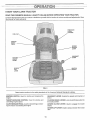
14:NOWYOUR
READ
THIS
LAWN TRACTOR
OWNER'S
MANUAL
& SAFETY
RULES
BEFORE
OPERATING
YOUR
TRACTOR.
Compare the illustrations with your tractor to familiarize yourself with the location of various controls and adjustments. Save
this manual for future reference.
THROTTLE/
CHOKE
CONTROL
FUEL CAP
CLUTCH/
BRAKE
PEDAL
"'"_
MOWER
CLUTCH
LEVER
GEARSHIFT
LEVER
PARKING
BRAKE
LEVER
MOWER
LIFT
LEVER
IGNITION
SWITCH
FIG. g
Sears tractors conform to the safety standards of the American National Standards _nstitute.,
IGNITION SWITCH:
engine.
Used for starting and stopping the
THROTTLE!CHOKE
CONTROL:
controlling engine speed,
GEARSHIFT
tractor,
LEVER: Selects the speed and direction of
Used for starting and
PARKING BRAKE LEVER: Locks clutch!brake pedal into
the brake position,
CLUTCHtBRAKE PEDAL: Used for declutching and braking the tractor and starting the engine_
MOWER CLUTCH LEVER: Used to engage the mower
blades,,
MOWER LIFT LEVER: Used to raise and lower the mower
deck,
11
OPERATION
The operation of any tractor can result in foreign objects thrown into the eyes, which can result
in severe eye damage, Always wear safety glasses or eye shields before starting your tractor
and while moving. We recommend wide vision safety mask for over the spectacles or standard
safety glasses.
HOW TO USE YOUR TRACTOR
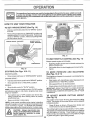
TO SET PARKING
BRAKE
(See Fig. 10)
o
Depress clutch/brake pedal into full "BRAKE" position
and hold
•
Place parking brake tever in "ENGAGED" position and
release pressure from clutch/brake pedal Pedal should
remain in "BRAKE" pos tion. Make sure park'ng brake
wilt hold tractor secure_
PARKING
CLUTCH/
BRAKE
PEDAL
THROTTLE/
CHOKE
CONTROL
GEARSHIFT
LEVER
PARKING
BRAKE
IGNITION
SWITCH
MOWER CLUTCH
LEVER "ENGAGED"
BRAKE"ENGAGED"
"DISENGAGED"
FIG. 11
TO USE THROTTLE
CLUTCHIBRAKE
PEDAL "BRAKE"
POSITION
(See FSg. 11)
Always operate engine at full throttle,.
"DISENGAGED"
FIG. 10
STOPPRNG (See Figs,
CONTROL
10 & 11)
=
Operating engine at less than full throttle reduces the
battery charging rate.
=
Full throttle offers the best bagging and mower performance,
TO
MOWER BLADES=
Move mower cfutch tever to "DISENGAGED"
MOVE
FORWARD
AND
BACKWARD
(See Figs. 10 & 11)
position.
The direction and speed of movement is controlled by the
gearshift lever.
o Start tractor with clutch/brake pedal depressed and
gearshift lever in "NEUTRAL" position.
GROUND DRIVE °
Depress ctutchtbrake pedal intofull "BRAKE" position,
•
Move gearshift lever to "NEUTRAL"
position,
o
ENGINE -
Move gearshift lever to desired position.
NOTE: Failure to move throttle control to "SLOW" position
and allowing engine to idle before stopping may cause
engine to "backfire",.
o
Slowly release clutch/brake pedal to start movement.
IMPORTANT: BRING TRACTOR TO A COMPLETE STOP
BEFORE SHIFTING OR CHANGING GEARS. FAILURE
TO DO SO WILL SHORTEN THE USEFUL LIFE OF YOUR
TRANSAXLE
o
Turn ignition key to "OFF" position and remove key.
Always remove key when leaving tractor to prevent
unauthorized use.
TO
Never use choke to stop engine,
The position of the mower lift lever determines the cutting
height. The position of the mowerlift lever can be adjusted
to desired position
°
Move throttle control to "SLOW" position,.
o
MOWER
CUTTRNG
HEIGHT
(See Fig. 12)
NOTE: Under certain conditions when tractor is standing
idle with the engine running, hot engine exhaust gases may
cause "browning" of grass, To eliminate this possibility,
always stop engine when stopping tractor on grass areas.
................
ADJUST
o
Grasp lift lever as shown, lift away from fender and
move forward or' back to desired position.
The cutting height range is approximately 1-1/8" to 3-5/8'L
The heights are measured from the ground to the blade tip
with the engine not running These heights are approximate and may vary depending upon soil conditions, height
of grass and types of grass being mowed
pletely, as described above, before leaving the operator's
position, to empty
grass catcher, etc.
12
o Theaveragelawn shouldbe cut to approximately
2-1/2inchesduringthe coolseasonandto over3
inchesduringhot months..For healthierandbetter
lookinglawns,mowoftenandaftermoderategrowth..
o Forbestcuttingperformance,
grassover6 inchesin
heightshouldbe mowedtwice. Makethe first cut
relativelyhigh;thesecondtodesiredheight..
o
Move gearshift lever to i st gear and be sure you have
allowed room for tractor to roll slightly as you restart
movement.
o
To restart movement, slowly release parking brake and
clutchlbrake pedal.
o
Make all turns slowly_
TO TRANSPORT
o
Raise mower lift lever to highest position
=
When pushing or towing your tractor, be sure gearshift
lever is in "NEUTRAL" position
o
Do not push tractor at more than five (5) MPH
NOTE: To protect hood from damage when transporting
your tractor on a truck or trailer, be sure hood is closed and
secured to tractor Use an appropriate means of tying hood
to tractor (rope, cord, etco)
BEFORE
CHECK
MOWER LIFT
LEVER
FIG. 12
TO OPERATE
MOWER
(See Figs.
°
Select desired height of cut..
o
Engage mower by slowly moving mowerclutch lever to
"ENGAGED" position..
TO STOP MOWER - Move mower clutch lever to
"DISENGAGED" position..
•
...........
,.......................
..
..............
...............
The engine in your tractor has been shipped from the
factory already filled with summer weight oil
o
Check engine oil with tractor on level ground
o
Remove oil fill dipstick and wipe clean, replace and
screw cap tight, wait for a few seconds, remove and
read oil level. If necessary, add oil until "FULL" mark
on dipstick is reached Do net overfill
o
For cold weather operation you should change oil for
easier starting (see "OIL VISCOSITY CHART" in the
Customer Responsibilities section of this manual)
o
To change engine oil, see the Customer Responsibilities section in this manual
Fit! fuel tank. Use fresh, clean, regular unleaded
gasoline. (Use of leaded gasoline will increase carbon
and lead oxide deposits and reduce valve life)
IMPORTANT: WHEN OPERATING IN TEMPERATURES
BELOW 32°F(0°C), USE FRESH, CLEAN WINTER GRADE
GASOLINE TO HELP INSURE GOOD COLD WEATHER
STARTING..
WARNING:
Experience indicates that afcotqol blended
fuels (called gasohol or using ethanol or methanol) can
attract moisture which leads to separation and formation of
acids during storage. Acidic gas can damage the fuel
system of an engine while in storage° To avoid engine
problems, the fuel system should be emptied before storage of 30 days or longer. Drain the gas tank, start the
engine and let it run until the fuel lines and carburetor are
empty. Use fresh fuel next season. See Storage Instructions for additional information.
Never use engine or
carburetor cleaner products in the fuel tank or permanent
damage may occur..
ON HDLLS
Choose the slowest speed before starting up or down
hilts.
o
Avoid stopping Or changing speed on hills..
o
If slowing is necessary, move throttle control lever to
slower position.
o
If stopping is absolutely necessary, push ctutchtbrake
pedal quickly to brake position and engage parking
brake.
(See Fig. 18)
o
,,, ,., ,_,,,
,
O5L LEVEL
ADD GASOUNE
CAUTION: Do not operate the mower
without either the entire grass catcher,
on mowers so equipped, or the discharge guard in place.
TO OPERATE
ENGINE
"['HE ENGHNE
o
10 & 12)
You r tractor is eq uipped with an operator presence sensing
switch. Any attempt by the operator to leave the seat with
the engine running and the mower clutch engaged wilt shut
off the engine
STARTING
i
13
filler neck. Do not overfill. Wipe off any
spilled oil or fuel. Do not store, spill or
CAUTION:
to bottom
gas tank
use gasoline Fillnear
an open of
flame.
TO START ENGBNE (See Fig. 9)
When starting engine for' the first time or if engine has run
out of fuel, it wilt take extra cranking time to move fue! from
the tank to the engine.
°
Depress the clutch/brake
brake.
pedal and set the parking
o
o
Place gearshift lever in "NEUTRAL" position.
Move mower clutch to*"DISENGAGED" position,.
.
Move throttle control lever to"CHOKE" position for cold
engine start.. For warm engine start, move throttle
control to "FAST" position..
o Turn ignition key clockwise to "START" position and
release key as soon as engine starts. Do not run
starter continuously for more than fifteen seconds per
minute. If engine does not start after several attempts,
move throttle control to "FAST" position, wait a few
minutes and try again,
o
When engine starts, move throttle control to desired
position.
°
Allow engine to warm up for a few minutes before
engaging drive or attachment clutch..
FIG, 13
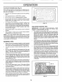
MULCHING
MOWHNG TBPS
itVlPORTANT:
FOR BEST PERFORMANCE,
KEEP
MOWER HOUSING FREE OF BUILT-UP GRASS AND
TRASH.. CLEAN AFTER EACH USE°
o
The special mulching blade will recut the grass clippings many times and reduce them in size so that as
they fall onto the lawn they will disperse into the grass
and not be noticed. Also, the mulched grass will
biodegrade quickly to provide nutrients for the lawn.
Always mulch with your highest engine (blade) speed
as this will provide the best recutting action of the
blades..
o
Mower should be properly leveled for best mowing
performance., See "TO LEVEL MOWER HOUSING" in
the Service and Adjustments section of this manual
The left hand side of mower should be used for trimming.
Avoid cutting your lawn when it is wet.. Wet gr ass tends
to form clumps and interferes with the mulching action.
The best time to mow your lawn is the early aftemoon_
At this time the grass has dried and the newly cut area
will not be exposed to the direct sun..
o
Drive so that clippings are discharged onto the area
that has been cut. Have the cut area to the right of the
tractor_ This wilt result in a more even distribution of
clippings and more uniform cutting,
For best results, adjust the mower cutting height so that
the mower cuts off only the top one-third of the grass
blades (See Fig. 14). For extremely heavy mulching,
reduce yourwidth of cut on each pass and mow slowly.
o
Certain types of grass and grass conditions may require that an area be mulched a second time to completely hide the clippings.. When doing a second cut,
mow across or perpendicular to the first cut path_
NOTE: if at a high altitude (above 3000 feet) or' in cold
temperatures (below 32 ° F), the carburetor fuel mixture
may need to be adjusted for best engine performance. See
"TO ADJUST CARBURETOR" in the Service and Adjust*
ments section of this manual.
MOWtNG
TRPS
When mowing large areas, start by turning to the right
so that clippings will discharge away from shrubs,
fences, driveways, etc.. After one or two rounds, mow
in the opposite direction making left hand turns until
finished (See Fig° 13)_
Change your cutting pattern from week to week. Mow
north to south one week then change to east to west the
next week. This witl help prevent matting and graining
of the lawno
If grass is extremely tall, it should be mowed twice to
reduce toad and possible fire hazard from dried clipdPings_Make first cut relatively high; the second to the
esired height;
..................................
.........................
MAX 113
Do not mow grass when it is wet, Wet grass will plug
mower and leave undesirable clumps. Allow grass to
dry before mowing..
Always operate engine at full throttle when mowing to
assure better mowing performance and proper discharge of material.. Regulate ground speed by selecting a low enough gear to give the mower cutting
performance as well as the quality of cut desired.
When operating attachments, select a ground speed
that will suit the terrain and give best performance of
the attachment being used.,
FIG. 14
14
....
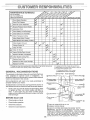
@l E-SP@N
AS YOU COMPLETE
7UES
..................
:::
.............
/_.55_,_9_
REGU_R
SERVICE
_[_0%_//
......
6!ES._
Check Brake Operation
64#
Check Tire Pressure
_#'
T
Checkfor Loose Fasteners
R
Sharpen/Replace Mower Blades
e/4
C Lubrication
Chart
T
0
Check Battery Level(Recharge
Clean Battery and Terminals
R
CheckTransaxle Cooling
Adjust Blade Belt(s) Tension
_/
....... .....................
..........
' .....'
Adjust Motion Drive Belt(s) Tension
Check Engine Oil Level
Change Engine Oi!
_4_
..............
i
_s
1¸
_'
_
.............._2.3
.C.leanAir Filter .......................
Clean Air Screen
_'2
_2
E
N
G Inspect Muffler!Spark Arrester
! Replace Oil Filler (If equipped)
C!ean Engine Cooli[i[i[i[[.Fi'i['i
...........
!_'
"[i."'.[.,
Replace Spark Plug
Replace Air Filter Paper Cartridge
Replace Fuel Filter
I - Change more often when operating under a heavy load or in high ambient
2 - Service more often when operating in didy or dusty conditions
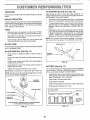
GENERAL
LUBRICATION
RECO_J_k'_ENDAT_ONS
Some adjustments will need to be made periodically
properly maintain your tractor..
Q
FRONT
Q
FRONT
BEARING
to
)NT SPINDLE
Once a year you should replace the spark plug, clean
or replace air filter, and check blades and belts for
wear.. A new spark pfug and clean air filter assure
proper air-fuel mixture and help your engine run better
and last longer.
USE
ENGINEQ
O
ATTACHMENT
CLUTCH PIVOT
O
CLUTCH
0
LIFT LEVER
/I
PIVOT
[_
THROTTLE
PLATE
PIVOT _
11
Check engine oil level.
o
Check brake operation,
o
Check tire pressure.,
O
SAE 30 OR t0W30
Check for loose fasteners,
Q
GENERAL
_'_
REFER TO CUSTOMER
15
O
ATTACHMENT
(_
CLUTCH LEVER
i
o
o
O
WHEEL Q
BEARING ZERI(
ZERK
PIVOT
All adjustments in the Service and Adjustments section of
this manual should be checked at least once each season_
EACH
Ct'_ART
®A×LE
P,VOT
HOOO
HINGES
®
The warranty on this tractor does not cover items that have
been subjected to operator abuse or negligence.. To
receive full value from the warranty, operator must maintain
tractor as instructed in this manual..
BEFORE
3 - It equipped with oil filter, change oil every 50 hours
4 * Replace btades mere often when mowing in sandy soil
5 - I1equipped with adjustable system
lemperalures
GEARSHIFT
PIVOTS
MOTOR
PURPOSE
O
OIL API _ SG
GREASE
RESPONSIBILITIES'ENGINE"
SECTION
IMPORTANT:
DO NOT OIL OR GREASE
THE PIVOT POINTS
WHICH HAVE SPECIAL
NYLON BEARINGS
VISCOUS LUBRICANTS WILL ATTRACT
DUST AND DIRT THAT WILL SHORTEN
THE LIFE OF THE SELF-LUBRICATING
BEARINGS.
IF YOU
FEEL THEY MUST BE LUBRICATED,
USE ONLY A DRY, POWDERED GRAPHITE
TYPE LUBRICANT
SPARINGLY
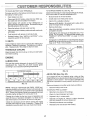
CUSTO
ESPONS
ER
TO SHARPEN
TRACTOR
Always observe
nance
BRAKE
OPERATION
TnRES
o
Maintain proper air pressure in afi tires (See "PRODUCT SPECIFICATIONS"
on page 3 of this manual).
o
Keep tires free of gasoline, oil, or insect control chemicals which can harm rubber..
o
Avoid stumps, stones, deel_ ruts, sharp objects and
other' hazards that may cause tire damage°
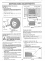
BLADE
(See Fig. 16)
Care should be taken to keep the blade balance&
An
unbalanced blade will cause excessive vibration and eventual damage to mower and engine.
safety rules when performing any mainte-
if tractor' requires more than six (6) feet stopping distance
at high speed in highest gear, then brake must be adjusted_
(See "TO ADJUST BRAKE" in the Service and Adjustments section of this manual).
BLADE
LINES
o
The blade can be sharpened with a rite or on a grinding
wheel° Do not attempt to sharpen while on the mower.,
o
To check blade balance, you wilt need a 5/8" diameter
steel boit, i_in,'oi-a c0ne balancer. (When using a cone
balancer, follow the instructions supplied with baF
ancer)o
o
Slide bladeon to an unthreaded portion of the steel bolt
or pin and hold the bolt or pin parallel with the ground.
If blade is balanced, it should remain in a horizontal
position.. If either end of the blade moves downward,
sharpen the heavy end until the blade is balanced.
NOTE: Do not use a nail for balancing blade.. The lobes of
the center hole may appear to be centered, but are not.,
CARE
CENTER
HOLE
/
/'
/
/
For best results mower blades must be kept sharp_ Replace
bent or damaged blades.
/'
/'
BLADE
BLADE REMOVAL
°
(See Fig. 15)
5/8"BOLT
OR PIN
Raise mower' to highest position to aliow access to
blades.
Remove hex bolt, lock washer and flat washer securing
blade.
o
o
Install new or resharpened
towards deck as shown_
blade with trailing edge up
FiG. 16
Reassemble hex bolt, lock washer and flat washer in
exact order' as shown..
BATTERY
°
Tighten bolt securely (30-35 Ft., Lbs. torque).
IMPORTANT: BLADE BOLT IS GRADE 8 HEAT TREATED.
Your unit has a battery charging system which is sufficient
for' normal use° However, periodic charging of the battery
with an automotive charger will extend its life..
NOTE: We do not recommend sharpening blade - but ifyou
do, be sure the blade is balanced°
BLADE
MANDREL
ASSEMBLY
TRAILING
(See Fig. 17)
EDGE
=
Acid solution level in each battery celt should be even
with bottoms of vent wells. Add only distilled oriron free
water if necessary. Do not overfill
o
Keep battery and terminals clean..
•
Keep battery bolts tight.
o
Keep vent caps tight and small vent holes in caps open.
=
Recharge at 6 amperes for' 1 hour.
CUT AWAY VIEW
•
_
.............................
_
HEX BOLT
(GRADE 8)*
VENT CAP
VENT
WELL
BATTERY
CELL ACID
LEVEL
*A GRADE 8 HEAT TREATED BOLT CAN BE IDENTIFIED
BY SIX LINES ON THE BOLT HEAD,
FIG. 17
FIG. 15
16
.....
.:
..........
•
TO CLEAN BATTERY AND TERMINALS
, .....
,,,
,,,,,, ,,, .......
1,,,,,,_ ,,: ....................
_" '"'_........
: ...........
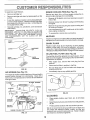
TO CHANGE ENGINE OIL (See Fig,, 18) -
-
Corrosion and dirt on the battery and terminals can cause
the battery to "leak" power,
Determine temperature range expected before oil change.
AI oil must meet API service classification SG
o
Open battery box door,,
o
Be sure tractor is on level surface,
o
Disconnect BLACK battery cable first then RED battery cable and remove battery from tractor.,
o
o
Oil will drain more freelywhen warm.
Catch oil in a suitable container.
o
Wash battery with solution of four tablespoons of
baking soda to one gallon of water. Be careful not to get
the soda solution into the cells,.
o
Remove oil fill dipstick., Be careful not to allow dirt to
enter the engine when changing oil,
o
Rinse the battery with plain water and dry
o
Remove drain plugo
o
Clean terminals and battery cable ends with wire brush
until brighL
o
After oil has drained completely,
and tighten securely,.
o
Coat terminals with grease or petroleum jelly,
o
o
Reinstall battery (See "INSTALL BATTERY"
Assembly section of this manual).,
Refill engine with oil through oil fill dipstick tube. Pout"
slowly, Do not overfill For approximate capacity see
"PRODUCT SPECIFICATIONS"
on page 3 of this
manual,
in the
Use gauge on oil fill dipstick for checking tevelo Be sure
dipstick cap is tightened securely for accurate reading.
Keep oil at "FULL" line on dipstick.
V- BELTS
Check V-Belts for deterioration and wear after 100 flours of
operation,, Replace if necessary. The belts are not adjustable,, Replace belts if they begin to slip from wear,•
TRANSAXLE
replace oil drain plug
OIL FILL
COOLING
Keep transaxle free from build-up of dirt and chaff which
can restrict cooling.
ENGINE
LUBRICATION
OIL
DRAIN
PLUG
Only use higl_ quality detergent ol rated with API service
classification SG. Select the oil's SAE viscosity grade
according to your expected operating temperature..
FIG, 19
SAE VISCOSITY GRADES
AiR FILTER
_F
"20_
°c -3oo
0"
30"
-='0'
TEMPERATURE
.1_"
32 _
40"
60_
0"
RANGE ANTICIPATED
fo,
BEFORE
BO"
_o'
Your engine will not run properly using a dirty air filter.
Clean the foam pre-cleaner element after every 25 hours of
operation or every season Service paper cartridge every
100 hours of operation or every season, whichever occurs
first,
100 °
_o°
(See Fig. 20)
no"
NEXT OIL CHANGE
FIG° '18
Service air cleaner more often under dusty conditions,
NOTE: Although multiviscosity oils (5W30, 10W30 etc)
improve starting in cold weather, these multi-viscosity oils
will result in increased oil consumption when used above
32°F. Check your engine oil level more frequently to avoid
possible engine damage from running tow on oilo
o
Remove knob(s) and cover,,
TO SERVICE PRE-CLEANER
-
o
Slide foam pre-cleaner off cartridge,.
o
Wash it in liquid detergent and water.
Change the oil after the first two hours of operation and
every 25 hours of operation thereafter or at least once a
year if the tractor is not used for 25 hours in one year,
°
o
Squeeze it dry in a clean cloth.
Saturate it in engine ol Wrap it in clean, absorbent
cloth and squeeze to remove excess oil,
Check the crankcase oil level before starting the engine
and after each eight (8) hours of operation. Tighten oil fill
cap/dipstick securely each time you check the oil level
o
Reinstall pre-cleaner over cartridge,
•
Reinstall cover and secure with knob(s).
17
OUSTO
TO SERVICE CARTRIDGE
ER
ESPO
-
ENGUNE COOLHNG F_NS (See Fig. 21}
•
Remove cartridge nuL
o
Remove cartridge and clean by tapping gently on ffat
surface..
o
If very dirty, replace orwash in a nonsudsing detergent
and warm water solution. Rinse thoroughly with water
from inside out until water runs clear'. Let cartridge dry
thoroughly before using,.
Remove any dust, dirt or oil from engine cooling fins to
prevent engine damage from overheating_
o
Reinstall cartridge, nut, precleaner, cover and secure
with knob(s).
IMPORTANT:
PETROLEUM
SOLVENTS, SUCH AS
KEROSENE, ARE NOT TO BE USED TO CLEAN THE
CARTRIDGE
THEY MAY CAUSE DETERIORATION OF
THE CARTRIDGE.. DO NOT OIL CARTRIDGE. DO NOT
USE PRESSURIZED
AIR TO CLEAN
OR DRY
CARTRIDGE.
°
Remove oil fill dipstick and cover opening to prevent
entry of dirt.
°
Remove screws from blower housing and lift housing
off engine.
°
Remove the screws securing the starter housing and
lift housing off engine
,
Use compressed air or stiff bristle brush to thoroughly
clean engine cooling fins.
•
To reassemble, reverse above procedure.
MUFFLER
Inspect and replace corroded muffler and spark arrester (if
equipped) as it could create a fire hazard and/or damage..
COVER
}(NOB "--'--
SPARK
COVER
PLUGS
Replace spark plugs at the beginning of each mowing
season or' after every 100 hours of operation, whichever
comes first. Spark plug type and gap setting are shown in
"PRODUCT SPECIFICATIONS" on page 3 of this manual.
CARTRIDGE
NUT
iN-MNE
FUEL FILTER
(See Fig. 22)
The fuel filter should be replaced once each season. If fuel
filter' becomes clogged, obstructing fuel flow to carburetor,
replacement is required.
PAPER
CARTRIDGE
FIG, 20
AiR SCREEN
ES
(See Fig. 21)
o
With engine cool, remove filter and plug fuel line
sections.
°
Place new fuel filter in position in fuel line,.
-
Be sure there are no fuel line leaks and clamps are
properly positioned_
o
Immediately wipe up any spilled gasoline,
The engine air screen must be kept free of dirt and chaff to
prevent engine damage from overheating. Clean with a
wire brush or compressed air to remove dirt and stubborn
dried gum fibers..
SCREWS
BLOWER
CLAMP
HOUSING
FUEL
FiG, 22
CLEANING
STARTER
HOUSING
SPARK
PLUG
OIL FILL
DIPSTICK
ENGINE COOLING
o
Clean engine, battery, seat, finish, etc. of all foreign
matter.
o
Keep finished surfaces and wheels free of all gasoline,
oil, etc_
o
Protect painted surfaces with automotive type wax.
We do not recommend using a garden hose to clean your
unit unless the electrical system, muffler, air filter and
carburetor are covered to keep water out.. Water in engine
can result in a shortened engine life,,
FINS
FIG. 21
18
CAUTION:
.
o
•
BEFORE PERFORMING ANY SERVICE OR ADJUSTMENTS:
Depress clutch/brake pedal fully and set parking brake.
Place gearshift lever in "NEUTRAL" position.
Place attachment clutch in "DISENGAGED
position.
Turn ignition key "OFF" and remove key.
Make sure the blades and all moving parts have completely stopped.
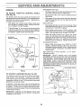
Disconnect spark plug wire from spark plug and place wire where it cannot come in contact with
plug.
°
°
.r
,, ..............
TRACTOR
TO REMOVE
MOWER
(See Figs. 23 & 24)
Mowerwill be easier'to remove from the right side of tractor,
o
Park tractor on a level surface and engage parking
brake..
°
Be sure that mower clutch lever is in "DISENGAGED"
position.
o
Move attachment
position,
•
Roll belt off engine pulley.,
o
Disconnect clutch rod from clutch arm by removing
retainer sp ring,
o
Disconnect rear suspension
removing retainer springs,.
o
Disconnect front links from mower deck by removing
retainer spring&
o
lift lever down to lowest cutting
MOWER LIFT LEVER
FIG, 23
arms from chassis by
CLUTCH
Disconnect rear lift links from mower deck by removing
retainer springs,
SPRING
REAR SUSPENSION
ARM (BOTH SIDES)
CAUTION: When rear lift links are removed, the lift arms will be pulled up to
the frame by the counterbalance spring.
Keep hands free when removing rear
lift links from lift arms.
°
°
RETAINER
CLUTCH
REAR LIFT LINK
(BOTH SIDES)
ENGINE
PULLEY
Raise mower lift lever to highest position,
Slide mower deck out on right side of tractor.,
TO INSTALL
MOWER
(See Figs. 23 & 24)
•
Move attachment lift lever up to its highest position.
•
Slide mowerdeck under tractor with discharge guard to
right side of tractor,.
,,
o
Move attachmentlift Ieverforwardto its lowest position..
Install mower deck in reverse order of removal instructions..
RETAINER
SPRINGS
RETAINER SPRINGS
(BOTH SIDES)
FIG. 24
19
SERVICE AND ADJUSTMENTS
TO LEVEL
MOWER
HOUSBNG
FRONT-TO-BACK
ADJUSTMENT
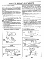
(See Figs. 27 & 28) IMPORTANT:
DECK MUST BE LEVEL S1DE*TO-SfDE.
IF
THE FOLLOWING
FRONT-TO-BACK
ADJUSTMENT
IS
NECESSARY,
BE SURE TO ADJUST BOTH FRONT LINKS
EQUALLY SO MOWER WILL STAY LEVEL SIDE-TO-SIDE
Adjust the mower while tractor is parked on level ground or
driveway.
Make sure tires are properly inflated (See
"PRODUCT SPECIFICATIONS" on page 3 of this manua0.
If tires are over o r underinfiated, you will not properly adjust
your mower'.
SiDE-TO-SIDE
ADJUSTMENT
To obtain the best cutting results, the mower' housing
should be adjusted so the front is approximately 1/4 to 3/4"
lower than the rear when the mower is in its highest
position.
(See Figs,. 25 and 26) -
.... You will need two (2) standard 2 x 4 short pieces of wood
to make the following adjustment, Similar blocks measuring t-I/2" thick may als0 be used,,
;
Raise mower with attachment lift control to allow two
(2) 1-1/2" thick blocks to be placed under rear edge of
mower deck,
o
Place one block directly behind right mandrel, Place
the remaining block under the stamped ridge on left
side of rear edge of mower deck
NOTE: Be sure blocks clear all hardware
exposed on underside of deck,
that may be
•
Lower' mower deck to its lowest height of cut position,
o
Loosen nut "C" so that the adjustment plate can move
up and down freely_
Be sure the mower deck rests level on both 1-I/2" thick
blocks, Retighten nut "C",
Raise mower with attachment lift control and remove
blocks from under' mower,
o
o
Check adjustment on right side of tractor. Measure distance "F" directly in front of and behind the mandrel at
bottom edge of mower housing as shown.
o
Before making any necessary adjustments, check that
both front links are equal in length
o
If links are not equal in length, adjust one lir_kto same
length as other link_
o
To lower front of mower housing, loosen nut "G" on
both front links an equal number of turns.
When distance "F" is 1/4" to 3/4" lower at front than
rear, tighten nut"H" against trunnion on both front links.
o
o
o
To raise front of mower housing, loosen nut "H" from
trunnion on both front links. Tighten nut "G" on both
front links an equal number of turns..
When distance "F" is 1/4" to 3/4" lower at front than
rear, tighten nut"H" against trunnion on both front links°
NOTE: Each full turn of nut "G" will change dim.. "F" by
approximately 3/8 inch.
PLACE TWO (2) 1-112" THICK BLOCKS UNDER REAR EDGE OF
DECK AS SHOWN (Usa wood 2 x 4's or equivalent)
o
Recheck side-to-side
REAR
adjustment,.
__ONT
,F,T_ROUND
t!/1/11/1//I//'tl/1///_/_/////f1_2_
f,=,
LINE
_
°
r
FIG. 27
BOTH FRONT LINKS SHOULD BE EQUAL IN LENGTH
NUT "H"
REAR
LIFT
LINK
REAR
SUSPENSION
ARM
ADJUSTMENT
PLATE
LINKS
RG. 26
20
FIG. 28
......
:-:-:-:
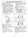
TO ADJUST
R.V
BRAKE
D:jU:ITIE-NTI
AID
(See Fig. 29)
Your tractor is equipped with an adjustable brake system
which is mounted on tile right side of the transaxle.
tf tractor requires more than six (6) feet stopping distance
at high speed in highest gear, then brake must be adjusted.
o
Depress clutch/Drake pedal and engage parking brake..
o
Measure distance between brake operatinga.rm
nut "A" on brake rod:
'
°
if distance is other than !-5f8", disengage parking
brake, loosen jam nut and turn nut "A" until distance
becomes 1-5/8"o Retighten jam nut against nut "A"..
o
Engage parking brake and recheck distance.,
=
Road test tractor for proper stopping distance as stated
above.. Readjust if necessary. If stopping distance is
still greater than six (6) feet in highest gear, further
maintenance is necessary..
Contact your nearest
authorized service center..
WITH PARKING
and _
o
Disconnect motion drive belt at chassis belt keeper.
o
o
Disconnect motion drive belt at engine pulley. Thread
belt below mower drive sheave and through engine belt
keeper and engine pulley,
Remove belt.
.
Install new belt by reversing above procedure,,
.
Make sure that belt is inside all belt keepers,
IMPORTANT: REPLACE ONLY WITH BELT LISTEDIN
THIS MANUAL,
MOTION DRIVE BELT
ENGINE
PULLEY
@
MOWER
DRIVE
SHEAVE
BRAKE "ENGAGED"
_)NUT
...........
:-.:::--::
MOWER DRIVE BELT
ENGINE
BELT
KEEPER
"A"
CLUTCH
PEDAL
SHAFT
CHASSIS
KEEPER
BELT
MOWER LIFT
SHAFT
TRANSAXLE
PULLEY
CLUTCHING
IDLER
FIG, 29
TO REPLACE
(See Fig. 30)
The tractor
the tractor
assistance,
side of left
MOTION
DRBVE BELT
FIG. 30
drive belt may be replaced without tools.. Park
on tevel area. Engage parking brake.. For
there is a belt installation guide decal on bottom
footrest.
TO ADJUST
STEERBNG
WHEEL
ALIGN[_ENT
If steering wheel crossbars are not horizontal (left to right)
when wheels are positioned straight forward, re move steering wheel and reassemble per instructions in the Assembly
section of this manual.
-
Engage parking brake
o
Lower mower lift lever to "lowest" position..
o
Turn front wheels fully to left or right..
o
Disconnect mower drive belt at engine puIley,
FRONT WHEEL
o
•
Disconnect motion drive belt at clutching idler.
Disconnect motion drive belt at transaxle. Push above
transaxle putley
The front wheel toe-in and camber are not adjustable on
your tractor, If damage has occurred to affect the front
wheel toe-in or camber, contact your nearest authorized
service center,
21
TOE-INtCA_'_BER
TO REMOVE
WHEEL
FOR REPAnRS
NEGATIVE
POSITIVE TERMINAL
(See Fig. 3!)
o
Block up axle securely.
o
Remove axle cover, retaining ring and washersto allow
wheel removal (rear wheel contains a square key - Do
not lose),
•
Repair tire and reassemble.
•
On rear wheels only: align grooves in rear wheel hub
and axle. Insert square key,
o
Replace washers and snap retaining ring securely in
axle groove..
o
Replace axle cover.
WASHERS
TERMINAL
CABLES
RETAINING
RING
CHARGED
BATTERY
POSITIVE TERMINAL
_
SQUARE
KEY
(REAR WHEEL ONLY)
WtfTH A WEAK
TO REPLACE
FUSE
Replace with 30 amp automotive-type plug-in fuse,. The
fuse holder is located next to the battery' box, accessible
from left rear wf_eel area.
FIG. 31
TO START ENGINE
See Fig, 32)
TERMINAL
FIGo 32
I
AXLE COVER
NEGATIVE
BATTERY
CAUTION: Lead-acid batteries generate explosive gases. Keep sparks, flame
and smoking materials away from batteries.
Always wear eye protection
when around batteries.
UNTERLOCKS
Loose or damaged wiring may cause your tractor to run
poorly, stop running or prevent it from starting.
o
Check wiring. See the electrical wiring diagram in the
Repai_ Parts section of this manual_
TO REMOVE
If your battery is too weak to start the engine, it should be
recharged..
If "jumper cables"
are used for' emergency
starting, follow this procedure:
IMPORTANT:
YOUR TRACTOR
IS EQUIPPED WITHA
12 VOLT NEGATIVE GROUNDED
SYSTEM. THE OTHER
VEHICLE
MUST
ALSO
BE A 12 VOL'T NEGATIVE
GROUNDEDSYSTEM.
DO NOTUSEYOURTRACTOR
BATTERY TO START OTHER VEHICLES..
AND RELAYS
HOOD
(See Fig.
33)
o
With hood closed,
brackeL
remove hood spring from pivot
o
=
Remove left side and right side pivot.
Lift hood off tractor..
o
To reassemble hood, reverse above procedure.
HOOD
SPRING
TO ATTACH JUMPER CABLES o Connect each end of the RED cable to the POSITIVE
(+) termina! of each battery, taking care not to short
against chassis,
o Connect one end of the BLACK cable to the NEGATIVE (-) terminal of fully charged battery°
o Connect the other end of the BLACK cable to a good
CHASSIS GROUND, away from fuel tank and battery_
\
TO REMOVE CABLES, REVERSE ORDER o
°
BLACK cable first from chassis and then from the fully
charged battery..
RED cable last from both batteries,
22
PIVOT
BRACKET
RIGHT SIDE PIVOT SCREW
FIG. 33
NTS.....................
:-..........
ENGBNE
PRELIMINARY SETTING -
TO ADJUST
THROTTLE
(See Fig. 34)
CONTROL
The throttle control has been preset at the factory and
adjustment should notbe necessary. Checkadjustment as
described below before loosening cable, If adjustment is
necessary, proceed as follows:
o
•
Aircleaner assembly must be assembled to the carburetor when making carburetor adjustments..
•
Be sure the throttle control cable is adjusted properly
(see above)°
°
With engine off turn idle mixture valve in (clockwise)
closing it finger tight and then turn out (counterclockwise) 1 full turn..
CABLE
FINAL SETTING -
With engine not running, move throttle control lever
from "SLOW" to "CHOKE" position° Slowly move lever
from "CHOKE" to "FAST" position..
•
Checkthathotes"A"
in governorcontrotfeverandhote
in governor ptate tine-up. If holes "A" are not aligned,
loosen clamp screw and move throttle cable until holes
are aligned. Tighten clamp screw securely.
Start engine and allow to warm for five minutes, Make
final adjustments with engine running and shift/motion
control lever in "NEUTRAL" position.
o
Move throttle control lever to "SLOW" position, With
finger, rotate and hold throttle lever against idle speed
screw,, Turn idle speed screw to attain 1750 RPM,
•
While still holding tflrottle lever against idle speed
screw, turn idle mixture valve in (clockwise) until engine begins to die and then turn out (counterclockwise)
until engine runs rough,. Turn valve to a point midway
between those two positions,, Release throttle lever.
o
GOVERNOR
CONTROL LEVER
GOVERNOR
CONTROL PLATE
ACCELERATION
o
\
High speed stop is factory
damage may result,,
"A"
CLAMP
SCREW
adjusted,.
THROTIFLE
CABLE
THROTTLE
CARBURETOR
(See Fig. 35)
The carburetor has been preset at the factory and adjustment should not be necessary. However, minor adjustment may be required to compensate for differences in fuel,
temperature, altitude or Ioad_ If the carburetor does need
adjustment, proceed as follows:
In general, turning idle mixture valve in (clockwise) decreases the supply of fuel to the engine giving a leaner fuel/
air mixture. Turning the idle mixture valve out (counterclockwise) increases the supply of fuel to the engine giving
a richer fuel/air mixture
IMPORTANT:
DAMAGE TO THE NEEDLE
THE SEAT tN CARBURETOR
MAY RESULT
TURNED 1N TOO TIGHT
Do not adjust
SPEED SCREW
LEVER,
{=IG. 34
TO ADJUST
"FAST"
mixture
test and
acceler-
IMPORTANT:
NEVER TAMPER
WITH THE ENGINE
GOVERNOR,
WHICH IS FACTORY
SET FOR PROPER
ENGINE SPEED,, OVERSPEEDING
THE ENGINE ABOVE
THE
FACTORY
HIGH
SPEED
SETTING
CAN
BE
DANGEROUS,
IF YOU THINK THE ENGfNE-GOVERNED
HIGH SPEED NEEDS ADJUSTING,
CONTACT
YOUR
NEAREST AUTHORIZED
SERVICE CENTER, WHICH HAS
PROPER EQUIPMENT AND EXPERIENCE
TO MAKE ANY
NECESSARY
ADJUSTMENTS,
/
HOLES
TEST -
Move throttle control lever from "SLOW" to
position°
If engine hesitates or dies, turn idle
valve out (counterclockwise)
1/8 turn. Repeat
continue to adjust, if necessary,
until engine
ates smoothly.
VALVE AND
IF SCREW 1S
IDLE MIXTURE
FIG, 35
23
VALVE
STORAGE
ENGINE
immediately prepare your tractor-for +storage at the end of
the season or if the tractor will not be used for 30 days or
more..
FUEL SYSTEPv_
IMPORTANT:
lT IS IMPORTANT
TO PREVENT
GUM
DEPOSITS
FROM
FORMING
IN ESSENTIAL
FUEL
SYSTEM PARTS SUCH AS CARBURETOR,
FUEL FILTER,
FUEL HOSE, OR TANK DURING
STORAGE.
ALSO,
EXPERIENCE
INDICATES
THAT ALCOHOL
BLENDED
FUELS (CALLED
GASOHOL
OR USING ETHANOL
OR
METHANOL)
CAN ATTRACT
MOISTURE
WHICH LEADS
TO SEPARATION
AND FORMATION
OF ACIDS DURING
STORAGE.
ACIDIC
GAS CAN DAMAGE
THE FUEL
SYSTEM OF AN ENGINE WHILE tN STORAGE.
gasoline in the tank inside a building
where fumes may reach an open flame
or
spark.
Allow store
the engine
to cool
CAUTION:
Never
the tractor
with
before storing in any enclosure.
I
.............
+,,
........
........
TRACTOR
Remove mower from tractor for winter' storage+ When
mower is to be stored for a period of time, clean it thoroughly, remove all dirt, grease, leaves, etc.. Store in a
clean, dry area.
•
Clean entire tractor (See"CLEAN1NG" in the Customer
Responsibilities section of this manual).
•
Inspect and replace belts, if necessary (See belt replacement instructions in the Service and Adjustments
section of this manual).
o
Lubricate as shown in the Customer Responsibilities
section of this manual.
o
Be sure that all nuts, bolts and screws are securely
fastened. Inspect moving parts fordarnage, breakage
and wear. Replace if necessary..
°
Touch up all rusted or chipped paint surfaces; sand
lightly before painting+
Fully charge the battery for storage.
=
After a period of time in storage, battery may require
recharging
-
To help prevent corrosion and power leakage during
long periods of storage, battery cables should be
disconnected and batten,/cleaned thoroughly (see"TO
CLEAN BATTERY AND TERMINALS" in the Customer Responsibilities section of this manual).
o
Start the engine and let it run until the fuel lines and
carburetor are empty+
o
Never use engine or carburetor cleaner products in the
fuel tank or permanent damage may occur.
Use fresh fuel next season..
NOTE: Fuel stabilizer' is an acceptable alternative in
minimizing the formation of fuel gum deposits during storage. Add stabilizer to gasoline in fuel tank or storage
container'. Always follow the mix ratio found on stabilizer
container. Run engine at least 10 minutes after adding
stabilizer to allow the stabilizer' to reach the carburetor. Do
not drain the gas tank and carburetor' if using fuel stabilizer,
ENGINE
OIL
Drain oil (with engine warm) and replace with clean engine
oil
(See "ENGINE" in the Customer Responsibilities
section of this manual)..
BATTERY
=
Drain the fuel tank..
o
CYLINDERS
After cleaning, leave cables disconnected and place
cables where they cannot come in contact with battery
teirninals_
o
Remove spark plug(s)..
°
Pour one ounce of oil through spark plug hole(s) into
cylinder(s)+
o
Turn ignition keyto"START"
to distribute oil..
o
Replace with new spark plug(s),.
position for a few seconds
OTHER
-
Be sure battery drain tube is securely attached,.
o
Do not store gasoline from one season to another:
-
if battery is removed from tractor for' storage, do not
store battery directly on concrete or damp surfaces.
°
Replace your gasoline can if your can starts to rusL
Rust and/or dirt in your gasoline will cause problems+
o
if possible, store your tractor indoors and cover it to
give protection from dust and dirt.
o
Cover your tractor with a suitable protective coyer'that
does not retain moisture.. Do net use plastic. Plastic
cannot breathe which albows condensation to form and
will cause your tractor to rust..
IMPORTANT: NEVER COVER TRACTOR WHILE ENGINE
AND EXHAUST AREAS ARE STILL WARM.
24
PROBLEM
CAUSE
Wit! not start
1
Out of fuel.
2
3.
4.
5.
6.
7
Engine not "CHOKED"
Engine flooded
Bad spark plug.
Dirty air filter.
Dirty fuel filter
Water tn fuel
8.
9.
10
Hard to start
1
Fill fuel tank.
properly
2
3
4
5
6
7
Loose or damaged wiring.
Carburetor out of adjustment
Engine valves out of adjustment
8
9
10
See "TO START ENGINE" in Operation section
Wait several minutes before attempting to start
Replace spark plug
Clean/replace air filter.
Replace fuel filter
Drain fuel tank and carburetor, refil tank with fresh
gasoline and repface fuel filer
Check all wiring
Contact an authorized service center/department..
Contact an authorized service center/department
1
2
Dirty air filer
Bad spark plug
3
4
5
6.
7.
8.
Engine wilt not turn over
Engine clicks
start
but will not
Loss of power
Weak or dead battery
Didy fuel filter
Stale or dirty fuel
Loose or damaged widng.
Carburetor out of adjustment
Engine valves out of adjustment
1
2,
3
4..
5..
6.
7.
8,
Clean/replace air filter
Replace spark plug
Recharge or replace battery
Replace fuel filter
Drain fuel tank and refill with fresh gasoline
Check atf wiring
Contact an authorized service center/depadment
Contact an authorized service center/department
1
2.
3.
4.
5.
6.
7.
8.
9
Clutchforake pedal not depressed
Attachment clutch is engaged
Weak or dead battery
Blown fuse
Corroded battery terminals
Loose or damaged wiring.
Faulty ignition switch.
Faulty solenoid or starter
Faulty operator presence switch(es).,
t
2
3.
4,,
5.
6.
7,
8.
9,
Depress clutchlbrake pedal.,
Disengage attachment clutch
Recharge or replace battery
Replace fuse
Clean battery terminals
Check al wiring.,
Check/replace ignition switch
Check/replace solenoid or starter
Contact an authorized service center/department
t
2
3
4
Weak or dead battery
Corroded battery terminals.
Loose or damaged wiring
Faulty solenoid or starter.
1
2
3
4,
Recharge or replace battery
Clean battery terminals
Check all wiring.
Checldreplace solenoid or starter
I
2.
3
4
5
6
7
8
9
Cutting too much grassltoo fast
Thmtte In "CHOKE" position
Build-up of grass, leaves and trash under mower
Dirty air filter
Low oil level/dirty oil
Faulty spark plug
Dirty fuel filer,,
Stale or dirty fuel
Water in fuel
1
2,
3
4
5
6
7
8.
9
Set in "Higher Cut" positiontreduce speed
Adjust throttle control
Clean underside of mower housing
Clean/replace air filter
Ci_eck oil level!change oil
Clean and regap or change spark plug.
Replace fuel filter
Drain fuel tank and refill with fresh gasoline
Drain fuel tank and carburetor, refill tank with fresh
gasoline and replace fuel filter,
Connect and lighten spark plug wire
Clean engine air screen/fins
Clean!replace muffler
Cileck all wiring
Contact an authorized service center/department
Contact an authorized service center/department
10
11
12
I3
14
!5
Excessive
vibration
CORRECTION
Spark plug wire loose..
Dirty engine air screerdfins
Dirty/clogged muffler
Loose or damaged wiring
Carburetor out of adjustment
Engine valves out of adjustment
1
2.
Worn, bent or loose blade
Bent blade mandrel..
3
Loose!damaged
10.
tl,
!2.
I3,
14
t5
1
2
3,
pad(s)
25
Replace blade,, Tighten blade bolt
Replace blade mandrel,
Tighten loose pad(s)
Replace damaged
pads
WFIOUIILESHOOWING POINWS
PROBLEM
CORRECTION
CAUSE
..................
Engine continues to run
when operator leaves seat
with attachment clutch
:,,,,, ,,,_,,,,.:,_,,
........
_:_
1..
Check widng, switches and connections
If not
corrected, contact an authodzed service center/
department
Worn, bent or loose bfade_
Mower deck not level.
Buildup of grass, leaves, and trash under mower,
Bent blade mandrel.
Clogged mower deck vent holes from butdup of
grass, leaves, and trash around mandrels.
t,
2
Replace blade.. Tighten blade bolt .
Level mower deck..
3
4*r
5.
Clean underside of mower housing
Replace blade mandrel,.
CEean aro_Jnd mandrels 1o open vent holes
Obstruction
t.
Faulty operator-safety
1..
2
3.
4,.
5
presence control system
engaged
Poorcut;uneven
Mower blades
rotate
1.
Remove obsiruction
4.
Worn!damaged mower drive belt
Frozen idler puley,.
Frozen blade mandrel
2.
3.
4.
Replace mower ddve belt.
Replace idler puley
Replace blade mandrel
t,
2.
3
4
Engine speed too slow
Travel speedtoo fast
Wet grass.
Mower deck not level,
t,.
2,
3
4.
Place throlle control in "FAST" position.
Shift to slower speed,
Allow grass to dry before mowing.
Level mower deck.
5.
6
Low/uneven tire air pressure.
Worn, bent or loose blade.
7.
8..
Buildup of grass, leaves and trash under mower
Mower drive bell worn
9.
10
11.
Blades improperly installed
improper blades used
Clogged mower deck vent ho_es from buildup of
grass, leaves, and trash around mandrels.
will not
2.
3,,
Poor grass discharge
Headight{s) not working
(if so equipped)
1 ,,
2
3
4
5
in clutch mechanism
Switch is "OFF",
Bulb(s) burned out,
Faulty light switch,
Loose or damaged wiring
Blown fuse
5,.
6.
7.
8.
9.
I0.
tt.
Check tires for proper air pressure..
Replace/sharpen btade Tighten blade bolt,
Clean underside of mower housing
Replace mower drive belt,
Reinstall blades sharp edge down,.
Replace with blades Isled tr_ this manual
Clean around mandrels to open vent holes
t.
Turn switch "ON"
2.
3.
4
5
Rel_lace bulb(s).
Chec]dreplace ight switch,.
Check wiring and connections.
Replace fuse
:: .., ...........
Battery wilt not charge
Engine "backfires"
when turning engtne
"OFF"
....
,,,, ......
, ....
1
2.
3.
4
Bad battery cell(s)
Poor cable conneclons.
Faulty regulator (if so equipped)
Faulty alternator
1,.
2,
Replace battery
Ctlecldclean all connections.
3
4
Replace regulator.
Replace alternator
1.
Engine throttle control not set at "SLOW"
position for 30 seconds before stopping engine,
t
Move throttle control to "SLOW" position and allow
to idle for 30 seconds before stopping engine
............
26
; .......
............... ;,,,
.....................
27'
12.5 HP 38" TRACTOR
° .-MODEL
NUMBER
917=256930
SCHEMATIC
°ill °
BATTERY
I ......
......
_
'
FUSE 3OAMP.
__
"
I
RED
Jl[
f,_2,
t
I
;
Jl
STARTER
WH!TE
1
SOLENOID
IGNITION
CLUTCH / BRAKE
(PEDAL UP)
SWITCH
t
I
t
t
I
1
SEAT SWITCH
(NOT OCCUPIED)
WHITE
1
I
t
{
I
|
............
I
BLACK
I
©,
BLACK
BLACK t"
J
ATT'M ENT CLUTCH
(CLUTCH OFF)
I
aLACK ._
GROUNDING
CONNECTOR
/37
@
)
BLACK
(_
IGNITION
UNIT
_
CHARGING
SYSTEM OUTPUT
3 AMP DC @ 36(}0 RPM
DIODE
SPARK
PLUG
_
28 VOLTS AC MtN. @ 3BO0 RPM
(CHARGING
SYSTEM DISCONNECTED)
It ..........
ALTERNATOR
__
M
F7-7
IGNITION SWITCH
POSITION
OFF
M+ G
ON
B+L
START
WIRING INSU[JkTED
CIRCUIT
B + S
NON-REMOVABLE
CONNECTIONS
REMOVABLE
CONNECTIONS
28
CLIPS
NOTE: IF WIRING INSULATED
CLIPS WERE REMOVED FOR
SERVICING OF UNIT, THEY
SHOULD BE REPLACED TO
PROPERLY SECURE YOUR WIRING
REPABR PARTS
12.5 HP 38" TRACTOR
=- MODEL
NUMBER
917.25693G
3
10
DECALS
17
8
11
\
4
6
15
\
12
16
2
13
14
KEY PART
NO. NO.
1
2
3
4
5
6
7
8
9
138272
127908
130OO1
138134
126241X
136332
133179
128314
132285
WNEELS
7
KEY PART
NO. NO.
DESCRIPTION
Decal,
Decal,
Decal,
Decal,
Decal,
Decal,
Decal,
Decal,
Decal,
10
11
!2
13
14
15
16
17
---
Instruction, Engine
Engine
Stripe, Hood, LH.
Stripe, Hood, R.H.
Grill
Side Panel
Mower QC System
Fender
Grill, USA
137537
133644
t23408X
135561
130929
133178
132928
132268
137659
137660
DESCRIPTION
Decal, Caution
Decal, Customer Maintenance
Decal, V-Belt Drive
Pad, Center
Decal, Mower Drive Schematic
Decal, Mower, 3 in 1
Decal, Deck Height Indicator
Decal, Steering Wheel Insert
Owner's Manual, English
Owner's Manual, Spanish
& TgRES
KEY PART
NO. NO.
1
2
3
4
5
5
59192
65139
278H
137422
132703
59904
8134H
6
9
7
7
8
9
t37237X311
1234t2X311
104757X
9040H
t21748X
DESCRPTION
Cap, Valve
Stem, Valve
Fitting, Grease (Front Only)
Tire, Front
Tire, Rear ....
_
Tube, Front Tire
(Not Supplied, Service Item Only)
Tube, Rear Tire
(Not Supplied, Service Item Only)
Rim, Front
Rim, Rear
Cap, Axle (Front and Rear)
Bearing, Flange (Front Only)
Washer 25/32 x 1-5/8 x 16 Gauge
NOTE: All component dimensions
1 inch = 2&4 mm
HARDWARE
SHOWN LARGER FOR EASIER IDENTIFICATION
29
given in U.S. inches
.........
:R.EPAmR,
PAR:'T$....................................................................................................
;_:_
...................
......................
..............................
.................
12.5 HP 38"TRACTOR
-= MODEL
NUMBER
917.256930
ELECTRICAL
29
24
2__
30
\
2t
I
f
\
2(
\
9
II
/
f
!
t
!
35
l
!
I
l
!
I
I
I
t
t
I
\ 1
\1 _
/
/
I
!1
it
t
3O
....................................
RF-PARR:PARTS................................................................................................
.................
...............
.................
.......................
...................
...............
,:i
_-_;'_
.....................................
12.5 HP 38" TRACTOR
KEY PART
NO, NO.
1
2
3
5
6
7
8
73510400
108423X
121265X
108236X
104445X
109553X
STD601005
9
10
I1
12
14
15
16
t7
18
19
20
21
22
23
24
25
26
27
28
29
30
35
36
I09310X
123620X
124211X
STD365402
7192J
121305X
STD54!431
108824X
128353
132223
73350400
STD551125
74780408
STD551225
t31563
138406
74760412
STD551025
STD551125
t2t264X
STD541025
11050600
11I50400
-- MODEL NUMIBER 917..2589-,3-0..................
DESCRIPTION
Nut, Hex, Keps 1/4-20 UNC
Assembly, Cable
Battery
Bracket, Switch
Switch, Interlock
Switch, Interlock
Screw, Hex Head, Tapping
#10-24 x 1/2
Key, Molded
Cover, Ignition Key
Nut, Ignition
Switch, Ignition
Tie, Cable
Switch, Plunger
Nut, Hex, Keps 5/16-18
Fuse
Assembly, Cable
Harness, Ignition
Nut, Hex, Jam !/4-20
Washer, Lock 1/4
Bolt, Hex Head 1/4-20 x 12 Grade 5
Washer, Loci<, ExternalTooth 1/4
Cover, Terminal
Solenoid
Bolt, Hex Head 1/4-20 UNC x 3/4
Washer 9/32 x 5/8 x 16 Gauge
Washer, Lock, Heavy Helical Spring 1/4
Cap, Batter!
Nut, Hex, Fin 1/4-20
Washer, Lock, External Tooth 3/8
Washer, Lock, Internal Tooth 1/4
NOTE: All component dimensions given in UoS,,incl3es
1 inch = 25.,4 mm
HARDWARE SHOWN LARGER FOR EASIER IDENTIFICATION
31
!
REPABR PARTS
12.5 HP 38" TRACTOR
-= MODEL
NUMBER
917.256930
HOOD
11
2
16
12
13
9
7
1
KEY PART
NO. NO.
1
2
3
4
124657X
STD541425
STD551025
STD522506
5
6
7
8
126675X
122549X
122548X
17411310
9
STD522507
KEY PART
NO. NO.
DESCRIPTUON
Spring, Extension
Nut, Hex; Keps 1/4-20 UNC
Washer 9/32 x 5/8 x 16 Gauge
Bolt, Hex, Fin.,
1/4-20 UNC x 5/8 Grade 5
Bolt, Shoulder
Bracket, Hood, RH
Bracket, Hood, LH
Screw, Hex, Fin.
#13-16 Hi-Lo x 5/8
Bolt, Hex Head, Fin°
1/4-20 x 3/4 Grade 5
HARDWARE
10
11
12
13
t6
17
18
19
123693X
132918X459
123706X
129970
124346X
STD551025
STD551031
11030400
DESCRIPTnON
Brace, Hood
Hood
Lens, Headlight Bar, Clear'
Grill
Nut, Washer Head, Self-Thread
Washer 9/32 x 3/4 x 16 Gauge
Washer 5/16
Washer, Lock, lnternal/Externa_
Tooth 1/4
NOTE: All component dimensions
1 inch = 25.4 mm
SHOWN LARGER FOR EASIER IDENTIFICATION
32
1/4
given in U.S. inches
12.5 HP 38" TRACTOR
FENDER
,.,,- NOD'EL NUMBER
917.256930
/ CHASSIS
7
1
18
3
12
5
i
20
23
17
16
!4
KEY PART
NO. NO.
1
2
3
129965
19132012
17490612
4
5
6
7
8
124t81X
I27t15X459
109596X
134214
17490512
9
10
I1
I2
13
139002
124602X
124346X
137097
109238X
KEY PART
NO. NO.
DESCRIPTION
Box, Battery
Washer 13/32 x 1-1/4 x 12 Gauge
Screw, Hex Washer Head, Thd.,
Rol!.. 3/8-16 x 3/4
Spring, Compression, Seat
Plate, Fender
Clamp, Hose
Pad, Footrest
Screw, Hex Washer Head, Thd.,
Roll.. 5/16-18 x 3/4
Console, Shift Control
Bar, Shift Lock
Nut, Self-Threading 3/16
Chassis Assembly
Tube, Battery Drain
14
15
16
I7
18
19
20
2i
22
23
25
STD54t425
STD541431
STD5231 O7
127880
126470X
132650X459
19091413
132562
17490508
STD533107
17490516
NOTE:
DESCRIPTION
Nut, Hex, Keps 1/4-20
Nut, Crownlock 5/16-18
Bolt, Hex Head 5/16-'18 UNC x 3/4
Drawbar
Clip, insulated
Fender/Footrest
Washer 9/32 x 7/8 x !3 Gauge
Plate, Depth Stop
Screw, Thd°, Roll. 5f16-18 x 1/2
Bolt, Carriage 5/16-18 x 3/4
Screw, Hex Washer Head, Thd,
Rollo 5/16-18 x 1
AII component dimensions
1 inch = 25°4 mm
HARDWARE SHOWN LARGER FOR EASIER IDENTIFICATION
33
given in U.S. inches
REPAHR PARTS
12.5 HP 38" TRACTOR
= = MODEL
NUMBER
917.256930
SEAT
5
6
7
f
8
22
17
]
14
13
KEY PART
NO. NO.
!
2
3
72050411
127436: ....
STD511005
4
5
6
7
8
9
10
11
12
STD541431
105529X
4171R
73951000
STD523707
126656X
126471X
19133210
STD541437
KEY PART
NO. NO.
DESCRIPTION
13 74780814
14-STD551150
15 19171912
16 127018X
t7
121251X
18 123976)(
19 121248X
20 12!250X
21 134300
22 121246X
23
131451
Bolt, Carriage 1/4-20 x 1-3/8
Seat ..........................
Screw, Slotted Pan Head
#10-32 x 1/2
Nut, Crownlock 5/16-18
Bolt, Shoulder 5/16-18 UNC
Clip, insulated
Nut, Hex, Keps #10-32 UNF
Bolt, Hex, Fin. 3/8-16 UNC x 3/4
Bracket, Pivot, Seat
Clip, Insulated
Washer 13/32 x 2 x 10 Gauge
Nut, Crownlock 3/8-16 UNC
NOTE:
DESCRPTDON
Bolt, Hex, Fin° 1/2-13 UNC x 1
Washer, Lock 1/2
Washer' 17/32 x 1-3/16 x 't2 Gauge
Bolt, Shoulder'
Strip, Foam
Locknut, Hex, Large, Flange
Bushing, Snap
Spring, Compression
Spacer', Split, Large _28 Id_ x _96
Bracket, Switch, Mounting
Pan, Seat
All component dimensions
1 inch = 25.4 mm
HARDWARE SHOWN LARGER FOR EASIER IDENTIFICATION
34
given in U.S° inches
......
.............
................................................................................................
•................
12.5 HP 38" TRACTOR
-- MODEL NUMBER
917.256930
DASH
I
8
17
18
21
KEY PART
NO. NO.
1
2
3
4
5
6
7
8
132734
138393
123487X
8544R
8548R
STD541425
2751R
STD551025
KEY PART
NO, NO.
DESCRIPTION
17
18
19
20
22
Cap, Fuel Tank
Assembly, Dash & Fuel Tank
Clamp, Hose
Line, Fuel
Line, Fuel
Nut, Hex, Keps 1/4-20
Clip, Fuel Line
Washer 9/32 x 3/4 x 16 Gauge
STD532505
131886
134744
1706O408
134O14
DESCRIPTION
Bolt, Carriage 1/4-20 x 1/2 Grade 5
Support Assembly, Dash
Brace, Gross
Screw, Self-Tapping 1/4-20 x 1/2
Plug, Dome
NOTE: All component dimensions
1 inch = 25,4 mm
HARDWARE SHOWN LARGER FOR EASIER IDENTIFICATION
35
given in US,, inches
REPAQRPARTS
12.5 HP 38" TRACTOR
° - MODEL
NUMBER
917.256930
7
KEY PART
NO. NO.
1
2
3
4
5
6
133742
STD541537
19133808
133741
121897X
STD6t1005
7
102803X
KEY PART
NO. NO.
DESCRIPTION
8
9
10
11
12
13
Insert, Steering Wheel
Locknut 3/8-24 UNF
Washer 13/32 x 2-3/8 x 8 Gauge
Steering Wheel
Sleeve, Steedng
Screw, Hex, Self-Tapping
#10-16 x 1/2
Bushing, Steering
123651X
124210X
123438X
12000045
STD551062
104820X
NOTE:
DESCRIPTION
Shaft, Steering
clip, Steering
Bushing, Lower, Steering
Ring, Retaining
Washer 21/32 x 1 x 16 Gauge
Adaptor, Steering Wheel
All component dimensions
1 inch = 2&4 turn
HARDWARE SHOWN LARGER FOR EASIER IDENTIFICATION
36
given in U.S_ inches
......
..............
REPAIR PA1RTS.................................................................................................
.......
.....................
............................
..............
12.5 HP 38" TRACTOR
SECTOR
GEAR 1 AXLE
= = MODEL
NUMBER
917.256930
SUPPORT
15
-
°,.,w-"
5
"4
4.,'%
[
'11
6
10 -----._..._
7
t
21
2O
,
KEY PART
NO. NO.
I
2
5
6
7
8
9
t0
1t
132566
74780828
121926X
121927X
730308O0
126472X
73680800
STD561210
STD551037
8
17
KEY PART
NO. NO.
DESCRIPTION
Link, Drag
Bolt, Hex Head, Fin. i/2-I3 x 1-3/4
Gear, Sector
Bushing
Nut, Heavy, Hex, Top Lock
1/2-13 UNC
Clip, Wire
Nut, Crownfock 1/2-13
Pin, Cotter 1t8 x 3/4
Washer 13132 x 13/16 x 16 Gauge
12
13
I4
i5
17
20
2I
126847X
STD523107
!9111416
STD533707
137096
STD541437
STD541431
DESCRBPTION
Bushing
Bolt, Hex Head 5/16-t8 UNC x 3/4
Washer 11/32 x 7/8 x 16 Gauge
Bolt, Carriage 3/8-16 UNC x 3/4
Support, Front Axle
Nut, Crownlock 3/8-16 UNC
Nut, Crownlock 5/16-!8
NOTE: All component dimensions
1 inch = 25.4 mm
HARDWARE SHOWN LARGER FOR EASIER IDENTIFICATION
37
given in U.S. inches
REPAmRPARTS
12.5 HP 38" TRACTOR
FRONT
° = MODEL
NUMBER
9!7.256930
AXLE
14
16
5
15
Jf
/
12
KEY PART
NO. NO....
1
2
3
4
5
6
7
8
9
10
!2t232X
12000029
121748X
3366R
133988
6266H
137062
121749X
STD56t210
STD551037
DESCRRPTION
KEY PART
NO_. NO.
............
Cap, Spindle
Ring, Klip
Washer 25/32 x t -5/8 x 16 Gauge
Bearing
Axle, Front
Bearing, Thrust
Spindle Assembly, R.H.
Washer 25/32 x 1-1/4 x 16 Gauge
Pin, Cotter 1/8 x 3/4
Washer 13/32 x 13/16 x 16 Gauge
HARDWARE
11
12
13
14
15
16
17
18
126847X
130465
137061
74011056
73901000
110438X
6855M
19272016
DESCRIPTION
Bushing
Rod, Tie
Spindle Assembly, L.H.
Bolt, Hex Head 518_1t x 3-1/2
Locknut, Flange 5/8-11
Bearing, Spacer
Fitting, Grease
Washer 27/32 x 1-1/4 x 16 Gauge
NOTE: All component dimensions
1 inch = 25..4 mm
SHOWN LARGER FOR EASIER iDENTIFICATION
38
given in U.S. inches
.................................
REPAaR PARTS ................................................................................................
12.5 HP 38" TRACTOR
BRAKE
/ REAR
MOWER
10
- - MODEL
NUMBER
917.256930
LIFT ASSEMBLY
1
4
2
5
6
9
10
28
12
8
11
KEY PART
NO. NO.
I
2
3
4
5
6
7
8
124236X
123436X
123437X
8883R
132205
STD560907
STD551037
t 7490508
9
10
I1
12
13
14
15
STD561210
STD551037
123543X
136263
123394X
121978X
123641X
KEY PART
NO. NO.
DESCRiPTiON
Cap, Plunger
Rod, Parking Brake
Bracket, Parking Brake
Cover, Pedal
Bracket Assy,, Clutch Pedal, L.H..
Pin, Cotter 3/32 x 3/4
Washer 13/32 x 5/8 x 16 Gauge
Screw, Hex Head, Thd, Roll:
5/t6-18 x 1/2
Pin, Cotter 1/8 x 3/4
Washer t 3/32 x 13/I 6 x 16 Gauge
Rod, Brake
Assembly, Clutch/Brake Pedal
Rod, Clutch
Bracket, Lift, Shaft
Assembly, Brake Pivot Arm
HARDWARE
16
I7
18
I9
20
21
25
27
28
29
30
31
32
19251816
12000034
106888X
STD541237
7368O6OO
131460
4497H
136780
136779
STD533107
STD541431
133095
133721
DESCRIPTION
Washer 25/32 x 1-1/8 x 16 Gauge
Ring, Klip
Spring, Brake Rod
Nut, Hex, ,Jam 3/8-16 UNC
Nut, Crownlock 3/8-16 UNC
Rod, Rear Brake
Spring, Retainer
Link, Threaded
Assembly, Rear Mower Lift
Bolt, Carriage 5/!6-18 UNC x 3/4
Nut, Hex, Keps 5/16-18 UNC
Spring, Counterbalance
Link, Lift Lever
NOTE: All component dimensions
1 inch = 25,4 mm
SHOWN LARGER FOR EASIER IDENTIFICATION
39
given in U.S. inches
REPAIR PARTS
12.5 HP 38" TRACTOR
ENGINE
-.. MODEL NUMBER
917.258930
/ THROTTLE
4
6
3
2
11
9
30
12
KEY PART
NO. NO.
1
17060408
2
3
132758
137418
4
71070512
5
STD551131
6
8
125593X
121094X
KEY PART
NO. NO.
DESCRIPTION
Screw, Hex Head, Thread Cutting
1/4-20 x 1/2
Control, Throttle
Engine, Briggs & Stratton, 125 HP,
Model #286707, Type #0441-01
Screw, Hex Cap Head
5/16-18 x 3/4
Washer, Lock, Heavy Helical Spring
5/16
Gasket, Exhaust
Bolt, Shoulder
HARDWARE
9
10
STD551031
STD551125
tl
12
15
t7
74760412
137437
137180
1749O624
18
126636X
DESCRIPTION
Washer' 5/16 x 3/4 x 16 Gauge
Washer, Lock, Heaw HeliCal Spring
1/4
Bolt, Hex, Fin, 1/4-20 UNC x 3/4
Muffler'
Kit, Spark Arrester (Optional)
Screw, Hex Washer Head, Thd°,
RoE 3/8-16 x 1-1/2
Keeper', Ground Drive Belt
NOTE:All component dimensions given in U,S. inches
1 inch = 25°4 mm
SHOWN LARGER FOR EASIER IDENTIFICATION
40
GROUND
DRIVE
4
0
18
2
,
KEY PART
NO. NO.
1
2
3
4
5
6
7
8
9
10
11
12
13
STD541431
STD523107
132946
I35036
STD551143
71130748
124525X
123405X
STD533715
123396X
123395X
4859J
STD551037
J14
DESCRIPTION
Nut, Crownlock 5/t6-18
Bolt, Hex Head 5/16-18 UNC x 3/4
Keeper, Mower Drive Belt, Engine
Pulley, Engine
Washer, Loci{ 7/16
Bolt, Hex, Fin, 7/I6_20 UNF x 3
Traction, V-Belt Drive
Keeper, T!A, Ground Drive Belt
Bolt, Carriage 3/8-16 x 1-1/2
Keeper, Ground Drive Belt, Idler
Clutch Arm, Ground Drive
Idler, Flat
Washer I3/32 x 13/16 x t6 Gauge
KEY PART
NO. NO.
DESCRIPTION
14
15
16
17
18
19
20
21
22
23
Nut, Centerlock 3/8-16 UNC
Nut, Crownlock 3/8-16 UNC
Clip, Insulated
Spacer, Retainer
Spring, Extension
Nut, Hex, Keps 5/16-18 UNC
Keeper, T/A, Ground Drive Belt
Washer 11/32 x 5/8 x 16 Gauge
Keeper, Chassis, Ground Drive Belt
Clip, Insulated
73930600
STD541437
t26471X
122052X
131459
STD541431
123891X
STD551025
123404X
126472X
NOTE: All component dimensions
I inch = 25.4 mm
HARDWARE SHOWN LARGER FOR EASIER IDENTIFICAT!ON
41
given in U.S, inches
REPAIR PARTS
12.5 HP 38" TRACTOR
- .- MODEL
NUMBER
917.256930
TRANSAXLEE
1
15 16
17
2O
I
I
3
4
\
28
11
10 31
KEY PART
NO. NO.
1
2
3
123385X
12000028
137365
4
5
6
7
8
2228M
STD54t431
STD533107
123378X
17490512
9
10
11
12
15
16
17
18
110422X
121749X
123583X
STD523727
STD551050
t24600X
t23632X
7104O412
KEY PART
NO. NO.
DESCRIPTaON
Pulley
Ring, Retainer
Transaxle, Dana, 5 Speed,
Model Number 4360-50
Key, Woodruff #9
Nut, Crownlock 5/16-18
Bolt, Carriage 5116-18 UNC x 3/4
Strap, Torque
Screw, Hex Head, Thd., Roll
5116-18 x 3/4
Spring, Brake
Washer' 25/32 x 1-1/4 x !6 Gauge
Key, Square
Bolt, Hex Head 3/8-16 x 2-3/4
Washer' !7/32 x I x i6 Gauge
Support, Shift Handle, Loll.
Link, Shift
Bolt, Hex Head, Fin.
1/4-28 x 3/4 Grade 8
HARDWARE
19
20
21
22
23
24
25
26
27
28
29
31
33
34
35
STD551125
19091210
123484X
105701X
130564
130714
STD561210-STD541531
STD541431
128085
128084
123409X
STD541437
11050500
STD581075
DESCRIPTBON
Washer, Lock 1/4
Washer 9/32 x 3/4 x 10 Gauge
Arm, Shift
Washer, Shift Plate
Knob
Rod, Shift
Pin; Cotter 1/8 x 1
Nut, Hex, Nylon 5/16-24
Nut, Hex, Keps 5/16-18
Spring, Extension
Support, Shift Handle, R.H.
Spacer
Nut, Crownlock 3/8-16
Washer, Lock, External Tooth 5/16
E-Ring
NOTE: All component dimensions
1 inch = 25,.4 rnm
SHOWN LARGER FOR EASIER IDENTIFICATION
42
given in U.So inches
PARTS:..........................................................................................
..................
=============
12.5 HP 38" TRACTOR
MOWER
- - MODEL NUMBER
917.256930
I
LIFT LEVER
123
12
-
2
/
10
13
"
,
5
l
35
""
I
/
27
31 ---'_
KEY PART
NO. NO,
1
2
3
4
5
6
7
8
t0
12
13
14
15
18
19
126470X
122018X
74780408
STD541437
132552
106451X
13511O
74930624
76020412
122027X
136658
133939
19131616
135107
73680400
4
22
7
DESCRiPTiON
Clip, Fuet Line
Bracket, Mower Clutch
Bolt, Hex Head, Fin,
1/4-20 UNC x I/2 Grade 5
Nut, Crownlock 3/8-16 UNC
Assembly, Clutch Lever
Bolt, Shoulder
Assembly, Mower Clutch Arm
Bolt, Hex Head 3/8-16 x 1-1/2
Pin, Cotter 1/8 x 3/4
Handle, Lift Lever
Assembly, Lift Handle
Spring, Compression, CIutch
Washer 13/32 x I x 16 Gauge
Trunnion
Nut, Crownlock 1/4-20
25
20
KEY PART
NO. NO.
DESCRIPTOON
2O
22
23
24
25
27
30
31
32
33
34
35
36
Bolt, Hex, Fin. 3/8-16 UNC x 2-3/4
Bracket, Lift Lever
Pin, Cotter 3/32 x 3/4
Washer 25164 x 1-1/4 x 12 Gauge
Tube, Spacer
Knob
Rod, Tension, Clutch
Nut, Centerlock 3/8-16
Spring, Extension, Return
Washer 13/32 x 2-3/8 x 8 Gauge
Nut, Crownlock 5/16-18
Cap, Vinyl, Red
Bolt, Carriage 5/16-18 x 3/4
STD523727
132561
76020312
7672J
121933X
121466X
135039
73930600
133435
62333
STD541431
133603
STD533107
NOTE: Ali component dimensions
1 inch = 25.4 mm
HARDWARE SHOWN LARGER FOR EASIER IDENTIFICATION
43
given in US.. inches
_EPAIF_ P_TS
MOWER DECK
12.5 HP 38" TRACTOR
" " MODEL
NUMBER
917.25893(}
31
32
35
63
/
/
37
/
24
I
27
23
3
6
69
7
68
65 616
67
3
16
12.5 HP 38" "TRACTOR ,- - MODEL
MOWER
DECK
KEY PART
NO. NO.
1
2
3
4
5
6
7
8
9
10
I1
12
13
14
I5
16
17
18
19
2O
21
22
23
24
25
26
27
28
29
30
31
32
33
34
35
36
37
38
39
40
41
NUI IBEIR 917.256930
138356
STD541431
STD533107
7631J
1t0485X
128774
129895
133172
134148
129962
STD551137
850857
128961
106736X
106735X
105896X
110452X
123713X
19111016
t05304X
128772
19111216
78158
STD624008
74600636
19131612
132556
733508O0
130171
STD541450
132553
STD541237
132559
133604
132554
STD551037
STD560907
133840
129963
129206
73050900
KEY PART
NO, NO.
DESCRIPTION
Mower Housing Assembly
Nut, Crownlock 5/16-t8
Bolt, Carriage 5/16-18 x 3f4
Runner, L°H..
Bearing
Housing, Mandrel
Bearing
Shaft & Bearing Assembly, Mandrel
Blade, Mulching
Washer, Hardened
Washer, Lock 3/8
Bolt, Hex 3/8-24 x '1-1/4 Grade 8
Stripper, Mower, Vented
Shield, Deflector
Rod, Hinge
Bracket Assembly, Deflector
Pushnut
Spring, Deflector
Washer 11/32 x 5!8 x 16 Gauge
Cap, Sleeve
Runner, RH.
Washer 11/32 x 3/4x 16 Gauge
Bolt, Hex Head 5116-18 x 1-1/4
Retainer, Spring
Bolt, Carriage 3/8-16 x 2-1/4
Washer 13/32 x 1 x 12 Gauge
Link Assembly, Front
Nut, Hex, Jam !/2-13 UNC
Trunnion
Locknut, with Washer Insert
Rod, Clutch, Primary
Nut, Hex, Jam .3/8-16
Arm, Suspension, Rear
Trunnion 3/8-16
Rod, Clutch, Secondary
Washer 13/32 x 13/16 x 16 Gauge
Pin, Cotter 3/32 x 3/4
idler Arm
Washer o150 Thick
Pulley, Mandrel
Nut, Ftangelock 9/16
42
43
44
45
46
47
48
49
50
51
52
131494
122052X
19131612
STD541437
131290
133502
133503
133551
131289
130840
'17490512
53
54
131288
STD533720
55
56
57
58
59
4921H
136782
72140606
19131212
73800500
60
61
62
63
64
65
66
19t1't112
72140506
3146R
4497H
73750600
19132016
10040600
67
68
69
--
135651
132803
74930620
138422
--
130794
DESCRIPTION
Pulley, Flat Idler
Spacer, Retainer
Washer 13/32 x ! x 12 Gauge
Nut, Crownlock 3/8-16
Belt
Spacer, Idler Arm
Stiffener, Idler Arm
Rod, Pivot
Rod, Brake, L.H.
Brake Assembly
Screw, Hex Washer Head, Thdo,
Roll.. 5t16-18 x 3/4
Rod, Brake, R.H
Bolt, Carriage
3/8-16 x 1-3/4 Grade 5
Spring, Retainer
Plate, Adjustment
Bolt, Carriage 3/8-16 x 3/4
Washer i3/32 x 3/4 x 12 Gauge
Locknut, Hex, with Washer Insert
5/16q 8 UNC
Washer 1'1/32 x 11/16 x 16 Gauge
Bolt, Carriage 5/16-18 X 3/4
Retainer Spring
Retainer Spring
Locknut 3/8-i6
Washer 13/32 x 1-1/4 x 16 Gauge
Washer, Lock, Heavy Helical Spring
3/8
Nut, Wing
Cover Assembly, Mulching
Bolt, Hex Head 3/8_16 x 1q/4
Mower Deck, Complete (Standard
Deck, Order Seperately Mulching
Blade and Mulching Components,
Key Numbers 9, and 64-69)
Mandrel Assembly (Includes Key
Numbers 5-8, t0-12, 39 and 41)
NOTE: All component dimensions
1 inch = 25,4 mm
HARDWARE SHOWN LARGER FOR EASIER IDENTIFICATION
45
given in U,S inches
REPABR PARTS
12_5 HP 38" TRACTOR
DANA TRANSAXLE
= MODEL
= ° MODEL
NUMBER
917.256930
NU_'_BER 4360=50
22
19
25
2
5i
32
26
33
27
34
30
36
i2
38
37
19
52
4O
53
41
42
54
47
55
56
57
59
56
I9
55
60
43 =
52
72
46
12.5 HP 38" TRACTOR
DANA TRANSAXLE
KEY PART
NO. NOo
!
2
138248
2274J
3
4
5
6
7
8
134400
105904X
105905X
138235
134399
106596X
9
10
11
12
13
14
!5
16
17
t8
t9
20
21
22
23
24
25
26
27
28
29
30
31
32
33
34
35
36
37
38
138241
2267J
134793
138240
120415X
2257J
138234
1t0078X
105909X
105910X
105911X
138242
138246
138236
134791
138243
2244J
105916X
120470X
110070X
108977X
134797
120405X
108980X
120406X
134796
105925X
2232J
108978X
110079X
39
124639X
= ' ODEL
° - MODEL NUMBER
NUMBER
917o256930
4360-50
KEY PART
NO. NO.
DESCRIPTION
Housing, Upper
Screw, Self-Tapping, Large
1/4-20 x .734
Ball, Detent
Spring, Detent
Screw, Set
Kit, Shifter Assembly
Boot, Shifter
Screw, Self-Tapping, Large
5/16-18 x 1..44
Square Ring
Ring, Retaining
Assembly, Kit, Shim .625 Shaft
Bearing, Flange
Washer, Plain ,.632 x 1.38 x °046
Key, Woodruff, #9
Assembly, Kit, Input Shaft
Pinion, Bevel, 14 Teeth
Ring, Retaining
Chain, 24 Pitches
Bearing, Flange
Gear, Spur, !4 Teeth
Collar, Clutch
Assembly, Kit, Clutch Keys
Screw, Self-Tapping, with Sealer
Shaft, intermediate
Key, Woodruff, #61
Ring, Retaining
Sprocket, 18 Teeth
Spacer
Gear, Spur, 37 Teeth
Spacer 1 _133 x 1.50 x °375
Gear, Spur, 30 Teeth
Gear, Spur, 25 Teeth
Gear, Spur, 22 Teeth
Gear, Spur, 19 Teeth
Washer, Plain ..640 x ! _.37x ..061
Washer, Plain 632 x 1.00 x .026
Spacer ..630 x 1.00 x .169
Assembly, Gear, Combination of
12 Teeth and 35 Teeth
Shaft, Idler
40
41
42
43
44
45
46
47
48
49
50
51
52
53
54
55
56
57
58
59
60
61
62
63
64
65
66
67
120472X
105928X
110084X
134394
t20473X
105933X
I05936X
t20407X
106589X
!20408X
105937X
2226J
134401
2264J
123907X
11008tX
105941X
110071X
t20952X
110082X
123908X
138247
120961X
7294J
108989X
I20953X
t20954X
134799
68
69
70
71
72
73
138244
108996X
120956X
738105OO
120951X
120416X
DESCRIPTION
Spacer .635 x °875 x .755
Sprocket, 9 Teeth
Gear, Bevel, 42 Teeth
* Assembly, Kit, Shim .750 Shaft
Shaft, Drive
Gear, Spur, 12 Teeth
Spacer ..781 x 1.00 x ..375
Gear, Spur, 20 Teeth
Gear, Spur, 25 Teeth
Gear, Spur, 28 Teeth
Gear, Spur, 31 Teeth
Washer, Plain .632 x 1o00 x ..060
Washer, Neoprene
Washer, Plain ..758 x 1_25 x 1031
Axle, L.H.
Gear, Miter, 15 Teeth
Ring, Retaining
Gear, Spur, 32 Teeth
Shaft, Cross
Gear, Miter, 15 Teeth
Axle, RH.
Housing, Lower
Puck, Friction
Disc, Brake
Spacer
Jaw, Brake
Pin, Dowel
Screw, Self-Tapping, Large
5/16-18 x 2.25
Lever, Actuating
Washer, Plain o32I x 1.00 x °055
Bracket, AntFRotation
Locknut 5/16-24
Puck, Friction
Grease
*
Use in combinations
**
Order Key No. 15
to maintain proper clearances
NOTE: All component dimensions
1 inch = 25.4 mm
47
given in US. inches
REPAUR PARTS
12.5 HP 38" TRACTOR
BRnGGS & STRATTON
..- MODEL
ENGUNE - MODEL NUMBER
NUMBER
917.256930
286707,
TYPE NUMBER
04.41-01
307
)
13
46
383
219
w
2Z
<3
*SPECIAL
TOOLS REQUIRED
TO INSTALL.
48
358 GASKETsET
!
REPAIR PARTS
12.5 HP 38" TRACTOR
BRIGGS
i 121
& STRATTON
CARBURETOR
- - MODEL
ENGINE - MODEL
OVERHAUL
NUMBER
NUMBER
286707,
917.256930
TYPE NUMBER
0441-01
KIT I
130
!
611
127
O
535
171
52
142
224
164
_
123
137
537
l
601 _
13B
49
84
REPAIR PARTS
12.5 HP 38" TRACTOR
BRIGGS
& STRATTON
- - MODEL NUMBER
ENGINE - MODEL NUMBER
iljjljj
917.256930
286707, TYPE NUMBER
0441-01
......
801
NOTE:
To Identlfy Brlggs and Stratton manufactured
starter motors, measure the housing length.
KEY NUMBER
309
Motor and
310
311
!ThruBolt
Brush
510
Drive
544
MANUFACTURER Drive Assy. !Assembly Assembly Assembly Assembly
Briggs & Housing
Stratton
12V
Length
3-21/32'
394805
*Includes Brush Set
**includes
#398003
#280104
#490467
#94288
94003
Clutch Assembly
Gear
Retainer and Pin
Roll Pin
395538
801
802
803
Armature Drive End Cap End Cap Assy.
490421**
890837
Assembly
Commutator
394856
395537*
Housing
Assembly
3981591
(Key Number 513)
(Key Number 783)
(Key Number 876)
(Key Number 898)
..............
_,lLJl'lll
668
1044
75
50
UI/ll
I
:
....
I'
REPAIR PARTS
12.5 HP 38" TRACTOR
BRIGGS
KEY PART
NO. NO.
1
2
490450
399265
3
5
7
8
9
10
tl
12
391086
494240
271866
391406
27803
94621
280100
271916
271997
271996
94622
94239
495162
94196
494238
291675
94624
492326
13
15
16
18
20
22
23
24
25
26
27
28
29
31
32
33
34
35
36
37
40
41
42
222698
394661
394662
394663
394664
391780
392331
391781
391782
391783
260924
299691
391286
490348
490469
222299
92909
262246
262247
65906
26828
224502
221596
292260
93630
& STRATTON
ENGINE
- - MODEL NUMBER 917,256930
- MODEL
NUMBER
286707, TYPE NUMBER
KEY PART
NO. NO.
DESCRIPTION
Cylinder Assembly
Bearing, Cylinder (Requires Special
Tools For Installation)
Seal, Oil
Head, Cylinder
Gasket, Cylinder Head
Breather Assembly
Gasket, Valve Cover
Screw, Seres
Tube, Breather
Gasket, Crankcase Cover 1/64"
Gasket, Crankcase Cover ..005"
Gasket, Crankcase Cover .009"
Screw, Cylinder Head 3"
Plug, Oil Drain
Crankshaft
Key, Timing Gear
Base, Engine
Seal, Oil
Screw, Sems, Base Mounting
Flywheel and Ring Gear Assembly,
Magneto
Key, Flywheel
Piston Assembly, Standard
Piston Assembly .010" Oversize
Piston Assembly .O20" Oversize
Piston Assembly .030" Oversize
Ring Set, Piston, Standard
Ring Set, Piston, Chrome, Standard
Ring Set, Piston .010" Oversize
Ring Set, Piston ,020" Oversize
Ring Set, Piston .030" Oversize
Lock, Piston Pin
Pin Assembly, Piston, Standard
Pin Assembly, Piston .005" Over
Rod Assembly, Connecting
Rod Assembly, Connecting
.020" Undersize Crankpin Bore
Lock, Connecting Rod Screw
Screw, Connecting Rod
Valve, Exhaust
Valve, Intake
Spring, Intake Valve
Spring, Exhaust Valve
Guard, Flywheel
Retainer, Intake Valve
Rotocoi!, Exhaust Valve
Retainer, Exhaust Valve Rotocoif
45
46
51
262248
212897
272465
52
272554
53
75
78
95
98
104
105
106
108
118
!21
94637
224061
93805
94098
495800
231789
231855
231854
224540
494383
495799
123
125
127
130
131
133
137
138
141
t42
94616
495706
147
164
171
187
188
201
209
216
2't 9
231794
213819
281051
393815
93535
262767
260871
262766
490815
224539
494379
494381
281165
281164
494380
494537
494499
0441-01
DESCRIPTION
Tappet*Valve
Gear, Cam
*** Gasket, Carburetor
(Carburetor to Etbow)
* Gasket, Carburetor
(Elbow to Cylinder)
Stud, Carburetor Mounting
Washer, Spring
Screw, Sems
** Screw, Throttle
Screw, Idle Speed
** Pin, Float Hinge
** Valve Assembly, Inlet Needle
Inlet Valve Seat
Valve, Choke
** Valve, Needle
Carburetor Overhaul Kit
(includes items marked ** and ***)
Screw, Elbow Mounting
Carburetor Assembly
** Plug, Welch (Sold in Kit Only)
Valve, Throttle
Shaft and Lever, Throttle
Float, Carburetor
*** Gasket, Float Bowl
*** Washer, Float Bowl Screw
** Shaft and Lever, Choke
** Nozzle/Jet, Carburetor
High Altitude Kit:
231796
Pilot Jet, High Altitude
281164
Seal, Bowl Screw
** Pilot, ,Jet
Carburetor, Elbow
Nut, Air Cleaner Mounting
Line, Fuel, 11" (Cut To Suit)
Screw, Sems 3/4"
Link, Governor
Spring, Governor
Link, Choke
Oil Slinger, Governor,Gear and
Bracket Assembly
* Included in Gasket Set (494241)
** Included in Carburetor Overhaul Kit (495799)
*** Included in both Carburetor Overhaul Kit (495799)
and Carburetor Gasket Set (494385)
NOTE:
51
All component dimensions
1 inch = 2&4 mm
given in U,,S_inches
REPAIR PARTS
12.5 HP 38" TRACTOR
BRIGGS
KEY PART
NO, NO.
222
494887
224
225
227
230
232
240
265
284
304
305
94729
231058
493935
94742
262785
394358
221535
94326
224504
94619
306
307
308
309
224545
94623
491490
---
333 492341
334 93381
337 802592
346 93705
356 494328
358 494241
363
383
422
423
445
455
467
468
474
482
523
524
525
535
537
552
562
592
601
611
614
615
19203
89838
224390
93984
493909
222561
493903
222562
393474
93621
495230
68838
280741
272403
281106
231597
92613
231082
93053
494451
93306
93307
& STRATTON
- - MODEL NUMBER
ENGINE - MODEL
NUMBER
286707,
KEY PART
NO. NO,
DESCRIPTION
Plate, Governor Control
(Choke-A-Matic)
Screw, Sem, Air Cleaner
Crank, Governor, 1/4" Diameter
Lever Assembly, Governor
Washer, Governer-Crank, 1/4" IoD_
Spring, Goyernor Link
Filter", Fuel
Clamp, Casing
Screw, Air Cleaner
Housing, Blower, Red
Screw, Seres, Blower Housing
Mounting
Shield, Cylinder
Screw, Seres, Cylinder Shield Mtgo
Coyer, Cylinder'Head
Motor, Starting, 12 Volt
(See Chart on lflustrated Pages
for Replacement Parts)
Armature, Magneto
Screw, Seres, Armature Mounting
Plug, Spark, (1-7/8" or' 47 mm)
(Resistor Type)
Screw, Hex Head
Wire, Ground
Gasket Set
(Includes ai_ items marked *)
Puller, Fiywheel
Wrench, Spark Plug
Clamp, Oil FillerTube
Screw, Serns
Cartridge, Air"Cleaner
Cup, Screen Mounting
Knob, Air Cleaner
Screen, Flush Rotating
Stator, Alternator, Dual Circuit
Screw, Sems
Cap and Dipstick, Oil Filler
Seal, Filler Tube
Tube, Oil Filler
Element, Air Cleaner
* O-Ring, Air Cleaner'
Bushing, Governor Crank, 1/4" LD.
Bolt, Governor Lever
Nut, Hex #10-24
Clamp, Fuel Pipe
Fuel Inlet Tube
Cotter', Hair Pin
Retainer, E_Ring
618
634
634A
634B
635
646
657
663
668
726
262803
281t68
491323
281167
66538
224546
93496
94620
280848
392134
727
490324
728
729
741
757
758
759
761
842
847
85t
869
870
871
872
875
877
94627
28t!59
262135
212359
399891
298909
93875
270920
490474
221798
261463
210940
261961
28t104
494237
393456
955 94642
965 94108
975 494378
977 494385
987 281166
1005 280687
1006 224413
1044 94673
RPM Settings:
917.256930
TYPE NUMBER
0441-01
DESCRIPTION
Spring, Choke Return
** Seal, Choke Shaft
* Seal, Governor
Washer, Throttle Shaft
Elbow, Spark Plug
Brace, Air Cleaner
Screw, Seres
Screw, Hex Head
Spacer
Gear, Ring
(Includes Mounting Parts)
Cover', Starter
(includes Mounting Screws)
Screw, Sems
Clip, Lead Wire
Gear, Timing
Link, Counterweight
Counterweight Assembly
Pin, Counterweight
Screw, Counterweight
Seal, Oil Filler Cap
Fill Group, Oil
Termina!, Ignition Cable
Seat, Intake Valve, Standard
Seat, Exhaust Valve, Standard
Guide, Exhaust Valve
Cover, Air Cleaner
Body, Air Cleaner
Diode and Connector Assembly,
Dual Circuit
** Screw, Fuel Bowl
Locknut, Air Cleaner Mounting
Bowl Assembly, Carburetor
Carburetor Gasket Kit
(Includes items marked ***)
** Seal, Threttte Shaft
Fan, Flywheel
Retainer, Fan
Screw, Shoulder, Hex Head
Low Speed: 1550-1950
High Speed: 3200-3400
* Included in Gasket Set (494241)
** Included in Carburetor Overhaul Kit (495799)
*** Included in both Carburetor' Overhaul Kit (495799)
and Carburetor Gasket Set (494385)
NOTE: All component dimensions given in U,So inches
1 inch = 25,,4 mm
52
ii
'
SERVICE NOTES
53
54
SUGGESTED
GUIDE FOR SiGHTiNG SLOPES FOR SAFE OPERATION
ONLY RIDE UP AND DOWN HILL,
NOT ACROSS HILL
SIGHTING
GUIDE
SIGHT AND HOLD THIS LEVEL WITH
SKY LINE OR TREE.
O'1
O1
15 ° MAX.
I!J /=_
! ,AA_
Iil _
t!i
Operate your Tractor up and down the face of slopes (not
greater than 15 ), never across the face. Make turns gradually to prevent tipping or loss of control. Exercise extreme
cau_,o.
_hen
chan_,._
_,reot!on
ono,o_e_
!
I
®
OWNER'S
MANUAL
12.5 HP
ELECTRIC START
3 in One Convertible
38" MOWER
5 SPEED TRANSAXLE
LAWN TRACTOR
Each tractor has its own model number,
its own model number.
MODEL NO.
917.256930
Each engine has
The model number for your tractor will be found on the
model plate located under the seat.
The model number for your engine will be found on the
blower housing of the engine.
All parts listed herein may be ordered from any Sears,
Roebuck and Co. Service Center?Department and most
Retail Stores.
WHEN ORDERING REPAIR PARTS, ALWAYS GIVE THE
FOLLOWING INFORMATION;
• PRODUCT-
HOW TO ORDER
REPAIR PARTS
LAWN TRACTOR
MODEL NUMBER - 917.256930
= ENGINE MODEL NO. - 286707_ TYPE NO. 0441-01
° PART NUMBER
• PART DESCRIPTION
Your Sears merchandise has added value when you
consider Sears has service units nationwide staffed with
Sears trained technicians.,,
professional
technicians
specifica!ly trained to insure that we meet our pledge to
you, we service what we sell.
137659
...........................................
Rev. 1
1o28,93
Printed in U.S.A,
.....
i.......
illl
i
i
...........