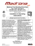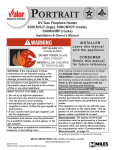
1
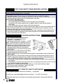
PORTRAIT DECORATIVE Models 922eCN/eCP Decorative Vented Gas Fireplace With Coal effect fuel Installation & Operating Instructions INSTALLER: Leave this manual with the appliance. CONSUMER: Retain this manual for future reference. Please read this manual BeFORe installing and operating this appliance. WARNING: If the information in these instructions is not followed exactly, a fire or explosion may result causing property damage, personal injury or loss of life. This appliance may be installed in an after-market permanently located, manufactured (mobile) home where not prohibited by local codes. Do not store or use gasoline or other flammable vapors and liquids in the vicinity of this or any other appliance. This appliance is only for use with the type of gas indicated on the rating plate. This appliance is not convertible for use with other gases, unless a certified kit is used. WHAT TO DO IF YOU SMeLL GAS • Do not try to light the appliance. • Do not touch any electrical switch; do not use any phone in your building. • Immediately call your gas supplier from a neighbor’s phone. Follow the gas supplier’s instructions. • If you cannot reach your gas supplier, call the fire department. Installation and service must be performed by a qualified installer, service agency or the gas supplier. This appliance is a domestic room-heating appliance. It must not be used for any other purposes such as drying clothes, etc. This appliance is suitable for installation in a bedroom or bed sitting room. Massachusetts: The piping and final gas connection must be performed by a licensed plumber or gas fitter in the State of Massachusetts. Ce guide d’installation est également offert en français. Manufactured by MILeS INDUSTRIeS LTD. 4000192-12 British Columbia, Canada www.valorfireplaces.com ©2011, Miles Industries Ltd. All rights reserved. Thank You ... For purchasing a Valor by Miles Industries. Your new radiant gas heater is a technical appliance that must be installed by a qualified dealer. Each Valor fireplace is fully tested during the production process for your safety and comfort. Your unit has been professionally installed by: Dealer Name _______________________________________ Phone Number ______________________________________ Should you encounter an operational problem, call your dealer immediately. Do not try to repair the unit as you may cause an injury or damage the fireplace. The information contained in this installation manual is believed to be correct at the time of printing. Miles Industries Ltd. reserves the right to change or modify any information or specifications without notice. Miles Industries Ltd. grants no warranty, implied or stated, for the installation or maintenance of your heater, and assumes no responsibility for any consequential damage(s). Fireplace Hearth We recommend that our gas hearth products be installed and serviced by professionals who are certified in the United States by NFI (National Fireplace Institute®). Do not put furniture or other objects in this space in front of the fireplace: 36” (0.9 m) Designed and Manufactured by Miles Industries Ltd. 190 – 2255 Dollarton Highway, North Vancouver, BC, CANADA V7H 3B1 Tel. 604-984-3496 Fax 604-984-0246 www.valorfireplaces.com © Copyright Miles Industries Ltd., 2011 2 Table of Contents ◊ Safety and Warning Information...............................................................4 ◊ Specifications.............................................................................................5 ◊ Options........................................................................................................6 Choice of Fronts.........................................................................................6 Location & Clearances...............................................................................7 Appliance Preparation...............................................................................8 Gas Supply Installation............................................................................10 Firebox Installation (insert application only).........................................11 Remote Control Installation.....................................................................12 Ceramic Fuel Bed Installation.................................................................13 923ACF Adorn Cast Front Installation....................................................15 Adorn Safety Guard Fitting......................................................................15 Operation Checks.....................................................................................16 Owner’s Information.................................................................................17 Lighting Instructions................................................................................18 Warranty....................................................................................................19 Replacement Parts...................................................................................20 ◊ = Updated content 3 Safety and Warning Information READ and UNDERSTAND all instructions carefully before starting the installation. FAILURE TO FOLLOW these installation instructions may result in possible fire hazard and will void the warranty. Prior to the first firing of the fireplace, READ the Owner’s Information section of this manual. DO NOT USE this appliance if any part has been under water. Immediately, CALL a qualified service technician to inspect the unit and to replace any part of the control system and any gas control that has been under water. THIS UNIT IS NOT FOR USE WITH SOLID FUEL. Installation and repair should be PERFORMED by a qualified service person. The appliance and venting system should be INSPECTED before initial use and at least annually by a professional service person. More frequent cleaning may be required due to excessive lint from carpeting, bedding, etc. It is IMPERATIVE that the unit’s control compartment, burner, and circulating air passageways BE KEPT CLEAN to provide for adequate combustion and ventilation air. Always KEEP the appliance clear and free from combustible materials, gasoline, and other flammable vapors and liquids. NEVER OBSTRUCT the flow of combustion and ventilation air. Keep the front of the appliance CLEAR of all obstacles and materials for servicing and proper operation. Due to the high temperature, the appliance should be LOCATED out of traffic areas and away from furniture and draperies. Clothing or flammable material SHOULD NOT BE PLACED on or near the appliance. This unit MUST be used with a vent system as described in this installation manual. NO OTHER vent system or components MAY BE USED. This gas fireplace and vent assembly MUST be vented directly to the outside and MUST NEVER be attached to a chimney serving a separate solid fuel burning appliance. Each gas appliance MUST USE a separate vent system. Common vent systems are PROHIBITED. INSPECT the external vent cap on a regular basis to make sure that no debris, plants, trees, shrubs are interfering with the air flow. Turn off the gas before servicing this appliance. It is recommended that a qualified service technician perform an appliance check-up at the beginning of each heating season. Any safety screen or guard removed for servicing must be replaced before operating this appliance. Children and adults should be ALERTED to the hazards of high surface temperature and should STAY AWAY to avoid burns or clothing ignition. Young children should be CAREFULLY SUPERVISED when they are in the same room as the appliance. Toddlers, young children and others may be susceptible to accidental contact burns. A physical barrier is recommended if there are at risk individuals in the house. To restrict access to a fireplace or stove, install an adjustable safety gate to keep toddlers, young children and other at risk individuals out of the room and away from hot surfaces. DO NOT place furniture or any other combustible household objects within 36” of the fireplace front. BE CAREFUL not to put any decorating objects sensitive to heat to close above or around the fireplace as it gets very hot when operating. DO NOT use this heater as a temporary source of heat during construction. 4 State of California. Proposition 65 Warning. Fuels used in gas, wood-burning or oil fired appliances, and the products of combustion of such fuels, contain chemicals known to the State of California to cause cancer, birth defects and other reproductive harm. California Health & Safety Code Sec. 25249.6. Safety and Warning Information Operating your fireplace for the first time. When operating your new fireplace for the first time, some vapors may be released due to the burning of curing compounds used in the manufacture of the appliance. They may cause a slight odor and could cause the flames to be the full height of the firebox, or even slightly higher, for the first few hours of operation. It is also possible that these vapors could set off any smoke detection alarms in the immediate vicinity. These vapors are quite normal on new appliances. We recommend opening a window to vent the room. After a few hours use, the vapors will have disappeared and the flames will be at their normal height. Specifications Approvals and Codes *High Altitude Installations This appliance is certified to ANSI Z21.50b–2009/CSA 2.22b–2009 Vented Gas Fireplaces Standard for use in Canada and USA. The appliance complies with CSA P4.1-09 Testing method for measuring annual fireplace efficiencies. The installation must conform with local codes or, in the absence of local codes with the National Fuel Gas Code, ANSI Z223.1or the Natural Gas and Propane Installation Code CAN/CGA-B149. Only qualified licensed or trained personnel should install the appliance. Input ratings are shown in BTU per hour and are certified without deration for elevations up to 4,500 feet (1,370 m) above sea level. For elevations above 4,500 feet (1,370 m) in USA, installations must be in accordance with the current ANSI Z223.1 and/or local codes having jurisdiction. Heating value of gas in some areas is reduced to compensate for elevation—consult your local gas utility to confirm. For installations at elevations above 4,500 feet (1,370 m) in Canada, please consult provincial and/or local authorities having jurisdiction. Venting This appliance must be connected to an approved venting system. Electrical Ratings Supply Gas Altitude (Ft) Input Max. (Btu/h) Input Min (Btu/h) Manifold pressure (in.w.c.) Min. Supply pressure (in. w.c.) Max. Supply pressure (in. w.c.) NG LPG 0-4500 * 20,500 19,000 12,000 12,500 3.7 10.5 5 11 10.5 13 The unit does not require an electrical power source. Model 922ECN is for use only with natural gas. Model 922ECP is for use only with propane gas. The supply pressure must be between the limits listed above. The supply connection is 3/8”NPT male thread. The supply pipe connection is to a flexible connector at the left hand side of the appliance. *Tested to CGA - 2.17-91 High Altitude Standard in Canada. In USA, installations may require deration over 2000’—Check local codes. 5 Options Fronts (required) 976BRK Bedroom Kit—Includes optional thermostat handset and wiring harness (for use in Canada only). 923ACF—Adorn Cast Front. 539 or 549 Cast Iron Arch Fronts—Also require #540WDK Wire Dress Guard, supplied separately. 3336 Closure Plate—For insert installations to cover up to 33” high x 36” wide. Other Accessories (optional) Hearth Gate (optional) 975ZCK Zero Clearance Kit—For installation into combustible type framing. Hearth gates such as Kidco’s are available at retail stores carrying safety products for children. Choice of Fronts 39” 31” 923 Adorn 539 Windsor Arch with Plate 34” 38” 30-1/4” 21-1/2” 549 Windsor Arch no Plate Note : the 539/549 Fronts require a 540 WDK Wire Dress Guard with the 922 heater. Standard black 33” high x 36” wide closure plate with black aluminum extrusion edge is available. Cast Iron Tolerances – Due to the nature of Cast Iron, dimensional consistency may vary from one unit to the next and some variation in surface finish and flatness is to be expected. We have done our best to control and make allowance, however some variation is inevitable. For installation instructions with Adorn cast front, see Adorn cast front installation section in this manual. Closure plates may be required for insert applications where cast fronts do not cover entire openings. For Windsor Arch cast fronts see instructions supplied with individual kit. 6 Location & Clearances before installation of the appliance. The liner must be a type approved by the enforcing authority and installed in accordance with the manufacturer’s instructions. This appliance must not be connected to a chimney flue serving a separate solid-fuel burning appliance. Note: The State of Massachusetts requires that any flue damper must be removed or permanently welded in the open position. The appliance must be installed on a floor, which is sufficiently flat and level to ensure stability. Some fireplace constructions have a well in the floor at the back that may need to be filled in. The appliance can be installed in the following constructions: Though not mandatory, we recommend that carpet, soft vinyl or other combustible floor coverings are kept at least 16” from the front of the appliance since these types of materials may be affected by the radiant heat output from this appliance. Solid-fuel (non-combustible) fireplaces As supplied, this appliance can be installed as an insert in an existing solid fuel type fireplace with a chimney and 4” dia. liner. The fireplace must be built in accordance with the national, state, provincial, or territorial building code recognised by the authority having jurisdiction, or in the absence of such a code, in accordance with the National Building Code of Canada or the National Fire Protection Association code in the USA. The size of the fireplace recess must be sufficient to accommodate the appliance as shown in figure below. The minimum clearances from any combustible constructions at the front of the appliance are shown below. The appliance must be connected to a vent that is a minimum of 9’-0” in height and must not have any 90 degrees elbows within 9’-0” of the flue outlet of the unit (see fig. below). Radiused offsets in the flue liner of less than 90 degrees are permitted. If previously used for burning solid-fuel, the chimney must be swept before installation of the appliance. Both chimney and fireplace must be checked for soundness Ceiling Min vent liner Ht 9’-0” Min Ht before 90 deg elbows is 9’-0”. Radiused offsets in liner are permitted Center line ceiling See mantel table B 36” min. to combust. mat’l 4-3/4” A Min. 39-1/2” Mantel depth A Edge of protruding arch Clearance from base of heater B 1” & 2” 3”-8” 40” 42-1/2” 7 Location & Clearances Enclosures Constructed Using Combustible Materials (ZC Installations) • Optional 975ZCK Zero Clearance Kit must be used when installing the 922 fireplace into any application other than as an insert into an approved solid-fuel burning fireplace cavity and chimney. Complete installation instructions are packed with the 975ZCK. • The 975ZCK is approved for installation directly on combustible type flooring such as plywood. Appliance Preparation Check ignition spark The pilot burner and electrode unit is at the left end of the burner. Push in the lighting knob and turn counter-clockwise through the “IGN” position to “PILOT”. A spark should flash across from the pilot electrode to the pilot burner shield. Aeration Setting Check The burner is equipped with an adjustable shutter to control primary aeration. See figure below. The shutter is factory set at an aeration gap which will give optimum performance for the vast majority of installations. In a few unusual installations, performance may be improved by adjusting the aeration. The need for adjustment should be determined by operating the appliance with the ceramic fuel effects and window installed. See the Final Checks section in this manual for adjustment details. The shutter setting is very critical. A small change can make a substantial difference to the performance. Air Shutters NG LPG Close Flashback shield (for LPG only) Open NG Air Shutter Slider & Cover 8 Close Open LPG Air Shutter Slider Close Open Appliance Preparation Install Base Coal Support Install base coal support (packed loose) to back of firebox using 3 screws as shown below. Remove Burner Module (optional) In some cases, to make gas piping easier, it may be convenient to remove the burner module from the firebox—note the location of the gas inlet before removing the burner module. Remove 2 screws and pull the burner module partially out of the firebox taking care not to pull on the wire leads going to vent switch. With the module partly removed, reach behind the module with a wrench and loosen the thermocouple nut at the back of the valve. With the thermocouple nut loose, pull the vent switch wire leads out of the brass block at the back of the valve and pull the burner module the rest of the way out of the firebox. Rough-in the gas line, valves, or unions and reinstall the burner module. 9 Gas Supply Installation • The appliance is supplied for supply gas connection at the left hand side of the case. There is also a gas line access at the rear of the firebox for insert applications. The zero clearance kit does not have access at the rear. Supply line connection to the flexible adapter is 3/8”NPT male thread. Alternatively, the appliance inlet pipe may be removed and the supply line routed directly to the control unit. An isolating valve could be fitted within the appliance case. • Use only new black iron or steel pipes or copper tubing if acceptable—check local codes. Note that in USA, copper tubing must be internally tinned for protection against sulfur compounds. • Ensure there is a pipe union (or flare fitting where permissible) ahead of the burner module for future servicing. Unions in gas lines should be of ground joint type. • The gas supply line must be sized and installed to provide a supply of gas sufficient to meet the maximum demand of the appliance without undue loss of pressure. • Sealant used must be resistant to the action of all gas constituents including LP gas. Sealant should be applied lightly to male threads to ensure excess sealant does not enter gas lines. • The supply line should include a manual shut-off valve to allow the appliance to be disconnected for servicing. • Pressure test the supply line for leaks. • The appliance and its individual shut-off valve must be disconnected from the gas supply piping system during any pressure testing of that system at test pressures in excess of 1/2 psig (3.5kPa). 10 • The appliance must be isolated from the gas supply piping system by closing its individual manual shutoff valve during any pressure testing of the gas supply piping system at test pressures equal to or less than 1/2 psig (3.5kPa). • Failure to either disconnect or isolate the appliance during pressure testing may result in regulator or valve damage. Consult your dealer in this case. • The minimum supply pressure is given in Specifications section of this manual. • All piping and connections must be tested for leaks after installation or servicing. All leaks must be corrected immediately. • When testing for leaks: • Make sure that the appliance is turned off. • Open the manual shut-off valve. • Test for leaks by applying a liquid detergent or soap solution to all joints. Bubbles forming indicate a gas leak. Never use an open flame to check for leaks. • Correct any leak detected immediately. • The pressure test tapping locations are shown here. A built-in regulator controls the burner manifold pressure. The correct pressure range is shown in the table in the Specifications section of this manual. The pressure check should be made with the burner alight and at its highest setting. See Lighting Instructions section for full operating details. Manifold pressure test tapping Supply pressure test tapping Firebox Installation (insert application only) Refer to 975ZCK installation manual for ZC firebox installation. To aid chimney liner connection, it may be necessary to first remove the vent collar connector from the top of the firebox—see figure below. 4. Insert a wall plug into each hole. 5. Secure the collar on the vent connector unit to the 4” diameter chimney liner. 6. Slide the firebox into the fireplace making sure that the vent connection unit is above the convection box. Leave the firebox front a few inches clear of the fireplace front to allow you to fix the vent connector to the top of the firebox. 7. With the vent connector started in the cleat pull the vent connector towards the front of the fireplace. Fix the front of the vent connector plate to the firebox front flange using the screw previously removed. 8. Push the convection box fully home against the front face of the fireplace. Make sure that no sags or dips occur in the liner. 9. Fit a woodscrew through each slot in the convection box base and tighten. 10.Re-install the burner module and connect the gas supply line to the module. 1. Remove the burner module from the firebox. 2. Insert the convection box into the fireplace opening feeding the supply pipe through hole at back or side of the firebox. 3. Mark the fireplace floor through the two slots in the base of the convection box (see figure below) and remove the convection box. Drill two holes in the fireplace floor at the marked positions using a no.12 masonry drill. 11 Remote Control Installation Caution! Do not fit the batteries into the remote control receiver until the wires are connected to the burner control unit, as a short circuit could result in the destruction of the electrical components. • Connect the wiring harness to the receiver box, by pushing the wire connector on to the receiver circuit board. The plug will only go on one way so, please ensure that the wires are pointing up and slot in the board is in line with the tab on the wiring harness plug. • Connect wires as shown below. Please note that the “L” connectors are different sizes, the smaller one fits to the lower connection on the valve. • Remove the remote control receiver lid. • Fit four 1.5V alkaline batteries. • Place the remote control receiver on the Velcro pad. • Fit the 9V alkaline battery to the handset transmitter. 12 Ceramic Fuel Bed Installation Ceramic Walls Installation 1. Locate the ceramic rear wall on top of the base coal support as shown. 2. Insert the right hand sidewall at an approximate 30-degree angle between the firebox side and the burner. Swing the top of the sidewall to the vertical position and locate behind the upper baffle—see figure below. 3. Repeat step 2 with left hand sidewall. 13 Ceramic Fuel Bed Installation Ceramic Coals Installation 1. Rest the base coal on the supports just behind the burner and let it rest against the base coal support at the back of the firebox. 2. Place the left front coal in position behind the metal lip at the front of the firebox. The side projection on this coal should be near the middle front of the firebox. 3. Place the right front coal behind the metal lip at the front of the firebox. Its left side should rest over the projection on the left front coal. 4. The center right coal has letter “R” embossed underneath. Place this coal behind the front right coal. 5. The center left coal has letter “L” embossed underneath. Place this coal behind the front left coal. 2 1 3 4 14 5 923ACF Adorn Cast Front Installation 1. Carefully lift the casting. Place it against the fireplace front surface so that the retaining strip at the back of the casting is above the two upper retaining brackets at the top of the convection box. 2. Lower the casting making sure that the rear retaining strip locates fully over the retaining brackets on the convection box—see figure below. 3. Slide the front casting/surround sideways, if necessary, to align the bottom fixing holes with those in the convection box. Fix the bottom of the casting/surround to the convection box with two screws—see figure below. Adorn Safety Guard Fitting 1. Locate the guard bottom wires over the ash lip. 2. Hold the top springs down and swing the guard back. 3. Release the springs so that they locate behind the canopy—see figures below. 15 Operation Checks Final Checks Check ignition, pilot stability, burner flames, and the full range of movement of the flame adjustment knob. See owner’s lighting instructions further on in this manual for full details. Aeration adjustment As described in manual, burner aeration is adjustable. For the vast majority of installations, no adjustment will be necessary. However, in a very few instances, performance may be improved by adjusting the aeration by sliding the shutter page 10. Evaluate the aeration only after the unit has warmed up – approximately 15 minutes. The shutter setting is very sensitive. Small adjustments can make a substantial difference to the flames Increasing aeration will cause the flame to appear more transparent and blue making the ceramic fuel effects glow more. Decreasing aeration will cause the flames to appear more yellow or orange making the fuel effects glow less. Too little aeration may result in black carbon forming and dropping into the firebox. Check venting efficiency A check for correct venting of combustion products must be made before the installed appliance is left with the customer. You will need a mirror for this check. The mirror must be cold and dry for the check so, keep in a cool place such as a freezer compartment while the fire is warming up. 1. Open the gas valve. 2. Light the appliance and set to high heat. Leave the appliance on for five minutes. 3. Make sure that the mirror is cold and dry. Place the mirror face downwards touching the bottom front of the black cross member and angled slightly upwards so that the mirror face can be seen. 4. The mirror face should remain clear for at least 5 seconds. 5. If condensation appears over the mirror face within 5 seconds, the venting is not functioning properly. Don’t allow the appliance to be used until the problem is cured. 16 Owner’s Information Warranty Card at the back of this manual. Please read the safety information on page 4 of this manual. Fireplace Hearth Do not put furniture or other objects in this space in front of the fireplace: 36” (0.9 m) Operating Your Fire The operating instructions are also on a chained plate inside the control access door. For your safety this appliance is fitted with a flame supervision device which will shut off the gas supply if, for any reason, the pilot flames go out. This device incorporates a fixed probe, which senses the heat from the pilot flame. If the probe is cool, the device will prevent any gas flow unless the burner control knob is kept pushed in at the PILOT position. See full lighting instructions on next page. Checks Performance of LPG appliances may be affected by the quality of commercial gas supplied in your area. A periodic check of the pilot and burner flames should be made. Check after the fire has been on for at least 30 minutes. The pilot flame must cover the tip of the thermocouple probe. The main burner flame pattern will vary from appliance to appliance depending on the type of installation and climatic conditions—see figures below. Thermocouple probe must be in flame The Valor Remote Control System Your Valor Remote Control helps you get the comfort, convenience and aesthetics you want from your Valor Gas Fireplace. Setting the Flame 1. Press either of the large “up” or “down” buttons. 2. To raise the flame, press and hold the “up” button until you come to the flame level you want. Let go. 3. To lower the flame, press and hold the down button until you come to the flame you want. Let go. 4. The flame level will remain just as you set it. When first turned on, the decorative flames will appear predominantly blue. After approximately 15 minutes, the flames will turn yellow. Cleaning Turn the fire off and allow it to cool before attempting any cleaning. Note that the fire will retain heat for some time after it has been turned off. Metal parts Clean the metal parts with a slightly damp cloth and then dry. Do not use abrasive cleaners, they could scratch the surface. Coals and ceramic firebox walls Dust etc. can be brushed from the coals using a soft bristle paintbrush after removing the safety guard. We suggest that you remove the coals in the reverse order to that shown in fitting instructions. Make sure that no particles are brushed into the ceramic burner slots. Correct Flame Appearance The appliance area must always be kept clear and free from combustible materials, gasoline and other flammable vapors and liquids. Inspect the vent terminal outdoors regularly to make sure there are no obstructions from birds nests, insects or rodents, trees, bushes, etc. Examine the whole vent system regularly. We recommend annually. Servicing All appliances use four 1.5V AA alkaline batteries for thermostat control. The batteries used in the remote control receiver are accessible by opening the bottom access panel and removing the lid of the remote control receiver. The handset has a 9V alkaline battery. General servicing If you require any attention to your appliance, contact your supplier quoting the model number. It will be helpful if the appliance serial number can also be quoted. This is on the rating plate, which is on a chained, plate accessible by opening the bottom access panel. 17 Lighting Instructions FOR YOUR SAFETY READ BEFORE LIGHTING WARNING: If you do not follow these instructions exactly, a fire or explosion may result causing property damage, personal injury or loss of life. A. This appliance has a pilot, which must be lighted by hand. When lighting the pilot, follow these instructions exactly. To save energy, turn the pilot off when not using the appliance. B. BEFORE LIGHTING smell all around the appliance area for gas. Be sure to smell next to the floor because some gas is heavier than air and will settle on the floor. WHAT TO DO IF YOU SMELL GAS • Do not try to light any appliance. • Do not touch any electric switch; do not use any phone in your building. • Immediately call your gas supplier from a neighbor’s phone. Follow the gas supplier’s instructions. • If you cannot reach your gas supplier, call the fire department. C. Use only your hand to push in or turn the control knobs. Never use tools. If the controls will not push in or turn by hand, don’t try to repair them, call a qualified service technician. Force or attempted repair may result in a fire or explosion. D. Do not use this appliance if any part has been under water. Immediately call a qualified service technician to inspect the appliance and to replace any part of the control system and any gas control, which has been under water. LIGHTING INSTRUCTIONS 1. STOP! Read the safety information above. 2. Set the flame adjustment knob as far clockwise as possible*. 3. Turn the gas control knob clockwise to OFF. NOTE: The knob cannot be turned from PILOT to OFF unless it is pushed in partially. Do not force. 4. Wait five (5) minutes to clear out any gas, then smell for gas, including near the floor. If you smell gas, STOP! Follow “B” in the safety information above. If you don’t smell gas, go to the next step. 5. Find the pilot. It is at the left side of the firebox viewed through slotted hole in front log. 6. Push in and turn the gas control knob counterclockwise until resistance is felt just before the “IGN” position. 7. Keep pushed in for a few seconds to allow gas to flow then, keeping knob depressed, turn to “PILOT” to light pilot. Hold knob in for a further 5 seconds then release. The knob should pop back out. Pilot should remain lit. If pilot goes out repeat steps 3 through 7. • If knob does not pop out when released, stop and immediately call your service technician or gas supplier. • If pilot lights but will not stay lit after several tries, turn the gas control knob to “OFF” and call your service technician or gas supplier. 8. When pilot is lit, partially depress the knob and turn to “ON” position (Burner alight). • Do not leave knob set between “PILOT” and “ON”. 9. Set the flame height to desired setting*. TO TURN OFF GAS TO APPLIANCE 1. Set the flame adjustment knob as far clockwise as possible* 2. Push in gas control knob slightly and turn clockwise to “OFF”. Do not force. * The flame height can be increased or decreased by depressing the remote control hand set 18 button. WA TY N A RR M GR A O PR T LOR OR If you have a problem with this unit, please contact your dealer or supplier immediately. Under no circumstances should you attempt to service the unit in any way by yourself. The warranties in paragraphs 1 and 2 are provided only to the first purchaser/user of this unit, are not transferable and are subject to the conditions and limitations in paragraphs 3, 4 and 5. Please review the conditions and limitations carefully and strictly follow their requirements. VA Warranty CO M F 1. Extended Warranty Coverage For a period of up to ten (10) years, Miles Industries Ltd., (the “Company”) or its appointed distributor will at its option pay the initial purchaser for the repair of, or will exchange the following parts or components which are found to be defective in material or workmanship under normal conditions of use and service: Part or Component Exterior steel casing Defect Covered Corrosion Maximum Warranty Period 10 years Glass Loss of structural integrity 10 years Cast iron parts Corrosion 10 years Firebox and heat exchanger Corrosion (but not discoloration) causing loss of structural integrity 10 years 2. Two-Year Parts Warranty In addition, for two (2) years from the date of purchase, the Company, at its option, can repair or exchange all parts and components not listed above but that are found to have a bona fide defect in material or workmanship under normal conditions of use. 3. Conditions and Limitations a) The warranty registration card must be completed by the initial owner and returned to the Company within 90 days of purchase. b) Installation and maintenance must be performed by an authorized and trained dealer in accordance with the Company’s installation instructions. c) This warranty is void where installation of the unit does not conform to all applicable codes including national and local gas appliance installation codes and building and fire codes. d) The owner must comply with all operating instructions. e) The Company is not responsible for the labor costs to remove defective parts or re-install repaired or replacement parts. f) The first purchaser or user of the unit will be responsible for any shipping charges for replacement parts as well as travel time incurred by the dealer to perform the warranty work. g) This warranty applies to non-commercial use and service and is void if it is apparent that there is abuse, misuse, alteration, improper installation, accident or lack of maintenance to the unit. h) This warranty does not cover damage to the unit through: i) Improper installation, operational or environmental conditions. ii) Inadequate ventilation in the area or competition for air from other household equipment or appliances. iii) Damage due to chemicals, dampness, condensation, or sulphur in the fuel supply lines which exceeds industry standards. i) This warranty does not cover glass, log breakage or damage to the unit while in transit. j) The Company does not allow anyone to extend, alter or modify this warranty and assumes no responsibility for direct, indirect or consequential damages caused by the unit. State or provincial laws where the first purchaser or user resides may provide specific rights to extend this warranty and, if so, the Company’s sole obligation under this warranty is to provide labor and/or materials in accordance with those laws. 4. Discharge of Liability After two (2) years from the date of purchase, the Company may, at its option, fully discharge all obligations under this warranty by paying to the first purchaser/user the wholesale price of any defective parts. 5. No Other Warranty All obligations to repair this unit are defined in this warranty. Some states or provinces may specifically mandate additional warranties on the part of manufacturers, but in the absence of such specific legislation, there is no other warranty or obligation expressed or implied. 19 Replacement Parts Code 1 2 3 4 5 6 7 8 9a 9b 10 11 12 13 14 15a 15b 16a 16b 16c 17a 17b 18 19 20 21 22 23 24 25a 25b 26 27 28 29 30 31 32 33a 33b 20 Description Drafthood retainer (2) Spigot slide plate assy Downdraft Top plate Mounting brkt Adorn x2 Switch plate Cable clamp Coal bed support Burner module NG Burner module LPG Remote control unit Wiring harness Remote handset Wall bracket Control box Burner rail assy NG Burner rail assy LPG Air shutter & slider LPG Air shutter slider NG Air shutter cover NG Injector elbow NG 82-580 Injector elbow LPG 92-200 Olive 8mm Olive nut Main burner pipe Spacer angle x2 Ash bed support x2 Module plate Pilot support bracket Pilot unit assy NG Pilot unit assy LPG Pilot bracket Electrode Thermocouple Extended nut Pilot pipe Tubing nut Pilot injector olive Pilot injector NG #35 Pilot injector LPG #27 Part. no. 4000166 4000199 4000359 4000332AH 4000348 4000360 4000361 4000413 4000230 4000164 030A217 720A556 720A555 N/A 720A554 3000025 740K185 4000268 / 3000220 4002345 4002346 720A580 9730013 420K342 220K567 030A225 4000355 330A894 4000297 330A904 4000062 4000063 720A542 720A543 4000061 720A200 030A226 420K385 720A196 4002511 720A195 Code 34 35 36 37 38 39 40 41 42 43 44 45 46 47 48 49 50 51 52 53 54 55 56 57 58 59 60 61 62 63 64 65 66 67 68 69 70 71 72 Description Part. no. Flexible pipe assy 4000345 Bypass screw LPG (incl. w 4003100S) Control valve GV34 4003100S Interruptor block 4000202 Vent switch assy 4000366 Break off olive nut 220K913 Straight connector (incl. w 4003100S) Valve mount bracket 4000275 Tube nut 420K385 Brick set 4000362 Brick panel left 4000358 Brick panel rear 4000356 Brick panel right 4000357 Coal set 000B245 Front right coal 640K618 Front left coal 640K617 Centre right coal 640K616 Centre left coal 640K615 Base coal 650K237 Dressguard - Adorn 450K023 Front casting 4000293AH Hearth trim casting 230K347 Crossmember 330A600 Top baffle 4000437 Floor heatshield 4000298AH Ash pan door assembly 040A481 Chrome plated knob 220K993 Grommet - foot 620B291 M5 screw 100D196 Ash pan cover painted 550K037AH Outer body 4000474 Vent adapter 4000473 Spacer 4000479 Heat baffle 4000478 Outer top panel 4000477 Inner top panel 4000476 Concrete board support 4000490 Inner body 4000475 Base 4000472 Replacement Parts 2 7 4 3 6 13 12 1 5 8 9a/b 11 10 14 922 BODY 15a/b 47 16b 16a 16c 24 17a/b 25A/B 49 26 21 27 22 18 23 19 28 29 33A/B 30 41 32 31 40 34 35 52 50 51 48 20 42 43 39 36 37 44 45 46 38 21 Replacement Parts 54 57 53 55 59 56 58 63 62 60 61 66 67 68 65 69 70 64 71 72 22 Thank You ... For purchasing a Valor by Miles Industries. Your new radiant gas heater is a technical appliance that must be installed by a qualified dealer. Please circle where appropriate - ask your installer or your dealer if in doubt. The information provided will be used for customer records only. Model: 922EC NG (natural gas) LPG (propane) Serial No: Front/Trim code/description (e.g. 549AFB Windsor Arch): Purchase date (mm-dd-yyyy): Home Owner Name: Address: City: Phone: ( Province/State: ) Postal Code/Zip: Email Address: Store Type: Fire shop Hardware Contractor Purchase Decision: Male Female Both Age: 30-39 40-49 50-59 60+ Friend Brochure Advertising Mailing Store New home Renovation Other Design Control Under 30 Other Heard of this product through: Internet Other Price Other Installation Type: Reason for Purchase: Performance Flame Appeal Previous owner Recommendation Dealer Name: Address: City: Phone: ( Province/State: Postal Code/Zip: ) Cut out page, fill information, and mail to Miles Industries Ltd. Online Warranty registration at www.valorfireplaces.com Tape Shut Fold here Postage needed Miles Industries Ltd. 190 - 2255 Dollarton Highway North Vancouver, BC V7H 3B1 Canada Online Warranty registration at www.valorfireplaces.com Were you given all documentation and manuals for your product? Thank you for choosing a Valor Product YES NO