1
Instruction Manual for
SphinxPro(SXP)
Equatorial Mount
PREFACE
Thank you for your purchase the Vixen SXP equatorial mount.
The SXP equatorial mount is a high precision sturdy mount ideal for astrophotography. The cutting-edge STAR BOOK TEN Hand Controller
feratures a high definision large color LCD screen with intuitive controls to help you enjoy your astronomical observation.
* The
manual describes the functions and uses of the SXP equatorial mount and vsrious Vixen Telescopes. You may occasionally find
descriptions not relevant to your model.
* Use this instruction manal in conjunction with your telescope manual.
* Features may be updated or new functions added.
Please visit Vixen's website for the latest software updates.
* Use the correct power source for the SXP equatorial mount or the optional AC Adapter sold separately.
Carefully read the instructions before use.
* Follow the instructions precisely.
* Keep this manual nearby to find quick answers to questions.
* This instruction manual will assist you in the safe use of the SXP equatorial mount.
WARNING!
Never look directly at the sun with your naked eyes or through your telescope and finder scope.
Permanent and irreversible eye damage may result.
* This equipment has been tested and found to comply with the limits for a Class B digital device, pursuant of Part 15 of the FCC rules.
CAUTION
* Do not try to restrain the movement of the mount when in operation, which may lead to injuries to you or damage to your equipment.
* Do not use the product in a wet environment.
* Do not turn on the power switch of the mount under circumstances when internal condensation is suspected on the equipment.
failure by a short circuit.
* Do not attempt to disassemble or alter any part of the equipment that is not expressly described in this manual.
result in electricasl shock or lead to injury.
* Do
It may cause a
This could damage the mount ,
not use the D-sub 9pin cable of the STAR BOOK TEN to connect to other equipment such as a PC. It may cause a failure, heating, or
electrical shock.
HANDLING and STORAGE
* Do not expose the product to rain, water drops, dirt or sand.
* When cleaning, do not use solvent such as paint thinners.
* For storage, keep the product in a dry place, and do not expose to direct sunlight.
* Remove the batteries from the battery compartment if the product is not used for a long time.
2
TABLE OF CONTENTS
Page
Chapter 5
PREFACE・・・・・・・・・・・・・・・・・・・・・・・・・・・・・・・・・・・・・・・・・・・・・・・・ P 2
APPLICATION ・・・・・・・・・・・・・・・・・・・・・・・・・・・・・・・・・・・・・・・・・・ P53
TABLE OF CONTENTS・・・・・・・・・・・・・・・・・・・・・・・・・・・・・・・・・・ P 3
I. How to Use the Polar Axis Scope ・・・・・・・・・・・・・・・・・・・・・・ P53
Polar Alignment・・・・・・・・・・・・・・・・・・・・・・・・・・・・・・・・・・・・・・ P53
Precise Polar Alignment・・・・・・・・・・・・・・・・・・・・・・・・・・・・・・ P58
Change the Altitude Setting on the SXP Mount ・・・・・・・ P59
II. Initial Configuration ・・・・・・・・・・・・・・・・・・・・・・・・・・・・・・・・・・・・ P60
Use Last Mount Setting・
・・・・・・・・・・・・・・・・・・・・・・・・・・・・・ P60
Setting Local Time ・・・・・・・・・・・・・・・・・・・・・・・・・・・・・・・・・・ P60
Setting Location・・・・・・・・・・・・・・・・・・・・・・・・・・・・・・・・・・・・・ P60
LCD Adjustment・・・・・・・・・・・・・・・・・・・・・・・・・・・・・・・・・・・・・ P60
Night Vision ・・・・・・・・・・・・・・・・・・・・・・・・・・・・・・・・・・・・・・・・・ P61
Key LED Brightness ・・・・・・・・・・・・・・・・・・・・・・・・・・・・・・・・・ P61
Volume・・・・・・・・・・・・・・・・・・・・・・・・・・・・・・・・・・・・・・・・・・・・・・ P62
Atmospheric Refraction・・・・・・・・・・・・・・・・・・・・・・・・・・・・・・ P62
言語/Language・・・・・・・・・・・・・・・・・・・・・・・・・・・・・・・・・・・・・・ P63
Initialize Memory Data ・・・・・・・・・・・・・・・・・・・・・・・・・・・・・・・ P63
About StarBook TEN ・・・・・・・・・・・・・・・・・・・・・・・・・・・・・・・・ P64
About LAN・・・・・・・・・・・・・・・・・・・・・・・・・・・・・・・・・・・・・・・・・・ P64
III. System Menu (Main menu)・・・・・・・・・・・・・・・・・・・・・・・・・・・・・・ P65
Chart Setting
・・・・・・・・・・・・・・・・・・・・・・・・・・・・・・・・・・・・・・・・・・・ P65
Display Style ・・・・・・・・・・・・・・・・・・・・・・・・・・・・・・・・・・・・・・・・ P65
Constellation ・・・・・・・・・・・・・・・・・・・・・・・・・・・・・・・・・・・・・・・・ P66
Display of Star ・・・・・・・・・・・・・・・・・・・・・・・・・・・・・・・・・・・・・・ P67
Star Popular Name・・・・・・・・・・・・・・・・・・・・・・・・・・・・・・・・・・・ P68
Bayer Designation ・・・・・・・・・・・・・・・・・・・・・・・・・・・・・・・・・・・ P69
Sun, Moon, Planet・・・・・・・・・・・・・・・・・・・・・・・・・・・・・・・・・・・・ P70
Comet ・・・・・・・・・・・・・・・・・・・・・・・・・・・・・・・・・・・・・・・・・・・・・・ P70
Satellite・・・・・・・・・・・・・・・・・・・・・・・・・・・・・・・・・・・・・・・・・・・・・ P71
RADEC Grids・・・・・・・・・・・・・・・・・・・・・・・・・・・・・・・・・・・・・・・・ P71
Center Circle・・・・・・・・・・・・・・・・・・・・・・・・・・・・・・・・・・・・・・・・ P72
Catalogue Objects ・・・・・・・・・・・・・・・・・・・・・・・・・・・・・・・・・・ P72
Mount Setting・・・・・・・・・・・・・・・・・・・・・・・・・・・・・・・・・・・・・・・・・・ P74
Direction Key・・・・・・・・・・・・・・・・・・・・・・・・・・・・・・・・・・・・・・・・ P74
AltAz・・・・・・・・・・・・・・・・・・・・・・・・・・・・・・・・・・・・・・・・・・・・ P74
RADEC・・・・・・・・・・・・・・・・・・・・・・・・・・・・・・・・・・・・・・・・・・・ P74
X-Y・・・・・・・・・・・・・・・・・・・・・・・・・・・・・・・・・・・・・・・・・・・・・・ P74
AutoGuider・・・・・・・・・・・・・・・・・・・・・・・・・・・・・・・・・・・・・・・・・・ P75
PEC (Periodic Error Corrction)・・・・・・・・・・・・・・・・・・・・・・・・ P76
Backlash Compensation ・・・・・・・・・・・・・・・・・・・・・・・・・・・・・・ P79
GOTO Speed・・・・・・・・・・・・・・・・・・・・・・・・・・・・・・・・・・・・・・・・ P81
Polar Scope Light・・・・・・・・・・・・・・・・・・・・・・・・・・・・・・・・・・・・ P81
Motor Power ・・・・・・・・・・・・・・・・・・・・・・・・・・・・・・・・・・・・・・・・ P82
Mount Type ・・・・・・・・・・・・・・・・・・・・・・・・・・・・・・・・・・・・・・・・・ P83
Cross Over Meridian・・・・・・・・・・・・・・・・・・・・・・・・・・・・・・・・・ P84
Delete Align Point Data・・・・・・・・・・・・・・・・・・・・・・・・・・・・・・ P86
Following Object・・・・・・・・・・・・・・・・・・・・・・・・・・・・・・・・・・・・・ P86
System Setting・・・・・・・・・・・・・・・・・・・・・・・・・・・・・・・・・・・・・・・・ P87
Local Time Setting ・・・・・・・・・・・・・・・・・・・・・・・・・・・・・・・・・・ P87
Location ・・・・・・・・・・・・・・・・・・・・・・・・・・・・・・・・・・・・・・・・・・・・ P87
LCD Adjust ・・・・・・・・・・・・・・・・・・・・・・・・・・・・・・・・・・・・・・・・・ P87
Night Vision ・・・・・・・・・・・・・・・・・・・・・・・・・・・・・・・・・・・・・・・・・ P87
Key LED Brightness ・・・・・・・・・・・・・・・・・・・・・・・・・・・・・・・・・ P88
Atmospheric Refraction・・・・・・・・・・・・・・・・・・・・・・・・・・・・・・ P88
Volume・・・・・・・・・・・・・・・・・・・・・・・・・・・・・・・・・・・・・・・・・・・・・・ P88
GOTO Message ・・・・・・・・・・・・・・・・・・・・・・・・・・・・・・・・・・・・・ P88
言語/Language・・・・・・・・・・・・・・・・・・・・・・・・・・・・・・・・・・・・・・ P89
Initialize Memory Data ・・・・・・・・・・・・・・・・・・・・・・・・・・・・・・・ P89
Expansion Slot ・・・・・・・・・・・・・・・・・・・・・・・・・・・・・・・・・・・・・・ P89
About STAR BOOK TEN・・・・・・・・・・・・・・・・・・・・・・・・・・・・・ P89
About LAN・・・・・・・・・・・・・・・・・・・・・・・・・・・・・・・・・・・・・・・・・・ P89
Mount Information ・・・・・・・・・・・・・・・・・・・・・・・・・・・・・・・・・・・ P90
IV. Using as a Stand-alone Unit・・・・・・・・・・・・・・・・・・・・・・・・・・・・ P91
Connecting to LAN ・・・・・・・・・・・・・・・・・・・・・・・・・・・・・・・・・・ P91
Requirements・・・・・・・・・・・・・・・・・・・・・・・・・・・・・・・・・・・・・・・・ P91
VI. Updating your STAR BOOK TEN ・・・・・・・・・・・・・・・・・・・・・・・ P92
VII. Entering Orbital Elements and User Defined Objects・・・・・・ P94
BEFORE USE ・・・・・・・・・・・・・・・・・・・・・・・・・・・・・・・・・・・・・・・・・・・・ P 4
Checking the Package Contents ・・・・・・・・・・・・・・・・・・・・・・・・・・・・・ P
SXP Mount Components・・・・・・・・・・・・・・・・・・・・・・・・・・・・・・・・・・・・・・ P
STAR BOOK TEN Components ・・・・・・・・・・・・・・・・・・・・・・・・・・・・・・・ P
Screen Menus and Instructions・・・・・・・・・・・・・・・・・・・・・・・・・・・・・・・ P
Flow of Operation ・・・・・・・・・・・・・・・・・・・・・・・・・・・・・・・・・・・・・・・・・・・ P
4
5
7
8
9
Chapter 1
PREPARATION・・・・・・・・・・・・・・・・・・・・・・・・・・・・・・・・・・・・・・・・・・ P10
About the Internal Battery of STAR BOOK TEN ・・・・・・・・・・・・・ P10
Assembling the Mount・・・・・・・・・・・・・・・・・・・・・・・・・・・・・・・・・・・・・・・ P11
I. Setting up the Tripod ・・・・・・・・・・・・・・・・・・・・・・・・・・・・・・・・・・・ P11
II. Attaching the Equatorial Mount・
・・・・・・・・・・・・・・・・・・・・・・・・・ P12
III. Attaching the Counterweight ・・・・・・・・・・・・・・・・・・・・・・・・・・・ P13
IV. Attaching a Saddle Plate ・
・・・・・・・・・・・・・・・・・・・・・・・・・・・・・・ P14
V. Attaching the Optical Tube ・・・・・・・・・・・・・・・・・・・・・・・・・・・・・ P15
VI. Balancing the Equatorial Mount ・・・・・・・・・・・・・・・・・・・・・・・・・・ P16
VII. Connecting the STAR BOOK Cable・・・・・・・・・・・・・・・・・・・・・・ P19
VIII. Connecting the Power Cable・・・・・・・・・・・・・・・・・・・・・・・・・・・・ P19
Chapter 2
INITIAL SETTING ・・・・・・・・・・・・・・・・・・・・・・・・・・・・・・・・・・・・・・・ P20
I. Turning ON the Power ・・・・・・・・・・・・・・・・・・・・・・・・・・・・・・・・・ P20
II. Setting 言語/Language・・・・・・・・・・・・・・・・・・・・・・・・・・・・・・・・・ P20
III. Setting Local Time・・・・・・・・・・・・・・・・・・・・・・・・・・・・・・・・・・・・・ P21
Time Zone・・・・・・・・・・・・・・・・・・・・・・・・・・・・・・・・・・・・・・・・・・・・・・ P21
IV. Setting Location・・・・・・・・・・・・・・・・・・・・・・・・・・・・・・・・・・・・・・・・ P22
Chapter 3
BASIC OPERATION ・・・・・・・・・・・・・・・・・・・・・・・・・・・・・・・・・・・・・ P24
Moving the Telescope・・・・・・・・・・・・・・・・・・・・・・・・・・・・・・・・・・・・・・・ P24
Changing the Go-To Slewing Speed・・・・・・・・・・・・・・・・・・・・・・・・・・ P24
Chapter 4
・・ P25
AUTOMATIC GOTO SLEWING ・・・・・・・・・・・・・・・・・・・・・・・・
Startup Procedure ・・・・・・・・・・・・・・・・・・・・・・・・・・・・・・・・・・・・・・・・・・ P25
I. Locating the SXP Mount・・・・・・・・・・・・・・・・・・・・・・・・・・・・・・・・ P26
II. Home Position・・・・・・・・・・・・・・・・・・・・・・・・・・・・・・・・・・・・・・・・・・ P26
III. Alignment・・・・・・・・・・・・・・・・・・・・・・・・・・・・・・・・・・・・・・・・・・・・・・ P27
IV. Slewing to an Object in SCOPE MODE・・・・・・・・・・・・・・・・・・ P32
V. Slewing to an Object in CHART MODE・・・・・・・・・・・・・・・・・・ P33
VI. Slewing with Command Keys・・・・・・・・・・・・・・・・・・・・・・・・・・・ P35
1 SOLAR key ・
・・・・・・・・・・・・・・・・・・・・・・・・・・・・・・・・・・・・・・・ P35
2 NAMED key ・・・・・・・・・・・・・・・・・・・・・・・・・・・・・・・・・・・・・・・・ P35
4 M key
・・・・・・・・・・・・・・・・・・・・・・・・・・・・・・・・・・・・・・・・ P35
5 NGC/IC key ・・・・・・・・・・・・・・・・・・・・・・・・・・・・・・・・・・・・・・・・ P35
6 STAR key
・・・・・・・・・・・・・・・・・・・・・・・・・・・・・・・・・・・・・・・・ P35
Moon Map・・・・・・・・・・・・・・・・・・・・・・・・・・・・・・・・・・・・・・・・・・・・・・ P36
Calling up the Moon Map ・・・・・・・・・・・・・・・・・・・・・・・・・・・・・ P36
Using the Moon Map ・
・・・・・・・・・・・・・・・・・・・・・・・・・・・・・・・・ P37
Example: Go-To slewing with the NGC/IC key・・・・・・・・・・ P43
Object Menu・・・・・・・・・・・・・・・・・・・・・・・・・・・・・・・・・・・・・・・・・・・ P44
7 OBJECT key ・・・・・・・・・・・・・・・・・・・・・・・・・・・・・・・・・・・・・・・・ P44
Recently Located Objects ・・・・・・・・・・・・・・・・・・・・・・・・・・・ P44
Constellation ・
・・・・・・・・・・・・・・・・・・・・・・・・・・・・・・・・・・・・・・・ P45
Coordinates ・・・・・・・・・・・・・・・・・・・・・・・・・・・・・・・・・・・・・・・・・ P46
Comet ・・・・・・・・・・・・・・・・・・・・・・・・・・・・・・・・・・・・・・・・・・・・・・ P47
Satellite (Artifical Satellite) ・・・・・・・・・・・・・・・・・・・・・・・・・・ P48
User Coordinates・
・・・・・・・・・・・・・・・・・・・・・・・・・・・・・・・・・・・ P51
Home Position ・・・・・・・・・・・・・・・・・・・・・・・・・・・・・・・・・・・・・・・ P52
Appendix ・・・・・・・・・・・・・・・・・・・・・・・・・・・・・・・・・・・・・・
・・・・・・・・・ P99
3
BEFORE USE
Checking the Package Contents
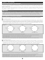
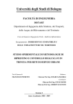
Basics of the Equatorial Mounts
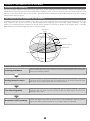
What is an Equatorial Mount?
The SXP Equatorial mount package contains the items listed below.
Check if all the items are included.
Package Consisting of:
In the northern hemisphere, stars appear to turn around the polar
star (the north celestial pole) making approximately one rotation per
SXP Equatorial Mount
1
SX Counterweights 3.7kg and 1.9kg
1
STAR BOOK TEN Hand Controller
1
STAR BOOK Cable
1
Ferrite Core for LAN cable
1
Phillips Head Screwdriver
1
Size M8 Screws
2
Allen Wrenches; one each of 6mm, 5mm, 1.5mm and 0.5 inch
1
Cigarette-lighter Plug Cord
1
Strap for STAR BOOK TEN
1
CR2032 Battery for STAR BOOK TEN's built-in clock
1
day.
This is called diurnal motion and occurs because the earth
turns on its own axis once a day. The equatorial mount is a platform
which is designed to rotate parallel to earth's rotational axis.
Zenith
North Celestial Pole
North Celestial Pole
Polar Axis
Horizon
North Pole
(Checking Purpose Only)
SXP Instruction Manual (This book)
1
Note:
* Your SXP mount package may differ when you purchase it as a
complete telescope package.
South Pole
Equator
* A power supply unit is sold separately.
Earth's Axis
Basic movement of the SXP Mount
Every movement of the electrically driven SXP Mount is fully
controlled by the STAR BOOK TEN hand controller. The mount will
perform smooth and accurate movements when each component on
the mount is balanced correctly. An unbalanced mount may cause
vibrations and can result in tracking errors or failure of rotational
mechanisms. Make sure that the telescope is well balanced.
CAUTION
Do not rotate the mount manually without loosening the
clamp levers.
The SXP mount has clamps which allow you to rotate the Right
Ascension (R.A) and Declination (DEC.) axes freely for quick set up
and compact storage of the mount. Remember to tighten the clamp
levers when you use the mount.
The clamp levers should be
loosened to protect the inner gear train for storage and when you
transport the mount.
Never connect the STAR BOOK cable to other equipment such as a
PC.
This could result in electrical shock, fire, or damage to the
equipment.
(The specifications of the STAR BOOK cable are not
compatible with RS232C connectors.)
Be careful not to bang the mount against other objects. This could
damage the gears and bearings.
4
BEFORE USE
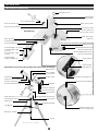
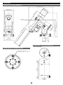
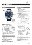
SXP Mount Components
Declination Axis
Mount Head
(Optical Tube Attachment Base)
R.A. Axis(Polar Axis)
Polar Axis Front Cap
DEC. Clamp Lever
Set Position Guidepost
R.A. Clamp Lever
Polar Axis Rear Cap
(Polar Scope Cover)
[SXP Mount]
Polar Axis Scope
(Built-in)
Motor Housing
Counterweight Bar Lock Lever
Counterweight Bar
Altitude Scale
Altitude Adjustment Knob
(For Polar Alignment)
Counterweight Lock Screw
Counterweight 3.7kg
(8.18 lb)
Azimuth Adjustment Knobs
(For Polar Alignment)
Counterweight 1.9kg
(4.2 lb)
Counterweight
Safety Thumbscrew
Power Switch
[ SXP Mount series telescope package with optical tube and tripod ]
DC12V Power
Connecting Port
Safety Screw
Carry Handle
Lock Screw
Dew Shield
Finder Scope
Controller Connecting Port
Objective lens (Inside)
Dovetail Tube Plate
Set Position Guidepost
Eyepiece
Dovetail-plate Mounting Block
Flip Mirror Daigonal
Focuser Draw-tube
Focus Knobs
SXG Half Pillar
Fixing Bolt(Inside)with Grip
Fixing Bolt with Grip
Fixing Knob
SXG Tripod
STAR BOOK TEN
Leg Bracket
Altitude Clamp Lever
(For Polar Alignment)
Extension Clamps
Leg Tip
SXP-AX103S shown as an example
5
BEFORE USE
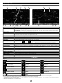
The specifications are subject to change without notice.
SXP Mount Specifications
Mount
SXP Equatorial Mount
DEC. Slow Motion
180-tooth full circle micro-movement gear, 72mm in diameter, Brass wheel
R.A Slow Motion
Worm Gears
R.A. Axis
DEC. Axis
Number of Bearings
Counterweight Bar
Polar Axis Scope
180-tooth full circle micro-movement gear, 72mm in diameter, Brass wheel
9mm in diameter, Brass
40mm in diameter, Carbon steel
40mm in diameter, Carbon steel
15 pieces
20mm in diameter, Retractable
Built-in 6x20mm scope, FoV 8 degrees, Bubble level, Illuminated reticle, Setting accuracy within 3 arc minutes,
Time graduation circle: 10 arc minutes increments between 16h and 8h (the following day)
Date graduation circle: 2-day increments
Meridian offset circle: Adjustable between E20 degrees and W20 degrees in 5-degree increments
Northern hemisphere: Polaris guide scale (Applicable to year 2025)
Azimuth Adjustment
Altitude Adjustment
Drive Motor
Automatic Slewing
Maximum Payload
Controller Cable Connection Port
Powe Connecting Port
Southern hemisphere: Octant 4 stars pattern
Fine adjustments: About ±7 degrees
Twin tangent screws/knobs: About 1.2 degrees per rotation
Latitude between 0 degree ~ 70 degrees, 3-altitude zone setting (high, middle and low latitude, adjustment
rage: ±15 degrees in each zone), Altitude Scale:2-degree increments, Twin T-bar handles: 0.8 degrees per rotation
Stepping (Pulse) motors with 250PPS
High precision “GOTO” slewing with STAR BOOK-TEN, 1000x sidereal rate at maximum
16kg (35.2 lb), (400kg•cm torque load = About 16kg at a point of 25cm from the fulcrum)
D-SUB 9PIN male plug
DC12V EIAJ RC5320A Class4
Electricity Consumption DC12V •0.45~2.2A(at 10kg payload), 0.6A~2.5A (at 16kg payload)
Dimensions
343 x 359 x 128mm
Counterweights
3.7kg (8.15 lb) x 1pc and 1.9kg (4.2 lb) x 1pc
Weight
Optional Accessories
11kg (24.2 lb), excluding counterweights
Dovetail-plate Mounting Block, SXG-HAL130 Tripod, SXG Half Pillar, AXG-P85 Pillar, AC Power Source
STAR BOOK-TEN Specifications
Hand Controller
STAR BOOK TEN
Display
5-inch TFT, WVGA (800 x 480 pixels) 65,536 colors, with backlight
CPU
32bit RISC Processor 324MHz SH7764
Power Connecting Port
DC12V EIAJ RC5320A Class4
Autoguider Port
LAN Port
Controller Cable Connection Port
Expantion Slot
R.A. & DEC. Display Unit
Power Supply
Built-in Clock Batter
Electricity Consumption
Operating Temperature
Dimensions
Weight
Celestial Object
Database
Menus and Major
Functions
6-pole 6-wired modular jack(For external Autoguider)
10BASE-T
D-SUB9PIN male plug
For an optional Advance Unit in future.
R.A.: 1-arc second
, Decl.: 0.1-arc. minute
DC12V(Supplied from the mount side.)
CR2032 x 1
12V•0.5A(Stand alone use)
0~40°C (104F)
169mmL x 154mmW x 30mmH
380g (13.4 oz)(Excluding the built-in battery, cable and optional Advance Unit.)
272,342 (SAO: 258997, NGC objects: 7840, IC objects: 5386, Messier objects: 109*, 7 Planets,
1 quasi-planet, the Moon and the Sun)
*M40 is a missing number. M91 and M102 are listed as NGC4548 and NGC5866 in the database respectively.
Automatic GoTo Slewing, Sidereal tracking and different tracking speeds for the Sun, the Moon, planets,
comets and artificial satellites, Backlash compensation, Permanent PEC, Autoguider, Night vision mode,
Screen brightness control, Hibernate mode, Built-in speaker, LAN connecting update and more. (As of Nov. 2011.)
Applicable OS:
M icr osoft W indow s
M icr osoft W indow s
M icr osoft W indow s
M icr osoft W indow s
M icr osoft W indow s
M icr osoft W indow s
M icr osoft W indow s
M icr osoft W indow s
98Sec ondEdi ti on
M i l l eni um Edi ti on( M e)
XP H om e Edi ti on
XP Pr offes s i onal
Vis ta H om eBas i c
Vi s ta H om ePr em i um
Vi s ta Bus i nes s
Vi s ta U l ti m ate
6
M i c r os oft W i ndow s 7 H om ePr em i um
M i c r os oft W i ndow s 7 Pr off es s i onal
M i c r os oft W i ndow s 7 U l ti m ate
* N ot appl i c abl e to M ac OS, Li nux and U ni x
BEFORE USE
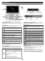
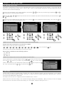
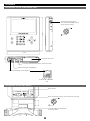
STAR BOOK TEN Components
①
③
②
④
⑤
⑥
⑦
⑧
⑨
STAR BOOK TEN Bottom View
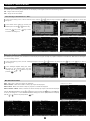
① Color LCD Screen
⑤ Numerical / Command Keys
Displays star charts and information about celestial object and the status
of the mount.
Allows you to enter a number or a command indicated on the keys. The
following commands are allocated.
② Zoom Keys
Commands Functions
*Switches the star chart from Scope Mode to Chart Mode or vice versa.
It will proceed to GoTo slewing if pressed in the Chart Mode.
The zoom keys are used in the following functions.
Enlarge or reduce a displayed star chart on the screen
*Pressing the key will fix your input value and option.
Clears menus and/or dialog boxes displayed on the screen and
returns to the star chart. (If the key is pressed during the initial
settings, the screen will come back to the Initial Configuration menu.)
Enlarge a star chart in both Chart Mode and Scope Mode.
Reduce a star chart in both Chart Mode and Scope Mode.
Calls up the main menu to perform various setups.
Chooses a target from the sun, the moon, or planets slew to.
Scroll the cursor up or down in various menus to change preset
values
Move the cursor step by step or to have the cursor scroll up
every 5 or 6 objects in the Object menu.
(It depends on the size of a dialog box.)
Move the cursor step by step or to have the cursor scroll down
every 5 or 6 objects in the Object menu.
(It depends on the size of a dialog box.)
Chooses a well-known deep sky object like the Andromeda galaxy,
the Pleiades star cluster, and so on from the database to slew to it.
Chooses a mode of the direction keys from AltAzimuth, R.A.Decl.
and X-Y (vertical and horizontal axial movements on the mount).
Chooses a target from the Messier objects database to slew to.
Chooses a target from the NGC or IC objects database to slew to.
Pressing the
key will switch the database alternately
Chooses a bright and conspicuous star such as Sirius, Antares,
and so on from the database to slew to it for star alignment.
Accelerate or decelerate the motor speed between 0.5x and 800x
sidereal rate. (The maximum speed can vary according to a set value.)
Accelerate the motor speed (Linked to zoom in the screen.)
Displays lists of 272,342 celestial objects.
Call up the expansion function menu if an optional Advance
Unit is installed.
Decelerate the motor speed (Linked to zoom out the screen.)
Aligns your telescope.
③ Power Connecting Port for stand alone use
(DC12V EIAJ RC5320A Class4)
⑥ Autoguider Port
④ Direction Keys
Move your telescope manually and scroll the star chart on the screen or move
the cursor. (Also the key is referred to as ENTER in some dialog boxes.)
⑦ LAN Connecting Port
S c r o l l i ng s t a r c h a r t s
(10BASE-T)
⑧ Mount Connecting Port
The displayed star chart on the screen can be scrolled up
and down or back and forth with the
• •
•
keys if
the setting is in AltAz mode. If the direction key setting is
in R.A/DEC or X-Y mode, the • keys allow scrolling in
the direction of DEC. and the
•
keys allow scrolling
sin the direction of R.A..
⑨ Expansion Slot for Advance Unit sold separately
Move the cursor up and down or back and forth with the
• •
•
keys.
Also,
: Advance a cursor such as the enter key.
(It does not fix the entered value.)
: Back to a previous dialog box or screen.
7
BEFORE USE
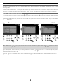
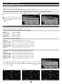
Screen Menus and Instructions
①
⑧ ⑨
②
⑩
⑪
Item
① Display Mode
⑫ ⑬
③
④
⑭
⑮
⑤
⑥
⑯
⑦
⑰
⑱
⑲
Description
SCOPE MODE : The telescope is linked with the star chart. The telescope follows in the same direction as the star
chart is scrolled.
C H A R T M O D E : The telescope is independent of the star chart. The star chart is scrolled to select a target object.
② Zenith Mark
③ Target Object
④ Date
⑤ Battery Level
⑥ R.A. Grid
⑦ DEC Grid
⑧ Telescope Icon
Indicates the zenith and north-south-east-west directions.
Indicates the direction where the telescope is pointing or the section of the area where a target is centered. The
two concentric circles show areas in an angular field of view.
Local time of your observing site.
Indicates the level of battery discharge if the AC Adapter is not used.
Parallel of longitude. 0h to 23h at one-hour intervals.
Parallel of latitude. Between -90deg. and +90 deg. at 10°intervals.
Tracking ON / OFF
:ON
:OFF
*The counter is displayed while the PEC is in operation.
⑨ Telescope Coordinates Displays the direction of your telescope in Right Ascension and Declination.
⑩ Azimuth / Altitude
⑪ Target Circles
⑫ Target Name
⑬ Target
⑭ Target Coordinates
⑮ Zoom Level Indicator
⑯ Motor Speed
⑰ Horizon
⑱ Number of Alignment
⑲ Direction Key Mode
Displays the direction of your telescope in azimuth (left and right) and altitude (up and down) .
Indicates the direction where the telescope is pointing or the section of the area where a target is
centered.The two concentric circles show areas in an angular field of view.
Indicates a target by number or its common name(within 10 characters).
The heading of your target information.
Displays coordinates of the selected target in R.A. and DEC.
Levels of zooming up or down the star chart by graph.
Displays a maximum motor speed at a given zooming rate.
The line corresponds to the horizon.
Number of aligned objects.
Indicates the orientation of the direction keys
•
•
•
by AltAz, RA DEC or X-Y mode.
Legend *1
Icon
Object
Icon
Object
Icon
Object
Galaxy
Moon *3
Uranus
Deffuse nebula
Mercury
Neptune
Globular clusters
Venus
Pluto
Star clusters
Mars
Comet *4
Planetary nubula
Jupiter
Satellite *5
Sun
Saturn
*1: These icons are different from actual viewing images of the celestial objects. Except the Sun and the Moon, the size of the icons is unchangeable.)
*2: It is not designed to simulate a transit of a planet on the surface of the Sun and a solar eclipse.
*3: The appearance of the waxing and waning of the moon displayed on the screen is for illustrative purpose. It is not suitable for accurately simulating an
occultation of the moon or a lunar eclipse.
*4: Register orbital elements of a comet to display.
8
BEFORE USE
Flow of Operation
Take the following steps to set up and use the SXP equatorial mount series correctly.
P10~19
① Preparation
● Set up the tripod on a level ground.
● Balancing the mount.
② Initial Setting
● Set the Language (The first time only)
Turn on power to the STAR BOOK TEN and set your language.
P20~23
● Set date, time and time zone (The first time only)
Enter date, time of your observing site and time zone into your
STAR BOOK TEN.
● Set longitude and latitude. Enter longitude and latitude of your
observing site into your STAR BOOK TEN.
P24
③ Basic Operation
● Learn and understand the basic operations of the SXP mount.
P25~52
④ Go-To Slewing to Celestial Objects
● Begin with the Home Position
Run the motors of the SXP mount by the STAR BOOK TEN to
position the mount toward the home position.
● Align the telescope
Choose two (or more) reference stars from the database to align
the telescope.
● Automatic Go-To Slewing
Once the alignment is completed, enjoy your observing as the
STAR BOOK TEN will point you to your target object.
P53~98
⑤ Application
● Use various functions and applications.
9
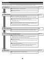
Chapter 1 PREPARATION
About the Internal Battery of STAR BOOK TEN
The STAR BOOK TEN controller has a built-in clock, which runs on a CR2032 battery. As the battery is not inserted in the STAR
BOOK TEN at Vixen's factory before shipment insert it when you use the STAR BOOK TEN for the first time. The provided battery
is for factory inspection and not designed for long term use. (The STAR BOOK TEN is usable even if its internal battery is
exhausted, but you will need to set up your local time every time you power on the STAR BOOK TEN.)
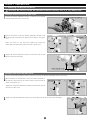
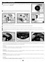
Inserting the Battery
1
Remove the cover of the battery container on the back of the STAR
BOOK TEN by removing the screws with the provided Phillips
screwdriver as shown in the figure.
Phillips screwdriver
cover
2
Insert a fresh battery into the inside of the container so that its
positive polarity faces upward. Placing the battery in the wrong
direction could result in damage or malfunction.
3
Screw the cover back in place.
Replacing the Battery
4
5
Remove the cover of the battery container on the back of the STAR
6
Push out the battery from the inner side as shown in the figure.
7
Insert a fresh battery so that its positive polarity faces upward.
BOOK TEN.
Press the edge of the battery with your fingertip and pull up the
battery.
Screw the cover back in place.
CAUTION
Use a wooden stick or an object with non electric conductivity to avoid malfunction or damage to the STAR BOOK TEN when you remove the
battery. Do not allow liquids or foreign objects or a finger to enter the battery container. This could result in damage or electrical shock.
10
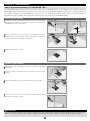
Chapter 1 PREPARATION
Assembling the Mount
Refer to each instruction manual of your telescope and accessory together with this manual when you attach them to the mount.
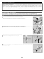
Ⅰ. Setting up the Tripod
1
2
3
Place the tripod on a level ground to make the telescope stable during
4
Attach the metal post on the tripod head. Thread the metal post into
Extension clamp
observation. Pull the tripod legs apart until each leg is fully extended.
2
3
Loosen the extension clamp on the tripod leg so that the tripod leg
can be adjusted.
Tighten the extension clamp to hold the tripod leg securely in place.
Tighten the metal post until the end of the thread securely; otherwise
4-2
4-1
the hole marked as SXP and tighten it with a screwdriver.
Screwdriver
SXP
it could cause a bending a break.
SXG-HAL130三脚
North
Position the tripod so that the metal post comes to north.
Post
Attaching the SXG Half Pillar
Proceed to the step II if this accessory is not provided for your telescope.
1
Put the vanity ring on the thread of the metal post and attch the metal
1-1
post on the head of the half pillar. (1-1)
1-2
Allen wrench
There are two threaded holes on the head of the half pillar. Thread
Post
Vanity Ring
the metal post into the outer hole and tighten it with the supplied Allen
wrench.
Post
Vanity Ring
Outer Hole
SXG Half Pillar
2
SXG Half Pillar
Loosen the fixing knob on the lower part of the half pillar in advance
2-1
and put the half pillar on the tripod head. (2-1)
2-2
Attach the half pillar on the tripod head so that the center projection
on the bottom of the half pillar fits the center hollow on the tripod
head. (2-2)
Tighten the lock knob beneath the tripod head to secure the half
Fixing Knob
Hole
Hole
Post
pillar. (2-3)
Tripod
ハーフピラー
North
Post
2-3
Lock Knob
Lock Knob
Place the tripod so that the metal post on the SXG Half Pillar faces north.
11
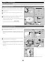
Chapter 1 PREPARATION
Ⅱ. Attaching the Equatorial Mount
CAUTION: Be sure to handle the equatorial mount carefully as it is a very heavy item.
Package without the SXG Half Pillar
1
Loosen the azimuth adjustment screws in advance by turning the
Azimuth Adjustment Knob
azimuth adjustment knobs on the mount.
Azimuth Adjustment Knob
2
Position the mount so that the azimuth adjustment screws of the
2-1
mounting base come above the metal post as shown in the figure.
2-2
(2-1)
Place the mount on the tripod and tighten the fixing bolt
underneath the tripod head to hold the mount in place. (2-2)
Post
Lock Knob
3
Tighten the azimuth adjustment screws on the mount base so that
3
the two knobs are set equally.
Azimuth Adjustment Knobs
Package with the SXG Half Pillar
1
2
Loosen the azimuth adjustment screws in advance by turning the azimuth adjustment knobs on the mount.
Attach the mount on the half pillar so that the center projection on
the bottom of the mount fits the center hollow on the half pillar as
Azimuth Adjustment Knob
2-1
2-2
shown in the figure. (2-1)
Tighten the fixing bolt underneath the head of the half pillar to hold
the mount in place. (2-2)
3
Lock Knob
Post
Tighten the azimuth adjustment screws on the mount base so that the two knobs are set equally.
2-3
Azimuth Adjustment Knob
12
Chapter 1 PREPARATION
Tips on Assembling the Mount
Generally equatorial mounts are heavier on the declination axis side. Because of this feature, placing the equatorial mount so that its
declination axis comes directly over one of the tripod legs can make the equatorial mount most stable when you use the equatorial
mount for a north (or south) latitude of 50 degrees and lower. However, the balance of the equatorial mount may vary if the equatorial
mount is used in latitude higher than 50 degrees.
This may result in shifting the center of balance to the opposite side of the
declination axis depending on the location of the loading equipment.
mount becomes more stable in such a case.
Change the position of the tripod legs so that the equatorial
Ⅲ .Attaching the Counterweight
The counterweight bar is in the declination body. You may balance the SXP mount with only the counterweight bar to start.
CAUTION: Be sure to handle the counterweight carefully as it is a very heavy item.
1
Loosen the counterweight bar lock lever to draw out the counterweight bar.
Lock Lever
Tighten the counterweight bar lock lever with the counterweight bar extended fully.
Counterweight
Bar
2
Remove the safety screw on the end of the counterweight bar. Loosen the lock screw on the side of a
counterweight and install the counterweight by sliding it onto the counterweight bar.
Safety Screw
3
Attach the counterweight so that the lock screw on the counterweight
is on the far side of the safety screw as shown in the figure.
Counterweight
↑
Far Side
Lock Screw
Lock Screw
4
Tighten the counterweight lock screw and replace the safety screw to screw it down on the end of the
counterweight bar tightly.
Safety Screw
13
Chapter 1 PREPARATION
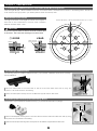
Ⅳ .Attaching a Saddle Plate or a Dovetail-plate Mounting Block
There are eight M8 pich 1.25mm threaded screw holes on the mount head of the SXP mount as shown in the drawing below. Choose the
screw holes that are appropriate to your saddle plate that holds the telescope tube.
M8 thread screw holes
The eight screw holes are arranged at intervals of 45 degrees to
Thread: M8 (Pitch 1.25mm) Allowable Depth: Up to 11mm
each other on the circumference of a 35-mm circle in diameter.
Maximum allowable depth: 11mm
CAUTION
Do not use long bolts which exceed the maximum allowable depth
A1
of the thread. This could result in damage to the mount head.
○ GOOD
A2
× BAD
Collide against the
inside components
M8 Bolt→
Maximum
Allowable
Depth
Inside Components
A4
A3
×
A3
A4
A2
Inside Components
A1
Attaching a Saddle Plate
This mounting platform is included as standard accessory if you purchase a VMC260L optical tube as a package
with the SXP Mount.
1
2
Allen wrench
M8 Bolt
Place the saddle plate on the mount head so that the screw holes match each other by using the
position of B1 or B2 marked on the drawing.
M8 Bolt
Attach the saddle plate securely with the two M8 bolts supplied with the SXP mount.
Saddle Plate for VMC260
Attaching the Dovetail-plate Mounting Block
This accessory may be included as standard accessory if you purchase the telescope as a package.
M8 Bolt
1
2
Place the dovetail-plate mounting block on the mount head so that the screw holes match each other by using
Allen wrench
M8 Bolt
the position A1 or A2 marked on the drawing.
Attach the dovetail-plate mounting block securely with the two M8 bolts supplied with the SXP mount.
14
Dovetail-plate Mounting Block
Chapter 1 PREPARATION
V . Attaching the Optical Tube
Make sure that the slide bar or dovetail tube plate is flat against the saddle plate. Tightening the lock screws with a gap between these
parts cause the telescope to fall.
Attaching to the Saddle Plate
1
Loosen the two lock knobs on the saddle plate before you attach the optical tube.
2
Slide the dovetail bar on the bottom of the optical tube onto the sunken platform of the saddle plate.
3
Tighten the two lock knobs on the saddle plate securely.
1
Attaching to the Dovetail-plate Mounting Block
Loosen the lock knob and the safety screw before you attach the optical tube.
Safety Screw
Lock Knob
2
Slide the dovetail tube-plate mounted optical tube onto the sunken platform of the dovetail-plate
mounting block.
Optical Tube
Dovetail-plate Tube Plate
3
Tighten the lock knob onto the dovetail tube-plate centering notch until snug.
screw securely.
Tighten the safety
Safety Screw
Lock Knob
15
Chapter 1 PREPARATION
Ⅵ . Balancing the Equatorial Mount
Why Balance the Mount?
The Vixen SXP mount is a German equatorial mount, in which the rotating RA axis and rotating DEC axis cross each other at right angle.
The axes are rotated by using movements of gears on the each axis to get maximum stability and limit the stress on the gears.
equatorial mount is in an unbalanced state, it will increase stress to the gears and this could result in damage or erratic operation.
If the
Precise slewing requires a high level of accuracy in rotation of both axes and is important in eliminating stress to the gears. Make sure to
balance the equatorial mount properly in RA and DEC accordingly.
An optical tube weighing 1.3kg (2.8 lb.) or less is not balanced with the SXP mount.
CAUTION
Take care not to drop the optical tube assembly as it could seriously damage the equipment or lead to injury. Pay close attention to
the security of the telescope tube and do not excessively loosen the lock knobs on the equipment.
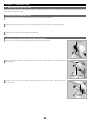
Balancing the Mount in Declination
TelescopeTube with Dovetail Slide Bar
1
Loosen the R.A. clamp while holding the counterweight bar (1-1)
1-1
and turn the telescope tube until the
DEC. axis comes to horizontal (1-2).
loosen the DEC. clamp.
1-2 2-1
Decl. Axis
Tighten the R.A. clamp and
Be sure to hold the optical tube or
counterweight in hand while loosing the clamps.
Counterweight
Bar
2
R.A. Clamp
Release the telescope gradually to see which way the telescope rotates around the declination axis.
If the telescope tube starts rotating as you release, it shows there is an imbalance in DEC.
DEC. Clamp
Lock Knob
2-2
To determine the balance point, loosen the lock knob that hold the telescope tube to the dovetail-plate
mounting block and slide the telescope tube either forward or backward until it remains stationary.
CAUTION
Do not loosen the lock knob too much in balancing. This could drop off the telescope tube or lead to
Dovetail Slide Plate
injury.
3
Tighten the lock knob (and the safety screw) securely to hold the telescope tube in place.
4
Tighten the DEC clamp to finish this adjustment.
Lock Knob
Standstill
16
3
Chapter 1 PREPARATION
Telescope Tube with Tube Rings
1
Loosen the R.A. clamp while holding the counterweight bar (1-1) and turn the telescope tube until the
DEC. axis comes to horizontal (1-2). Tighten the R.A. clamp and loosen the DEC. clamp. Be sure to
hold the optical tube or counterweight in hand while loosening the clamps.
Lock Knob
AX103S shown
Release the telescope gradually to see which way the telescope rotates around the declination axis.
2
If the telescope tube starts rotating as you release, it shows there is an imbalance in DEC.
To determine the balance point, loosen the tube ring lock knobs that hold the telescope tube and slide
the telescope tube either forward or backward until it remains stationary.
CAUTION
Lock Knob
Do not loosen the lock knobs too much in balancing. This could drop off the telescope tube or lead
to injury.
3
4
R200SS shown
Tighten the tube ring lock knobs (and the safety screw if any) securely to hold the telescope tube in place.
Tighten the DEC clamp to finish this adjustment.
Balancing the Mount in R.A (Right Ascension)
1
Loosen the R.A. clamp while holding the counterweight bar and turn the telescope tube until the DEC axis comes to horizontal as shown
2
Release the telescope tube gradually to see which way the telescope rotates around the R.A. axis. If the telescope tube starts moving by
in the figure.
its own weight as you release, it shows there is an imbalance in the R.A.
While holding the counterweight bar, loosen the lock knob on the counterweight so that it can be
moved to a point where it balances the telescope tube.
This is the point at which the telescope
Lock Screw
remains stationary when the R.A. clamp is loose.
If your telescope is light in weight, the mount may balance without the supplied counterweight. (The
extended counterweight bar itself can act as a counterweight.)
Retract the counterweight bar for
further balance adjustment.
Decl. Axis
Counterweight
3
4
Tighten the lock knob on the counterweight to hold in place.
Standstill
Tighten the R.A. clamp on the mount securely.
CAUTION
Do not move the counterweight too much in balancing. This could damage the telescope tube or lead
to injury.
17
Chapter 1 PREPARATION
Tips on Proper Balancing
The balance arrangements below illustrate various possible settings, depending on the length and weight of your optical tube. The center
of gravity of the telescope is given as 25cm from the intersection of the R.A. and DEC axes.
No counterweight:
A 3.7 kg (8.1 lb) counterweight:
from 1.3kg (2.8 lbs.) up to 2.0kg (4.4 lbs.)
from 5.7kg (12.5 lbs.) up to 9.2kg (8.6 lbs.)
25cm
48.4cm
25cm
24.7cm
3.7kg
1.3〜2. 0k g
5 .7 〜 9 .2 k g
( 32.5〜5 1 . 4 k g・m )
(142.8〜230.5kg・m)
3 . 7 kg
A 1.0kg (2.2 lb) counterweight:
A 3.7kg (8.1 lb) & a 1.9kg (4.1 lb) counterweights:
from 2.9kg (6.3 lbs.) up to 3.9kg (8.5 lbs.)
from 8.0kg (17.6 lbs.) up to 12.4kg (27.3 lbs.)
25cm
25cm
4 7 .1 c m
48.4cm
42.2cm
28.9cm
22.7cm
2 3 .1 c m
1 .0 k g
1.0kg
1.9kg + 3.7kg
2.9〜3. 9k g
8 .0 〜 1 2 .4 k g
( 7 4 .5 〜 9 8 . 5 k g・m )
(201.4〜310.6kg・m)
1 . 9 kg + 3 . 7 kg
A 1.9kg (4.1 lb) counterweight:
A 3.7kg (8.1 lb) & a 2.8kg (6.1 lb) counterweights:
from 3.7kg (8.1 lbs.) up to 5.5kg (12.1 lbs.)
from 9.2kg (20.2 lbs.) up to 13.8kg (30.3 lbs.)
25cm
25cm
4 6 .4 c m
48.4cm
41.2cm
30.9cm
23.7cm
2 2 .7 cm
1 .9 k g
1.9kg
2.8kg + 3.7kg
3.7〜5. 5k g
9 .2 〜 1 3 .8 k g
( 9 4 .5 〜 1 3 9 . 5 k g・m )
(232.1〜345.8kg・m)
A 2.8kg (6.1 lb) counterweight:
Two 3.7kg (8.1 lb) counterweights:
from 4.7kg (10.3 lbs.) up to 7.3kg (16.0 lbs.)
from 4.7kg (10.3 lbs.) up to 7.3kg (16.0 lbs.)
25cm
25cm
4 7 .4 c m
2 . 8 kg + 3 . 7 kg
48.4cm
40.2cm
32.9cm
24.7cm
2 3 .7 c m
2 .8 k g
2.8kg
3.7kg + 3.7kg
4.7〜7. 3k g
1 0 .5 〜 1 5 .1 k g
( 1 1 7 .7 〜 1 8 4 . 1 k g・m )
(264.5〜379.2kg・m)
18
3 . 7 kg + 3 . 7 kg
Chapter 1 PREPARATION
Ⅶ . Connecting the STAR BOOK Cable
Connecting to the Mount
1
Plug one end of the STAR BOOK cable, where no ferrite core is
2
Secure the connector with the setscrews.
attached, into the connecting port on the mount for the controller
Controller Connecting Port
1
2
cable.
Setscrews
Connecting to the STAR BOOK TEN
1
Plug the other end of the STAR BOOK cable, where the ferrite core is attached, into the connecting
2
Secure the connector with the setscrews.
port on the STAR BOOK TEN for the controller cable.
CAUTION
* Hold the connector part of the STAR BOOK cable securely and pull it straight when you unplug the cable. Unplugging by grabbing the cable
part may cause a wire to break.
* Avoid pulling or bending a part of the cable adjacent to the connectors. It may cause a wire to snap.
* Never connect the STAR BOOK cable to other equipment such as a PC. It may cause failure, fire or electrical shock. (The STAR BOOK cable
does not meet the RS232C specifications.)
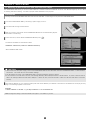
Ⅷ . Connecting the Power Cable
Use an optional AC Adapter 12V-3A or portable power supply with
the supplied cigarette-lighter plug cord.
Specifications:
The portable power supply is sold separately.
Confirm that the power switch is turned OFF (i.e. the O mark on the
switch is depressed) before you plug the power cable to the DC12V
input of the mount.
DC12V EIAJ RC5320A
Class4 center positive (+)
CAUTION
* When you unplug the power cable, be sure to hold the connector part and pull it straight. Unplugging by grabbing the cable part may cause a
wire to snap.
* Avoid pulling or bending a part of the cable adjacent to the connectors. It may cause a wire to snap.
* Do not use the power cable in a folded and tied condition. It may cause electrical shock or fire.
19
Chapter 2 INITIAL SETTING
Basic functions of the mount are described in this chapter. For advanced functions refer to Chapter 5 “Application”.
Ⅰ . Turning ON the Power
1
2
3
The power switch is located on the bottom of the declination body of the mount. To turn on the power press the side marked I on the
switch and to turn off the power, press the O marked side on the switch.
Turning on the power switch displays the Vixen logo on the screen of the STAR BOOK TEN.
The "Initial Configuration" menu is displayed.
1
2
3
Power Switch
Note: Your stored data in the memory may be initialized due to replacement of the built-in battery, firmware version update, or if the
built-in battery is exhausted. If this happens: “Memory Error!! Initialized Memory Data” is indicated on the screen and all memory is
erased and the STAR BOOK TEN reverts back to default settings.
Ⅱ . Setting 言語/Language
Language is available in Japanese, English, German, Italian and Spanish on the STAR BOOK TEN as of December 2011. The setting is defaulted to "Japanese".
1
2
3
In the “Initial Configuration” menu, choose “言語/Language” with the
_ or
direction key and press the
key (or the
key) to
call up the dialog box.
In the “Language” dialog box, choose “English” with the
or
direction key and press the
key.
Now it is available in English language.
1
2
Note: You can also access the “Language” dialog box from “System Menu”.
20
3
Chapter 2 INITIAL SETTING
Ⅲ . Setting Local Time
This setting is required the first time you use the STAR BOOK TEN or when the internal battery has been changed. You can enter date and
local time of your area using 24 hours clock, i.e. 3pm is 1500.
It does not offset daylight saving time. (The last entered date and time
information will be stored and displayed.)
1
2
3
Choose "Local Time Setting" in the "Initial Configuration" menu with the
or
key to access the "Local Time Setting" dialog box.
With the
or
•
•
direction key.
•
key (zoom key or direction key) and press the
(or
)
direction keys move the cursor to an available entry space and enter the date and your local time with the
Once you fill in the complete time, the cursor shifts to OK. Press the key to complete the local time setting. Then, press the key
again to come back to the “Initial Configuration” menu.
1
2
3
Note: You can also set date and your local time by number with the command keys.
Example: Enter date of December 21, 2012 and time of 18h05m:
Move the cursor to the entry space for date and time.
→ →/ →
→/
→
→
→
→/
→
→:
→
in turn and press the key.
The cursor will move forward automatically as you enter the numbers.
Date formats are available from the following 3 patterns:
YY/MM/DD
MM/DD/YY
DD/MM/YY
Note: You can always access the Local Time Setting from "System Menu".
Choose “Date Format” in the entry dialog box with the
press the
or
or
zoom key (or direction key) and
zoom key (or direction key) and press the
Format. Move the cursor to your desired date format with the
key. Then, choose OK with the
or
key and press the
key to access the Date
or
key and press the
key.
Time Zone
The time zones are based on longitude bands 15 degrees wide, starting at Greenwich, England. Set the time difference in hours between
your local time and Greenwich Mean Time (GMT). The sign is “+” (plus) if local time is ahead of GMT (east of Greenwich) and “-“ (minus) if
local time is behind GMT (west of Greenwich).
For example, the time zone for Los Angeles (on Pacific Standard Time) is -8 hours.
Please note that the time zone setting is not converted to Daylight Saving time automatically.
When you reset your clocks for Daylight
time, add one hour to the value in the Time Zone setting, as in Los Angeles, change the setting from -8 to -7.
21
Chapter 2 INITIAL SETTING
Ⅳ . Setting Location
This setting is required the first time you use the STAR BOOK TEN or when you change the internal battery or when you travel to a distant
observing location.
Enter the name, longitude (east or west), latitude (north or south) and time zone (plus or minus) of your main observing location. Up to 10
different locations can be entered. The longitude and latitude of your observing location can be checked on a map or with a GPS device.
The location is defaulted to Tokyo (E139.42, N35.42, TZ+9), Japan. (The last entered location information will be stored and displayed.)
Enter a New Observing Location
1
2
3
In the initial setting menu choose ”Location” with the
box.
With the
Press the
key.
or
or
direction key and press the
(or
key to access the location entry dialog
direction key, move the cursor to an available entry space where no location information is shown. (Tokyo is set as default.)
key to display the “New Object” dialog box. Enter the name of your observing location by alphabet with the
1
•
direction
2
3
A line of entry spaces accepts a maximum of twenty words
Note: Pressing the
or
zoom key will move the cursor to the next available entry space. (Here, the
•
direction keys are not
allocated for moving the cursor in vertical directions.)
4
5
Enter the longitude, latitude and zone of your observing location in turn with the
the time zone, the cursor shifts to OK.
Press the
key to complete the location setting. Then, press the
or
direction key or by number directly. Once you fill in
key twice to come back to the “Initial Configuration” menu to OK.
22
Chapter 2 INITIAL SETTING
Setting, Changing or Deleting the Location Information
1
2
To use your observing location, move the cursor to "Location" in the "Initial Configuration" menu with the
(or
) key to access the location entry dialog box.
Choose the observing location you want to use from the location information with the
box appears to confirm your option. Press the
key again to set the chosen location.
1
or
or
key and press the
key and press the
key. The dialog
2
OK: Choose OK to set a new observing location you chose.
Change Data: Choose “Change Data” to rewrite the observing location.
When you change an observing location in the location information, call up the observing location you want to rewrite in the dialog box
and choose “Change Data” with the
or
direction key. Then, follow instructions for entering a new location as stated above
Delete: Choose “Delete” to clear the observing location.
Available letters and characters for the names are as follows:
!"#$%&'()*+,-./0123456789:;<=>?@ABCDEFGHIJKLMNOPQRSTUVWXYZ[\]^_`abcdefghijklmnopqrstuvwxyz{|}~
23
Chapter 3 BASIC OPERATION
Moving the Telescope
1
Make sure that the R.A and DEC clamps on the SXP mount are locked tightly. Advance
2
3
Choose OK with the
4
Your telescope is ready to slew to all directions as soon as the telescope's home
1
the “Initial Configuration” screen in the following procedure to display the telescope's
home position setting screen
or
key in “Initial Configuration” and press the
display the “Warning” screen for solar observation.
Then, choose “Confirm” with the
or
key and press the
telescope home position setting screen. Pressing the
key to
R.A clamp
key to display the
key will return the screen to
the initial setting menu at this stage.
DEC clamp
position setting screen is displayed on the screen.
2
The
and
and
3
direction keys move your telescope in the direction of the R.A. The
direction keys
Mo v
es i n t h e R
.A.
d
DEC Axis
ire
ct
io
on the right side of the STAR BOOK TEN move the telescope in the direction of the
4
n
DEC.
Polar Axis
M o v es in the
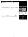
Changing the Go-To Slewing Speed
You can slew the telescope at different speeds through use of the direction keys.
Default slewing speed: 500x of the sidereal rate at a maximum
Note: If the slewing speed is set at level 3 or below in “System Menu”, the maximum
available slewing speed is restricted within 400x of the sidereal rate.
speed levels, refer to “Mount Setting” section in Chapter 5.
For using other
In the telescope's home position setting screen, pressing either of the zoom keys on the
left side of the STAR BOOK TEN will quickly vary the maximum slewing speed. The upper
key
will decrease the motor speed and the lower key
These keys are useful in
SCOPE MODE
will increase the motor speed.
when you need a slow motion at high
magnification or a quick motion at low magnification.
24
dire
DEC
cti
on
Chapter 4 AUTOMATIC GOTO SLEWING
Automatic Go-To Slewing
The moon and bright planets are found readily in the night sky as you can locate their positions with ease.
However, less bright planets,
nebulae and star clusters are dim and mostly invisible with the unaided eye. Even if you know where these dim and blurred objects are in the
night sky, it often takes time and effort to look for them. The automatic Go-To slewing with the STAR BOOK TEN will assist you in locating
celestial objects easily and quickly.
The principle of the automatic Go-To Slewing
It appears that the positions of stars relative to each other in the sky are all but fixed due to their extrmemly long distances from us on the
earth.
Because of this, the star's positions on celestial spheres can be measured on star maps using celestial coordinates.
ascention of the celestial spheres corresponds to latitude and the declination corresponds to altitude on the geograhic maps.
BOOK TEN acts as a celestial navigator like your car navigation system.
The right
The STAR
Celestial Pole
Polaris
天体 ★
Celestial Object
Declination (Degree)
Celestial Equator
Ecliptic
Equinox
Right Ascension (Hour Angle)
Startup Procedure
Locating the Mount
Setting Home Position
Two Star Alignment
Automatic GOTO slewing
Point the mount toward the north celestial pole in the northern hemisphere (the south in the
southern hemisphere) so that the R.A. axis on the mount is parallel with the axis of the celestial
sphere in your observing location.
Loosen the clamps on the R.A and declination axes and move the telescope to the home
position by hand. Point the optical tube to due west horizon in the northern hemisphere (due
east horizon in the southern hemisphere) to fix the home position.
Select two stars from the list in the STAR BOOK TEN to align the telescope.
The more
alignment stars you select, the more centrally located the target objects will be in your
telescope's field of view.
Choose your target on the screen of the star chart or from the database of extensive celestial
objects in the menu and slew the telescope to your target. Enjoy your observing!
25
Chapter 4 AUTOMATIC GOTO SLEWING
Ⅰ . Locating the SXP Mount
After setting up the telescope, locate the SXP mount so that its R.A. axis points toward the north celestial pole if you use the telescope in the
Northern hemisphere. If your intention is not to take lengthy astrophotography, you don't need to align the R.A. axis to the celestial pole
precisely. A rough setting will work well for visual observation. While looking for the polar star, locate the mount so that it faces toward the
north and the elevation of the R.A. axis matches the latitude of your observing site.
Reading Guide
Azimuth Adjustment Knobs
Altitude Scale
Altitude Adjustment Knobs
• Loosening the adjustment screw on one side will allow you to tighten the screw on the other side to change the altitude and azimuth directions.
• If you use the telescope in the Southern hemisphere, locate the SXP mount so that the RA axis points toward the south celestial pole and set
the elevation of the mount to be equal to the latitude of your observing site.
Ⅱ . Home Position
1
Flipping on the power switch on the bottom of the declination body of the SXP mount will
turn on the STAR BOOK TEN. Complete all the initial settings such as time and location.
Advance the screen on the STAR BOOK TEN until the image shown on the right appears
on it. Use an eyepiece with magnification as low as possible.
Note: If the star chart is already displayed on the screen, turn off the power switch and
reboot the STAR BOOK TEN to start from the initial setup screen
2
In the “Initial Configuration” menu, choose OK with the
3
Loosen the R.A. and Declination lock clamps on the mount and position the telescope's
or
key and press the
The “Solar Warning” notice appears on the screen. Choose “Confirm" with the
and press the
key to advance.
optical tube so that it points toward the west and is level.
or
key.
key
Refer to the image of the
telescope displayed on the screen to understand it correctly. When you fix the position of
the optical tube, tighten the R.A. and declination lock clamps on the
mount. After this, do not touch the lock clamps until you finish your
North
observing. The home position is the first positioning of your telescope
to determine. Set the home position by measuring with your eye as
close as possible.
Polar Axis
About home position guideposts
The SXP mount has guideposts on the R.A. and Declination individually.
The guideposts are useful when you position the telescope tube to be
Bad
level toward west in the northern hemisphere (toward east in the
North
Guidepost
southern hemisphere).
Guidepost
Polar Axis
The position of the guidepost on the Declination can be shifted back and
forth for readjustment depending on a telescope tube mounted
Grubscrew
The Declination guidepost can be loosened by the suppied Allen wrench
as shown in the figure so that you can shift it to a desired position.
1.5mm Allen Wrench
Guidepost
26
Chapter 4 AUTOMATIC GOTO SLEWING
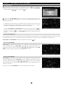
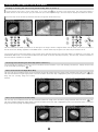
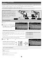
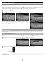
Ⅲ . Alignment
1
2
After determining the home position of your telescope, press the
key to display the
interactive dialog box on the screen. The dialog box asks you if you enter SCOPE MODE .
Choose OK with the
or
key and press the
key.
The star chart in SCOPE MODE appears on the screen. The concentric target circles in the
center of the star chart indicate due west.
(The target circles indicate due east in the
southern hemisphere.)
The SXP mount starts tracking at the celestial rate from that point and now the Go-To
slewing will accurately bring a target object in the finder scope's field of view. You need to
proceed to star alignment to set the pointing accuracy of your telescope.
After this, CHART MODE and SCOPE MODE will switch over each time you press the
key
while the star chart is displayed on the screen. Its status is displayed at the upper left on
the screen.
Pressing the
key in CHART MODE will ask you to proceed to the Go-To
slewing.
What is Star Alignment?
The star alignment matches celestial coordinates of stars memorized as location information in the STAR BOOK TEN with positions of stars that
can actually be seen in the sky. The location information is identified with a star and this paring is called “getting an alignment point”.
CHART MODE and SCOPE MODE can switch over each time you press the
key.
What is SCOPE MODE?
SCOPE MODE is linked with the movements of your telescope. The top and bottom of the
screen are highlighted in red in SCOPE MODE . The telescope follows the target circles on the
starscreen as you scroll the star chart with the
•
•
•
direction keys in SCOPE
MODE . The Go-To slewing is simple with the command keys.
What is CHART MODE?
CHART MODE is independent from the movements of your telescope. The top and bottom of the
screen are highlighted in blue in CHART MODE .
the chart is quick and easy with the
•
With no linkage to the telescope, scrolling of
•
•
direction keys. Go-To slewing is
readily available with the command keys. Additionally, you can look for a target directly on the
star chart in this mode.
The screen will turn to SCOPE MODE as soon as the telescope gets to the target.
27
Chapter 4 AUTOMATIC GOTO SLEWING
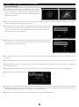
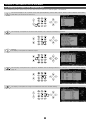
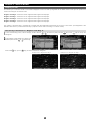
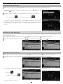
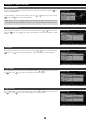
3
Select a star from an alignment stars list in the object database. Be sure to select alignment
stars for which you recognize locations in the night sky. Aldebaran in Taurus, the Bull is
shown here as an example of the first alignment star.
In SCOPE MODE , press the
“Object Menu” with the
or
command key (or the
key, and press the
command key to access “Star” in
key).
Select stars that are available for alignment (stars marked with ◎ are seen above the
horizon.) with the
or
direction key and press the
key.
The dialog box appears to confirm if you are ready to slew the telescope to the target you
selected. Choose OK and press the
key to start the Go-To slewing. At the same time,
the target is marked and a position of the first alignment star is indicated on the bottom of
the screen by its coordinate
Note: If the “Go-To message” is set to off, the Go-To slewing will start at once without
confirmation. This chapter assumes that the “Go-To message” is set to on.
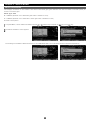
The telescope starts moving toward the
target. (Go-To is indicated on the lower right
of the screen.)
Go-To slewing is completed.
As soon as the Go-To slewing finishes, the
STAR BOOK TEN rings the chimes and the
slewing speed is changed to the sidereal
rate.
28
Chapter 4 AUTOMATIC GOTO SLEWING
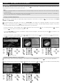
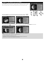
4
Your first Go-To slewing may not bring the alignment star in the main telescope's field of
view but should appear in the finder scope.
Here, center Aldebaran in the telescope's field of view as an example with the following
procedure.
Move the telescope with the
•
•
•
direction keys so that you bring Aldebaran to
the center of the finder scope's field of view. Magnifying the star chart with the zoom key
will slow the motion of the telescope and thus allow you to make finer adjustments of the
position.
Bring Aldebaran in the center of the finder scope's field of view and look for it in the
Finder scope's field of view
telescope's field of view.
Note: Aldebaran will be away from the center of the target circles on the screen as you move
the telescope to look for Aldebaran in the field of view of the telescope. This is caused by a
difference between the actual position of Aldebaran viewed and the location of the same star
in the database of the STAR BOOK TEN. It is a normal behavior. In this stage of the star
alignment, the telescope's field of view corresponds to a correct orientation of the telescope
and disregards the position of the target on the screen.
Field of view of the
Telescope
After you place the target in the finder scope's field of view, use an eyepiece with low
magnification (A larger number eyepiece in millimeters such as a NLV20mm) to bring it in
the field of view of the main telescope. Then, change to an eyepiece with high magnification
(A smaller number eyepiece in millimeters such as a NLV5mm) so that you can center the
target accurately.
Press the
key on the STAR BOOK TEN as you have centered Aldebaran in the field of
view of the telescope successfully.
The dialog box appears to confirm the star
alignment with Aldebaran.
the
or
Choose OK with
key, and press the
key.
The fist star alignment has been completed.
The target Aldebaran comes to the center
cross of the target circles on the screen.
5
Proceed to the second star alignment with a different star to increase the pointing accuracy of the telescope.
have, the better your targets are centered. (You can perform a maximum 20 alignment points.)
29
The more star alignments you
Chapter 4 AUTOMATIC GOTO SLEWING
Slewing the Telescope to an Object near the Sun or to the Sun
If you try slewing to an object near the Sun or to the Sun, the STAR BOOK TEN will alert
you with a dialog box: “Warning! Target is close to the Sun.” In the dialog box, choose OK
with the
or
key and press the
key to advance.
CAUTION
When slewing to the object near the Sun, be careful not to have the Sun traverse the field
of view of your telescope. Never look directly at the sun with your naked eyes or through
the telescope. Permanent and irreversible eye damage may result.
Make sure that the
finder scope is covered with the objective cap.
Stop the Slewing Quickly
The movements of the telescope will pause if you press any of the keys (except the zoom keys) during the Go-To slewing. Use this option
stop the telescope quickly if the optical tube is about to hit something or if you want to cancel the ongoing slewing.
At the same time, the dialog box appears to confirm to continue the Go-To slewing.
Choose OK or Cancel with the
or
key, and press the
key.
Pressing OK will
continue the slewing again. Pressing Cancel will stop the slewing on the spot. Then, the
target will be cleared.
Changing the Display Mode
Pressing the
key a little longer will switch between CHART MODE and SCOPE MODE alternately. In CHARTMODE , pressing the
little longer will make the star chart screen key change to SCOPE MODE and vice versa.
30
key a
Chapter 4 AUTOMATIC GOTO SLEWING
Tips on Star Alignment
● It is advisable to use fixed stars for the alignments. As the distant
stars are a fixed point of light and they have no area, you can
pinpoint a location for an alignment point.
Alignments with the
moon, planets, nebulae and star cluster are not as accurate as star
alignment with fixed stars.
Fixed Stars
Nebulae & Star Clusters
● Choosing several alignment stars which are separated over 10 degrees to other will increase the pointing accuracy of your Go-To
slewing. Twenty points are available for the alignment.
● The dialog box on the right appears if the selected star for the alignment is located
within 10 degrees from the previously aligned stars.
If you choose OK, the aligned star
less than 10 degrees apart will be deleted and replaced with the latest aligned star.
Choose Cancel if you stop the alignment.
● The dialog box on the right appears if the star alignment is being done with the same
star again.
If you choose OK, the star alignment will be overwritten by new one.
Choose Cancel if you stop the alignment.
● If the pointing accuracy of your telescope has not been improved, delete all the alignment stars and align the telescope from the
beginning.
● Using stars adjacent to the celestial poles for the star alignment may not contribute to improving the pointing accuracy of your telescope.
● Using stars near the horizon for the star alignment may result in disturbing the pointing accuracy of your telescope as it is affected by
atmospheric conditions.
● Choosing stars from the menu makes your star alignment more accurate than choosing stars from the star chart in CHART MODE.
● If the target is not chosen, alignment will not work.
● Each position of the aligned stars is defined by altitude and azimuth based on a point in time you aligned. Every alignment star moves toward
the west due to the diurnal motion. As a consequence, if the aligned stars moves more than 10 degrees (more than 40 minutes in time), the
STAR BOOK TEN will accept the same star for alignment. This is a normal behavior.
● Calculations for star alignment are based on the most reliable two points among the alignment stars.
31
Chapter 4 AUTOMATIC GOTO SLEWING
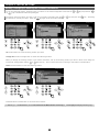
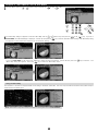
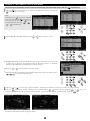
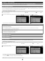
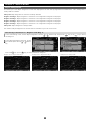
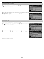
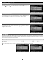
Ⅳ . Slewing to an Object in SCOPE MODE
Once the star alignment is completed in Section III, choose a celestial object to which you want to slew. You can look for objects like nebulae
and star clusters on the star charts of the STAR BOOK TEN to choose what you want to observe. Here, the Great Nebula, M42 in Orion, the
Hunter is shown as a target.
1
2
Press the
key to access the "Messier Object" database.
Select M42 with the
or
direction key. Or, enter directly 4→2 in succession. *1 *2 *3
*1: Objects marked with ◎ are available for observing.
If you choose an object with no ◎ mark, the message “Unable to GO below
horizon!” is displayed as shown below. Information about the object follows but you cannot slew to it.
1
2
*1
3
*2: Using the
or
zoom key will shift the courser on the screen with every five lines.
*3: The numerical keys allow to enter directly by number.
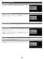
3
Press either the
key or the
direction key to advance the screen. The dialog box
appears, and confirms to proceed to the Go-To slewing. Press the
To stop, shift the cursor to Cancel with the
(or
or
key to start.
direction key and press the
) key. The dialog box disappears and you are ready to choose another.
If you discontinue the Go-To slewing, press the
key.
The telescope starts moving toward the target.
The telescope arrives at the target.
The Go-To slewing finishes with ringing the chimes.
32
53
Chapter 4 AUTOMATIC GOTO SLEWING
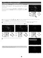
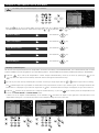
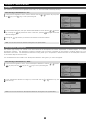
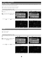
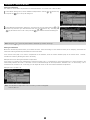
Ⅴ . Slewing to an Object in CHART MODE
The Go-To slewing in CHART MODE works in the same way as you did in SCOPE MODE .
Additionally, scrolling the star chart allows you to select any object as a target and
automatically slew your telescope to it. Here, the Great Nebula, M42 in Orion, the Hunter is
shown as a target.
Make sure the star chart is displayed in CHART MODE . If in SCOPE MODE , press the
key
to switch over the screen to CHART MODE . The screen will be highlighted in blue at its top and
bottom portions.
1
2
3
3
Scroll the star chart with the
Using the
or
•
•
•
direction keys so that M42 comes near to the center in the target circles.
zoom key at the same time will quickly facilitate this process.
Zooming in the star chart allows you to make slower movements of the star chart with the
Place M42 within the target circles. Then, bring it to the center and press the
•
•
•
direction keys.
key.
1
2
The dialog box will appear and confirm that you want Go-To slewing
Note: The dialog box will not appear on the screen if the “Go-To Message” is set to off.
In this case, the Go-To slewing starts at once.
33
53
Chapter 4 AUTOMATIC GOTO SLEWING
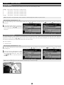
4
The Go-To slewing finishes with ringing the chimes. Pressing the
key will start slewing
the telescope to the target.
When you call up M42 from “Object Menu” in CHART MODE , the interactive dialog appears
on the screen. Choose OK and then press the
key, M42 will appear in the center of the
star chart as the target.
If you choose Cancel with the
•
or direction key and then press the
key, the Go-
To slewing will be discontinued. At the same time the screen changes to SCOPE MODE and
shows the area of the star chart where the telescope is pointing on its way to the target.
34
Chapter 4 AUTOMATIC GOTO SLEWING
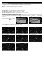
Ⅵ . Slewing to an Object with Command Keys
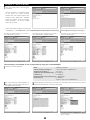
The STAR BOOK TEN has command keys to allow direct access to each list of celestial objects in the database.
This choice displays a list of planets in the solar system (Mercury, Venus, Mars, Jupiter, Saturn, Uranus, Neptune and a dwarfplanet Pluto) as well as the sun and moon.
This displays a compiled list of well-known n ebulae, star clusters and deep-sky galaxies.
Catalogs
This displays a complete list of Messier objects.
This displays a complete list of objects in the NGC and IC catalogs. Refer to an example of using the NGC/IC key on
page 43.
This displays a compiled list of bright and named fixed stars from the SAO catalog.
35
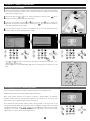
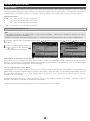
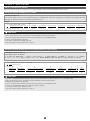
Chapter 4 AUTOMATIC GOTO SLEWING
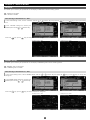
Moon Map
The “Moon Map “dialog box appears on the screen if you press the
key a little longer. The telescope can be pointed at the major "seas"
and geographical formations on the surface of the moon.
Note:
• The moon is displayed based on a simplified description of the age and map of the moon, but the moon seen on the screen may differ slightly
from the real one.
• The moon is relatively a very shining object and it may be so bright that your eye will tire with long observation. Therefore, it is advisable to
use a moon filter and the like for observing to reduce the brightness.
Calling up the Moon Map directly
1
2
Instant Display of the Moon Map: The “Moon Map “dialog box appears on the screen if you press the
key a little longer in both SCOPE
MODE and CHART MODE .
The “GOTO” dialog box will appear if the screen is in SCOPE MODE .
Message”. Choose OK and press the
The dialog box is displayed regardless of the setting of “GOTO
key to start the automatic Go-To slewing. The “Moon Map” dialog box appears on the screen
when the automatic slewing is completed. Be aware of the motion of your telescope.
To leave the dialog box, choose CANCEL with the
key or the
or
direction keys and press the
key, or pressing either the
direction
key to return to the previous screen.
If you use CHART MODE on the screen, the “SELECT?” dialog box will be displayed. Choose OK and press the
key to advance. The
“Moon Map” dialog box appears.
To leave the dialog box, choose CANCEL with the
the
or
direction key and press the
key, or press either the
direction key or
key to return to the previous screen.
1
2
Press a Little Longer.
Calling up the Moon Map from "Object Menu"
1
2
Before you begin, confirm that the “GOTO Message” is set to ON with the use of SCOPE MODE. Press the
Select “Sun Moon Planet” from the list with the
or
direction keys and press the
(or the
box.
1
2
36
key to call up the “Object Menu".
) key to move down to the subsidiary dialog
Chapter 4 AUTOMATIC GOTO SLEWING
3
Choose "Moon" with the
4
The "Moon Map" dialog box appears and choose "Moon Map" with the
or
direction key and press the
(or the
or
SCOPE MODE, the "GOTO Message" is displayed. Choose OK and press the
) key.
direction keys and press the
(or the
) key. If you are in
key to start the automatic Go-To slewing. The "Moon Map" dialog
box appears on the screen with completion of the automatic slewing.
If you use CHART MODE on the screen, the “SELECT?” dialog box will be displayed. Choose OK and press the
“Moon Map” dialog box appears. Press the
key to advance. The
key to leave the “Moon Map” menu.
Using the Moon Map
The orientation of the moon is displayed based on the setting in alt-azimuth or RA-DEC. The moon map enclosed with the black frame (frame mode) as
shown below is the default option.
Note: The direction keys are linked to the motor's driving directions in SCOPE MODE .
37
Chapter 4 AUTOMATIC GOTO SLEWING
Descriptions of Moon Map Screens
Screen 1: Changing the Size and Orientation of the Moon Map
Item
①
②
①
③
②
④
③
⑤
⑥
Description
Key Mirror-reversed left and right
Key Mirror-revered upside-down
Key Rotate upside-down (180 degrees)
Key Rotate counterclockwise
Key Return
Key Rotate clockwise
Keys for scrolling
⑯
⑦
⑧
⑰
⑨
⑩
④
⑤
⑱
⑥
⑪
⑫
⑦
⑪
⑨
⑩
③
⑬
⑮
⑭
②
Key Left Key moves the moon map right hand side.
Key Right Key moves the moon map left hand side.
Key Zoom In Key
Zooming in the moon map will
Key Zoom Out Key show you details of the location.
Key This switches the moon map to be movable or
immovable when pressed.
⑭
Key This allows you to leave the moon map.
⑫
⑧
Key Down Key moves the moon map upward.
⑬
⑮
①
Key Up Key moves the moon map downward.
Key This is used to choose your destination.
⑯
The name of a place that comes to the nearest to the center of the telescope's
field of view (or the center of the shown mapped area) is indicated.
⑰
The moon map is movable if it is enclosed with the black frame. (frame mode)
The list of the location names on the moon surface is displayed on the
right side of the screen.
⑱
The marks in front of the names of places stand for the following geographical
features.
Capital letter = Mare, Basin and Sinus
Small letter = Mountain Range, Terrace and Rill
Number = Crater
The above keys are linked to directions of the drive motors in
SCOPE MODE.
Screen 2: Indicating a Place on the Moon Map
You can choose a place you want to observe from the list of the location
on the moon surface.
Item
Description
①
Key This switches the moon map between frame mode
or not frame mode.
②
Key This allows you to leave the moon map.
③
Key This is used to choose your destination.
Keys for scrolling the cursor on the list of the location names.
④
⑧
Key Down Key moves the cursor downward.
⑥
Key Left Key cancels the current choice and moves
the screen a step back.
⑦
Key Right Key allows entering your choice
④
⑧
⑥
⑦
⑤
①
②
③
38
Key Up Key moves the cursor upward.
⑤
The moon map is immovable with the direction keys when it is not enclosed
with the black frame.
Chapter 4 AUTOMATIC GOTO SLEWING
Zooming In, Zooming Out and Scrolling the Moon Map (Refer to Screen 1)
1
2
Confirm that the moon map is in the frame mode. If not, press the
key to switch to the frame mode. The zoom keys enlarge or
reduce the size of the moon map as you press either the up or down key. Zooming in the moon map will display more details of the site.
The moon map can be scrolled up and down and left and right with the direction keys.
1
2
The moon map can be shifted up and down or left and right in the range of about 0.6 degrees radius from the center of the moon (1.35 times of
the size of the moon exactly) regardless of the MODE chosen. Location names may not appear if the moon map is zoomed in too far.
You can scroll the list of the terrain names one by one with the up and down direction keys if the frame mode is not selected. In this option, the
STAR BOOK TEN screen is not linked with the SXP mount and scrolls can be done smoothly and quickly. The zoom keys, reverse and rotation of
the moon map are inoperative in this mode.
Reversing and/or Rotating the Moon Map (Refer to Screen 1)
You can change the orientation of the moon map in accordance with the orientation of your view through your telescope. Display the moon map
in the frame mode by pressing the
key.
Mirror-reversed Left and Right Moon Map
The moon map can be switched from/to the mirror-reversed left and right image to/from the ordinary image orientation with press of the
key.
The mirror-reversed left and right image symbol on the bar information of the moon map is highlighted in green if you choose this option. It functions
along with the inverting image and rotating
functions.
Ordinary image orientation
Switching to a Mirror-reversed Left and Right image
Mirror-reversed Upside-down Moon Map
The moon map can be switched from/to the mirror-reversed upside-down image to/from the ordinary image orientation with press of the
key.
The mirror-reversed upside-down image symbol on the bar information of the moon map is highlighted in green if you choose this option. It functions
along with the inverting image and rotating functions.
Ordinary image orientation
39
Switching to a Mirror-reversed Upside-down image
Chapter 4 AUTOMATIC GOTO SLEWING
Inverted (180-degree rotated) Moon Map
The moon map can be switched from/to the inverted image to/from the ordinary image orientation with press of the
key. The inverted image
symbol on the bar information of the moon map is highlighted in green if you choose this option. It functions along with the mirror-reversed image
and rotating functions.
Ordinary image orientation
Switching to a Mirror-reversed Upside-down image
Rotating the Moon Map Clockwise or Counterclockwise
The moon map can be rotated voluntarily with the selection of the
and the
or
key. The
key is used to rotate the moon map counterclockwise
key is used to rotate it clockwise. The rotated moon map is returned to the initial image orientation if the
is pressed. The word
“Rotate” on the bar information of the moon map is highlighted in green if you choose this option. It functions along with the inverting and mirrorreversed image functions.
Ordinary image orientation
Voluntary rotated image
Go-To Slewing
The Go-To slewing to geographical features of the moon's surface is available in both SCOPE
MODE and CHART MODE by choosing the name of the location from the list or by choosing
places marked in numbers or letters on the moon map.
Pressing the
key will switch the moon map to the non frame mode so that you can select
the target from the name list of the locations on right side of the moon map.
Scrolling and
zooming of the moon map are disabled during this mode.
Note: Names marked ◎ are available for Go-To slewing as they are located above the horizon
but the terminator in phases of the moon is not considered.
As soon as you enter the moon map, it appears in frame mode. In SCOPE MODE , select a place
you want to view on the moon map with using the zoom and direction keys. Mare Serenitatis
(Sea of Serenity) is a target here by way of example. Zooming in the moon map reveals detailed
geographical features of the moon's surface.
In SCOPE MODE , the movement of your telescope is linked with the displayed moon map. The telescope may occasionally bring you to the object
that you are targeting without starting the Go-To slewing.
The target is highlighted in red if it comes near the center of the moon map. Pressing the
slew the telescope to Mare Serenitatis (Sea of Serenity). Choose “OK” and press the
key will call up the dialog box to ask if you want to
Key to proceed to the Go-To slewing. As soon as the
Go-To slewing finishes, the moon map around
Mare Serenitatis is displayed.
To stop the Go-To slewing, press the direction key
or
or
to choose “Cancel” and press the
the moon map chosen just before Go-To slewing. To leave the moon map press the
40
Key.
key. The screen is turned back to
Chapter 4 AUTOMATIC GOTO SLEWING
In CHART MODE , select a place you want to view on the moon map by scrolling and zooming
with the direction keys and zoom keys. Copernicus crater is a target here by way of example.
The list of location names on the moon map tracks the terrain as you move the moon map.
The target is highlighted in red if it comes near the center of the moon map. Pressing the
key
will call up the dialog box to ask if you want to slew the telescope to Copernicus crater.
Choose OK and press the
Key to proceed to the Go-To slewing. The screen changes to SCOPE MODE instantaneously.
Note:
• The list of location names of the moon (as of November 2011)
• Craters are displayed as numbers from 1 to 115.
• Sea (Mare), lake (Lacus), marsh (Palus) and bay (Sinus) are displayed in capital letters.
• Mountain, rille, scarp and valley are displayed in small letters.
41
Chapter 4 AUTOMATIC GOTO SLEWING
INDEX
Craters
Seas, Ocean, Bays, Lakes and Marsh
Albategnius
045
Geminus
057
Posidonius
013
Mare Australe (Southern Sea)
O
Alphonsus
008
Goclenius
061
Ptolemaeus
007
Mare Crisium (Sea of Crises)
E
Archimedes
011
Goldschmidt
114
Purbach
073
Mare Fecunditatis (Sea of Fertility)
H
028
Pythagoras
112
Mare Frigoris (Sea of Cold)
A
Aristarchus
010 Grimaldi
Aristillus
034
Guericke
043
Rabbi Levi
068
Mare Humboldtianum (Humbolt Sea)
L
Aristotle
012
Gutenberg
031
Regiomontanus
074
Mare Humorum (Sea of Moisture)
I
Arzachel
009
Hainzel
088
Reinhold
038
Mare Imbriun (Sea of Rain)
B
Atlas
055
Harpalus
111
Riccioli
098
Mare Nectaris (Sea of Nectar)
K
Autolycus
035
Hedin
100
Römer
032
Mare Nubium (Sea of Clouds)
J
Billy
097
Hercules
054
Russell
107
Mare Orientale (Eastern Sea)
N
Blancanus
080
Hevelius
099
Santbech
063
Mare Serenitatis (Sea of Serenity)
C
Boscovich
046
Julius Caesar
047
Scheiner
084
Mare Smythii (Sea of Smith)
M
Briggs
108
Kepler
029
Schickard
026
Mare Tranquillitatis (Sea of Tranquillity)
D
Bullialdus
030
Kraft
103
Schiller
090
Mare Vaporum (Sea of Vapors)
G
Burg
051
Krasnov
095
Seleucus
104
Oceans Procellarum (Ocean of Storm)
F
Campanus
085
Lagrange
091
Sharp
110
Lacus Mortis (Lake of the Dead)
P
Capuanus
087
Lamarck
092
Snellius
065
Lacus Somniorum (Lake of Dreams)
Q
Cardnus
102
Lambert
037
Stadius
004
Lacus Temporis
R
Cassini
033
Landberg
039
Stevinus
066
Sinus Iridum (Rainbow Bay)
S
Catharina
021
Langrenus
015
Stöffler
024
Sinus Roris (Bay of Dew)
T
Clavius
006
Longomontanus 083
Struve
106
Sinus Aestuum (Seething Bay)
U
Cleomedes
014
Macrobius
059
Taruntius
060
Sinus Medii (Central Bay)
V
Columbus
062
Maginus
078
Theophilus
019
Sinus Amoris
W
Copernicus
001
Mairan
109
Timocharis
036
Palus Epidemiarum
X
Crüger
096
Manilius
048
Tycho
002
Palus Putredinis (Marsh of Decay)
Y
Curtius
077
Manzinus
076
Vendelinus
016
Cyrillus
020
Marius
101
Vlacq
071
Mountains, Scarps, Valleys and Rills
Darwin
094
Massala
056
W. Bond
115
Montes Alpes (Alps Mountains)
a
De La Rue
052
Maurolycus
023
Walter
075
Montes Apenninus (Apennine Mountains)
b
Eddington
105
Mee
089
Wilhelm
082
Montes Carpatus (Carpathian Mountains)
c
Endymion
053
Mercator
086
Zagut
067
Montes Caucasus (Caucasian Mountains)
f
Eratosthenes
003
Mersenius
093
Montes Haemus (Haemus Mountains)
g
Eudoxus
050
Metius
069
Montes Jura (Jura Mountains)
e
Fabricius
070
Moretus
079
Montes Pyrenaeus (Pyrenee Mountains)
d
Faraday
025
Parry
042
Montes Taurus (Taurus Mountains)
h
Flammarion
044
Petavius
017
Rupes Altai (Altai Scarp)
j
Fra Mauro
041
Philolaus
113
Rupes Recta (Straight Wall)
i
Fracastorius
064
Piccolomini
022
Rima Ariadaeus
l
Furnerius
018
Pitatus
081
Rima Hyginus (Hyginus Cleft)
m
Gambert
040
Pitiscus
072
Rima Sharp
o
Gassendi
027
Plato
005
Vallis Rheita (Rheita Valley)
k
Gauss
058
Pliny
049
Vallis Schroteri (Schroter's Valley)
n
42
Chapter 4 AUTOMATIC GOTO SLEWING
The following is an example on how to slew to NGC224 (M31, the Andromeda galaxy) with the
1
command key.
Press the key to access the lists of objects in the NGC or IC catalog. Pressing the
key will switch the catalogs.
Note:
Switching by the
key is only available
when it is used with the
command key.
The switching function of the not applicable with the other
•
2
key is
•
•
command keys.
Choose NGC224 in the NGC catalog with the
or
direction key.
*1 *2 *3
marked objects can be seen above the horizon of your observing site. If you choose
*1 The
an object with no mark, the message “Unable to GO below horizon!” is displayed.
Information about the object is displayed, but you cannot slew to it.
* 2 Using the
or
zoom key will shift the curser 5 lines.
available to call up Messier, NGC and IC objects by number.
* 3 The numerical keysby are
using the numerical keys.
3
Press the or
Press the
Enter
direction key to choose NGC224. The dialog box appears to confirm to proceed to the Go-To slewing.
key to start. To stop, shift the cursor to Cancel with the
or
direction key and press the
(or
dialog box disappears and you are ready to choose another. If you discontinue the Go-To slewing itself, press the key.
The telescope starts moving toward the target object.
The telescope arrives at the target object.
The Go-To slewing finishes with ringing the chimes.
43
) key. The
Chapter 4 AUTOMATIC GOTO SLEWING
This displays all of the celestial objects in the database.
Press the
key to call up “Object Menu” which includes each list of Messier objects, NGC/IC objects, planets, the sun, the moon,
constellations, fixed stars and more. Select the list using the
or
key and press
(or
) key.
Messier Object
This equals the
key.
NGC / IC Object
This equals the
key.
Sun Moon Planet
This equals the
key.
Star
This equals the key.
Named Object
This equals the key.
Recently Located Objects
The 20 most recent objects selected from the “Object Menu” are stored in the memory of the STAR BOOK TEN. This is saved after the power is turned
off and is available as your Go-To together for your next observing session. The stored data can be erased by initializing the memory in "System Menu".
1
2
Press the key to call up the “Object Menu”. Select “Object Located Recently” at the top of the list by pressing the (or the
) key.The moon map can be scrolled up and down and left and right with the direction keys.
Up to 20 of your most recently viewed objects are listed. Choose your target object with the
The
direction keys for Go-To slewing.
marked objects are only available for observation if they are above the horizon at your observing site. A message “Unable to GO
below horizon” is displayed if you choose an object with no
3
or
Press the continue the
mark. Information about the object is displayed, but you cannot slew to it.
direction key to leave the list of “Objects Located Recently”, or press the key to instantly close the “Object Menu” and
CHART MODE
or
SCOPE MODE
screen.
If there is no list of "Objects Located Recently” to be available, the mark does not appear on the right side of the description in the
“Object Menu” dialog box. You cannot step down to the subsequent dialog box if this is the case.
1
2
44
3
Chapter 4 AUTOMATIC GOTO SLEWING
Constellation
This identifies locations of all 88 constellations.
letters of Greek alphabet) in the constellation.
1
2
3
Additionally, it allows you to slew to any stars labeled with a Bayer designation (the
Call up “Object Menu” and choose “Constellation” with the
or
direction key.
Press the
(or
)key to access a list of 88
constellations.
Choose the constellation you want to view with the
or
key and press
(or
) key.
Press the key to start the Go-To slewing. To stop, shift the cursor to Cancel with the or direction key and press the
The dialog box disappears and you are ready to choose another. If you discontinue the Go-To slewing itself, press the
1
4
(or
)
key.
Stars shown in constellations can be identified by a Bayer designation which is assigned to
a star.
key.
2
4
Here, Gamma Monoceros (the Unicorn) is chosen as an example.
5
Choose a star you want to slew to with the
or
key and press the
45
(or
)key.
5
Chapter 4 AUTOMATIC GOTO SLEWING
Calling up Bayer Designation Directly
The list of the Bayer designation appears on the screen if you press the
key a little
longer
長押し
Choose a Bayer designation in the entry dialog box with the
the
(or
or
direction key. Press
)key to display a star which have a Greek-letter designation.
Coordinates
This allows slewing to objects by entering celestial coordinates or altitude/azimuth directions.
1
2
3
Call up “Object Menu” and choose “Coordinates” with the
or
direction key. Press the
(or
)key to access the entry dialog
box.
Choose “RADEC” or “AltAz” with the
or
key. Enter a numerical value with the
Press the
or
direction key and advance the cursor to an available entry space with the
key and press the
or direction
key.
key to start the Go-To slewing. To stop, shift the cursor to Cancel with the
or
direction key and press the
(or
)
key. The entry dialog box disappears.
1
2
If you enter a wrong number or your target is below the horizon, you will be alerted by a message on the screen.
The wrong umber is entered.
The target is below the horizon.
46
3
Chapter 4 AUTOMATIC GOTO SLEWING
Comet
This allows slewing to comets. The orbital elements of the comet McNaught (2009 R1) are shown as an example.
Entering the Orbital Elements of the Comet
STAR BOOK TEN allows you to enter orbital elements of up to 10 comets for Go-To slewing.
You can access the orbital elements of
comets from commercially available astronomy magazines, internet websites and so forth. Use the most recent ones to prevent inaccurate
slewing to the comet and to diminish tracking errors.
1
2
3
Call up “Object Menu” and choose “Comet” with the or direction key. Press the
With the
or
Press the
(or
)key to access the entry dialog box.
direction key, move the courser to an available entry space where no comet names are set. (The third line is chosen here.)
key to display the “New Object” dialog box and move the cursor to an available entry space with the
Enter the name of the comet and its orbital elements by alphabet and number with the
1
•
or
direction key.
2
The orbital elements of the comet McNaught (2009 R1)
Code Name
2009 R1
Time of Pericenter Passage (T)
2010 / 6 / 2.67841 TT
Argument of Pericenter (ω)
130.70095
Longitude of the Ascending Node (Ω)
322.62188
Inclination (i )
77.03226
Minimum Distance from Pericenter (q)
0.4050263 AU
Eccentricity (e)
1.0003431
direction key.
3
When figuring the decimal fraction for orbital elements, the resulting
number must have three spaces before the decimal and the number
after the decimal is determined by the number of spaces available.
Round off at that point.
EPOCH = June 13.0, 2010
Note : Use the
(Here, the
4
Press the
or
•
zoom key to shift the cursor in the vertical direction while you enter alphabets and numbers.
direction keys are not allocated for moving the cursor.)
key to complete the entry. Then, press the
key again to leave this
menu.
If a wrong number is entered, the item for the entry will be highlighted in red to alert you.
47
4
Chapter 4 AUTOMATIC GOTO SLEWING
Entering the Orbital Elements of the Comet
OK: Choose OK to slew the telescope to the comet you chose.
Press the
or
•
key to start the Go-To slewing. To stop, shift the cursor to Cancel with the
direction key and press the
you are ready to choose another.
(or
) key. The entry dialog box disappears and
Change Data : Choose “Change Data” to rewrite the orbital elements.
To change the parameters of the set orbital elements, display the entry dialog box and choose “Change Data” with the
key. Then, press the
key to change the parameters.
or
direction
Delete : Choose “Delete” to clear the orbital elements.
To delete the entered orbital elements of a comet, display the entry dialog box and choose “Delete” with the
press the
key.
or
direction key. Then,
Note: If your STAR BOOK TEN is connected to a PC with LAN, the orbital elements can be input, changed or deleted through the PC.
48
Chapter 4 AUTOMATIC GOTO SLEWING
Satellite (Artificial Satellite)
This allows observing a satellite pass.
Entering the Orbital Elements of the Satellite
STAR BOOK TEN allows you to enter orbital elements of up to 10 satellites for Go-To slewing. You can access the orbital elements of satellites
from commercially available astronomy magazines and internet websites. Use the most recent ones to prevent inaccurate slewing to the satellite
and to diminish tracking errors. Besides, it is very important to set your STAR BOOK TEN to be punctual to the second.
1
2
3
Call up “Object Menu” and choose “Satellite” with the
With the
or
Press the
or
direction key. Press the
(or
)key to access the entry dialog box.
direction key, move the cursor to an entry space where no satellite names are set. (The second line is chosen here.)
key to display the “New Object” dialog box and move the cursor to an available entry space with the
Enter the name of the satellite and its orbital elements by alphabet and number with the
•
or
direction key.
direction key.
.
1
Note : Use the
(The
•
or
2
3
zoom key to shift the cursor in the vertical direction while you enter alphabets and numbers.
direction keys are not allocated for moving the cursor.)
The orbital elements of the weather satellite NOAA is shown in TLE format as an example.
1 04793U 70106A 10136.02215887 -.00000031 00000-0 10000-3 0 5176
2 04793 102.0931 137.9363 0031946 163.7080 196.5027 12.53938386804630
The orbital elements of the satellites are typically represented in a format that is called “Two Line Elements”. Sampling parameters related
to the orbital elements of the satellite and its name only from the TLE format and enter them into the STAR BOOK TEN.
① Name of Satellite
The TLE format consists of the following structure.
① ② ③ ② Satellite Number
③ International Designation
④ Epoch Year & Day Fraction
④ ⑤ ⑥ ⑦ ⑧ ⑨
⑤ 1st derivative of Mean Motion
⑥ 2nd derivative of Mean Motion
NOAA 1
1 04793U 70106A
⑦ Radiation Pressure Coefficient
10136.02215887 -.00000031 00000-0 10000-3 0 5176
⑧ Ephemeris Type
⑨ Element Number & Checksum
2 04793 102.0931 137.9363 0031946 163.7080 196.5027 12.53938386804630
⑩ Inclination
⑪ Right Ascension of the Ascending Node
⑫ Eccentricity (decimal place)
② ⑩ ⑪ ⑫ ⑬ ⑭ ⑮ ⑯
⑬ Argument of Perigee
⑭ Mean Anomaly
⑮ Mean Motion
⑯ Revolution Number at Epoch & Checksum
Of the above parameters in TLE format, ① ④ ⑤ ⑩ ⑪ ⑫ ⑬ ⑭ ⑮ are utilized for determining orbital elements. (The parameters ② ③ ⑥ ⑦ ⑧ ⑨ ⑯
are not necessary for the STAR BOOK TEN.) The number after the decimal is determined by the number of spaces available and round off
at that point.
49
Chapter 4 AUTOMATIC GOTO SLEWING
4
Press the
key to complete the entry. Then, press the
key again to leave this menu. If a wrong number is entered, the item for the
entry will be highlighted in red to alert you.
Setting, Changing or Deleting the Orbital Elements of the Satellite
OK: Choose OK to slew the telescope to the satellite you chose.
Press the
(or
key to start the Go-To slewing. To stop, shift the cursor to Cancel with the
• ) direction key and press the
(or
) key. The entry dialog box disappears
and you are ready to choose another.
3
Change Data : Choose “Change Data” to rewrite the orbital elements.
To change the parameters of the set orbital elements, display the entry dialog box and choose “Change Data” with the
Then, press the
or
direction key.
key to change the
parameters.
Delete : Choose “Delete” to clear the orbital elements.
To delete the parameters of the set orbital elements, display the entry dialog box and choose “Delete” with the
press the
key.
50
or
direction key. Then,
Chapter 4 AUTOMATIC GOTO SLEWING
User Coordinates
STAR BOOK TEN allows you to add 10 new objects to the database by using celestial coordinates.
terrestrial objects with altitude and azimuth for terrestrial objects.
azimuth setting.
1
2
Call up “Object Menu” and choose “User Coordinates” with the
It is possible to define and store
The tracking will be off if you choose an object in the altitude and
or
direction key. Press the
(or
) key to access the entry dialog
box.
With the
or
Press the
direction key, move the cursor to an available entry space where no user coordinates are set. (The third line is chosen here.)
key to display the “New Object” dialog box to make your option.
1
2
Setting a Point by Coordinates
In the "New Object" dialog box of "User Coordinates", the position that your telescope is pointing is indicated in RA and DEC and it can be
stored in the database. For terrestrial objects, bring the cursor to "RADEC" with the
with the
or
direction key.
or
zoom key to switch the indication to "AltAz"
Access the "User Coordinates" dialog box and move the cursor to an available entry space
with the
•
direction key.
Press the
key to display the "New Object" dialog box and move the cursor to an available
entry space with the
•
•
•
direction key.
Enter the name and its location of the point by alphabet and number with the
or
direction key.
Press the key to complete the entry. Then, press the again to leave this menu.
Note: Use the
or
zoom key to shift the cursor in the vertical direction while you enter
alphabets and numbers. (The
•
direction keys are not allocated for moving the cursor.)
If a wrong number is entered, the item for the entry will be highlighted in red color to alert you.
Slewing to the Set Point, Changing or Deleting the Point
Access the “User Coordinates” dialog box and move the cursor to the point you slew to with the
Press the
(or
)key to display the entry dialog box. Choose OK or “Change Data” or
“Cancel” at your option with the
or
direction key.
OK : Choose OK to slew the telescope to the point you chose.
Press the
(or
•
key to start the Go-To slewing. To stop, shift the cursor to Cancel with the
)direction key and press the
and you are ready to choose another.
(or
) key. The entry dialog box disappears
51
•
direction key.
Chapter 4 AUTOMATIC GOTO SLEWING
Change Data: Choose “Change Data” to rewrite the set points.
To change the set point, display the entry dialog box and choose “Change Data” with the
direction key. Then, press the
or
key.
Delete: Choose “Delete” to clear the orbital elements
To delete the set point, display the entry dialog box and choose “Delete” with the
or
direction key. Then, press the
key.
Note: If your STAR BOOK TEN is connected to a PC with LAN, the orbital elements can be input, changed or deleted through the PC.
Home Position
Allows you to return the telescope to the initial setting position without loosening the RA and DEC lock levers on the mount, and assures
that the mount retains all the alignments. The telescope slews back to the initial setting position where the telescope tube is level and
points to the west
Note: The telescope may not return to the initial setting position if the lock levers are loosened during observation
1
Call up “Object Menu” and choose “Home Position” with the
2
Press the
(or
or
direction key.
)key and the dialog box appears to confirm if you slew the telescope to
the home position. Choose OK or Cancel with the
or
direction key and press the
key.
52
Chapter 5 APPLICATION
Ⅰ . How to Use the Polar Axis Scope
What is Polar Axis Scope?
After setting up the telescope, locate the SXP mount so that its R.A. axis points toward the north celestial pole if you use the telescope in the
Northern hemisphere. If your intention is not to take lengthy astrophotography, you don't need to align the R.A. axis to the celestial pole
precisely. A rough setting will work well for visual observation. While looking for the polar star, locate the mount so that it faces toward the
north and the elevation of the R.A. axis matches the latitude of your observing site.
CAUTION
* Inaccurate polar alignment could result in trailed stars and field rotation in your imaging device.
* It is not possible to use the SXP mount in the north latitude over 70 degrees and in the south latitude over 70 degrees.
Polar Axis Scope Components
Time Graduation Circle
(10-minute increments)
Eyepiece of the Polar Axis Scope
Time Meridian Indicator
Eyepiece
Knurled Ring
(for focusing)
Meridian Offset Scale
(Between E20 and W20
at 5-degree increments)
Date Graduation Circle
(2-day increments)
Line Mark
Water Level
Polar Alignment in the Northern Hemisphere
1
Set up the telescope on a flat and hard ground where you can see Polaris in the sky. Point
2
Take off the declination cap and polar axis cap.
the polar axis of the SXP mount in the direction of north as shown in the figure. Adjust the
tripod legs so that will the tripod is as level as possible.
twisting counter-clockwise.
These caps can be removed readily by
Declination Cap
Polar Axis Cap
3
Turn on the power switch of the mount and advance the initial settings until the telescope's
home position screen appears on the screen of the STAR BOOK TEN.
53
Celestial Pole
To
wa
Polar Axis
rd
th
e
No
rth
Chapter 5 APPLICATION
4
While looking into the opening of the polar axis scope on the declination body, turn the
5
Loosen the altitude clamp lever and turn the altitude adjustment knob so that the indicator of
declination body with the
or
scope can be seen in the opening.
direction key so that the objective lens of the polar axis
Opening
the altitude scale fits the latitude of your observing site. The mount is set at an altitude of
approximately 35 degrees at Vixen's factory.
Altitude Scale
Reading Guide
Azimuth Adjustment Knob
Azimuth Clamp Lever
6
7
8
9
While looking into the eyepiece of the polar axis scope, turn the focus ring until the reticle is in focus. Hold the eyepiece tube with the
other hand while you turn the focus ring.
Adjust the brightness of the illuminator for the polar axis scope so that the reticle is dimly illuminated.
Turn the time graduation circle by holding both sides of the bubble level so that the bubble is brought into the center of the level marks.
Check the difference between standard time meridian of your region (or country) and your observing site on a map of the area or by using a
GPS system.
6
8
Line Marks
9
Date Graduation Circle
Time Meridian
Indicator
Bubble
Eyepiece Knurled
Ring
If the observing site is east of standard time meridian, rotate the time-meridian offset scale in the direction as indicated by "E".
If the
observing site is west of standard time meridian, rotate the time-meridian offset scale in the direction as indicated by "W". Turn the timemeridian offset scale while holding the eyepiece tube with the other hand.
Example 1:
If you observe in Okinawa Japan, which is located at 127 degrees longitude, you need to offset by 8 degrees in the direction of W from the
central meridian of the Japan Standard Time after the calibration.
Example 2:
If you observe in Boston, MA, which is located at 71 degrees longitude, you need to offset by 4 degrees in the direction of E from the
central meridian of the Eastern Standard Time after the calibration.
Example 3:
If you observe in Dallas, TX, which is located at 97 degrees longitude, you need to offset by 7 degrees in the direction of W from the central
meridian of the Central Standard Time after the calibration.
Example 4:
If you observe in Los Angeles, which is located at 118 degrees longitude, you need to offset by 3 degrees in the direction of E from the
Central meridian of the Pacific Standard Time after the calibration.
54
Chapter 5 APPLICATION
10
Match the date graduation circle with your local observing time by rotating the polar axis scope. The figure below shows 21h 42m on
December 20th. The time graduation circle has a scale in 10-mimute increments, but you may set it as fine as one minute.
Eyepiece
21h42m
December 20h
11
While looking into the eyepiece of the polar axis scope, turn the azimuth adjustment knobs and the altitude adjustment knob alternately so
that Polaris comes to the position in the reticle as shown in the figure. Readjust the brightness of the reticle to be dimmer if necessary.
Note: The position of the celestial poles moves gradually each year due to precession.
According to this, the position of Polaris shifts every year.
Polaris
Precession
12
Unfastening one side of the azimuth adjustment knobs will allow fastening the knob on
the other side.
Azimuth Adjustment Knobs
13
Turn the altitude adjustment knob
Altitude Adjustment Knob
14
Tighten the azimuth adjustment knobs and altitude adjustment knob securely and complete the polar alignment.
55
Chapter 5 APPLICATION
Polar Alignment in the Southern Hemisphere
Octans is a constellation located near the south celestial pole and it can be used to align the Polarie in the southern hemisphere. Unlike
Polaris which is a bright 2nd magnitude star adjacent to the north celestial pole, Octans is made up of dark stars about 5th magnitude on
average. The nearest star to the south celestial pole is Sigma Octantis, which is one of four stars forming a trapezoid in Octans, visible at
5.5th magnitude. There are a few methods to locate inconspicuous Octans using the surrounding stars.
S m a l l M a g e l l a n i c C l ou d
HYDRUS
β
3
1
OCTANS
γ1
γ2
γ3
υ
τ
χ
σ
1
CE N TA U R U S
2
80
°
β
α
γ
MU S C A
C H A MA ELE ON
M ENSA
δ
70
CRUX
°
C A R IN A
VOL ANS
La rge Mag e l l a nic Cloud
DORADO
Note: The orientation of the Octanschanges depending on the season of year.
1. Directing to the Octans using Small Magellanic Cloud and the Southern Cross (Crux) as pointers
Draw an imaginary line between the center of Small Magellanic Cloud and Beta Crux and divide it at a ratio of one to two. You will find the
four stars of Octans at the divide.
2. Directing to the Octans using the arrangement of stars in the Southern Cross (Crux) as pointers
Draw an imaginary line straight through the two stars (Alpha and Beta Crux) of the Southern Cross making the vertical line of the cross toward
Small Magellanic Cloud. You will find the four stars of Octans at a place about 4.5 times extended from the span of the two stars.
3. Directing the Octans using Small Magellanic Cloud, Beta Hydrus and Gamma Octantis as pointers
If you cast your eyes a little toward Crux from Small Magellanic Cloud, you will see Beta Hydrus. Going southward from Beta Hydrus will find
you Gamma Octans which consists of a row of three stars. Continue on your eyes by the same distance toward the Southern Cross and you
will find the four stars of Octans.
56
Chapter 5 APPLICATION
The polar axis scope contains a reticle showing the relative positions of four stars near the southern celestial pole. The stars are Sigma, Tau,
Chi and Upsilon of Octans. Polar align the mount with these four stars but precession is not considered.
1
2
3
4
Set up the telescope in a flat and hard ground where you can see Octans in the sky. Point the polar axis of the SXP mount in the direction
5
While looking into the eyepiece of the polar axis scope, turn the
of south. Adjust the tripod legs so that the tripod is as level as possible.
Take off the declination cap and polar axis cap. These caps can be removed readily by twisting counter-clockwise.
Turn on the power switch of the mount and advance the initial settings until the telescope's
home position screen appears on the screen of the STAR BOOK TEN.
Refer to set up procedures 4 to 7 that are described for the use in the northern hemisphere.
azimuth adjustment screws and the altitude adjustment screw
χ
alternately so that the four stars of Octans comes into the field of
τ
view of the polar axis scope. Readjust the brightness of the reticle
to be dimmer if necessary.
υ
Octantis
6
Octantis four stars
σ
Magnitude
σ (Sigma)
5.5
χ (Chi)
5.2
τ (Tau)
5.6
υ (Upsilon)
5.7
β
γ3
γ2
Field of view of the
polar axis scope
While looking into the eyepiece of the polar axis scope, rotate the
polar axis scope so that the four stars of Octans comes to the
position in the reticle as shown in the figure.
Match with the orientation of the four stars
χ
σ
τ
υ
β
7
Match the form of the Octantis four stars on the reticle with
the four stars of Octans while looking through the polar axis
γ3
γ2
Match with each other
scope.
χ
σ
τ
υ
Note: The position of the celestial poles moves gradually each year due to precession. According to this, the pattern of Octans shifts every year.
57
Chapter 5 APPLICATION
Precise Polar Alignment (Drift Alignment)
If you align the mount with the provided polar axis scope correctly, the mount will be able maintain tracking celestial objects within the field
of view of your telescope's eyepiece. For astrophotography, it enables you to take exposures of 5 to 10 minutes with a telephoto lens of
200mm focal length or less.
However, if you want to take longer exposures than 10 minutes or use a telephoto lens of longer focal length than 200mm, more precise
polar alignment is required.
The following method of polar adjustment will be done by watching the movement of a bright star in the
eyepiece and it is called drift alignment.
CAUTION
Refrain from doing the star alignment with the STAR BOOK TEN if you need to perform the drift alignment. If the mount type is chosen
as "Equatorial mount without polar setting", the position information collected by the star alignment will be applied for the polar
alignment.
This will spoil the drift alignment as any drifts from the celestial pole are detected and corrected automatically.
Choose
"Equatorial mount with polar setting" to avoid these corrections. Also turn off the function of depressing atmospheric refractions.
Drift Alignment in the Northern Hemisphere
1
2
Align the mount to the north celestial pole by using the polar axis scope. This will save time during the process of drift alignment.
Align the Mount in Azimuth
Prepare an eyepiece with illuminated reticle (cross hairs) or you use a Vixen OR12.5mm with illuminated reticle. Choose a bright star
near the celestial equator and near the meridian, and put it in the filed of view of the eyepiece. Turn off the power switch of the mount
momentarily while looking into the eyepiece to see which direction the star moves. Confirm the west and rotate the eyepiece so that one
of the cross hairs is parallel to the east-west direction in the field of view. The figure on the right shows the directions of north, south,
east and west in the eyepiece according to a type of your telescope with or without a star diagonal.
South
(Inv e r t e d V ie w)
East
・
・
West
・
West
・
・
・
・
・
North
・
East
★
・
East
North
・
★
・
North
・
West
・
South
★
・
Look for south
in the sky
South
( Er e ct Vi e w )
( M i r r o r - R e ve r se Vi e w )
The following descriptions are based on a telescope without a star diagonal.
Drive the mount at sidereal rate and look into the eyepiece to monitor the drift motion of the star in the north-south direction.
If the star drifts north (i.e. moves down due to inverted view), move the mount to east in azimuth.
If the star drifts south (i.e. moves up due to inverted view), move the mount to west in azimuth.
Adjust the mount with the azimuth adjustment screws. Make appropriate adjustments to the polar axis to eliminate the drift.
Align the Mount in Altitude
Choose a bright star near celestial equator in east but not too low, and put it in the filed of view of the eyepiece. Turn off the power
switch of the mount momentarily while looking into the eyepiece to see in which direction the star moves. Confirm the west and rotate
the eyepiece so that one of the cross hairs is parallel to the east-west direction in the field of view. The figure on the right shows the
t
es
W
th
Ea
N
or
h
ut
So
★
・
h
ut
So
st
Ea
or
t
N
st
es
Ea
h
( Er e ct Vi e w )
ut
(Inv e r t e d V ie w)
So
th
★
・・
・
・
・
・
・
・
・
・
・
・
・
★
・
th
t
or
es
N
W
Look for east
in the sky
st
directions of north, south, east and west in the eyepiece according to a type of your telescope with or without a star diagonal.
W
3
( M i r r o r - R e ve r se Vi e w )
The following descriptions are based on a telescope without a star diagonal.
Drive the mount at sidereal rate and look into the eyepiece to monitor a drift motion of the star in the north-south direction.
If the star drifts south (i.e. moves toward the lower left due to inverted view), move the mount to low in altitude.
If the star drifts north (i.e. moves toward the upper right to inverted view), move the mount to high in altitude.
Adjust the mount with the altitude adjustment screws. Make appropriate adjustments to the polar axis to eliminate the drift.
58
Chapter 5 APPLICATION
Drift Alignment in the Southern Hemisphere
Align the mount to the south celestial pole by using the polar axis scope. It will save you a lot of time in the process of drift alignment
1
Align the Mount in Azimuth
Prepare an eyepiece with illuminated reticle (cross hairs) or you use a Vixen OR12.5mm with illuminated reticle.
Choose a bright star
near the celestial equator and near the meridian, and put it in the filed of view of the eyepiece. Turn off the power switch of the mount
momentarily while looking into the eyepiece to see which direction the star moves. Confirm the west and rotate the eyepiece so that one
of the cross hairs is parallel to the east-west direction in the field of view.
The following descriptions are based on a telescope without a star diagonal.
Drive the mount at sidereal rate and look into the eyepiece to monitor the drift motion of the star in the north-south direction.
If the star drifts south (i.e. moves down due to inverted view), move the mount to east in azimuth.
If the star drifts north (i.e. moves up due to inverted view), move the mount to west in azimuth.
Adjust the mount with the azimuth adjustment screws. Make appropriate adjustments to the polar axis to eliminate the drift.
2
Align the Mount in Altitude
Choose a bright star in east but not too low, and put it in the filed of view of the eyepiece.
Turn off the power switch of the mount
momentarily while looking into the eyepiece to see in which direction the star moves. Confirm the west and rotate the eyepiece so that
one of the cross hairs is parallel to the east-west direction in the field of view.
The following descriptions are based on a telescope without a star diagonal.
Drive the mount at sidereal rate and look into the eyepiece to monitor a drift motion of the star in the north-south direction.
If the star drifts south (i.e. moves toward the lower left due to inverted view), move the mount to low in altitude.
If the star drifts north (i.e. moves toward the upper right to inverted view), move the mount to high in altitude.
Adjust the mount with the altitude adjustment screws. Make appropriate adjustments to the polar axis to eliminate the drift.
Change the Altitude Setting on the SXP Mount
The SXP mount is set for use in the middle latitude zone (latitude of 35 degrees plus/minus 15 degrees) at Vixen's factory.
If your
observing site is lower or higher than the range of the middle latitude zone, you need to change the current altitude setting to match the
latitude of your observing site. The range of altitude adjustments is
divided into three positions (low, middle and high) between 0 degrees
1
2
3
4
Remove the optical tube and the counterweights from the mount.
High Latitude :
40 degrees up to 70 degrees
Middle Latitude :
20 degrees up to 40 degrees
Low latitude:
0 d e g r e e up to 30 degrees
Loosen the altitude clamp lever on one side of the mount body where no altitude scale is attached, and turn the altitude adjustment knob
so that the altitude of the mount comes to a position of 35 degrees. Then, tighten the altitude clamp lever.
Loosen a bolt beneath the altitude clamp
2
lever with the 5mm Allen wrench and remove it.
3
Loosen the altitude clamp lever while
holding the mount head with the other
Azimuth Adjustment Knob
5mm Allen wrench
hand so that the mount body is moved
slowly to high or low position in altitude.
Azimuth Clamp Lever
5
6
7
Move the mount to a position of 55 degrees in altitude if you use the mount in the range of high latitude.
Put back the bolt in place and tighten it
5
with the Allen wrench securely.
6
Loosen the altitude clamp lever again and
turn the altitude adjustment knob so that
5mm Allen wrench
the mount is set at the latitude of your
observing site.
8
Or move the mount to a
position of 15 degrees in altitude of you use the mount in the range of low latitude. Tighten the altitude clamp lever.
Azimuth Clamp Lever
Tighten the altitude clamp lever and the
setting is completed.
CAUTION
Never tilt the mount body quickly. It may result in damage or lead to injury.
59
Chapter 5 APPLICATION
Ⅱ . INITIAL CONFIGURATION (Main screen right after turning ON the power)
This allows you to choose the settings for various functions including time and location.
Use Last Mount Setting
This allows you to continue using the SXP mount with the same settings you used during your last observing session.
option, the STAR BOOK TEN retains its alignment data while the mount is powered off.
to start Go-To slewing and observing quickly without the routine alignment works.
If you choose this
When you use the mount next time, you will be able
The set t i n g i s d ef a u lte d to “ OF F ” .
1
2
In the “Initial Configuration” menu, choose “Use Last Mount Setting” with the or direction key and press the key (or the key)
to call up the dialog box.
In the “Use Last Mount Setting” dialog box, choose OK with the
or
direction key and press the key to advance.
1
2
If you return to the “Initial Configuration” menu from the “Solar Warning” screen, just press the key.
Important Note
To make the “Use Last Mount Setting” available, make sure to follow instructions below when you finish your observing session.
* Never move the telescope.
* Never loosen the lock clamps.
* Do not change the positions of equipment and instruments attached on the mount, and do not remove them from the mount.
* Do not remove the battery from the STAR BOOK TEN.
The following settings are not saved.
* The target just before turning off the power switch.
* Setting of the LCD adjustment (Initialized).
* Zoom level that is displayed on the screen.
Setting Local Time
Refer to Chapter 2 Initial Setting.
Setting Location
Refer to Chapter 2 Initial Setting.
LCD Adjustment
The brightness of the LCD screen can be adjusted from 0 to 20, i.e. “off to the brightest” divided by 20 steps.
The set t i n g i s d ef a u lte d to “ 1 5 ” .
1
2
In the “Initial Configuration” menu, choose “LCD Adjust” with the
the dialog box.
or
direction key and press the
In the “LCD Adjust” dialog box, enter your desired value between 0 and 20 by number with the
key will shift the cursor to OK.
1
The setting is returned to the default and not saved when you turn off the STAR BOOK TEN.
Ten, press the
key again to save and leave the dialog box.
You can also access the “LCD Adjust” dialog box from “System Menu”.
Note: Using the zoom key will shift the curser on the screen every five lines.
60
or
key (or the
key) to call up
direction key and pressing the
2
Chapter 5 APPLICATION
Night Vision
To maintain your night vision, avoid white light. The “Night Vision” mode of the SXP mount turns the screen from the bright “white color” to
gentle “red color”. You can use it together with the “LCD Adjust” for the best accommodation to your eyes.
The set t i n g i s d ef a u lte d to “ OF F ” .
1
In the “Initial Configuration” menu, choose “Night Vision” with the
2
Choose ON with the
press the
key (or the
screen.
or
or
key) to call up the dialog box.
direction key and press the
direction key and
key to activate the “Night Vision”
Examples of Night vision screens
Note: You can also access the “Night Vision” dialog box from “System Menu”.
Key LED Brightness
The brightness of the backlight LED for the keys can be adjusted from 0 to 20, i.e. “off to the brightest” divided by 20 steps.
The set t i n g i s d ef a u lte d to “ 1 5 ” .
1
In the “Initial Configuration” menu, choose “Key LED Brightness” with the or direction
2
In the “Key LED Brightness” dialog box, enter your desired value between 0 and 20 with the
key and press the key (or the key) to call up the dialog box.
or
key and pressing the
key will shift the cursor to OK.
The setting is returned to the default and not saved when you turn off the STAR BOOK TEN.
Then, press the
key again to save and leave the dialog box.
Note: You can also access the “Key LED Brightness” dialog box from “System Menu”.
61
Chapter 5 APPLICATION
Volume
The volume of the chimes can be adjusted from 0 to 20, i.e. “off to the loudest” divided by 20 steps.
The set t i n g i s d ef a u lte d to “ 1 5 ” .
1
In the “Initial Configuration” menu, choose “Volume” with the
2
In the “Volume” dialog box, enter your desired value between 0 and 20 with the
3
Pressing the
the
key (or the
key. Pressing the
leave the dialog box.
key) to call up the dialog box.
or
direction key and press
key will shift the cursor to OK. Then, press the
or
direction
key again to save and
key will allow you to listen to the chimes to confirm the loudness.
Note: You can also access the “Volume” dialog box from “System Menu”.
Atmospheric Refraction
The celestial light coming from outside of the earth refracts at the atmosphere and causes displacement of celestial objects.
atmospheric refraction.
It is called
The atmospheric refraction increases near the horizon, decreases as the altitude of celestial objects rise, and
diminishes at the zenith. The "Atmospheric Refraction" setting allows you to compensate or diminish the affect of the atmospheric refraction
to the celestial objects near the horizon.
It is recommended to choose OFF in the "Atmospheric Refraction" dialog box if you use an autoguider.
The set t i n g i s d ef a u lte d to “ OF F ” .
1
In the “Initial Configuration” menu, choose “Atmospheric Refraction” with the
2
In the “Atmospheric Refraction” dialog box, choose ON with the
key and press the
key (or the
key) to call up the dialog box.
or
press the key.
or
direction
direction key and
Note: You can also access the “Atmospheric Refraction” dialog box from “System Menu”.
62
Chapter 5 APPLICATION
言 語 /Language
Language is available in Japanese, English, German, Italian and Spanish on the STAR BOOK TEN as of December 2011
The set t i n g i s d ef a u lte d to " J a p a n e s e " .
1
2
In the “Initial Configuration” menu, choose 言語/Language” with the
press the
key (or the
or
key) to call up the dialog box.
direction key and
In the “Language” dialog box, choose your language from English, German, Italian and Spanish with
the
or
direction key and press the
key.
Note: You can also access the “Language” dialog box from “System Menu”.
Initialize Memory Data
Choose this option to clear all memory including the user defined menu items and setup menu settings. Use it with caution. Local time setting is not cleared.
1
In the “Initial Configuration” menu, choose "Initialize Memory Data" with the
2
In the “Initialize Memory Data” dialog box, choose OK with the
and press the
press the
key (or the
key.
key) to call up the dialog box.
or
or
direction
direction key and
Note: You can also access the “Initialize Memory Data” dialog box from “System Menu”.
63
Chapter 5 APPLICATION
A b o u t St ar Book TE N
This allows you to access the program version, IP address and MAC address of your STAR BOOK TEN controller. This information is required
for program updates and downloads from a PC through a local area network.
1
In the “Initial Configuration” menu, choose “About StarBook TEN” with the
2
“About STAR BOOK TEN” screen is displayed.
3
Press the
key and press the
BOOK TEN”.
key (or the
key (or the
or
direction
key) to display the information screen of “About STAR
key) to close the information screen.
Note: You can also access the "About StarBook TEN" dialog box from "System Menu".
About LAN
You can confirm “IP address” and “MAC address” either on the “Initial Configuration” screen or from “System Menu”.
1
In the “Initial Configuration” menu, choose “About LAN” with the
2
“About LAN” screen is displayed.
press the
key (or the
or
direction keys and
key) to display the information screen of “About LAN”.
On the information screen, IP address does not appear until a connection to LAN is
completed, or if the LAN is disconnected.
3
Press the
key (or the
key or
key) to close the information screen.
Note: You can also access the “About LAN” dialog box from “System Menu”.
64
Chapter 5 APPLICATION
Ⅲ . System Menu (Main Menu)
Choose the settings for various functions to suite your preference. Press the
key to call up “System Menu”.
Chart Setting
This menu allows various display settings on the star charts.
1
2
In “System Menu”, choose “Chart Setting” with the
Setting” menu.
or
direction key and press the
key (or the
key) to call up the “Chart
1
The “Chart Setting” dialog box appears.
2
Display Style
The orientation of star charts can be chosen from the AltAz (where star charts are displayed so that the horizontal is parallel to azimuth
direction) or RADEC (where star charts are displayed so that the horizontal is parallel to R.A direction)
The set t i n g i s d ef a u lte d to “ A ltA z ”
1
In the “Chart Setting” menu, choose “Display Style” with the
2
In the “Display Style” dialog box, choose your desired option with the
the
key (or the
Press the
key) to call up the dialog box
key (or the
or
direction key and press
key) to save and leave the dialog box.
or
direction key.
Example: Set to “Alt•Az”
Example: Set to “RA•DEC”
C alling u p t h e “ Di s p la y Sty le ” d ia lo g b o x dir ectly
The "Display Style" dialog box appears on the screen if you press the
key a little longer in
both SCOPE MODE and CHART MODE .
Choose any of the following display styles as the occasion demands.
AltAz :
In the AltAz mode, the telescope moves horizontally or vertically when the direction keys are
pressed. This model makes it easy to follow an object into the finder's field of view.
RADEC :
In the RADEC mode, the telescope moves along the R.A /Dec. in celestial coordinates, even if the polar axis is not aligned.
X-Y :
In the X-Y mode, the direction keys control the motors individually. This mode is suited for fine control of the telescope. If the polar axis is
aligned accurately, then the X-Y mode and RADEC mode are almost the same.
telescope will move over and across the pole in the X-Y mode.
Pressing the
key or
key will cancel the operation.
65
However, when you press the
direction key (UP), the
Chapter 5 APPLICATION
Constellation
This allows you to choose your preference for the display of the constellations from the following options.
OFF: Neither constellation lines, names nor its aberrations are displayed.
Const. Line: Only constellation lines are displayed.
Const. Name: Only constellation names are displayed.
Const. Line & Name: Lines and names of constellations are displayed.
Const. Abbr.: Only abbreviated constellation names are displayed.
Const. Line & Abbr.: Lines and abbreviated name of constellations are displayed.
Const. Name & Abbr.: Constellation names and its abbreviations are displayed.
Const. Line, Name & Abbr.: All of constellation lines, names and its aberrations are displayed.
The set t i n g i s d ef a u lte d to “ C o n s t. L in e & Nam e”
1
2
In the “Chart Setting” menu, choose “Constellation” with the
dialog box.
or
direction key and press the
1
In the “Constellation” dialog box, choose your
desired option with the
Press the
or
key (or the
key (or the
2
direction key.
key) to save and leave the dialog box.
Set to “OFF”
Set to “Const. Line”
Set to “Const. Name”
Set to “Const. Line & Name”
Set to “Const. Abbr.”
Set to “Const. Line & Abbr.”
Set to “Const. Name & Abbr.”
Set to “Const. Line, Name & Abbr.”
66
key) to call up the
Chapter 5 APPLICATION
Display of Star
This allows you to limit the number of fixed stars displayed on the star chart by magnitude at the widest chart so that you can prevent the
screen from being full of luminous stars.
Brighter than Mag.8 : Fixed stars of 8th magnitude and brighter are displayed.
Brighter than Mag.7 : Fixed stars of 7th magnitude and brighter are displayed.
Brighter than Mag.6 : Fixed stars of 6th magnitude and brighter are displayed.
Brighter than Mag.5 : Fixed stars of 5th magnitude and brighter are displayed.
Brighter than Mag.4 : Fixed stars of 4th magnitude and brighter are displayed.
The number of the fixed stars is increased up to brighter than 9th magnitude approximately as you zoom in the screen. (The magnitude of the
dimmest stars shown is pre-allocated uniformly in proportion to the level of zooming in or out the screen)
The set t i n g i s d ef a u lte d to “ B r ig h te r th a n Mag. 6”
1
2
In the “Chart Setting” menu, choose “Display of Star” with the
dialog box.
or
direction key and press the
Press the
or
key (or the
key) to call up the
2
1
In the “Display of Star” dialog box, choose your
desired option with the
key (or the
direction key.
key) to save and leave the dialog box.
Example: Set to “Brighter than Mag.5”
67
Example: Set to “Brighter than Mag.7”
Chapter 5 APPLICATION
Star Proper Name
This allows you to limit the name of fixed stars displayed on the star chart by magnitude at the widest chart. Also,” Always ON” or “Always
OFF” is available.
Always ON : Names are always indicated.
Brighter than Mag.5 : Names of fixed stars of 5th magnitude and brighter are displayed.
Brighter than Mag.4 : Names of fixed stars of 4th magnitude and brighter are displayed.
Brighter than Mag.3 : Names of fixed stars of 3rd magnitude and brighter are displayed.
Brighter than Mag.2 : Names of fixed stars of 2nd magnitude and brighter are displayed.
Brighter than Mag.1 : Names of fixed stars of 1st magnitude and brighter are displayed.
Always OFF : Names are always hidden.
The number of the name of the fixed stars is increased as you zoom in the screen.
The set t i n g i s d ef a u lte d to “ B r ig h te r th a n Mag. 2”
1
2
In the “Chart Setting” menu, choose “Star Proper Name” with the
the dialog box.
or
direction key and press the
key.
Press the
or
key (or the
Example: Set to “Brighter than Mag.2”
direction
key) to save and leave the dialog box.
Example: Set to “Brighter than Mag.3”
68
key) to call up
2
1
In the “Star Proper Name” dialog box, choose
your desired option with the
key (or the
Example: Set to “Always OFF”
Chapter 5 APPLICATION
Bayer Designation
This allows you to limit Bayer designation of fixed stars displayed on the star chart by magnitude at the widest chart. Also,” Always ON” or
“Always OFF” is available.
Always ON: Bayer designation of fixed stars is always indicated.
Brighter than Mag.5: Bayer designation of fixed stars of 5 t h magnitude and brighter are displayed.
Brighter than Mag.4: Bayer designation of fixed stars of 4 t h magnitude and brighter are displayed.
Brighter than Mag.3: Bayer designation of fixed stars of 3rd magnitude and brighter are displayed.
Brighter than Mag.2: Bayer designation of fixed stars of 2nd magnitude and brighter are displayed.
Brighter than Mag.1: Bayer designation of fixed stars of 1 s t magnitude and brighter are displayed.
Always OFF: Bayer designation is always hidden.
The number of Bayer designations of the fixed stars is increased as you zoom in the screen.
The set t i n g i s d ef a u lte d to “ B r ig h te r th a n Mag. 3”
1
2
In the “Chart Setting” menu, choose “Bayer Designation” with the
the dialog box.
or
direction key and press the
key.
Press the
key (or the
Example: Set to “Brighter than Mag.1”
or
direction
key) to save and leave the dialog box.
Example: Set to “Brighter than Mag.3”
69
key) to call up
2
1
In the “Bayer Designation” dialog box, choose
your desired option with the
key (or the
Example: Set to “Always OFF”
Chapter 5 APPLICATION
Sun • Moon • Planet
This allows you to choose your preference for the display of the name of the Sun, Moon and planets from the following options.
possible to hide the Sun, Moon and planets themselves.
It is not
ON : The names of the Sun, Moon and planets are displayed.
OFF : The names of the Sun, Moon and planets are hidden.
The set t i n g i s d ef a u lte d to “ ON ” .
1
2
In the “Chart Setting” menu, choose “Sun Moon Planet” with the
dialog box.
or
key.
Press the
key (or the
or
key (or the
key) to call up the
2
1
In the “Sun Moon Planet” dialog box, choose
your desired option with the
direction key and press the
direction
key) to save and leave the dialog box.
Example: Set to “ON”
Example: Set to “OFF”
Comet
This allows you to choose your preference for the display of comets from the following options.
ON : Comet is displayed.
OFF : Comet is hidden.
The set t i n g i s d ef a u lte d to “ ON ”
1
2
In the “Chart Setting” menu, choose “Comet” with the
or
direction key and press the
Press the
or
key) to call up the dialog box.
2
1
In the “Comet” dialog box, choose your desired
option with the
key (or the
direction key.
key (or the
key) to save and leave the dialog box.
Example: Set to “ON”
Example: Set to “OFF”
70
Chapter 5 APPLICATION
Satellite
This allows you to choose your preference for the display of Satellites from the following options.
ON : Satellite is displayed.
OFF : Satellite is hidden
The set t i n g i s d ef a u lte d to “ ON ” .
1
2
In the “Chart Setting” menu, choose ““Satellite” with the
box.
or
direction key and press the
Press the
or
key) to call up the dialog
2
1
In the ““Satellite” dialog box, choose your
desired option with the
key (or the
direction key.
key (or the
key) to save and leave the dialog box.
Example: Set to “ON”
Example: Set to “OFF”
RADEC Grids
This allows you to choose your preference for the display of RA&DEC grids from the following options.
ON : RA&DEC grids are displayed.
OFF : RA&DEC grids are hidden.
The set t i n g i s d ef a u lte d to “ ON ”
1
2
In the “Chart Setting” menu, choose “RADEC Grids” with the
dialog box.
or
Press the
or
key (or the
key (or the
direction key.
key) to save and leave the dialog box.
Example: Set to “ON”
Example: Set to “OFF”
71
key) to call up the
2
1
In the “RADEC Grids” dialog box, choose your
desired option with the
direction key and press the
Chapter 5 APPLICATION
Center Circle
This allows you to choose your preference for the display of the target circles from the following options.
ON : Target circles are displayed.
OFF : Target circles are hidden.
The set t i n g i s d ef a u lte d to “ ON ” .
1
2
In the “Chart Setting” menu, choose “Center Circle” with the
dialog box.
or
direction key and press the
Press the
or
key (or the
and leave the dialog box.
key) to call up the
2
1
In the “Center Circle” dialog box, choose your
desired option with the
key (or the
direction key.
key) to save
Example: Set to “ON”
Example: Set to “OFF”
Catalogue Objects
This allows you to choose your preference for the display of all types of deep sky objects compiled for the Messier, NGC and IC catalogues
from the following options.
1
2
In the “Chart Setting” menu, choose “Catalogue Objects” with the
or
the dialog box.
direction key and press the
key (or the
key) to call up
2
1
In the “Catalogue Objects” dialog box, move
the cursor to your desired option from the
following with the
press the
key.
or
direction key and
2
Mark/Nu mb er/ Nam e
Mark : Marks only of deep sky objects are displayed.
Example: Set to “Mark”
Mark & Number : Marks and numbers of deep sky objects are displayed.
Mark & Name : Marks and names of deep sky objects if enrolled are displayed
Mark & Number & Name : Marks, numbers and names of deep sky objects if enrolled are displayed
Choose “Mark/Number/Name” with the
or
direction key and press the
key (or the
key)
to call up the dialog box. In the “Mark/Number/Name” dialog box, choose your preference of display
with the
or
direction key and press the
Example: Set to “Mark & Number”
key.
Example: Set to “Mark & Name”
72
Example: Set to “Mark & Number & Name”
Chapter 5 APPLICATION
Catalogue (Messier or NGC or IC)
This allows you to choose the use of the catalogues of Messier, NGC and IC objects. All the deep sky objects from the catalogue will not
appear on the star chart if it is set to OFF.
Note: Your target object designated is displayed even If you set this function to OFF.
The set t i n g s are d e fa u lte d to “ ON ” fo r M e s s ier objects and “OFF” for N GC and IC objects.
1
2
In the “Catalogue (Messier or NGC or IC)” with the
or
direction key and press the
key (or the
key) to call up the dialog box.
2
1
In the “Catalogue (Messier or NGC or IC)”
dialog box, choose your preference of display
with the
key.
or
direction key and press the
TYPE
This allows you to limit the number of deep sky objects displayed on the star chart by magnitude, at the widest chart display, according to
categories of the deep sky objects in the database.
The set t i n g s o f T YP E a r e d e fa u lte d to th e following
Galaxies
: Brighter than Mag.10
Planetary Nebulae
: Brighter than Mag.10
Emission Nebulae
Open Clusters
Globular Clusters
: Brighter than Mag.6
: Brighter than Mag.6
: Brighter than Mag.6
Ga laxi es an d P l an e ta r y N e b u la e
Always ON
: The designated objects are always indicated.
Brighter than Mag.12 : Objects of 12th magnitude and brighter are displayed.
Brighter than Mag.11 : Objects of 11th magnitude and brighter are displayed.
Brighter than Mag.10 : Objects of 10th magnitude and brighter are displayed.
Brighter than Mag. 9 : Objects of 9th magnitude and brighter are displayed.
Brighter than Mag. 8 : Objects of 8th magnitude and brighter are displayed.
Always OFF
: The designated objects are always hidden.
Emissi o n Neb u l ae, Op e n C lu s te r s a n d Glo b ular C luster s
Always ON
: The designated objects are always indicated.
Brighter than Mag.8 : Objects of 8th magnitude and brighter are displayed.
Brighter than Mag.7 : Objects of 7th magnitude and brighter are displayed.
Brighter than Mag.6 : Objects of 6th magnitude and brighter are displayed.
Brighter than Mag.5 : Objects of 5th magnitude and brighter are displayed.
Brighter than Mag.4 : Objects of 4th magnitude and brighter are displayed.
Always OFF
: The designated objects are always hidden.
Choose a category of the deep sky objects from the “TYPE” shown in “Catalogue Objects”
with the
or
direction key and press the
key (or the
key) to call up the dialog
box. In each of the dialog boxes, choose your preference of display with the
key and press the
key.
Example:
Set “TYPE Galaxy” to “Always OFF”
or
Example:
Set “TYPE Galaxy” to “Brighter than Mag. 8”
73
direction
Example:
Set “TYPE Galaxy” to “Brighter than Mag. 12”
Chapter 5 APPLICATION
Mount Setting
This menu allows various settings on your SXP mount to suit your preference. Press the
1
2
In System Menu, choose “Mount Setting” with the
dialog box.
or
key to call up System Menu dialog box.
direction key and press the
key (or the
key) to call up the “Mount Setting”
2
1
The “Mount Setting” dialog box appears.
Direction Key
This allows setting directions of movement when the direction keys
•
•
•
are pressed.
The set t i n g i s d ef a u lte d to “ A ltA z ”
1
2
In “Mount Setting”, choose “Direction Key” with the
or
direction key and press the
key and press the
key.
or
key) to call up the dialog box.
2
1
In the “Direction Key” dialog box, choose
your desired option with the
key (or the
direction
AltAz
Choose this option when you want to move the SXP mount in the
altitude and azimuth direction (horizon coordinates) in the celestial
sphere. Make sure that the direction keys display
on the lower right of the screen are as follows.
:Altitude(+)
( Highest +90°
)
:Altitude(−)
( Lowest −90°
)
:Azimuth( +)
( North→East→South→West→・・・)
:Azimuth( −)
( North→West→South→East→・・・)
RADEC
Choose this option when you want to move the SXP mount in the directions of right ascension and declination (celestial
coordinates) in the celestial sphere. Make sure that the direction keys display at the lower right of the screen is as follows.
:DEC.(+)
( Maximum +90°
)
Note: As long as the polar alignment is completed, the motion of
:DEC.(−)
( Minimum −90°
)
:R.A.(+)
the mount corresponds to the directions of right ascension and
:R.A.(−)
polar axis.
declination regardless of the orientation of the mount to the
X-Y
Choose this option when you want to move the SXP mount in the directions of right ascension and declination with the
mechanical motion of the mount. Make sure that the direction keys display at the lower right of the screen is as follows.
:DEC(+)
( Y-axis:Maximum+90°
)
:DEC(−)
( Y-axis :Minimum −90°
)
SCOPEMODE
CHART MODE
:R.A.(+)
( X-axis)
:R.A.(−)
( X-axis)
Note: : Choose this option when you use an autoguider.
74
Chapter 5 APPLICATION
AutoGuide
The STAR BOOK TEN can be used for auto guiding in conjunction with a CCD video camera installed on a guide scope and a built-in
autoguider (sold separately) as an expansion unit for the STAR BOOK TEN. An external autoguider which is compatible with the ST series
autoguiders from SBIG is available also. You can set up rates for compensation to guide the telescope accurately.
The set t i n g s are d e fa u lte d to “ R A : 1 0 ” a n d “D E C : 10”.
For an operation of the autoguider unit, please refer to instruction manuals provided by the autoguider manufacturer.
Wha t i s Au t o g u i d in g ?
Main Scope
Auto guiding allows you to guide a telescope on
Guide Scope
Monitor
CCD Video Camera
an equatorial mount automatically by means of
(D)SLR Camera
an autoguider, which compensates signals from a
STAR BOOK TEN
External Autoguider
CCD video camera attached on a guide scope to
achieve uniform and precise tracking speed of
the equatorial mount.
The advantages of the
autoguider are most apparent during longexposure astrophotography.
Power Source
Power Source
Power Source
Power Source
U sing t h e Au t o G u i d e r
1
2
In the “Mount Setting” menu, choose “AutoGuider” with the
dialog box.
or
direction key and press the
key (or the
key) to call up the
1
Move the cursor to available entry spaces
and enter values for compensation with
the
or
directionkey. Using the
or
zoom key will increase or decrease the
number 10 each within the range.
Setti n g Rat es f o r C o m p e n s a tio n
The value of the compensation can be set between 0 and 99 in one increment
both in RA and DEC.(0.1x of sidereal rate)
Enter a smaller value if you move the mount slower to make small
compensation, or enter a larger value if you move the mount faster to make a
larger compensation.
Choose the most effective rate to make your auto guiding smoothest.
Then, press the
dialog box.
1 : ±0.1x of sidereal rate
2 : ±0.2x of sidereal rate
3 : ±0.3x of sidereal rate
:
The optimum value for the compensation may vary according to equipment used.
3
0 : Keep sidereal rate (No compensation is made.)
key twice (or press the
:
99 : ±9.9x of sidereal rate
key twice alternatively) to save and leave the
If autoguiding signals are detected by the
STAR BOOK TEN through its autoguider
port
for
corrections,
the
direction
key
corresponding to the input signal will light to
indicate the status of the operation visually.
The illustration above shows the autoguider compensates signals in the R.A- (descending) direction.
Tips f o r Bet t er Au to g u id in g
When you use the autoguider, it is recommended to refrain from using the following functions.
●
●
●
Atmospheric Refraction
P-PEC
Backlash Compensation
In addition, the following options are recommendable.
●
●
Direction Key: X-Y
Mount Type: Equatorial with Polar Setting
75
2
Chapter 5 APPLICATION
PEC (Periodic Error Correction)
Equatorial mounts with drive motors are designed to precisely track the motion of celestial objects. With the use of a telescope mounted on
the equatorial mount, you may notice that stars in the field of view of the telescope at high magnification are drifting back and forth very slowly
over a period of time (e.g. 480 seconds with SXP mount) in the direction of R.A. This is caused by the motion of the tracking gear wheels and
it is part of the design of equatorial mounts. The PEC (periodic error correction) rectifies this phenomenon on the equatorial mount and
records the correction electronically.
Wha t i s P - P E C?
The P-PEC (permanent periodic error correction) allows you to save corrections and you can use the same correction from your last
observing session.
The tracking accuracy varies in irregular motion and must be corrected as precisely as possible.
The SXP mount does not detects a start point of the PEC recording until the R.A and Declination axes are rotated electorically at an angle of
one degree and more. Pay attention to it if you start the PEC recording immediately after you turn on the mount.
Sta rting t h e P E C R e c o r d in g
1
2
Choose “Equatorial with Polar Setting” in the Mount Type described on page 83. Accurately polar align the mount.
3
4
5
In the “Mount Setting” menu, choose “PEC” with the
or
direction key and press the
In the “PEC” dialog box, choose “Rec Start” with the
or
direction key and press the
Prepare an eyepiece with crosshairs such as a Vixen OR-12.5mm with illuminated reticle. Put a guide star on
2
the center of the crosshairs in the eyepiece. Go to high magnification with an eyepiece as high as 200x and
more.
the dialog box.
key to call up
key (or the
Centering the guide star
key)
The PEC recording starts with chimes after counting down 3 seconds. Tracking the guide star very carefully as your corrections during
manual operation are recorded.
3
4
5
The per i od of t i m e f or t he P E C re c o rd i n g i s 8 mi n u t e s ( 4 8 0 s e c o n d s ) .
6
On starting the PEC recording, the speed of correction is fixed at 0.5 times of sidereal rate
regardless of an enlargement or reduction of the star chart. The
•
zoom keys allow
enlarging or reducing the star chart on the screen during the PEC recording.
During the PEC recording the count number is displayed in red
at the left corner of the information bar on the bottom of the
screen.
Guide Star
The counter starts from 479 and counts down every
second to 0 and repeat.
Tracking ON
7
PEC on recording (red)
A cycle of the PEC recording ends with another chime as soon as the 480 seconds has elapsed, but the duration of the recording continues
until you stop it. The PEC recording is renewed in each cycle.
Note: You can complete the PEC recording per cycle and it must be started from a defined starting point.
If you can't start the PEC
recording right after turning on the power of the SXP mount, rotate the mount electrically more than one degree in both R.A and DEC to
detect the starting point.
76
Chapter 5 APPLICATION
Stoppi n g t h e P E C R e c o r d in g
1
Pressing any of the keys on the STAR BOOK TEN except the zoom and direction keys will stop the PEC recording.
At the same time, the dialog box appears on the screen. Choose OK with the
and press the
2
key.
or
direction key
1
If the PEC recording is stopped, only the ongoing record of the current cycle is cleared.
PEC on recording (red):
PEC playback in progress (green):
If more than one cycle is recorded before you stop the PEC recording, the count number is
high lighted in green and playback of the PEC recording starts.
2
If less than one cycle is
recorded before you stop, the recording is not saved and the counter does not turn to the
playback.
R esumi n g t h e P E C R e c o r d in g
If you continue the PEC recording more than one cycle, corrections of the first recording will be reproduced at the second recording, and thus
improved by the PEC recording
1
2
In the “Mount Setting” menu, choose “PEC” with the
or
direction key and press the
key to call up the dialog box.
In the “PEC” dialog box, choose “Rec Start” with the
or
direction key and press the
key (or the
key).
1
2
Sta rting P l ayb ack o f th e P EC
1
2
In the “Mount Setting” menu, choose “PEC” with with the
In the “PEC” dialog box, choose “Play Start” with the
or
or
direction key and press the
direction key and press the
key to call up the dialog box.
key (or the
key).
1
In the playback of the PEC, the count number is displayed in green and counted down every 480 seconds per cycle.
Tracking ON:
PEC playback in pregress (green):
Playback of the PEC is in progress
77
2
Chapter 5 APPLICATION
Stoppi n g P l ayb ack o f th e P EC
1
In the “Mount Setting” menu, choose “PEC” with the
2
In the “PEC” dialog box, choose “Play Stop” with the
key to call up the dialog box.
the
key (or the
or
direction key and press the
or
direction key and press
or
direction key and press
key).
1
2
R eset t i n g t h e P E C
The PEC recording is saved but you can reset the recorded PEC
1
In the “Mount Setting” menu, choose “PEC”
2
Choos e “Reset” with the
the
key to call up the dialog box.
or
with the
direction key and press the
key (or the
All the recorded PEC are erased.
78
key).
1
2
Chapter 5 APPLICATION
Backlash Compensation
Backlash is a momentary stoppage of the tracking motion of the mount that occurs when the motor gears reverse their rotation. Backlash
does not occur while the mount moves at a constant speed as the gears keep contact with each other. Backlash may occur when the
telescope is moved with the direction keys manually.
The backlash compensation provides a reduced time lag at the point of reversed motion where the gears lose the contact. It gives smoother
rotation of the gears on the mount.
CAUTION
Backlash compensation is not compatible with the PEC. Cancel using the PEC when you choose this option.
The set t i n g s are de fa u lte d to “ R A : 0 ” a n d “D E C : 0”
Checking the Backlash
It is convenient to use a bright 1st-magnitude star in order to check a backlash amount for compensation.
1
2
Precisely polar align the mount.
Celestial Pole
In SCOPE MODE , choose the motor speed to be set approximately between 1.2x and
4.0x with the
or
zoom key with looking at the right corner of the information bar on
the bottom of the screen.
No
3
Confirm the amount of backlash in the direction of R.A as follows.
Polar Axis
rth
Center the 1st-
magnitude star in the filed of view of your eyepiece and watch how the star moves while
pressing the
direction key. Press the direction key until the star begins to move.
Guide Star
Field of View
4
Press the
direction key to watch how the star moves in the field of view.
If there is a time lag and the star does not begin to move instantly toward the direction you press, a value for the backlash compensation is
set too small (weak) or set to "0".
On the contrary, if the star begins to move quickly and becomes larger at the same time you press, a value for the backlash compensation
is set too large (strong).
5
Confirm the amount of backlash in the direction of DEC in the same way with the
79
•
direction keys.
Chapter 5 APPLICATION
Setting the Backlash
The values for the backlash compensation are available between “0” and “99” both in R.A and DEC.
1
In the “Mount Setting” menu, choose “Backlash Compensation” with the
2
In the “Backlash Compensation” dialog box, move the cursor to entry spaces with the
and press the
key to call up the dialog box.
direction key and enter your desired values with the
key will shift the cursor to OK. Then press the
Note: Using the
or
or
or
direction key
or
direction key. Pressing the
again to save and leave the dialog box.
zoom key will increase or decrease by 10 within the range.
Setting the Backlash
Watch how the telescope moves when you increase the value. Start with setting an initial reference value (10 for example), and double this
value after checking the telescope movement with the initial value.
If the second value (=20) is too small to compensate for the backlash, enter the number doubled (=40) as the second value.
increase the number by doubling the value if necessary.
Likewise,
Example: Enter 20 for setting the backlash compensation.
If this value is too weak for the compensation, increase the value to 40. If it generates too much compensation as a result, decrease to the
value halfway between 20 and 40. If the value of 30 is still somewhat larger for the compensation, decrease to 25. On the contrary, if 30 is
somewhat small, increase to 35. In this way you can adjust the mount for the most effective backlash compensation.
Example: R.A = 10, DEC = 25
Note: Tne “Backlash Compensation” has to be null if you use an autoguider.
R.A = 0, DEC = 0
80
Chapter 5 APPLICATION
GOTO Speed
The maximum speed of automatic Go-To slewing can be chosen from the following 5 levels.
5 H i g h : 10 00 x (a bo ut 1 000 t im es of s ider eal r at e)
4
:
7 00 x (a bo ut
700 t im es of s ider eal r at e)
3
:
4 00 x (a bo ut
400 t im es of s ider eal r at e)
2
:
2 00 x (a bo ut
200 t im es of s ider eal r at e)
1 Low :
1 00 x (a bo ut
100 t im es of s ider eal r at e)
Note: The speed is an approximation and it depends on loaded weight and condition of power source.
The set t i n g i s d ef a u lte d to “ 5 ” .
1
2
In the “Mount Setting” menu, choose “GOTO Speed” with the
dialog box.
or
direction key and press the
or
key) to call up the
2
1
In the “GOTO Speed” dialog box, choose your
desired value with the
key (or the
direction key.
Press the ENTER key to save and leave the
dialog box.
Polar Scope Light
This allows adjustment of the brightness of the illuminator for the polar axis scope. While looking through the polar axis scope, adjust the
brightness by number with the
or
direction key so that the reticle of the polar axis scope and Polaris (or 4 reference stars of Octans in
the southern hemisphere) are visible at the same time in the field of view.
20 : T he brig hte st
:
0 : O F F th e lig ht
The set t i n g i s d ef a u lte d to “ 1 5 ”
1
2
In the “Mount Setting” menu, choose “Polar Scope Light” with the
the dialog box.
or
direction key and press the
1
In the “Polar Scope Light Brightness” dialog
box, enter your desired option by number
with the
the
or
direction key. Then, press
key twice to save and leave the
dialog box.
Note: Using the
or
zoom key will increase or decrease by 10 within the range.
81
key (or the
key) to call up
2
Chapter 5 APPLICATION
Motor Power
This allows for the changing electricity consumption of the mount as the need arises. When electricity consumption is set to “3”, the mount
will easily accomplish tracking and Go-To slewing of your telescope and equipment up to 10kgs (22 lbs). The smaller the value is set, the
lower the electricity consumption is used, but it may cause a failure in tracking or Go-To slewing due to a drop of the motor torques.
Ap p ro xim ate va lue s
4 H i g h : 12 V,
0 .6A to 2. 2A ( 7. 2 wat t s t o 26 wat t s )
3
: 12 V, 0 .55 A to 2. 0A ( 6. 6 wat t s t o 24 wat t s )
2
: 12 V,
0 .5A to 1. 8A ( 6. 0 wat t s t o 22 wat t s )
1 L o w : 12 V, 0 .45 A to 1. 7A ( 5. 4 wat t s t o 20 wat t s )
The set t i n g i s d ef a u lte d to “ 3 ”
Note:
The wattages are based on the loading weight of 10 kgs (22 lbs) approximately. The electricity consumption is affected by the size of
equipment mounted and the temperature.
Electricity consumption at the maximum loading weight of 16 kgs (35.2 lbs) would be about 0.6A to 2.5A (7.5 watts to 30 watts) at 12V.
*
*
1
2
In the “Mount Setting” menu, choose “Motor Power” with the
dialog box.
or
direction key and press the
1
Choose your desired value by number with
the
or
key (or the
key) to call up the
2
direction key. Press the
key to enter and leave the dialog box.
Ab o u t F a ilur e of Tr a ck i ng or G o- To Sl ew i ng
If your telescope is not well-balanced or “Motor Power” is not set properly, the mount may not have torque enough to track or slew the
telescope. If this happens, the STAR BOOK TEN will sound the alarm and the motors will stop momentarily. Then, the mount will restart
the tracking and Go-To slewing automatically to reach the target.
Tip s o n Us ing the Mot or Pow er M enu
If a total weight of the equipment installed on the mount is no more than 10 kgs (22 lbs) (excluding counterweights) and well-balanced, the
default setting “3” would be sufficient enough to operate the mount stably. Chose the setting “4” if the loading weight exceeds 10 kgs (22
lbs), and choose the setting “2” or “1” if the loading weight is far less than 10 kgs (22 lbs) and you want to keep the electricity
consumption as low as possible.
An allowable payload of the mount is limited according to the size of your telescope regardless of its weight.
diameter of the telescope, the smaller the payload the mount accepts.
Do not overly restrain the electricity consumption as it may result in failure of the motor controls.
82
Typically the larger the
Chapter 5 APPLICATION
Mount Type
This allows choosing a mount type either “Equatorial with Polar Setting” or “Equatorial without Polar Setting”.
The set t i n g i s d ef a u lte d to “ Eq u a to r ia l without P olar S etting”
1
2
In the “Mount Setting” menu, choose “Mount Type with the
dialog box.
Choos e your desired option the
direction key. Press the
and leave the
or
direction key and press the
key (or the
1
or
key) to call up the
2
key to enter
Eq u ato rial without Pol ar Set t i ng
* Establishing star alignment in several points spread across the sky will make the GoTo slewing and tracking more accurate.
* With the use of this option you can enjoy Go-To slewing easily without performing a polar alignment.
the mount is in motion without polar alignment, the tracking is done not only in the direction of R.A but also in the direction of DEC
* Since
for correction. Choosing this option is not suitable for long exposure astro-photography.
Eq u ato rial with Pola r Set t i ng
the mount is polar aligned, even a few points of star alignment will make the Go-To slewing very accurate.
* Since
star alignment will make the Go-To slewing perfect.
Adding points of the
tracking at sidereal rate is made only in the direction of R.A and the motion in the direction of DEC is cut out. Because of this, the
* The
accuracy of the tracking depends on how the mount has been aligned to the north (or south) celestial pole correctly. If the polar
alignment is inaccurate, your telescope will shift in the direction of DEC during the tracking.
Note: If the atmospheric reflection correction is in operation, it may affect the motion of RA and DEC.
83
Chapter 5 APPLICATION
Cross Over Meridian
If your object of observation with the SXP mount is located on the east side of the meridian, the gravity of center of your telescope would be
on the west side of the R.A axis of the mount. As the mount turns at sidereal rate tracking the object which moves toward the culmination, the
optical tube approaches a place lower than the R.A axis of the mount. As a result, the optical tube may hit a leg of the tripod or the leg may
interfere with instruments installed on the optical tube. To avoid this, the SXP mount has a safety function which makes the optical tube turn
to the opposite position when the observing object comes to its culmination.
①
★
Before the Culmination
東
②
Culmination
③
After the Culmination
西
Meridian
However, this may be troublesome if you intend to do astro-imaging of celestial objects in the
south side of the sky or photographing an object that is almost approaching to the
culmination during the exposure.
The function of “Cross Over Meridian” allows you to
change a timing of the reverse motion of the optical tube.
revised motion itself.
It is not possible to cancel the
CAUTION
The function of “Cross over Meridian” is a safety precaution to prevent the optical tube and equipped instruments from hitting the leg of the
tripod. Wrong settings could cause scratches or damage to the optical tube and instruments, and could result in injuries. When using this
function, be sure to check the configuration of each instrument installed.
The set t i n g s are de fa u lte d to th e fo llo win g
Warning for Telescope Reverse : Over 0 degrees Step 2 degrees
Override Meridian Stop Point : Over 3 degrees
GoTo (East Side)
: Over 0 degrees
1
2
In the “Mount Setting” menu, choose “Cross Over Meridian” with the
the dialog box.
direction key.
direction key and press the
1
In the “Cross Over Meridian” dialog box,
choose your desired option the
or
or
84
key (or the
key) to call up
2
Chapter 5 APPLICATION
Warning for Telescope Reverse
This allows setting a point of the warning message to warn you against turning of the optical tube to the opposite position. The alarm sounds
at the same time the warning message is indicated. The timing of the warning message can be designated by angle and it can be set to recall
repeatedly with an interval of every one degree and more until the mount stops.
Warning for Telescope Reverse
Over : An angle to the west from the meridian as a point of warning for the telescope reverse. The setting value cannot exceed the angle to
stop the mount forcedly.
Step : An Interval to recall the warning message. The setting is available from 1 degree to 90 degrees.
Example of warning for Telescope Reverse 5
degrees Step 2 degrees
The “Cross Ovewr Meridian” setting screen
In the “Cross Over Meridian” dialog box, choose “Warning for Telescope Reverse” and press the
box.
Move the cursor to an available entry space with the
Then, press the
or
key twice to enter and leave the dialog box.
key (or the
key) to call up the dialog
direction key and enter your desired value with the
or
direction key.
Override Meridian Stop Point
This allows setting a point to make the optical tube turn to the opposite position manually when it goes over the meridian.
Override Meridian Stop Point
Over : An angle to the west from the meridian as a point of turning the optical tube to the opposite position. The setting range is restricted
by either the value of “warning for the telescope reverse” or the value of “Goto (East Side)”; It is determined by the larger one and
available up to 90 degrees west of the meridian.
The “Cross Ovewr Meridian” setting screen
Example of stop at 20 degrees west of the meridian
In the “Cross Over Meridian” dialog box, choose the “Override Meridian Stop Point” dialog box and press the
the dialog box. Enter your desired value with the
or
direction key. Then, press the
key (or the
key) to call up
key twice to enter and leave the dialog box.
GoTo (East Side)
This allows shifting a point of the telescope reverse to the east side of the meridian.
You can slew the telescope to your object located
adjacent to the culmination so that the optical tube keeps the position just after the telescope reverse finishes. It is a convenient feature as
you can start long-exposure astrophotography on the south side of the sky without interrupting the tracking
Over : An angle to the east from the meridian as a point of turning the optical tube on the east side of the meridian to the opposite position.
The setting range is restricted by the value of “override meridian stop point”
The “Cross Ovewr Meridian” setting screen
In the “Cross Over Meridian” dialog box, choose the “GoTo (East Side)” dialog box and press the
box. Enter your desired value with the
or
direction key. Then, press the
85
Example of top at 10 degrees east of the meridian
key (or the
key) to call up the dialog
key twice to enter and leave the dialog box.
Chapter 5 APPLICATION
Delete Align Point Data
This allows calling up and deleting your alignment points from a list in the database.
This will not function if there is no alignment point.
1
2
3
Keep pressing the
key until the dialog box appears (or press the
Align Point Data” with the
Move the cursor with the
Press the
or
or
direction key and press the
You cannot retrieve the deleted alignment point.
key to access Mount Setting). In “Mount Setting”, choose “Delete
key (or the
key) to call up the dialog box.
direction key to the data you want to delete.
key to call up the dialog box and press the
key to delete.
2
1
If you find an alignment star marked
3
in the list, it indicates that no linkage has been made
between the alignment point with mark and the other established alignment points. Delete any
alignment point marked
accordingly.
Following Object
This allows switching OFF or ON the tracking motion of the mount. It is convenient to align the finder scope in the daytime and use for
terrestrial observation.
The set t i n g i s d ef a u lte d to “ ON ” .
1
2
In the “Mount Setting” menu, choose “FollowingObject” with the
3
Confirm that the icon at the lower left of the information bar on the bottom of the screen is switched as follows:
dialog box.
Choose your desired option the
or
or
direction key. Press the
direction key and press the
key (or the
key) to call up the
key to enter and leave the dialog box.
1
2
Following Object : Tracking ON
Tracking OFF
The setting is switched to OFF automatically if the mount is stopped forcedly during the GoTo slewing or the telescope is slewed to the terrestrial
objects registered in the database or the target object is sunk below the horizon. Switch the “Following Object” to ON or slew to a new celestial
target above the horizon.
86
Chapter 5 APPLICATION
System Setting
You can choose the settings for various functions to suite your preference. Press the
to call up “System Menu”.
In “System Menu”, choose “System Setting” with the
key (or the
or
key) to call up the dialog box.
key
direction key and press the
Note: Most of menus in “System Setting” are accessible at “Initial Configuration” which
is displayed each time immediately after you turn on the power switch of the SXP mount.
Local Time Setting
In the “System Setting” menu, choose “Local Time Setting” with the
press the
Setting”.
key (or the
or
direction key and
key) to call up the dialog box. Refer to the Chaptor 2 “Initial
Location
In the “System Setting” menu, choose “Location” with the
key (or the
or
direction key and press the
key) to call up the dialog box. Refer to the Chaptor 2 “Initial Setting”
LCD Adjust
In the “System Setting” menu, choose “LCD Adjust” with the
the
key (or the
or
direction key and press
or
direction key and press
key) to call up the dialog box. Refer to page 60.
Night Vision
In the “System Setting” menu, choose “Night Vision” with the
the
key (or the
key) to call up the dialog box.
Refer to page 61.
87
Chapter 5 APPLICATION
Key LED Brightness
In the “System Setting” menu, choose “Key LED Brightness” with the
press the
key (or the
or
direction key and
key) to call up the dialog box. Refer to page 61.
Atmospheric Refraction
In the “System Setting” menu, choose “AtmosphericRefraction” with the
and press the
key (or the
or
direction key
key) to call up the dialog box. Refer to page 62.
Volume
In the “System Setting” menu, choose “Volume” with the
the
key. Refer to page 62.
or
direction key and press
GoTo Message
This allows you to switch OFF or ON the dialog box that confirms Go-To slewing.
If the setting is OFF, the telescope will start the Go-To
slewing to your target object as soon as you enter the command. The mount will carry out the Go-To slewing at the same time you call up and
enter the object by the command key in the Chart Mode.
The set t i n g i s d ef a u lte d to “ ON ”
1
2
In the “System Setting” menu, choose “GoTo Message“ with the
the dialog box.
or
In the “GoTo Message” dialog box, choose your desired option the
direction key and press the
or
key) to call up
direction key and press the
1
88
key (or the
2
Chapter 5 APPLICATION
言 語 /Language
In “System Menu”, choose “Language” with the
(or the
or
direction key and press the
key) to call up the dialog box. Refer to the Chaptor 2 “Initial Setting”.
key
Initialize Memory Data
In System Menu, choose “Initialize Memory Data” with the
the
key (or the
or
direction key and press
key) to call up the dialog box. Refer to page 63.
Expansion Function
This function becomes available when an optional Advance Unit is installed.
For details, read the instruction manuals For the Advance Unit.
About StarBook TEN
This allows you to access the program version, IP address and MAC address of your STAR
BOOK TEN controller. This information is required for program updates and downloads from
a PC through a local area network.
In “System Menu”, choose “About StarBook TEN” with the
the
key (or the
or
direction key and press
key) to display firmware version, IP address and MAC address of
your STAR BOOK TEN. Refer to page 64.
About LAN
You can confirm “IP address” and “MAC address” on the “Initial Configuration” screen and “System Menu”
A ccess f ro m t h e “ In itia l C o n fig u r a tio n ” m e nu
In the “Initial Configuration” menu, choose “About LAN” with the
press the
to page 64.
key (or the
or
direction keys and
key) to display the information screen of “About LAN”. Refer
89
Chapter 5 APPLICATION
Mount Information
This displays information on the number of the teeth on the wheel gear, gear reduction ratio and the number of encoder pulses per
rotation of the worm gear.
M o u n t Type: SXP
X = -180 x 4 (Nu mbe r of t he RA wheel gear t eet h x R e d u c t i o n r a t i o )
Y = 180 x 4 (Nu mbe r of t he Dec linat ion wheel gear te e t h x R e d u c t i o n r a t i o )
E ncoder: 2 00 0 p ulses
1
2
In “System Menu”, choose “Mount Information” with the
or
direction key and press the
key (or the
key).
1
The “Mount Information” screen appears.
The following are indicated at “Mount Information” if the STAR BOOK TEN is not connected to the mount and used independently.
90
2
Chapter 5 APPLICATION
Ⅳ . Using as a Stand-alone Unit
The STAR BOOK TEN has a 12V DC power connecting port.
STAR BOOK TEN as standalone unit.
This allows you to use the
This is useful when setting your location, updating
firmware, entering orbital elements of a comet from a PC or when used as a star map.
Power Cord
There is no power switch on the STAR BOOK TEN and it will turn on if you connect a power
source.
You simply disconnect the power source to turn off the STAR BOOK TEN.
Any functions that are related directly to motion of the SXP mount are inoperative and you
cannot switch the display to
SCOPE MODE .
Connecting to LAN
The STAR BOOK TEN is designed to connect to a PC with a LAN cable so that the latest firmware or program can be downloaded for updates.
Use a commercially available LAN cable and connect the STAR BOOK TEN directly to a PC.
Requirements
◎ PC which is capable of LAN connection
◎ LAN cable (LAN crossover cable)
◎ Power Source (AC Adapter 12V-3A and such)
◎ Applicable OS environment of the PC (As of November 2010)
Microsoft Windows
Microsoft Windows
Microsoft Windows
Microsoft Windows
Microsoft Windows
Microsoft Windows
Microsoft Windows
Microsoft Windows
Microsoft Windows
Microsoft Windows
Microsoft Windows
Not applicable to
*
98SecondEdition
MillenuimEdition(Me)
XP HomeEdition
XP Professional
Vista HomeBasic
Vista HomePremium
Vista Business
Vista Ultimate
7 HomePremium
7 Professional
7 Ultimate
MacOS, Linux and Unix.
◎ Web Browser
Internet Explorer version 5.0 or higher
◎ CPU
Pentium II 400MHz or better
◎ RAM
256MB or better
◎ LAN
10BASE-T/100BASE-T
Ferrite Core
Attach the supplied ferrite core to the LAN cable so that it is placed near the connection terminal of the LAN cable which is connected to the
STAR BOOK TEN as shown in the figures.
Ferrite Core
91
Chapter 5 APPLICATION
Ⅴ . Updating your STAR BOOK TEN
Download the program file of updates from Vixen's website to your PC. Connect the STAR BOOK TEN and the PC directly with the LAN crossover cable.
CAUTION
* Use the AC adapter 12V 3-A or the same power source you use for the SXP mount.
* Make sure that the PC has a stable power supply for transmission of data.
* You may fail to reboot the STAR BOOK TEN if the power supply is cut during updating. If this is the case, ask your local Vixen dealer for
repair (chargeable to you).
* You may need to alter the network settings in your PC for updating. Be sure to write down the original settings before changing them.
* All the data stored in the memory may be initialized as a result of updating. Write down the current settings, just in case.
Update Procedure
1
2
3
4
5
6
Download in advance the newest firmware version of the STAR BOOK TEN which is posted on the home page of Vixen's website at
http://www.vixen.co.jp to a directory on the PC.
Directly connect the STAR BOOK TEN and the PC with the LAN crossover cable.
Turn ON the STAR BOOK TEN. Connecting the power supply cord will start up the
STAR BOOK TEN.
Turn ON your PC and set up the OS.
Wait for a period of one minute as the STAR BOOK TEN and PC will automatically acquire information on networking.
At the main menu, choose “About LAN” and press
.
Confirm that IP address is indicated as follows: IP Address: 169.254.a.b (a and b are indefinite numbers)
CAUTION
* Never disconnect the power supply cord for the STAR BOOK TEN and the LAN cable while the STAR BOOK TEN is in communication
with the PC. This could result in unrecoverable damage.
* The IP address may differ if the STAR BOOK TEN is connected indirectly through a network.
* If the connection to the PC does not finish, the message “Waiting…” will be displayed instead of the IP address. Or, if the connection
ends in failure, the message “Disconnected” will be displayed. If this is the case, wait a little while or make sure that the LAN cable is
connected securely.
7
Open Internet Explorer (or your internet browser) and enter the IP address you obtained in the above in the address bar to display an entry
page. The following appears on the screen.
Example:
If the IP address is 169.254.1.1, put http://169.254.1.1 on the address bar.
Note : Change the setting to have the address bar appear if it is hidden on your PC.
92
Chapter 5 APPLICATION
8
Click “Update Program” in the dialog box
9
The screens below show the steps in the update process.
to continue.
Open the folder that contains the downloaded
program file for updating.
Select the program file and click it to open.
Click on Submit Query button for sending the
program file
Progress of the update is displayed on the screen of the STAR BOOK TEN during the communication with the PC.
The message below appears during communication
with the STAR BOOK TEN.
10
You will see this screen at the end of successful
update
When you have successfully updated your STAR BOOK TEN you will see the “Update Finish” message on your screen. This can also
be confirmed on the screen of the STAR BOOK TEN. Unplug the power supply cord of the STAR BOOK TEN and then plug it in again
to reboot.
93
Chapter 5 APPLICATION
Ⅵ . Entering Orbital Elements and User Defined Object
The STAR BOOK TEN allows you to store orbital elements of comets and artificial satellites as well as user defined objects up to 10 of each
for tracking and Go-To slewing. You need to prepare orbital elements for this purpose.
Procedures
1
2
3
4
5
Directly connect the STAR BOOK TEN and a PC with the LAN cable. At this stage, do not power the STAR BOOK TEN.
Turn ON the STAR BOOK TEN by connecting a power supply cord to it.
Turn ON the PC to begin communication.
Wait for a period of one minute as the STAR BOOK TEN and PC will automatically acquire
information on networking.
At the main menu, choose About STAR BOOK TEN and press
.
Confirm the IP address is indicated as follows:
IP Address: 169.254.a.b (a and b are indefinite numbers)
“About StarBook TEN” screen
CAUTION
* Never disconnect the power supply cord for the STAR BOOK TEN and the LAN cable while the STAR BOOK TEN is in communication
with the PC. This could result in unrecoverable damage.
* The IP address may differ if the STAR BOOK TEN is connected indirectly through a network.
* If the connection to the PC does not finish, the message “Waiting” will be displayed instead of the IP address. Or, if the connection ends in
failure, the message メDisconnectedモ will be displayed. If this is the case, wait a little while or make sure that the LAN cable is connected
securely.
6
Open Internet Explorer (or your internet browser) and enter the IP address you obtained in the above in the address bar to display an entry
page. The following appears on the screen
Example:
If the IP address is 169.254.1.1, put http://169.254.1.1 on the address bar.
Note : Change the setting to have the address bar appear if it is hidden on your PC.
94
Chapter 5 APPLICATION
7
Click “User Data Table” in the dialog box
to continue
Clicking a number of an available space
for
an
object
(for
comet,
artificial
satellite and user defined object) will
display an entry dialog box.
Available
space for a name is a total 14 of singlespace characters.
letters for the name.
Do not use capital
Usable letters and characters are as follows:
!"#$%&'()*+,-./0123456789:;<=>?@ABCDEFGHIJKLMNOPQRSTUVWXYZ[\]^_`abcdefghijklmnopqrstuvwxyz{|}~
The dialog box below will appear if you choose to
enter orbital elements for comet.
The dialog box below will appear if you choose to
enter orbital elements of artificial satellites.
The dialog box below will appear if you choose to
enter a user defined object.
The following is an example of how to input data by using the comet McNaught.
1
Prepare the orbital elements.
Name
: McNaught 2009 K5
Argument of periapsis(_)
: 66.17274°
Time of periapsis passage (T)
: 2010.4.30.02286 (YY/MM/DD/TT)
Longitude of the ascending node (_) : 257.85578°
Inclination (i)
: 103.87956°
Eccentricity (e)
: 1.0008525
Minimum distance from periapsis (q) : 1.4223935 AU
2
Fill in the name and orbital elements of
the comet in the dialog box and click on
the Update button to enter.
3
Epoch = 2010.5.4.0 (YY/MM/DD/TT)
Clicking “Data File Transmission from the file” in the dialog box will allow you to confirm
that the orbital elements of the comet are saved.
If you want to delete the orbital elements, click on
the Delete button. It is not possible to restore the
data once deleted.
95
Chapter 5 APPLICATION
Alternatively, you can make a list of the orbital elements and send it to the STAR BOOK TEN.
format. Read page 97 on how to make it.
You need to prepare the list in text file
Note: Previous data in the same line numbers will be overwritten by the new information.
1
Click “Data File transmission from the file” to access the entry
dialog box.
2
Click on the Browse…button to continue.
3
Designate a folder that contains files of the orbital elements for
comet, artificial satellite and user defined object.
4
Point to a file of the orbital elements and click it to open.
5
The message below appears during communication with the STAR
BOOK TEN.
6
You will see the message below at the end of a successful
transmission.
96
Chapter 5 APPLICATION
Data Transmission Forms
Apply the following structure to create a list of the orbital elements. Send it to the STAR BOOK TEN by text file.
Form of Orbital Elements for Comet
STARBOOKCOMETFILE
Line number, Name of comet, Time of periapsis passage (T) (YY/MM/DD/TT), Argument of periapsis(ω), Longitude of the ascending node (Ω),
Inclination (i), Minimum distance from periapsis (q), Eccentricity (e).
Example
(T/MM)
STARBOOKCOMETFILE
↓
1, McNaught2010R1,2010,6,2.67841,130.70095, 322.62188, 77.03226, 0.4050263,1.0003431
↑ ↑ ↑ ↑ ↑ ↑ ↑ ↑ ↑
Line number
Name of comet
(T/YY) (T/TT) (ω) (Ω) (i)
(q)
(e)
CAUTION
* The text of “STARBOOKCOMETFILE” identifies the orbital elements of a comet. Do not change this part.
* Fill in all the items for entry. All items must be completed to have the data accepted.
* Do not use letters and characters other than the ones usable on the STAR BOOK TEN.
* Use a “,”(comma) between each entry.
* You may not leave space between the lines.
* The line numbers must be labeled from 1 and 10.
Form of Orbital Elements for Artificial Satellite (TLE format)
STARBOOKSATELLITEFILE
Line number, Name of satellite
1
A A A A A A
2
I I I I I
B B B B B B
J J J . J J J J
C C C C C . C C C C C C C C
K K K . K K K K
L L L L L L L
± . D D D D D D D D
M M M . M M M M
E E E E E - E
N N N . N N N N
F F F F F - F
O O . O O O O O O O O
G
H H H H
P P P P P
Example
Line
S T A R B O O K S A T E L L I T E F I L E
1 , I S S ← Name of satellite
↑
A
B
C
number
↓
↓
↓
1 2 5 5 4 4 U 9 8 0 6 7 A
1 0 1 1 1 . 5 3 4 1 3 7 3 8
2 2 5 5 4 4
5 1 . 6 4 5 9 1 6 1 . 3 4 2 5 0 0 0 3 5 3 2
↑
↑
↑
↑
I
J
K
L
D
E
F
↓
↓
↓
. 0 0 0 1 6 7 1 7
0 0 0 0 0 - 0
1 0 2 7 0 - 3
1 9 5 . 5 4 5 2 1 6 4 . 5 6 0 4 1 5 . 7 5 0 8 3 6 5
↑
↑
↑
M
N
O
CAUTION
* The text of “STARBOOKSATELLITEFILE” identifies the orbital elements of artificial satellite. Do not change this part.
* Fill in all the items for entry. All items must be completed to have the data accepted.
* NORAD two-line element is applicable.
* Do not use letters and characters other than the ones usable on the STAR BOOK TEN.
* Use a “,”(comma) between each line number and name of satellite.
* You may not leave space between the lines.
* The line numbers must be labeled from 1 and 10.
97
G
↓
0
1
H
↓
9 0 2 7
1 4 5 5 0
↑
P
Chapter 5 APPLICATION
Form of User Defined Object
Choose from the following two types of formats according to coordinates you use.
RA.DEC
STARBOOKCOORDFILE
Line number, Name of Object, Type of coordinates, RA in hour, RA in minute, RA in second, DEC in degree, DEC in arc minute.
ALT.AZ
STARBOOKCOORDFILE
Line number, Name of point, Types of coordinates, Azimuth in degree, Azimuth in arc minute, Altitude in +/- degree, Altitude in arc minute.
Example
S T A R B O O K C O O R D F I L E
RA(m) RA(s)
DEC(±°)
↓
↓
↓
5 , V i x e n S t a r 0 1 , R A D E C , 1 2 , 2 3 , 4 5 , 6 7 , 8 9 . 6
↑
↑
↑
↑
↑
Line number
Name of Object
Type of
coordinates
RA(h)
DEC(′)
Azimuth(′)
↓
6 , M t . V i x e n S u m m i t , A L T A Z , 2 7 5 , 1 2 , 1 , 1 ← Altitude(′)
↑
↑
↑
↑
↑
Line number
Name of point
Types of
coordinates
Azimuth(°)
Altitude(±°)
CAUTION
* The text of “STARBOOKCOORDFILE” identifies the user defined object. Do not change this part.
* Fill in all the items for entry. All items must be completed to have the data accepted.
* Do not use letters and characters other than the ones usable on the STAR BOOK TEN.
* Divide between line number and name of satellite with a “,”(comma).
* You may not leave space between the lines.
* The line numbers must be labeled from 1 and 10.
Example
Making a text data file called “Observation_data.txt”
STARB OOKCOMETFILE
1, McN aught2010R1, 2010,6,2.67841, 130.70095, 322.62188, 77.03226, 0.4050263, 1.0003431
2, LONEOS2006S3, 2012,4,16.33376, 140.12907, 38.3 6874, 166.03253, 5.1310903, 1.0034881
STARB OOKSATELLITEFILE
1,ISS
1 25544U 98067A
10111.53413738 .00016717 0000 0-0 10270-3 0 9027
2 25544 51.6459 161.3425 0003532 195.5452 164.5604 15.75083651 14550
2,NOAA 1
1 04793U 70106A
10137.05933165 -.00000031 00000-0 10000-3 0 5187
2 04793 102.0931 138.9934 0031991 161.7350 198.4876 12.53938420804769
STARB OOKCOORDFIL E
5, VixenStar01,RADEC ,12,23,45,67,89.6
6, Mt.VixenSummit,ALTAZ,275,12,1,1
* “VixenStar01” and “Mt.VixenSummit” are imaginary names do not exist.
* The data shown above is current at the time of publication. Always obtain the latest data for observing
The warning message below will be on the screen if there is a communication error or incorrect data format.
Make sure that your data for the orbital elements are completed in compliance with the designated format.
Check the LAN cable is connected securely and then try again by restarting the internet browser and the STAR BOOK TEN.
98
APPENDIX
Connectors on the STAR BOOK TEN
12V Power Connecting Port
(DC 12V EIAJ RC5320A Class4),
Center positive polarity
169mm
30mm
154mm
Expansion Slot Cover
Controller Cable Connecting Port (D-sub 9pin male)
LAN Connecting Port (10BASE-T)
External Autoguider Connecting Port
6
1
Ra- Dec- Dec+ Ra+ GND NC
A.G.
Connectors on the SXP Mount
Power Switch
CONTROLLER
DC12V
OFF
ON
○ I
Power Connection Port DC 12V, Center positive polarity
Controller Cable Connecting Port
(D-sub 9pin male)
99
APPENDIX
Dimensions of the SXP Mount
3 4 3 mm( 1 3 . 5 0 " )
1 47m m (5. 79" )
98
m
m
(3
.8
6"
)
12 3m m (4. 84" )
88
m
m
79
(3
m
.4
m
6"
(3
)
.1
1"
)
F u lcr u m
")
41
0.
1 7 mm
(0.67")
5m
4.
26
1 28m m (5. 04" )
m
(E
ffe
ct
iv
e
le
ng
th
)(1
47
1m
m
(1
8.
54
4 5 mm
(1.77")
Dimensions of the SXG Half Pillar
(Sold separately)
Screw Holes on the Mount Head
5.2 ")
φ4 (1.78
M8 ( Pi t ch 1. 25mm)
Screw Hole Depth: 11mm(0.43")
130m m ( 5.12" )
15mm
(0 . 5 9 " )
207.5mm
( 8 . 1 7 ")
3 3 .5 m m
(1.32")
12m m
( 0.47" )
45m m
( 1.77" )
100
3 5 9 mm(1 4 . 1 3 " )
")
H ei ght of Fu l c ru m a t a n a n g l e o f 3 5 d e g re e s
2 5 5 . 5 mm(1 0 . 0 6 " )
(The intersection of the R.A. and DEC axes)
APPENDIX
(Sold separately)
33. 5m m (1. 32")
Dimensions of theSXG-HAL130 Tripod
145mm
(5.71")
128mm
(5.04")
φ
1299m m ( 51. 14")
1327. 5m m ( 52. 26")
807m m ( 31. 77")
730m m ( 28. 74")
1156m m ( 45. 51")
14
(5 12
5. mm
59
")
m
20m ")
φ9 36.22
(
Dimensions of the SXG-P85 Pillar
3 3 . 5 m m( 1 . 3 2 ")
6 5 5 m m( 2 5 .7 9 ")
φ128mm(5.04")
46.7mm(1.84")
M 12x 1. 75
M6 x1
A l l en s cr ew
1 5 mm l o n g
P
M8 x1 .2 5
A l l en s cr ew
2 0 mm l o n g
50
.C .D .8
mm(
3 3 .4
6")
3 mm ( 0 .1 2 " )
φ 114. 3m m
( 4. 50" )
0mm
φ 8 8 .6 5 " )
(34
M12×1.75
Allen sc rew
60mm long
2 0m m
( 0. 79 " )
1 7 1 mm ( 6 . 7 3 ")
8 3 9 . 5 mm( 3 3 . 0 5 ")
1 0 . 5 mm( 0 . 41" )
(Sold separately)
M 12× 1. 75
Alle n s c r e w
50m m long
101
dimensions may differ slightly on your product.
* Actual
The specifications are subject to change without notice.
*
http://www.vixen.co.j p
5-17-3 H i gash itokorozawa,Tokorozawa, Sa i tama 359-0021, Japan
P h o n e +81-4-2944-4141 ( International )
F a x +81-4-2944-9722(International)
59キ-2-(80000095)-0.5S-651(OM)
(K)
(M)