1
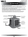
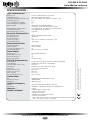
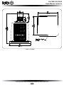
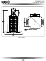
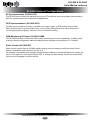
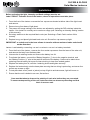
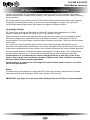
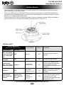
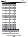
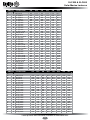
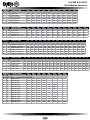
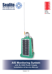
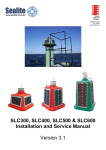
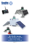
SLC500 & SLC600
Solar Marine Lanterns
Installation & Service Manual
Version 4.0
SLC500 & SLC600
Solar Marine Lanterns
Table of Contents
Introduction...........................................................................................Page 4
Operating Principle..............................................................................Page 4
Technology............................................................................................Page 4
SLC500 Model.......................................................................................Page 5
SLC500 Optional Configurations..................................................Page 8
SLC600 Model.......................................................................................Page 9
SLC500 Optional Configurations................................................Page 12
Installation...........................................................................................Page 13
RF Synchronisation (Comm-Sync) Option ......................................Page 15
GPS Synchronisation Option............................................................Page 16
Lantern Status....................................................................................Page 17
Flash Codes........................................................................................Page 19
Maintenance and Servicing...............................................................Page 24
Trouble Shooting................................................................................Page 25
Sealite Lantern Warranty...................................................................Page 27
Version No.
3.2
4.0
Description
Update Manual
Update Spec Table & Remove SLC400
Date
August 2010
May 2012
Approved
K. Paton
J. Dore
Latest products and information available at www.sealite.com
3
SLC500 & SLC600
Solar Marine Lanterns
Introduction
Congratulations! By choosing to purchase a Sealite lantern you have become the owner of
one of the most advanced LED marine lanterns in the world.
Sealite Pty Ltd has been manufacturing lanterns for over 25 years, and particular care has been taken to
ensure your lantern gives years of service.
As a commitment to producing the highest quality products for our customers, Sealite has been independently
certified as complying with the requirements of ISO9001:2008 quality management system.
Sealite lanterns comply with requirements of the US Coast Guard in 33 CFR part 66 for Private Aids To
Navigation.
By taking a few moments to browse through this booklet, you will become familiar with the versatility of your
lantern, and be able to maximise its operating function.
Please remember to complete the Sealite warranty registration card accompanying your lantern.
Operating Principle
The solar module of the lantern converts sunlight to an electrical current that is used to charge the battery. The
battery provides power to operate the lantern at night.
The flasher unit has very low current requirements. A microprocessor drives an array of ultra bright LED’s
through a DC/DC converter, which enables the LED’s to operate within the manufacturer’s specifications. The
battery is protected from over-charging within the circuit to ensure maximum battery life.
On darkness, the microprocessor will initiate a program check and after approximately 1 minute begin flashing
to the set code
Technology
Sealite is the world’s fastest growing manufacturer of marine aids to navigation. We
employ leading mechanical, optical, hardware & software engineers to create innovative
products to service the needs of our customers worldwide, and offer the widest range of
solar-powered LED lanterns in the marketplace.
Electronics
Sealite employs leading in-house electronic engineers in the design and development of software and related
circuitry. All individual electronic components are sourced directly by Sealite procurement staff ensuring that
only the highest quality components are used in our products.
LED Technology
All marine lanterns use the latest advancements in LED (Light Emitting Diode) technology as a light source.
The major advantage of LED’s over traditional light sources is well established in that they typically have an
operational life in excess of 100,000 hours, resulting in substantial savings to maintenance and servicing
costs.
Precision Construction
Commitment to investing in the design and construction of injection-moulded parts including optic lenses, light
bases and a range of other components ensures that all Sealite products are of a consistent & superior quality.
Optical Performance
Sealite manufactures a range of marine LED lenses moulded from multi-cavity dies. Complex shapes such as
the SL70, BargeSafe™ and 16-segment multi-focus lenses are a testament to the company’s superior
in-house lens manufacturing capabilities and outstanding optical performance.
Award-winning, Patented Technology
Several United States and Australian patent registrations are held on Sealite’s range of innovative designs,
with other regional patents pending in Canada, United Kingdom and Europe.
Latest products and information available at www.sealite.com
4
SLC500 & SLC600
Solar Marine Lanterns
SLC500 Model
The SLC500 is a completely self-contained 5-7nm+ Solar LED Marine Lantern designed for a
range of low-maintenance applications.
The light boasts a large internal battery compartment, a multiple tiered SL125 light-head, and 4
premium-grade 10watt solar modules mounted to collect sunlight at all angles.
The SLC500 is moulded from UV-stabilised virgin polyethylene, providing enormous impact
and weather resistance, in addition to high visibility colours.
The tough polycarbonate lens is specifically designed for use with LEDs, and incorporates an
environment-friendly spike - deterring unwelcome bird life. The lens design also ensures that
vessel operators clearly see the light from above, when passing the AtoN.
The user-friendly 2-piece design allows the lantern to be opened for convenient battery
inspection or replacement whilst the base remains fixed to the supporting structure.
SL125-2 light-head
(72 ultra-high intensity
LEDs. IP68 rating)
LED lens and Sealite’s
360o Omnidirectional
LED Reflector
(US Pat. No. 6,667,582.
AU Pat. No. 778,918)
High visibility
IALA colours for
daytime recognition
4 x 10watt
(40watts total)
multicrystalline solar
modules, ensuring
maximum light
collection to charge
the battery
Rotationally-moulded,
UV-stabilised, virgin
polyethylene body
Internal 55Ah battery
Latest products and information available at www.sealite.com
5
SLC500 & SLC600
Solar Marine Lanterns
SPECIFICATIONS •
Light Source
Available Colours
Maximum Available Intensity (cd)†
Visible Range (nm)
Horizontal Output (degrees)
Vertical Divergence (degrees)
Reflector Type
Available Flash Characteristics
Intensity Adjustments
LED Life Expectancy (hours)
SL125-2 (72 LED lantern as standard)
Red, Green, White, Yellow, Blue
Red - 383 Green - 317 White - 321 Yellow - 180
5–7+
360
9
Omnidirectional 360° LED Reflector
(US Pat. No. 6,667,582. AU Pat. No. 778,918)
Up to 256 IALA recommended (user adjustable)
Adjustable in 25% increments
>100,000
Current Draw (mA)
Circuit Protection
Nominal Voltage (v)
Autonomy (days)
Temperature Range
Refer to Sealite Power Calculator
Integrated
12
>30 (14 hour darkness, 12.5% duty cycle)
-40 to 80°C
Solar Module Type
Output (watts)
Solar Module Efficiency (%)
Charging Regulation
Multicrystalline
40 (4 x 10watt)
14
Microprocessor controlled
Battery Type
Battery Capacity (Ah)
Nominal Voltage (v)
Battery Service Life
SLA (Sealed Lead Acid)
55
12
Average 5 years
Body Material
Lens Material
Lens Diameter (mm/inches)
Lens Design
Mounting
Height (mm/inches)
Width (mm/inches)
Mass (kg/lbs)
Product Life Expectancy
Rotationally-moulded UV-stabilised virgin polyethylene
LEXAN® Polycarbonate – UV-stabilised
150 / 57/8
External optics with interior flute design
4 x 11mm mounting holes
806 / 313/4
560 / 22
35 / 771/8
Up to 12 years
CE
Quality Assurance
Waterproof
EN61000-6-3:1997. EN61000-6-1:1997
ISO9001:2008
IP68 light-head
Patents
Trademarks
US Pat. No. 6,667,582. AU Pat. No. 778,918
SEALITE® is a registered trademark of Sealite Pty Ltd
3 years
Electrical Characteristics
Solar Characteristics
Power Supply
Physical Characteristics
Certifications
Intellectual Property
Warranty *
Options Available
• 200mm OD mounting plate
• GPS Synchronisation
• RF Synchronisation
• GSM Monitoring & Control System
• Radio Control System
• Note - remote monitoring/control will reduce visible range of lantern
due to increased power consumption
Latest products and information available at www.sealite.com
6
• Specifications subject to change or variation without notice
* Subject to standard terms and conditions
† Intensity setting subject to solar availability
Light Characteristics
SLC500 & SLC600
Solar Marine Lanterns
Figure 1. SLC500
Latest products and information available at www.sealite.com
7
SLC500 & SLC600
Solar Marine Lanterns
SLC500 Optional Configurations
RF Synchronisation (SLC500-CS)
The SLC500 may be fitted with optional comm sync RF module for short range flash synchronisation ideal for marina entrances and aquaculture applications.
GPS Synchronisation (SLC500-GPS)
For flash synchronisation of lanterns installed over longer ranges, a GPS module may be fitted.
When lanterns flash in synchronisation they can be clearly distinguished from other navaids and
confusing background lighting - ideal for rivers and channel marking.
GSM Monitoring & Control (SLC500-GSM)
The SLC500 may also be fitted with GSM remote monitoring and control capabilities - enabling users
to access real-time diagnostics data and change lantern settings via cell-phone or PC interface.
Radio Control (SLC500-RC)
Radio control may be fitted to SLC500 model enabling users to remotely modify the setup of their
lantern via handheld radio controller (SL-RC-2.4).
For example, the operator can remotely change between different coloured LED banks (to change the
colour of the light), turn their lights ON and OFF, or change the flash setting. Perfect for remote traffic
control and to designate an area of activity.
Latest products and information available at www.sealite.com
8
SLC500 & SLC600
Solar Marine Lanterns
SLC600 Model
The SLC600 is the world’s largest self-contained LED lantern, is a 6-9nm+ Solar LED Marine
Lantern designed for a range of low-maintenance applications. The large solar array make this
lantern perfect for low sunlight regions.
The light boasts a large internal battery compartment, a multiple tiered SL125 light-head, and 4
premium-grade 20watt solar modules mounted to collect sunlight at all angles.
The SLC600 is moulded from UV-stabilised virgin polyethylene, providing enormous impact
and weather resistance, in addition to high visibility colours.
The tough polycarbonate lens is specifically designed for use with LEDs, and also enables
vessel operators clearly see the light from above, when passing the AtoN.
The user-friendly 2-piece design allows the lantern to be opened for convenient battery
inspection or replacement whilst the base remains fixed to the supporting structure.
LED lens and Sealite’s
360o Omnidirectional
LED Reflector
SL125-4 light-head
(144 ultra-high intensity
LEDs. IP68 rating)
(US Pat. No. 6,667,582.
AU Pat. No. 778,918)
4 x 20watt
(80watts total)
multicrystalline solar
modules, ensuring
maximum light
collection to charge
the battery
Rotationally-moulded,
UV-stabilised, virgin
polyethylene body
Internal 100Ah battery
High visibility
IALA colours for
daytime recognition
7-stage powder-coated
aluminium base with
handles for ease of
installation
Latest products and information available at www.sealite.com
9
SLC500 & SLC600
Solar Marine Lanterns
SPECIFICATIONS •
Light Source
Available Colours
Maximum Available Intensity (cd)†
Visible Range (nm)
Horizontal Output (degrees)
Vertical Divergence (degrees)
Reflector Type
Available Flash Characteristics
Intensity Adjustments
LED Life Expectancy (hours)
SL125-4 (144 LED lantern as standard)
Red, Green, White, Yellow, Blue
Red - 860 Green - 623 White - 602 Yellow - 363
6–9+
360
5
Omnidirectional 360° LED Reflector
(US Pat. No. 6,667,582. AU Pat. No. 778,918)
Up to 256 IALA recommended (user adjustable)
Adjustable in 25% increments
>100,000
Current Draw (mA)
Circuit Protection
Nominal Voltage (v)
Autonomy (days)
Temperature Range
Refer to Sealite Power Calculator
Integrated
12
>20 (14 hour darkness, 12.5% duty cycle)
-40 to 80°C
Solar Module Type
Output (watts)
Solar Module Efficiency (%)
Charging Regulation
Multicrystalline
80 (4 x 20watt)
14
Microprocessor controlled
Battery Type
Battery Capacity (Ah)
Nominal Voltage (v)
Battery Service Life
SLA (Sealed Lead Acid)
100
12
Average 5 years
Body Material
Lens Material
Lens Diameter (mm/inches)
Lens Design
Mounting
Height (mm/inches)
Width (mm/inches)
Mass (kg/lbs)
Product Life Expectancy
Rotationally-moulded UV-stabilised virgin polyethylene
LEXAN® Polycarbonate – UV-stabilised
150 / 57/8
External optics with interior flute design
4 x 11mm mounting holes
945/ 371/4
665 / 261/4
60 / 1321/4
Up to 12 years
CE
Quality Assurance
Waterproof
EN61000-6-3:1997. EN61000-6-1:1997
ISO9001:2008
IP68 light-head
Patents
Trademarks
US Pat. No. 6,667,582. AU Pat. No. 778,918
SEALITE® is a registered trademark of Sealite Pty Ltd
3 years
Electrical Characteristics
Solar Characteristics
Power Supply
Physical Characteristics
Certifications
Intellectual Property
Warranty *
Options Available
• 200mm OD mounting plate
• GPS Synchronisation
• RF Synchronisation
• AIS Remote Monitoring
• GSM Monitoring & Control System
• Radio Control System
• Note - remote monitoring/control will reduce visible range of lantern
due to increased power consumption
• 9 degree lens
Latest products and information available at www.sealite.com
10
• Specifications subject to change or variation without notice
* Subject to standard terms and conditions
† Intensity setting subject to solar availability
Light Characteristics
SLC500 & SLC600
Solar Marine Lanterns
Figure 2. SLC600
Latest products and information available at www.sealite.com
11
SLC500 & SLC600
Solar Marine Lanterns
SLC600 Optional Configurations
RF Synchronisation (SLC600-CS)
The SLC600 may be fitted with optional comm sync RF module for short range flash synchronisation ideal for marina entrances and aquaculture applications.
GPS Synchronisation (SLC600-GPS)
For flash synchronisation of lanterns installed over longer ranges, a GPS module may be fitted.
When lanterns flash in synchronisation they can be clearly distinguished from other navaids and
confusing background lighting - ideal for rivers and channel marking.
GSM Monitoring & Control (SLC600-GSM)
The SLC600 may also be fitted with GSM remote monitoring and control capabilities - enabling users
to access real-time diagnostics data and change lantern settings via cell-phone or PC interface.
Radio Control (SLC600-RC)
Radio control may be fitted to SLC600 model enabling users to remotely modify the setup of their
lantern via handheld radio controller (SL-RC-2.4).
For example, the operator can remotely change between different coloured LED banks (to change the
colour of the light), turn their lights ON and OFF, or change the flash setting. Perfect for remote traffic
control and to designate an area of activity.
Latest products and information available at www.sealite.com
12
SLC500 & SLC600
Solar Marine Lanterns
Installation
Before activating the light, intensity and flash settings must be set.
Label “FRONT” indicates front of the lantern, where all operations must take place.
1. From the front of the lantern unscrew the four cap screws located at either side of the light-head
and remove.
2. Remove bung from base of light-head.
3. The power and range settings of the lantern are adjusted by setting the DIP switches inside the
lantern. Your lantern is normally set to maximum range (see ‘Selecting an Intensity Setting’ section
of this manual).
4. Set rotary switches to the required flash code (see ‘Selecting a Flash Code’ section of this
manual). 5. Replace bung, and place light-head back onto unit. Screw four cap screws up tight.
IMPORTANT: a sealed vent in the base allows air transfer without moisture intake and should
not be disturbed.
Lantern is activated by connecting +ve and -ve wires to +ve and -ve battery terminals.
1. From the front of the lantern, unscrew the four socket cap screws from the base of the solar unit,
and remove the body from the base plate.
2. Unscrew the 4 retaining knobs and remove the battery box lid.
3. To activate the lantern, connect the “Battery Negative (-)” wire to the negative terminal, and
the “Battery Positive (+)” wire to the positive terminal of the battery. Care must be taken when
replacing internal battery lid to ensure internal wiring is clear from sealed gasket.
4. Replace the battery box lid, refit the 4 retaining knobs and tighten securely.
5. Replace the lantern body onto the base plate ensuring that no wiring is protruding, and screw four
socket cap screws up tight.
6. To test place dark cover (towel or jacket) on top of light to activate sensor, light will come on.
7. Ensure that the unit is bolted to an even, flat surface.
Care must be taken to observe the polarity of each wire before they are connected.
To ensure waterproofing of the unit, make sure that no wires are protruding and that
there is an even seal.
Latest products and information available at www.sealite.com
13
SLC500 & SLC600
Solar Marine Lanterns
Selecting an Intensity/Power Setting
Intensity/power settings on Sealite lanterns operate via DIP switches, located near the rotary switches
on the flasher unit. The pulse settings may be used to reduce the power consumption and intensity
of the lantern. Setting the lantern to 25% intensity will reduce the power consumption to 25% of the
normal 100% setting and the range by 25%. This setting may be used to adjust the current draw of the
light to local sunlight conditions.
The following diagrams indicate intensity/power settings:- ON
1
ON
2
1
100%
ON
2
1
75%
ON
2
1
50%
2
25%
Selecting a Flash Code- Rotary Switches A and B
All lanterns have 2 rotary switches marked A and B on the flasher unit. Turning the small arrows to the
appropriate number or letter will set the code. The unit may take up to one minute to activate a new
flash code. A comprehensive list of available flash codes is listed on in the ‘Flash Codes’ section of this
manual.
0.3
2.7
789A
23
FL 3 S
23
789A
BCD
456
B
E
OFF
F01
F01
0
ON
BCD
A
FLASH CODE
E
SWITCH
A
B
456
Example:
Latest products and information available at www.sealite.com
14
A
SLC500 & SLC600
Solar Marine Lanterns
RF Synchronisation (Comm-Sync) Option
Sealite’s innovative RF Synchronisation System is designed to offer a low-cost short range flash
synchronisation option for applications including rivers, estuaries, marina entrances, channel marking
and aquaculture.
RF Synchronisation may be fitted to the SLC500 and SLC600 lanterns and benefits vessel operators
at night by illuminating the boundary or channel as a clear passage on entrance, as opposed to
indiscriminant flashing lights which may render the judgment of distance difficult.
Operating Principle
RF Comm-Sync products are fitted with an internal RF module, which operates on a 2.4GHz
frequency and has an operational range of up to 1.4km between 2 lights.
Should more than 2 lanterns be required to be synchronised the range may be extended for longer
distances as each lantern transmits the data to all adjacent lanterns - causing them to fall into
synchronisation. The only limitation is that no lantern should be more than 1.4km from the next lantern
in the series.
RF Comm-Sync lanterns operate within a peer-to-peer network topology and therefore are not
dependent upon master/slave relationships. This means that lights remain synchronised without use of
master/slave configurations and each lantern in the network shares both the roles of master and slave.
Using innovative software, the additional power consumption is minimal, and in most configurations
the solar lantern requires only 1.5hrs of direct sunlight per day to retain full working autonomy.
Synchronisation is recommended for lanterns operating with up to 20% duty cycles and in
regions where typical solar irradiation averages 1.5Kwh per day. Flash characters exceeding
this may require lantern intensity adjustment.
Synchronisation is achieved via short-range RF communication between lanterns, and relies
on line-of-sight operation.
Setup
To enable flash synchronisation of independent RF Comm-Sync lanterns, set lanterns to the same
flash characteristic (see “Selecting a Flash Code” section of this manual).
IMPORTANT: only lights set to the exact same flash pattern/code will flash in synchronisation.
Latest products and information available at www.sealite.com
15
SLC500 & SLC600
Solar Marine Lanterns
GPS Synchronisation Option
The SLC500 and SLC600 lanterns may be fitted with an optional internally integrated GPS module
which enables flash synchronisation of lanterns installed over longer ranges.
When lanterns flash in synchronisation they can be clearly distinguished from other navaids and
confusing background lighting. Users are able to mark a channel, port or river with independently
operating lanterns that all flash in synchronisation which improves the effectiveness of marker lights by
highlighting the outline each time the lanterns turn on.
No additional power supplies, aerials or control systems are required, and with its microprocessorbased system, the GPS option is specifically designed to provide maximum reliability and performance
over a wide range of environmental conditions. The GPS board is a separate PCB mounted above the
standard lantern circuitry.
Operating Principle
Each light operates independently and requires no operator intervention. A minimum of 3 satellites
need to be in view for the built-in GPS receiver to collect time data. At dusk, the light sensor will turn
the light on. If time data is available the light will come on synchronised to every other light with the
same selected flash code.
Synchronisation is achieved using an internal algorithm based on the highly accurate time base and
time data received from the satellites. The satellite data is provided from a number of earth stations
using atomic clocks as the time base. Continuous self-checking ensures that the light will continue to
run in synchronisation.
Light Activation
At power-up the microprocessor checks that the internal GPS module is programmed correctly and is
able to provide valid time base and time data.
The light then checks for day/night. If it is daylight the internal microprocessor will go to idle mode after
approximately 10 seconds. This reduces the overall power consumption when the light is not required.
Once outside with a clear view of the sky, valid data should become available within 20 minutes.
Daylight Operation
During daylight hours the microprocessor is in idle mode to reduce power consumption. Time data
continues to be updated once per second. The microprocessor will automatically exit the idle mode as
soon as dark conditions are detected.
Dark Operation
When dark conditions are detected the light:
•
Checks for valid time data and is turned on after a delay based on the current time and the length
of the selected flash code;
•
If valid time data is not detected the light will turn on after approximately 10 seconds. This light will
not be synchronised.
•
If the light turns on unsynchronised it will continually check for valid time data. Once valid data is
found the light will automatically synchronise.
Setup
To enable flash synchronisation of independent RF Comm-Sync lanterns, set lanterns to the same
flash characteristic (see “Selecting a Flash Code” section of this manual).
IMPORTANT: only lights set to the exact same flash pattern/code will flash in synchronisation.
Latest products and information available at www.sealite.com
16
SLC500 & SLC600
Solar Marine Lanterns
Lantern Status
Two status LED’s on the main printed circuit board (position A in image below) provide the operator
with an indication of the lantern status.
There is one RED and one YELLOW LED that in different combinations of ON/OFF/FLASHING will
indicate the current operational status of the light,and vary depending on whether the lantern is set to
steady-on, or a flashing light characteristic.
These indicator LED’s can be viewed at the base of the lens. Separate indicator LEDs are located on
the top of the GPS circuit board (where fitted- see position B & C of figure 3.1.).
Figure 3.1.
STEADY LIGHT
LED Combinations
(Status Indicator LEDs ‘A’ in Fig.3.1.)
Lantern Status
Lantern
Comment
YELLOW LED
RED LED
Flashing ON/
OFF very quick 9
times per second
then 11 seconds
off
OFF
Normal
OFF
Normal running condition in
daylight.
Flashing
constant
OFF
Normal
ON
Normal running condition.
Flashing ON/
OFF very quick 9
times per second
Fixed-on
Low Battery
Voltage (<8v)
OFF
Battery is flat. Battery must
receive charge and light must
see daylight for at least 1
minute before resuming normal
operation.
Fixed-on
OFF
High Solar
Voltage (>15.3v)
ON
Battery is in state of very high
charge. Check regulator if
persists.
Flashing ON/
OFF 9 times per
second
Flashing ON/
OFF 1 time per
second
High internal
ambient
temperature
(>75°C)
ON
Internal ambient temperature is
>75°C. Selected light intensity
is dropped by 25%. Will
resume normal operation when
temperature <75°C.
Latest products and information available at www.sealite.com
17
SLC500 & SLC600
Solar Marine Lanterns
FLASHING LIGHT
LED Combinations
(Status Indicator LEDs ‘A’ in Fig.3.1.)
YELLOW LED
A. Flashing ON/
OFF 1 time per
second
RED LED
Lantern Status
Lantern
Comment
ON
Normal running condition
synchronised to GPS. Will take
up to 10 minutes when first
powered up. Condition only
active in darkness..
OFF
Normal but not
synchronised
ON
Normal running condition, but
light does not synchronise to
other lights. GPS not fitted or no
time data received.
OFF
Normal
OFF
Normal running condition in
daylight.
OFF
Normal and
synchronised
when GPS fitted
B. Flashing ON/
OFF very
quick constant
C. Flashing ON/
OFF very
quick 9 times
second then
11 seconds off
Flashing ON/
OFF very quick 9
times per second
Fixed-on
Low Battery
Voltage (<8v)
OFF
Battery is flat. Battery must
receiver charge and light must
see daylight for at least 1
minute before resuming normal
operation.
Fixed-on
OFF
High Solar
Voltage (>15.3v)
ON
Battery is in state of very high
charge. Check regulator if
persists.
Flashing ON/
OFF 1 time per
second
Flashing ON/
OFF 1 time per
second
High internal
ambient
temperature
(>75°C)
ON
Internal ambient temperature is
>75°C. Selected light intensity
is dropped by 25%. Will
resume normal operation when
temperature <75°C.
NOTE
1. 1 second interval flashing Yellow LED indicates light is operating in synchronisation with the
optional fitted GPS correctly.
2. If checking in daylight lantern must be covered to activate flash pattern.
GPS BOARD (where fitted)
LED Combinations
YELLOW LED
Lantern Status
RED LED
Lantern
Comment
(GPS Status Indicator LEDs ‘B’ in Fig.3.1.)
A. ON steady
OFF
B. Flashing ON/
OFF very
quick constant
Flashing ON/
OFF very quick
constant faint
Normal
C. Flashes in
sequence with
red LED
Flashes in
sequence with
yellow LED
Off
ON or
OFF
Normal
GPS powered up.
(GPS Status Indicator LEDs ‘C’ in Fig.3.1.)
ON
OFF/ON
GPS software running.
GPS software not operational.
Latest products and information available at www.sealite.com
18
SLC500 & SLC600
Solar Marine Lanterns
Flash Codes
Sealite Lanterns may be set to any of 256 IALA recommended flash settings which are user-adjustable
onsite without the need for external devices.
SEALITE® code reference is listed by number of flashes
For the latest version of this document visit www.sealite.com
or email [email protected]
Symbols
FL
Flash followed by number Eg. FL 1 S, one flash every second
FFixed
Q
Quick flash
VQ
Very quick flash
OC
Occulting; greater period on than off
ISO
Isophase; equal period on and off
LFL Long flash long
MO
Morse code ( ) contains letter
For example, VQ (6) + LFL 10 S means 6 very quick flashes followed by a long flash, during a
10-second interval.
The amount of power your lantern draws through the night depends on the duty cycle, i.e. the amount of
time on as a proportion to the timing cycle. For example, 0.5 seconds on and 4.5 seconds off equals a
10% duty cycle.
It is best to operate at the lowest duty cycle appropriate to the actual needs of the application.
Recommended Rhythm for Flashing Light - IALA Regions A and B
MARK DESCRIPTION
RHYTHM
Port Hand & Starboard Marks:
Any, other than Composite Group Flashing (2+1)
Preferred Channel Starboard:
Composite Group Flashing (2+1)
Preferred Channel Port:
Composite Group Flashing (2+1)
North Cardinal Mark:
Very quick or quick
East Cardinal Mark:
Very quick (3) every 5 seconds or quick (3) every 10 seconds
South Cardinal Mark:
Very quick (6) + long flash every 10 seconds or quick (6) + long flash every 15 seconds
West Cardinal Mark:
Very quick (9) every 10 seconds or quick (9) every 15 seconds
Isolated Danger Mark:
Group flashing (2)
Safe Water Mark:
Isophase, occulting, one long flash every 10 seconds or Morse Code “A”
Special Marks:
Any, other than those described for Cardinal, Isolated Danger or Safe Water Marks
Latest products and information available at www.sealite.com
19
SWITCH
A
B
0
D
E
F
7
8
9
A
8
B
9
C
F
1
0
0
2
3
4
5
6
7
1
8
9
D
1
A
2
B
3
C
D
2
5
E
4
4
5
E
F
6
0
1
2
3
3
F
3
8
4
5
9
6
0
3
3
3
3
3
3
3
4
3
4
3
4
0
5
4
0
0
0
0
0
0
2
0
0
6
5
0
5
0
5
0
0
2
4
2
6
5
5
0
0
5
1
1
1
2
6
2
1
5
1
1
5
1
FLASH CODE
ON
OFF
F (Steady light)
VQ 0.5 S
VQ 0.6 S
VQ 0.6 S
Q1S
Q1S
Q1S
Q1S
Q1S
Q 1.2 S
Q 1.2 S
Q 1.2 S
FL 1.5 S
FL 1.5 S
FL 1.5 S
FL 1.5 S
FL 2 S
FL 2 S
FL 2 S
FL 2 S
FL 2 S
FL 2 S
ISO 2 S
FL 2.5 S
FL 2.5 S
FL 2.5 S
FL 3 S
FL 3 S
FL 3 S
FL 3 S
FL 3 S
FL 3 S
FL 3 S
ISO 3 S
OC 3 S
OC 3 S
OC 3.5 S
FL 4 S
FL 4 S
FL 4 S
FL 4 S
FL 4 S
FL 4 S
FL 4 S
FL 4 S
ISO 4 S
OC 4 S
OC 4 S
FL 4.3 S
FL 5 S
FL 5 S
FL 5 S
FL 5 S
FL 5 S
0.2
0.2
0.3
0.2
0.3
0.4
0.5
0.8
0.3
0.5
0.6
0.2
0.3
0.4
0.5
0.2
0.3
0.4
0.5
0.7
0.8
1.0
0.3
0.5
1.0
0.2
0.3
0.4
0.5
0.6
0.7
1.0
1.5
2.0
2.5
2.5
0.2
0.3
0.4
0.5
0.6
0.8
1.0
1.5
2.0
2.5
3.0
1.3
0.2
0.3
0.5
0.9
1.0
0.3
0.4
0.3
0.8
0.7
0.6
0.5
0.2
0.9
0.7
0.6
1.3
1.2
1.1
1.0
1.8
1.7
1.6
1.5
1.3
1.2
1.0
2.2
2.0
1.5
2.8
2.7
2.6
2.5
2.4
2.3
2.0
1.5
1.0
0.5
1.0
3.8
3.7
3.6
3.5
3.4
3.2
3.0
2.5
2.0
1.5
1.0
3.0
4.8
4.7
4.5
4.1
4.0
SWITCH
A
B
7
4
8
0
1
2
C
B
C
8
9
A
7
B
5
9
6
3
4
A
9
5
D
C
E
B
6
A
6
B
F
C
7
0
1
D
2
E
1
C
D
7
2
8
5
6
F
D
3
0
4
7
A
E
1
2
2
3
3
3
6
5
5
1
1
1
5
1
2
2
4
3
3
4
6
6
5
1
5
4
2
2
6
2
5
4
6
6
6
1
6
1
4
2
2
2
4
6
3
3
1
4
4
2
4
4
6
4
FLASH CODE
ON
OFF
FL 5 S
ISO 5 S
LFL 5 S
OC 5 S
OC 5 S
OC 5 S
FL 6 S
FL 6 S
FL 6 S
FL 6 S
FL 6 S
FL 6 S
FL 6 S
FL 6 S
ISO 6 S
LFL 6 S
OC 6 S
OC 6 S
OC 6 S
FL 7 S
FL 7 S
OC 7 S
FL 7.5 S
FL 7.5 S
FL 8 S
FL 8 S
ISO 8 S
LFL 8 S
OC 8 S
LFL 8 S
FL 9 S
FL 9 S
OC 9 S
FL 10 S
FL 10 S
FL 10 S
FL 10 S
FL 10 S
FL 10 S
LFL 10 S
LFL 10 S
ISO 10 S
LFL 10 S
OC 10 S
OC 10 S
OC 10 S
FL 12 S
FL 12 S
LFL 12 S
FL 15 S
LFL 15 S
OC 15 S
LFL 20 S
FL 26 S
1.5
2.5
2.0
3.0
4.0
4.5
0.2
0.3
0.4
0.5
0.6
1.0
1.2
1.5
3.0
2.0
4.0
4.5
5.0
1.0
2.0
4.5
0.5
0.8
0.5
1.0
4.0
2.0
5.0
3.0
0.9
1.0
6.0
0.2
0.3
0.5
0.8
1.0
1.5
2.0
3.0
5.0
4.0
6.0
7.0
7.5
1.2
2.5
2.0
1.0
4.0
10
2.0
1.0
3.5
2.5
3.0
2.0
1.0
0.5
5.8
5.7
5.6
5.5
5.4
5.0
4.8
4.5
3.0
4.0
2.0
1.5
1.0
6.0
5.0
2.5
7.0
6.7
7.5
7.0
4.0
6.0
3.0
5.0
8.1
8.0
3.0
9.8
9.7
9.5
9.2
9.0
8.5
8.0
7.0
5.0
6.0
4.0
3.0
2.5
10.8
9.5
10.0
14.0
11.0
5.0
18.0
25.0
Latest products and information available at www.sealite.com.au
20
SLC500 & SLC600
Solar Marine Lanterns
SWITCH
A
B
0
A
E
B
1
A
2
A
3
A
F
9
2
C
4
A
0
7
1
7
9
B
2
9
5
A
7
8
A
A
6
A
7
A
9
9
2
8
3
7
3
9
A
9
7
B
8
A
4
7
8
8
5
7
4
C
5
C
F
B
9
A
9
8
6
7
7
7
6
9
8
7
B
9
9
7
4
9
B
A
C
9
D
9
A
8
A
7
8
B
C
A
D
A
FLASH CODE
ON
OFF
ON
OFF
FL (2) 4 S
VQ (2) 4 S
FL (2) 4.5 S
FL (2) 4.5 S
FL (2) 4.5 S
FL (2) 5 S
FL (2) 5 S
FL (2) 5 S
FL (2) 5 S
FL (2) 5 S
Q (2) 5 S
Q (2) 5 S
FL (2) 5.5 S
FL (2) 6 S
FL (2) 6 S
FL (2) 6 S
FL (2) 6 S
FL (2) 6 S
FL (2) 6 S
FL (2) 6 S
Q (2) 6 S
FL (2) 7 S
FL (2) 8 S
FL (2) 8 S
FL (2) 8 S
FL (2) 8 S
FL (2) 8 S
OC (2) 8 S
OC (2) 8 S
VQ (2) 8 S
FL (2) 10 S
FL (2) 10 S
FL (2) 10 S
FL (2) 10 S
FL (2) 10 S
FL (2) 10 S
FL (2) 10 S
FL (2) 10 S
Q (2) 10 S
FL (2) 12 S
FL (2) 12 S
FL (2) 12 S
FL (2) 15 S
FL (2) 15 S
Q (2) 15 S
FL (2) 20 S
FL (2) 25 S
0.5
0.2
0.3
0.4
0.5
0.2
0.2
0.4
0.5
1.0
0.3
0.5
0.4
0.3
0.3
0.3
0.4
0.5
0.8
1.0
0.3
1.0
0.4
0.4
0.5
0.8
1.0
3.0
5.0
0.2
0.4
0.5
0.5
0.5
0.5
0.8
1.0
1.0
0.6
0.4
0.5
1.5
0.5
1.0
0.2
1.0
1.0
1.0
1.0
1.0
1.0
1.0
0.8
1.2
0.6
1.0
1.0
0.7
0.5
1.4
0.6
0.9
1.0
1.0
1.0
1.2
1.0
0.7
1.0
0.6
1.0
1.0
1.2
1.0
2.0
1.0
1.0
1.6
0.5
1.0
1.5
2.0
1.2
1.0
1.5
0.4
1.0
1.0
2.0
1.5
2.0
0.8
3.0
1.0
0.5
0.2
0.3
0.4
0.5
0.2
0.2
0.4
0.5
1.0
0.3
0.5
0.4
1.0
0.3
0.3
0.4
0.5
0.8
1.0
0.3
1.0
2.0
0.4
0.5
2.4
1.0
1.0
1.0
0.2
0.4
1.5
0.5
0.5
0.5
0.8
1.0
1.0
0.6
0.4
0.5
1.5
2.0
1.0
0.2
1.0
1.0
2.0
2.6
2.9
2.7
2.5
3.8
3.4
3.6
3.0
2.0
3.7
3.5
3.3
4.1
4.5
4.4
4.2
4.0
3.2
3.0
4.7
4.0
5.0
6.2
6.0
3.6
5.0
2.0
1.0
6.6
7.6
7.5
8.0
7.5
7.0
7.2
7.0
6.5
8.4
10.2
10.0
7.0
11.0
11.0
13.8
15.0
22.0
SWITCH
A
B
7
9
5
9
0
C
E
9
3
C
2
B
FLASH CODE
ON
OFF
ON
OFF
ON
OFF
Q (3) 5 S
VQ (3) 5 S
VQ (3) 5 S
VQ (3) 5 S
FL (3) 6 S
FL (2+1) 6 S
0.5
0.2
0.3
0.3
0.5
0.3
0.5
0.3
0.2
0.3
1.0
0.4
0.5
0.2
0.3
0.3
0.5
0.3
0.5
0.3
0.2
0.3
1.0
1.2
0.5
0.2
0.3
0.3
0.5
0.3
2.5
3.8
3.7
3.5
2.5
3.5
Latest products and information available at www.sealite.com
21
SLC500 & SLC600
Solar Marine Lanterns
SWITCH
A
B
A
B
F
A
0
B
B
7
B
8
C
8
C
B
C
7
D
B
D
7
3
8
8
9
B
B
D
8
1
B
E
A
E
7
B
6
4
8
5
8
1
8
F
7
9
D
0
8
F
8
0
9
1
9
6
8
1
C
4
B
3
B
5
B
6
B
SWITCH
A
B
B
F
B
D
8
D
1
D
2
D
F
E
B
E
4
F
C
E
3
D
A
D
4
D
8
E
7
D
D
E
C
D
5
D
0
D
3
F
0
F
E
E
6
F
FLASH CODE
ON
OFF
ON
OFF
ON
OFF
Q (3) 6 S
FL (3) 8 S
FL (3) 9 S
FL (3) 9 S
FL (3) 10 S
FL (3) 10 S
FL (3) 10 S
FL (3) 10 S
FL (3) 10 S
FL (3) 10 S
FL (2+1) 10 S
OC (3) 10 S
Q (3) 10 S
FL (2 + 1) 10 S
FL (3) 12 S
FL (3) 12 S
FL (3) 12 S
FL (3) 12 S
FL (2+1) 12 S
FL (2+1) 12 S FL (2+1) 13.5 S
FL (3) 15 S
FL (3) 15 S
FL (3) 15 S
FL (2+1) 15 S
FL (2+1) 15 S
FL (2+1) 15 S
FL (2+1) 15 S
VQ (3) 15 S
FL (3) 20 S
FL (3) 20 S
FL (3) 20 S
FL (3) 20 S
0.3
0.5
0.3
0.8
0.3
0.4
0.5
0.5
0.6
1.0
0.5
5.0
0.3
0.5
0.5
0.5
0.8
1.0
0.8
1.0
1.0
0.3
0.4
0.5
0.6
0.7
0.7
1.0
0.1
0.5
0.5
0.8
1.0
0.7
1.0
1.0
1.2
0.7
0.6
0.5
1.5
0.6
1.0
0.7
1.0
0.7
0.5
1.5
2.0
1.2
1.0
1.2
1.0
1.0
1.7
1.0
1.5
0.3
0.5
0.7
2.0
0.5
3.0
1.5
1.2
1.0
0.3
0.5
0.3
0.8
0.3
0.4
0.5
0.5
0.6
1.0
0.5
1.0
0.3
0.5
0.5
0.5
0.8
1.0
0.8
1.0
1.0
0.3
0.4
0.5
0.6
0.7
0.7
1.0
0.1
0.5
0.5
0.8
1.0
0.7
1.0
1.0
1.2
0.7
0.6
0.5
1.5
0.6
1.0
2.1
1.0
0.7
0.5
1.5
2.0
1.2
3.0
2.4
4.0
4.0
1.7
1.0
1.5
0.3
0.5
0.7
5.0
0.5
3.0
1.5
1.2
1.0
0.3
0.5
0.3
0.8
0.9
1.2
0.5
0.5
0.6
1.0
0.5
1.0
0.3
1.5
0.5
0.5
0.8
1.0
0.8
1.0
1.0
0.3
0.4
0.5
1.4
1.9
2.1
1.0
0.1
0.5
0.5
0.8
1.0
3.7
4.5
6.1
4.2
7.1
6.8
7.5
5.5
7.0
5.0
5.7
1.0
7.7
6.5
7.5
6.5
7.2
5.0
6.0
4.0
5.5
10.7
11.8
10.5
11.8
10.7
10.1
5.0
13.7
12.5
15.5
15.2
15.0
FLASH CODE
ON
OFF
ON
OFF
ON
OFF
ON
OFF
VQ (4) 4 S
Q (4) 6 S
Q (4) 6 S
FL (4) 10 S
FL (4) 10 S
Q (4) 10 S
FL (4) 12 S
FL (4) 12 S
FL (4) 12 S
FL (4) 12 S
Q (4) 12 S
FL (4) 15 S
FL (4) 15 S
FL (4) 15 S
FL (4) 16 S
FL (4) 20 S
FL (4) 20 S
FL (4) 20 S
FL (4) 20 S
Q (4) 20 S
Q (4) 28 S
FL (4) 30 S
0.3
0.3
0.4
0.5
0.8
0.3
0.3
0.5
0.5
0.8
0.3
0.5
1.0
1.5
0.5
0.3
0.5
0.5
1.5
0.5
0.5
0.5
0.3
0.7
0.6
1.0
1.2
0.7
1.7
0.5
1.5
1.2
0.7
1.5
1.0
0.5
1.5
3.0
1.5
1.5
1.5
0.5
0.5
0.5
0.3
0.3
0.4
0.5
0.8
0.3
0.3
0.5
0.5
0.8
0.3
0.5
1.0
0.5
0.5
0.3
0.5
0.5
1.5
0.5
0.5
0.5
0.3
0.7
0.6
1.0
1.2
0.7
1.7
0.5
1.5
1.2
0.7
1.5
1.0
0.5
1.5
3.0
1.5
1.5
1.5
0.5
0.5
0.5
0.3
0.3
0.4
0.5
0.8
0.3
0.3
0.5
0.5
0.8
0.3
0.5
1.0
0.5
0.5
0.3
0.5
0.5
1.5
0.5
0.5
0.5
0.3
0.7
0.6
1.0
1.2
0.7
1.7
0.5
1.5
1.2
0.7
1.5
1.0
0.5
1.5
3.0
1.5
4.5
1.5
0.5
0.5
0.5
0.3
0.3
0.4
0.5
0.8
0.3
0.3
0.5
0.5
0.8
0.3
0.5
1.0
0.5
0.5
0.3
0.5
0.5
1.5
0.5
0.5
0.5
2.3
2.7
2.6
5.0
3.2
6.7
5.7
8.5
5.5
5.2
8.7
8.5
8.0
10.5
9.5
9.8
13.5
10.5
9.5
16.5
24.5
26.5
Latest products and information available at www.sealite.com
22
SLC500 & SLC600
Solar Marine Lanterns
SWITCH
A
B
D
D
E
D
E
8
5
F
9
F
9
E
SWITCH
A
B
F
D
A
F
7
F
A
E
SWITCH
A
B
6
E
7
E
2
F
2
E
3
E
8
F
SWITCH
A
B
4
E
5
E
1
F
0
E
1
E
FLASH CODE
ON
OFF
ON
OFF
ON
OFF
ON
OFF
ON
OFF
Q (5) 7 S
Q (5) 10 S
FL (5) 16.5 S
FL (5) 20 S
FL (5) 20 S
FL (5) 20 S
0.3
0.3
5.0
0.5
0.8
1.0
0.7
0.7
1.5
0.5
1.2
1.0
0.3
0.3
0.5
0.5
0.8
1.0
0.7
0.7
1.5
0.5
1.2
1.0
0.3
0.3
0.5
0.5
0.8
1.0
0.7
0.7
1.5
0.5
1.2
1.0
0.3
0.3
0.5
0.5
0.8
1.0
0.7
0.7
1.5
0.5
1.2
1.0
0.3
0.3
0.5
0.5
0.8
1.0
2.7
5.7
3.5
15.5
11.2
11.0
FLASH CODE
ON
OFF
ON
OFF
ON
OFF
ON
OFF
ON
OFF
ON
OFF
Q (6) 10 S
FL (6) 15 S
FL (6) 15 S
FL (6) + LFL 15 S
0.3
0.3
0.5
0.5
0.7
0.7
1.0
1.0
0.3
0.3
0.5
0.5
0.7
0.7
1.0
1.0
0.3
0.3
0.5
0.5
0.7
0.7
1.0
1.0
0.3
0.3
0.5
0.5
0.7
0.7
1.0
1.0
0.3
0.3
0.5
0.5
0.7
0.7
1.0
1.0
0.3
0.3
0.5
0.5
4.7
9.7
7.0
7.0
FLASH CODE
ON
OFF
ON
OFF
ON
OFF
ON
OFF
ON
OFF
ON
OFF
ON
OFF
VQ (6) + LFL 10 S
VQ (6) + LFL 10 S
Q (6) + LFL 15 S
Q (6) + LFL 15 S
Q (6) + LFL 15 S
VQ (6) + LFL 15 S
0.2
0.3
0.2
0.3
0.6
0.3
0.3
0.3
0.8
0.7
0.6
0.3
0.2
0.3
0.2
0.3
0.6
0.3
0.3
0.3
0.8
0.7
0.6
0.3
0.2
0.3
0.2
0.3
0.6
0.3
0.3
0.3
0.8
0.7
0.6
0.3
0.2
0.3
0.2
0.3
0.6
0.3
0.3
0.3
0.8
0.7
0.6
0.3
0.2
0.3
0.2
0.3
0.6
0.3
0.3
0.3
0.8
0.7
0.6
0.3
0.2
0.3
0.2
0.3
0.6
0.3
0.3
0.3
0.8
0.7
0.6
0.3
2.0
2.0
2.0
2.0
2.0
2.0
5.0
4.4
7.0
7.0
5.8
9.4
FLASH CODE
ON
OFF
ON
OFF
ON
OFF
ON
OFF
ON
OFF
ON
OFF
ON
OFF
ON
OFF
ON
OFF
VQ (9) 10 S
VQ (9) 10 S
Q (9) 15 S
Q (9) 15 S
Q (9) 15 S
0.2
0.3
0.2
0.3
0.6
0.3
0.3
0.8
0.7
0.6
0.2
0.3
0.2
0.3
0.6
0.3
0.3
0.8
0.7
0.6
0.2
0.3
0.2
0.3
0.6
0.3
0.3
0.8
0.7
0.6
0.2
0.3
0.2
0.3
0.6
0.3
0.3
0.8
0.7
0.6
0.2
0.3
0.2
0.3
0.6
0.3
0.3
0.8
0.7
0.6
0.2
0.3
0.2
0.3
0.6
0.3
0.3
0.8
0.7
0.6
0.2
0.3
0.2
0.3
0.6
0.3
0.3
0.8
0.7
0.6
0.2
0.3
0.2
0.3
0.6
0.3
0.3
0.8
0.7
0.6
0.2
0.3
0.2
0.3
0.6
5.8
4.9
6.8
6.7
4.8
SWITCH FLASH CODE
ON OFF
A
B
MORSE CODE ( ) INDICATES LETTER
7
8
MO (A) 6 S
0.3
0.6
7
B
MO (A) 8 S
0.4
0.6
8
8
MO (A) 8 S
0.8
1.2
B
8
MO (U) 10 S
0.3
0.7
C
8
MO (U) 10 S
0.4
0.6
D
8
MO (U) 10 S
0.5
0.5
9
8
MO (A) 10 S
0.5
0.5
8
9
MO (D) 10 S
5.0
1.0
A
8
MO (A) 15 S
0.5
1.5
F
8
MO (U) 15 S
0.6
0.3
0
9
MO (U) 15 S
0.7
0.5
1
9
MO (U) 15 S
0.7
0.7
7
D
MO (B) 15 S
1.5
0.5
ON
OFF
1.0
2.0
2.4
0.3
0.4
0.5
1.5
1.0
2.0
0.6
0.7
0.7
0.5
4.1
5.0
3.6
0.7
0.6
0.5
7.5
1.0
11.0
0.3
0.5
0.7
0.5
ON
OFF
0.9
1.2
1.5
7.1
6.8
6.5
1.0
1.0
1.4
1.9
2.1
0.5
11.8
10.7
10.1
0.5
ON
OFF
0.5
10.5
Latest products and information available at www.sealite.com
23
SLC500 & SLC600
Solar Marine Lanterns
Maintenance and Servicing
Designed to be virtually maintenance-free, the SLC500 and SLC600 require minimal attention, though
the following maintenance and servicing information is provided to help ensure the life of your Sealite
product.
1. Cleaning Lens- occasional cleaning of the light lens may be required. Using a cloth and warm
soapy water, wipe off any foreign matter before rinsing the lens with fresh water.
2. Cleaning Solar Panels- occasional cleaning of the solar panels may be required. Using a cloth and
warm soapy water, wipe off any foreign matter before rinsing the panels with fresh water.
3. Battery Check- inspection of batteries should be performed every three years (minimum) to ensure
that the charger, battery and ancillary electronics are functioning correctly. Using a voltage meter,
check that the battery voltage is at least 12 volts under 100MA load, and ensure all terminals are
clear of foreign matter (SL125-C models only).
Replacing the Battery
The SLC500 & SLC600 lanterns have a sealed battery compartment which provides the user
with the ability to change the battery after years of operation. The 2-piece design ensures ease of
maintenance, as the base remains fixed to the supporting structure.
1. From the front of the lantern, unscrew the four socket cap screws from the base of the lantern, and
remove the body from the base plate.
2. Unscrew the 4 retaining knobs and remove the battery box lid.
3. Disconnect the positive and negative wires from the battery.
4. Discard old battery in a safe manner.
5. Reattach positive and negative wires to the new battery.
6. Replace the battery box lid, refit the 4 retaining knobs and tighten securely.
7. Replace the lantern body onto the base plate ensuring that no wiring is protruding, and screw four
socket cap screws firmly.
8. To test place dark cover on top of light to activate sensor, light will come on.
Care must be taken to observe the polarity of each wire before they are connected.
To ensure waterproofing of the unit, make sure that no wires are protruding and that there is an
even seal.
Always discard old batteries in a safe manner.
Latest products and information available at www.sealite.com
24
SLC500 & SLC600
Solar Marine Lanterns
Trouble Shooting
Problem
Remedy
Lantern will not activate.
•
•
•
•
•
Timing codes will not change.
• Turn rotary switches several times to ensure contacts are clear.
Lantern will not operate for the
entire night.
• Expose lantern to direct sunlight and monitor operation for several days.
Sealite products typically require 3.0 hours of direct sunlight per day to
retain full autonomy. From a discharged state, the lantern may require
several days of operational conditions to ‘cycle’ up to full autonomy.
• Reducing the light output intensity or duty cycle (flash code) will reduce
current draw on the battery.
• Ensure solar module is clean and not covered by shading during the day.
Ensure lantern is in darkness.
Wait at least 60 seconds for the program to initialise in darkness.
Ensure switch setting is on a valid code (not unused flash code).
Ensure battery terminals are properly connected.
Ensure battery voltage is above 12volts.
Latest products and information available at www.sealite.com
25
SLC500 & SLC600
Solar Marine Lanterns
Sealite LED Light Warranty V2.1
Activating the Warranty
Upon purchase, the Sealite Pty Ltd warranty must be activated for recognition of future claims. To do
this you have two (2) options:
1. Postal Registration - please complete the Sealite Warranty Registration Card and return to
Sealite within 30 days of your purchase.
2. Online Registration - please complete the Online Registration Form at; www.sealite.com
Sealite Pty Ltd will repair or replace your LED light in the event of electronic failure for a period
of up to three years from the date of purchase.
The unit must be returned to Sealite freight prepaid.
Warranty Terms
1. Sealite Pty Ltd warrants that any Sealite marine products fitted with telemetry equipment including
but not limited to AIS, GSM, GPS or RF (“Telemetry Products”) will be free from defective materials
and workmanship under normal and intended use, subject to the conditions hereinafter set forth,
for a period of twelve (12) months from the date of purchase by the original purchaser.
2. Sealite Pty Ltd warrants that any BargeSafe™ Series of LED barge light products (“BargeSafe™
Products”) will be free from defective materials and workmanship under normal and intended use,
subject to the conditions hereinafter set forth, for a period of twelve (12) months from the date of
purchase by the original purchaser.
3. Sealite Pty Ltd warrants that any LED area lighting products (“Area Lighting Products”) but not
including sign lighting products will be free from defective materials and workmanship under
normal and intended use, subject to the conditions hereinafter set forth, for a period of twelve (12)
months from the date of purchase by the original purchaser.
4. Sealite Pty Ltd warrants that any LED sign lighting products (“Sign Lighting Products”) will be
free from defective materials and workmanship under normal and intended use, subject to the
conditions hereinafter set forth, for a period of three (3) years from the date of purchase by the
original purchaser.
5. Sealite Pty Ltd warrants that any Sealite marine lighting products other than the Telemetry
Products, BargeSafe™ Products, and Area Lighting Products (“Sealite Products”) will be free from
defective materials and workmanship under normal and intended use, subject to the conditions
hereinafter set forth, for a period of three (3) years from the date of purchase by the original
purchaser.
6. Sealite Pty Ltd will repair or replace, at Sealite’s sole discretion, any Telemetry Products,
BargeSafe™ Products, Area Lighting Products or Sealite Products found to be defective in
material and workmanship in the relevant warranty period so long as the Warranty Conditions (set
out below) are satisfied.
7. If any Telemetry Products, BargeSafe™ Products, Area Lighting Products or Sealite Products are
fitted with a rechargeable battery, Sealite Pty Ltd warrants the battery will be free from defect for a
period of one (1) year when used within original manufacturer’s specifications and instructions.
Warranty Conditions
This Warranty is subject to the following conditions and limitations;
1. The warranty is applicable to lanterns manufactured from 1/1/2009.
2. The warranty is void and inapplicable if:
a. the product has been used or handled other than in accordance with the instructions in the
owner’s manual and any other information or instructions provided to the customer by Sealite;
b. the product has been deliberately abused, or misused, damaged by accident or neglect or in
being transported; or
c. the defect is due to the product being repaired or tampered with by anyone other than Sealite
or authorised Sealite repair personnel.
Latest products and information available at www.sealite.com
26
SLC500 & SLC600
Solar Marine Lanterns
3. The customer must give Sealite Pty Ltd notice of any defect with the product within 30 days of the
customer becoming aware of the defect.
4. Rechargeable batteries have a limited number of charge cycles and may eventually need
to be replaced. Typical battery replacement period is 3-4 years. Long term exposure to high
temperatures will shorten the battery life. Batteries used or stored in a manner inconsistent with the
manufacturer’s specifications and instructions shall not be covered by this warranty.
5. No modifications to the original specifications determined by Sealite shall be made without written
approval of Sealite Pty Ltd.
6. Sealite lights can be fitted with 3rd party power supplies and accessories but are covered by the
3rd party warranty terms and conditions.
7. The product must be packed and returned to Sealite Pty Ltd by the customer at his or her
sole expense. Sealite Pty Ltd will pay return freight of its choice. A returned product must be
accompanied by a written description of the defect and a photocopy of the original purchase
receipt. This receipt must clearly list model and serial number, the date of purchase, the name and
address of the purchaser and authorised dealer and the price paid by the purchaser. On receipt
of the product, Sealite Pty Ltd will assess the product and advise the customer as to whether the
claimed defect is covered by this warranty.
8. Sealite Pty Ltd reserves the right to modify the design of any product without obligation to
purchasers of previously manufactured products and to change the prices or specifications of any
product without notice or obligation to any person.
9. Input voltage shall not exceed those recommended for the product.
10. Warranty does not cover damage caused by the incorrect replacement of battery in solar lantern
models.
11. This warranty does not cover any damage or defect caused to any product as a result of water
flooding or any other acts of nature.
12. There are no representations or warranties of any kind by Sealite or any other person who is an
agent, employee, or other representative or affiliate of Sealite, express or implied, with respect to
condition of performance of any product, their merchantability, or fitness for a particular purpose, or
with respect to any other matter relating to any products.
Limitation of Liability
To the extent permitted by section 68A of the Trade Practices Act 1974 (Cth), the liability of Sealite
Pty Ltd under this Warranty will be, at the option of Sealite Pty Ltd, limited to either the replacement
or repair of any defective product covered by this Warranty. Sealite will not be liable to Buyer for
consequential damages resulting from any defect or deficiencies.
Limited to Original Purchaser
This Warranty is for the sole benefit of the original purchaser of the covered product and shall not
extend to any subsequent purchaser of the product.
Miscellaneous
Apart from the specific warranties provided under this warranty, all other express or implied warranties
relating to the above product is hereby excluded to the fullest extent allowable under law. The warranty
does not extend to any lost profits, loss of good will or any indirect, incidental or consequential costs or
damages or losses incurred by the purchaser as a result of any defect with the covered product.
Warrantor
Sealite Pty Ltd has authorised distribution in many countries of the world. In each country, the
authorised importing distributor has accepted the responsibility for warranty of products sold by
distributor. Warranty service should normally be obtained from the importing distributor from whom you
purchased your product. In the event of service required beyond the capability of the importer, Sealite
Pty Ltd will fulfil the conditions of the warranty. Such product must be returned at the owner’s expense
to the Sealite Pty Ltd factory, together with a photocopy of the bill of sale for that product, a detailed
description of the problem, and any information necessary for return shipment.
Information in this manual is subject to change without notice and does not represent a commitment on the part of the vendor.
Sealite products are subject to certain Australian and worldwide patent applications.
Latest products and information available at www.sealite.com
27
SLC500 & SLC600
Solar Marine Lanterns
Other Sealite Products Available
Marine Lanterns
(1-12nm+)
Monitoring
& Control Systems
Bridge & Barge Lights
Marine Buoys
(up to 3mt in diameter)
Area Lighting
Mooring Systems
& Accessories
Head Office
Sealite Pty Ltd
11 Industrial Drive Somerville, Vic 3912
Australia
Tel: +61 3 5977 6128
Fax: +61 3 5977 6124
Email: [email protected]
Internet: www.sealite.com
Latest products and information available at www.sealite.com
28


![Installation Manual [PDF 4.6 MB]](http://vs1.manualzilla.com/store/data/006008736_1-137b4e33f3bd3f098e11b56c54272240-150x150.png)