1
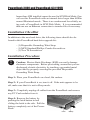
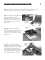
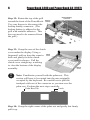
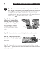
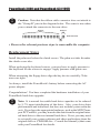
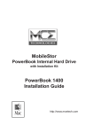
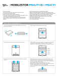
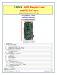
MobileStor
PowerBook Internal Hard Drive
with Installation Kit
Installation Guide
for
PowerBook 3400 and
PowerBook G3
http://www.mcetech.com
2
PowerBook 3400 and PowerBook G3 (1997)
Introduction to PowerBook 3400/G3 Installation
This chapter details the procedure for installing an MCE hard drive
upgrade kit into a PowerBook 3400 or the original PowerBook G3 (1997
release; a.k.a. Kanga).
!
Note: This section pertains to the PowerBook 3400 and PowerBook G3 model that have a multi-colored Apple logo both on the
outside of the top cover and below the display.
MCE strongly recommends that the installation be performed by a
qualified technician. The installation procedure involves disassembling
the PowerBook and exposing its sensitive electronics. This is a delicate
process and, if not performed properly, could cause damage to the
PowerBook. These installation instructions are given for those who
understand these risks. If performed correctly, these instructions will
guide an individual step-by-step through a successful installation of the
new hard drive.
The new hard drive comes formatted and initialized with a Macintosh
driver, but generally requires the installation of appropriate Macintosh
operating system (Mac OS) software for use in the PowerBook. You will
need a reliable Macintosh volume from which to boot the PowerBook in
order to load the necessary operating system software. Once the PowerBook is booted, the new hard drive will automatically mount onto the
PowerBook’s Desktop and is ready for software installation. If the drive
does not mount onto the Desktop, the PowerBook may prompt you to
initialize the hard drive upon startup, after which the drive should then
automatically mount onto your Desktop and be ready for software
installation.
See the PowerBook User’s Manual for operating system and other
software installation procedures.
!
Caution: Due to a bug in Apple’s ROM support for SCSI Disk
Mode, a PowerBook 3400/G3 which has an internal IDE hard drive
PowerBook 3400 and PowerBook G3 (1997)
3
larger than 4GB installed cannot be used in SCSI Disk Mode. One
can use this PowerBook with an internal drive larger than 4GBin
normal Macintosh mode. There is no workaround for reliably using such a PowerBook in SCSI Disk Mode. It is recommended
that one use an Ethernet connection to transfer files if necessary.
Installation Checklist
In addition to the new hard drive, the following items should also be
found in this PowerBook hard drive upgrade kit:
- (1) Disposable Grounding Wrist Strap
- (1) MCE Standard/Phillips Combo Screwdriver
- (1) Torx T8 Screwdriver
Installation Procedure
!
Caution: Electro-Static Discharge (ESD) can easily damage
electronic components. Before proceeding, ensure that you are
discharged of static electricity by touching a grounded metal
object and by properly securing the provided Disposable
Grounding Wrist Strap.
Step 1: Place your PowerBook on a hard, flat surface.
Step 2: If your PowerBook is on, turn it off. If the unit appears to be
off, make sure that it is not in Sleep mode.
Step 3: Completely unplug all cables from the PowerBook and remove
any PC Card modules from it.
Step 4: Remove the battery by
pushing the latch button in and
sliding the latch to the side. Pull the
battery completely out of the PowerBook.
Latch
Battery
4
PowerBook 3400 and PowerBook G3 (1997)
(Rear View)
Step 5: To remove the floppy/CDROM drive assembly without
damaging it, turn the unit upside
down as shown. Slide the release
button outward. Grasp the ridged
area of the plastics (not the metal
cover) to prevent bending the
metal top case and possibly
damaging the drive. Grasping the
assembly by its ridged area, pull it
out of the media bay.
Step 6: Close and latch the
PowerBook and turn it upside
down. Remove the 3 screws on
the bottom of the case with the
torx screwdriver.
!
Floppy
Drive
Assembly
Ridged Area
Release Button
Screw
Screw
Caution: If you pull the keyboard too far you will rip the
keyboard cables out of their connectors. Perform the next
steps slowly and carefully.
Step 7: Turn the PowerBook right-side-up, front facing you and lift
open the display. Rotate the
Speaker
display as far back as it will go
Grill
away from you, probably, around
170° from the base of the PowerBook. Using the small flat-blade
screwdriver to get underneath it,
lift the keyboard slightly up and
toward you until you feel a small
resistance (its four top interior tabs
should just clear the speaker grill).
STOP!
Screw
PowerBook 3400 and PowerBook G3 (1997)
Step 8: Gently rotate the top of the keyboard (the end closest to the
display) toward you, laying it face down onto the palm rest.
Step 9: Using the small flat-blade
screwdriver, detach the two
keyboard cables by gently lifting
up their respective connector ears.
Remove the keyboard, and set it
safely aside.
Keyboard Cable
Connectors
Keyboard
Turned Over
RAM Card
Step 10: If present, grasp the
RAM card by the corners closest to
you (supporting the bottom left
corner over the connector and lift
straight up.
Step 11: Carefully detach the
brightness & speaker cable from its
connector. Remove the screw from
the brightness and speaker grill.
Lift off the grill (the piece under the
up arrow in the picture) until you
feel a slight resistance. STOP!
Brightnes
& Speaker
Grill
Screw
5
6
PowerBook 3400 and PowerBook G3 (1997)
Step 12: Rotate the top of the grill
toward the front of the PowerBook.
Use your fingers to disconnect the
backup battery connector. (The
backup battery is adhered to the
grill with reusable adhesive. This
does not need to be removed from
the grill.)
Backup Battery
Connector
Backup
Battery
Step 13: Grasp the area of the clutch
cover under the display. Using a
fingernail, pull up from the seam in Clutch
Cover
back and gently rock the clutch
cover until it releases. Pull the
clutch cover straight up, watching
to clear the bottom of the display
assembly.
!
Clutch
Cover
Note: Familiarize yourself with the palm rest. This
section will have to be rotated into the area originally
occupied by the keyboard. Be carefull not to pull the
trackpad cable out of the connector as you turn over the
palm rest. Perform the next steps carefully.
Palm Rest Tab
Latch
Step 14: Grasp the right corner of the palm rest and gently but firmly
pull it up.
PowerBook 3400 and PowerBook G3 (1997)
7
Step 15: Referring to the latch noted on the previous diagram, use a
small flat-blade screwdriver to gently press the latch toward the palm rest
and at the same time rotate the top right section of the palm rest towards
the front of the PowerBook.
Step 16: Once the latch is freed, grasp the top right side of the palm rest
and pull it up slowly. Note that there are six more latches connecting the
palm rest, along the front and middle seams. Some of these latches may
be a bit tough to release, especially along the left front seam. You might
try gently rocking the palm rest to free these latches. You might also try
pushing with your thumbs on the bottom half of the case below the front
seam as you pull the top palm rest area with your other fingers.
Step 17: Rotate the palm rest
over until it is laying upside
down in the area that the keyboard originally occupied,
remembering not to pull the
trackpad cable out of the connector as you turn over the palm rest.
Step 18: Remove the three
interchangeable screws connecting the hard drive bracket to the
CPU stiffener. Lift up the bracket
until you feel a slight resistance STOP! Notice the hard drive
cable connecting the drive to the
logic board.
8
PowerBook 3400 and PowerBook G3 (1997)
!
Tip: There are two items that the bracket protects - the hard
drive and the power supply board underneath the right side of the
bracket. When separating the bracket from the computer use a
small flat-blade screwdriver to hold down the power supply
board. Do this by applying slight pressure to the right edge of the
board. Touch only the green part of the IC board.
Step 19: While holding the
power supply board in place
rotate the bracket towards the
front of the PowerBook. Disconnect the hard drive cable connector from the logic board by
carefully pulling up on the
hardened plastic back of the
cable.
Screw
Screw
Screw
Hard
Drive
Cable
Screw
Step 20: Remove the four screws holding the drive in the bracket.
Cable
Step 21: Remove the hard drive
from within the bracket. Use the pull
tabs to disconnect the cable from the
hard drive.
Pull
Tab
Step 22: Replace the cable connector onto the new hard drive taking
care to orient it properly for later connection of the other end of the cable
to the logic board.
PowerBook 3400 and PowerBook G3 (1997)
!
9
Caution: Note that the ribbon cable connector does not attach to
the “Group B” pins in the diagram below. The same is true when
you re-attach the connector to the new drive.
Group A
Group B
Hard Drive Pins
gap
• Reverse the relevant previous steps to reassemble the computer.
Replacement Notes
Install the palm rest before the clutch covers. The palm rest tabs fit under
the clutch cover tabs.
When replacing the keyboard screws, you may have to apply pressure to
the keyboard for the screws to engage. Apply pressure with great care.
When reinserting the floppy drive align the bay device carefully. Tolerances are tight.
As always, install the PowerBook’s battery before connecting the AC
power adapter.
Congratulations! You have completed the hardware installation of your
PowerBook hard drive upgrade.
!
Note: It is normal for usable hard drive capacities to be reduced
by 5-7% upon initialization of the drive. Also, your drive ships
preformatted and initialized, but does not include system software
on it. If you have the appropriate hardware, such as the MCE Transport PC Card Kit, you may transfer the data from the original internal hard drive to the new internal hard drive. If not, you may need
to re-install your system software and other applications from the
original disks or CD-ROM disc. Consult the manual(s) that came
with your PowerBook for details.
MobileStor Installation Guide
Limited Warranty
This is your MCE Technologies, LLC (MCE) three year limited warranty. The original purchaser (Purchaser) must present a dated proof of purchase (Bill of Sale) to obtain warranty service.
This product is warranted by MCE to be free from defects in material and workmanship for three (3) years
from the date of purchase by the Purchaser.
Purchaser's sole remedy under an MCE warranty shall be, at MCE's sole election, refund, repair or replacement as provided in this warranty. An MCE warranty shall not apply to any failure or defect caused
by misuse, abnormal use, neglect, abuse, alteration, improper installation, unauthorized repair or modification, improper testing, accident or causes external to the product such as but not limited to excessive
heat or humidity, power failure, or surges, or improper installation, or damage arising from improper
packaging during transport; and damage resulting from causes, including without limitation, lack of technical skill, competence, or experience of the user. This warranty shall not be enlarged, diminished or
affected by, and no liability shall arise out of, MCE's rendering of technical advice or providing information to Purchaser. Service by anyone other than MCE authorized service personnel voids any MCE
warranty. MCE makes no representations or warranties, express or implied, regarding the fitness of a
product for any particular purpose, or that a product is compatible with any particular hardware or software.
MCE's sole and exclusive maximum liability for any claim by Purchaser arising out of Purchaser's purchase of a product and/or the above warranty shall not in any event exceed the actual amount paid by
Purchaser for the product. In no event shall MCE be liable for any direct, indirect, incidental, collateral,
exemplary, consequential or special damages or losses arising out of Purchaser's purchase and/or use of
products, including, without limitation, loss of use, profits, goodwill or savings, or loss of data, data files,
or programs that may have been stored by a user of the product.
Continued use or possession of a product after expiration of its warranty period shall be conclusive evidence that the warranty is fulfilled to the full satisfaction of Purchaser.
MCE shall honor the terms of an MCE warranty as described herein, provided that the defective product
is sent in its original packaging to MCE, together with a copy of the dated proof of purchase on which the
product appears, transportation and insurance prepaid, within the warranty period, and if the product is
found by MCE to be defective within the terms of the warranty. Prior to returning any product to MCE,
Purchaser must obtain a Return Merchandise Authorization (RMA) number from MCE. No product shall
be accepted for return, repair or replacement without an RMA number visibly written on the outside of its
original packaging or comparable packaging affording an equal degree of protection. MCE shall not be
responsible for merchandise sent to MCE improperly packaged. Purchaser must prepay shipping charges
for merchandise shipped back to MCE for warranty service. Prior to returning the product, Purchaser
must, if possible, remove any and all programs and data from any storage media. Replacement products
and parts used to repair products may be similar new or other than new items. Replaced products and
parts shall become the property of MCE. If any product returned by Purchaser to MCE for repair or
replacement is not defective within this warranty, MCE shall so advise Purchaser and thereafter MCE
shall handle such products in accordance with Purchaser's instructions and at Purchaser's cost, after reimbursement to MCE by Purchaser of freight charges at then current rates, and examination and testing
expenses at then current rates ($60.00 per hour as of January 2001). Prices, terms and conditions are
subject to change without notice.
Non-defective purchases which are returned to MCE must be returned within thirty (30) days of purchase.
For non-defective purchases which are returned or refused by the Purchaser, MCE will, at its discretion,
issue a credit or refund for the purchase price of the goods, less all shipping charges incurred in the
shipment and a restocking fee of no less than fifteen percent (15%) of the retail price of the goods.
MCE Technologies, LLC
Irvine, California, USA
Technical Support
(949)458-0800
[email protected]
Sales
(800)500-0622
[email protected]
http://www.mcetech.com
Copyright © 2001 MCE Technologies, LLC. All rights reserved.
MCE, the MCE logo, and MobileStor are trademarks of MCE Technologies, LLC.
Apple, Mac, the Mac OS logo, Macintosh, PowerBook, iBook, and Drive
Setup are trademarks of Apple Computer, Inc. registered in the U.S. and
other countries.
Products and company names are trademarks of their respective companies, and are mentioned for informational purposes only and constitute
neither an endorsement nor a recommendation.
Every effort has been made to ensure that the information in this manual
is accurate. MCE Technologies, LLC is not responsible for printing or
clerical errors. Information in this document is subject to change without
notice and does not represent a commitment on the part of MCE Technologies, LLC.
Rev. 0328