1
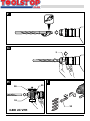
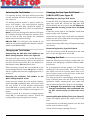
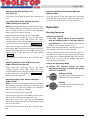
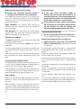
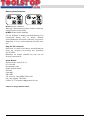
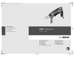
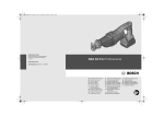
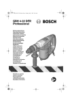
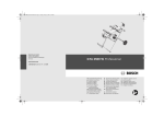
Robert Bosch GmbH
Power Tools Division
70745 Leinfelden-Echterdingen
www.bosch-pt.com
GBH Professional
1 619 929 740 (2007.07) O / 283
24 VFR | 24 VRE
de
en
fr
es
pt
it
nl
Originalbetriebsanleitung
Original instructions
Notice originale
Manual original
Manual original
Istruzioni originali
Oorspronkelijke
gebruiksaanwijzing
da Original brugsanvisning
sv Bruksanvisning i original
no Original driftsinstruks
fi Alkuperäiset ohjeet
el
tr
pl
cs
sk
hu
ru
uk
Πρωτότυπο οδηγιών χρήσης
Orijinal işletme talimat
Instrukcją oryginalną
Původním návodem k
používání
Pôvodný návod na použitie
Eredeti használati utasítás
Одлинник руководства по
эксплуатации
Оригінальна інструкція з
експлуатації
ro Instrucţiuni de folosire
originale
bg Оригинално ръководство
за експлоатация
sr Originalno uputstvo za rad
sl Izvirna navodila
hr Originalne upute za rad
et Algupärane kasutusjuhend
lv Instrukcijām
oriģinālvalodā
lt Originali
instrukcija
3|
A
B
15
11
14
C
x
13 12
5
D
1
4
E
17
18
3
16
GBH 24 VFR
1 619 929 740 | (24.7.07)
GBH 24 VRE
Bosch Power Tools
4|
F
G
3
H
I
21
20
RELEASE, AUF
19
GRIP, ZU
22
GBH 24 VFR
1 619 929 740 | (24.7.07)
Bosch Power Tools
5|
6
5
1
4
3
7
8
2
13 12
9
10
11
GBH 24 VFR
Professional
1 619 929 740 | (24.7.07)
Bosch Power Tools
English | 17
General Power Tool Safety
Warnings
en
Read all safety warnings and all
instructions. Failure to follow
the warnings and instructions may result in electric shock, fire and/or serious injury.
Save all warnings and instructions for future
reference.
The term “power tool” in the warnings refers to
your mains-operated (corded) power tool or
battery-operated (cordless) power tool.
WARNING
1) Work area safety
a) Keep work area clean and well lit. Cluttered or dark areas invite accidents.
b) Do not operate power tools in explosive
atmospheres, such as in the presence of
flammable liquids, gases or dust. Power
tools create sparks which may ignite the
dust or fumes.
c) Keep children and bystanders away
while operating a power tool. Distractions can cause you to lose control.
2) Electrical safety
a) Power tool plugs must match the outlet.
Never modify the plug in any way. Do not
use any adapter plugs with earthed
(grounded) power tools. Unmodified
plugs and matching outlets will reduce
risk of electric shock.
b) Avoid body contact with earthed or
grounded surfaces, such as pipes, radiators, ranges and refrigerators. There is
an increased risk of electric shock if your
body is earthed or grounded.
c) Do not expose power tools to rain or wet
conditions. Water entering a power tool
will increase the risk of electric shock.
d) Do not abuse the cord. Never use the
cord for carrying, pulling or unplugging
the power tool. Keep cord away from
heat, oil, sharp edges and moving parts.
Damaged or entangled cords increase the
risk of electric shock.
e) When operating a power tool outdoors,
use an extension cord suitable for outdoor use. Use of a cord suitable for outdoor use reduces the risk of electric shock.
Bosch Power Tools
f) If operating a power tool in a damp location is unavoidable, use a residual current device (RCD) protected supply. Use
of an RCD reduces the risk of electric
shock.
3) Personal safety
a) Stay alert, watch what you are doing and
use common sense when operating a
power tool. Do not use a power tool
while you are tired or under the influence of drugs, alcohol or medication. A
moment of inattention while operating
power tools may result in serious personal injury.
b) Use personal protective equipment. Always wear eye protection. Protective
equipment such as dust mask, non-skid
safety shoes, hard hat, or hearing protection used for appropriate conditions will
reduce personal injuries.
c) Prevent unintentional starting. Ensure
the switch is in the off-position before
connecting to power source and/or battery pack, picking up or carrying the
tool. Carrying power tools with your finger on the switch or energising power
tools that have the switch on invites accidents.
d) Remove any adjusting key or wrench before turning the power tool on. A wrench
or a key left attached to a rotating part of
the power tool may result in personal injury.
e) Do not overreach. Keep proper footing
and balance at all times. This enables
better control of the power tool in unexpected situations.
f) Dress properly. Do not wear loose clothing or jewellery. Keep your hair, clothing
and gloves away from moving parts.
Loose clothes, jewellery or long hair can
be caught in moving parts.
g) If devices are provided for the connection of dust extraction and collection facilities, ensure these are connected and
properly used. Use of dust collection can
reduce dust-related hazards.
1 619 929 740 | (24.7.07)
18 | English
4) Power tool use and care
a) Do not force the power tool. Use the correct power tool for your application. The
correct power tool will do the job better
and safer at the rate for which it was designed.
b) Do not use the power tool if the switch
does not turn it on and off. Any power
tool that cannot be controlled with the
switch is dangerous and must be repaired.
c) Disconnect the plug from the power
source and/or the battery pack from the
power tool before making any adjustments, changing accessories, or storing
power tools. Such preventive safety
measures reduce the risk of starting the
power tool accidentally.
d) Store idle power tools out of the reach of
children and do not allow persons unfamiliar with the power tool or these instructions to operate the power tool.
Power tools are dangerous in the hands of
untrained users.
e) Maintain power tools. Check for misalignment or binding of moving parts,
breakage of parts and any other condition that may affect the power tool’s operation. If damaged, have the power tool
repaired before use. Many accidents are
caused by poorly maintained power tools.
f) Keep cutting tools sharp and clean. Properly maintained cutting tools with sharp
cutting edges are less likely to bind and
are easier to control.
g) Use the power tool, accessories and tool
bits etc. in accordance with these instructions, taking into account the working conditions and the work to be performed. Use of the power tool for
operations different from those intended
could result in a hazardous situation.
5) Battery tool use and care
a) Recharge only with the charger specified
by the manufacturer. A charger that is
suitable for one type of battery pack may
create a risk of fire when used with another battery pack.
1 619 929 740 | (24.7.07)
b) Use power tools only with specifically
designated battery packs. Use of any other battery packs may create a risk of injury
and fire.
c) When battery pack is not in use, keep it
away from other metal objects, like paper clips, coins, keys, nails, screws or
other small metal objects, that can make
a connection from one terminal to another. Shorting the battery terminals together may cause burns or a fire.
d) Under abusive conditions, liquid may be
ejected from the battery; avoid contact.
If contact accidentally occurs, flush with
water. If liquid contacts eyes, additionally seek medical help. Liquid ejected from
the battery may cause irritation or burns.
6) Service
a) Have your power tool serviced by a qualified repair person using only identical
replacement parts. This will ensure that
the safety of the power tool is maintained.
Machine-specific
Safety Warnings
f Wear hearing protection. Exposure to noise
can cause hearing loss.
f Always use the auxiliary handle supplied
with the machine. Loss of control can cause
personal injury.
f Use appropriate detectors to determine if
utility lines are hidden in the work area or
call the local utility company for assistance.
Contact with electric lines can lead to fire
and electric shock. Damaging a gas line can
lead to explosion. Penetrating a water line
causes property damage or may cause an
electric shock.
f Hold the machine only by the insulated gripping surfaces, when performing an operation where the cutting tool may run into hidden wiring. Contact with a “live” wire will
make exposed metal parts of the tool “live”
and shock the operator.
Bosch Power Tools
English | 19
f When working with the machine, always
hold it firmly with both hands and provide
for a secure stance. The power tool is guided
more secure with both hands.
f Secure the workpiece. A workpiece clamped
with clamping devices or in a vice is held
more secure than by hand.
f Do not work materials containing asbestos.
Asbestos is considered carcinogenic.
f Take protective measures when dust can
develop during working that is harmful to
one’s health, combustible or explosive. Example: Some dusts are regarded as carcinogenic. Wear a dust mask and work with
dust/chip extraction when connectable.
f Keep your workplace clean. Blends of materials are particularly dangerous. Dust from
light alloys can burn or explode.
f Always wait until the machine has come to
a complete stop before placing it down. The
tool insert can jam and lead to loss of control
over the power tool.
f Avoid unintentional switching on. Ensure
the On/Off switch is in the off position before inserting battery pack. Carrying the
power tool with your finger on the On/Off
switch or inserting the battery pack into
power tools that have the switch on invites
accidents.
f Do not open the battery. Danger of shortcircuiting.
Protect the battery against heat, e. g.,
also against continuous sun irradiation and fire. There is danger of explosion.
Functional Description
Read all safety warnings and all instructions. Failure to follow the
warnings and instructions may result in electric shock, fire and/or serious injury.
Intended Use
The machine is intended for hammer drilling in
concrete, brick and stone. It is also suitable for
drilling without impact in wood, metal, ceramic
and plastic. Machines with electronic control
and right/left rotation are also suitable for
screwdriving and thread cutting.
Product Features
The numbering of the product features refers to
the illustration of the machine on the graphics
page.
1 SDS-plus tool holder
2 Dust protection cap
3 Locking sleeve
4 Lock ring of the tool holder (GBH 24 VFR)
5 Button for depth stop adjustment
6 Selector switch for drilling/hammer drilling
7 Rotational direction switch
8 On/Off switch
9 Button for charge-control indicator
10 Battery charge-control indicator
11 Battery*
12 Auxiliary handle
13 Depth stop
14 Battery release button*
15 Protection cap for battery
16 Securing screw for key type drill chuck*
17 Key type drill chuck*
18 SDS-plus adapter shank for drill chuck*
19 Quick change keyless chuck (GBH 24 VFR)
20 Front sleeve of the quick change keyless
chuck (GBH 24 VFR)
21 Retaining ring of the quick change keyless
chuck (GBH 24 VFR)
22 Universal bit holder with SDS-plus shank*
*The accessories illustrated or described are not included as standard delivery.
While reading the operating instructions, unfold
the graphics page for the machine and leave it
open.
Bosch Power Tools
1 619 929 740 | (24.7.07)
20 | English
Technical Data
Rotary Hammer
GBH 24 VFR
Professional
GBH 24 VFR
Professional
GBH 24 VRE
Professional
GBH 24 VRE
Professional
0 611 260 5..
0 611 261 7..
0 611 261 5..
0 611 260 7..
Rated voltage
V=
24
24
24
24
Rated power input
W
350
350
350
350
Rated speed
rpm
0–1000
0–1000
0–1000
0–1000
Impact rate
bpm
0–4400
0–4400
0–4400
0–4400
Article number
J
1.3
1.3
1.3
1.3
SDS-plus
SDS-plus
SDS-plus
SDS-plus
mm
mm
mm
20
10
20
20
10
20
20
10
20
20
10
20
kg
3.5
4.2
3.5
4.2
Impact energy per stroke
Tool holder
Max. drilling dia.
– Concrete (with twist drill)
– Steel
– Wood
Weight according to
EPTA-Procedure 01/2003
Please observe the article number on the type plate of your machine. The trade names of the individual machines may vary.
Noise/Vibration Information
Measured values determined according to
EN 60745.
Typically the A-weighted noise levels of the
product are: Sound pressure level 91 dB(A);
Sound power level 102 dB(A). Uncertainty
K =3 dB.
Wear hearing protection!
Vibration total values (triax vector sum) determined according to EN 60745:
Hammer drilling into concrete: Vibration emission value ah =12 m/s2, Uncertainty K=1.5 m/s2.
The vibration emission level given in this information sheet has been measured in accordance
with a standardised test given in EN 60745 and
may be used to compare one tool with another.
It may be used for a preliminary assessment of
exposure.
The declared vibration emission level represents the main applications of the tool. However
if the tool is used for different applications, with
different accessories or poorly maintained, the
vibration emission may differ. This may significantly increase the exposure level over the total
working period.
1 619 929 740 | (24.7.07)
An estimation of the level of exposure to vibration should also take into account the times
when the tool is switched off or when it is running but not actually doing the job. This may significantly reduce the exposure level over the total working period.
Identify additional safety measures to protect
the operator from the effects of vibration such
as: maintain the tool and the accessories, keep
the hands warm, organisation of work patterns.
Declaration of Conformity
We declare under our sole responsibility that
the product described under “Technical Data” is
in conformity with the following standards or
standardization documents: EN 60745 according to the provisions of the directives
2004/108/EC, 98/37/EC (until Dec. 28, 2009),
2006/42/EC (from Dec. 29, 2009 on).
Technical file at:
Robert Bosch GmbH, PT/ESC,
D-70745 Leinfelden-Echterdingen
Bosch Power Tools
English | 21
Dr. Egbert Schneider
Senior Vice President
Engineering
Dr. Eckerhard Strötgen
Head of Product
Certification
0 – 10 %
10 – 20 %
20 – 40 %
40 – 60 %
29.06.2007, Robert Bosch GmbH, Power Tools Division
D-70745 Leinfelden-Echterdingen
60 – 80 %
80 – 100 %
Assembly
f Before any work on the machine (e. g.,
maintenance, tool change, etc.) as well as
during transport and storage, set the rotational direction switch to the centre position. Unintentional actuation of the On/Off
switch can lead to injuries.
Battery Charging
A battery that is new or has not been used for a
longer period does not develop its full capacity
until after approx. 5 charging/discharging cycles.
To remove the battery 11, press the battery release button 14 and pull the battery downward
out of the power tool. Do not exert any force.
(see figure A)
The battery is equipped with a NTC temperature
control which allows charging only within a temperature range of between 0 °C and 45 °C. A
long battery service life is achieved in this manner.
A significantly reduced working period after
charging indicates that the battery is used and
must be replaced.
Observe the notes for disposal.
Battery Charge-control Indication
The battery charge-control indicator 10 indicates the charge condition of the battery 11 during the working procedure.
Push button 9 to indicate the charge condition
when the battery is removed or when the power
tool is switched off. The battery charge-control
indicator automatically goes out after approx.
5 seconds.
Bosch Power Tools
When the first indicator element (0 – 10%)
flashes, the battery is almost completely discharged and must be recharged again.
Discharge the battery occasionally until the
speed of the power tool reduces significantly
and the battery charge-control indicator 10
completely goes out. Frequent charging after
short-term usage impairs the indication accuracy and the service life of the battery.
Auxiliary Handle
f Operate your machine only with the auxiliary handle 12.
The auxiliary handle 12 can be set to any position
for a secure and low-fatigue working posture.
Turn the bottom part of the auxiliary handle 12
in counterclockwise direction and swivel the
auxiliary handle 12 to the desired position. Then
retighten the bottom part of the auxiliary handle
12 by turning in clockwise direction.
Adjusting the Drilling Depth (see figure C)
The required drilling depth X can be set with the
depth stop 13.
Press the button for the depth stop adjustment
5 and insert the depth stop into the auxiliary
handle 12.
Insert the SDS-plus drilling tool to the stop into
the SDS-plus tool holder 1. Otherwise, the movability of the SDS-plus drilling tool can lead to
incorrect adjustment of the drilling depth.
Pull out the depth stop until the distance between the tip of the drill bit and the tip of the
depth stop correspond with the desired drilling
depth X.
The knurled surface of the depth stop 13 must
face upward.
1 619 929 740 | (24.7.07)
22 | English
Selecting the Tool Holder
For hammer drilling, SDS-plus drilling tools that
can be inserted into the SDS-plus tool holder 1
are required.
For drilling without impact in wood, metal, ceramic and plastic, use non-SDS-plus drilling
tools (e. g. drill bits with cylindrical shank). A
keyless or a key type drill chuck is required for
such drilling tools.
Note: Do not use drilling tools without SDS-plus
for hammer drilling! Drilling tools without SDSplus as well as the tool holder are damaged
when used for hammer drilling.
GBH 24 VFR: The SDS-plus tool holder 1 can
easily be exchanged against the keyless replacement chuck 19 provided.
Changing the Tool Holder
Dismounting the SDS-plus Tool Holder or the
Quick change keyless chuck (see figure D)
Changing the Key Type Drill Chuck
(GBH 24 VRE) (see figure E)
Mounting the Key Type Drill Chuck
Screw the SDS-plus adapter shank 18 into a key
type drill chuck 17. Secure the key type drill
chuck 17 with the securing screw 16. Please observe that the securing screw has a left-hand
thread.
Clean the shank end of the adapter shank and
apply a light coat of grease.
Insert the key type drill chuck with the adapter
shank into the tool holder with a turning motion
until it automatically locks.
Check the locking effect by pulling the key type
drill chuck.
Dismounting the Key Type Drill Chuck
Push the locking sleeve 3 toward the rear and
pull out the key type drill chuck 17.
Pull the lock ring of the tool holder 4 firmly in
the direction of the arrow, hold it in this position
and pull off the tool holder 1 or the keyless replacement chuck 19 toward the front.
Changing the Tool
After removing, protect the tool holder 1 or the
quick change keyless chuck 19 against contamination. Lightly lubricate the engaging grooves, if
required.
As a requirement of the system, the SDS-plus
drilling tool can move freely. This causes a certain radial run-out at no-load, which has no effect on the accuracy of the drill hole, as the drill
bit centres itself upon drilling.
Mounting the SDS-plus Tool Holder or the
Quick change keyless chuck
Grasp the tool holder 1 or the keyless replacement chuck 19 completely with your hand. Slide
the tool holder 1 or the keyless replacement
chuck 19 with a turning motion onto the drill
chuck mounting until a distinct latching noice is
heard.
The tool holder 1 or the quick change keyless
chuck 19 is automatically locked. Check the
locking effect by pulling the tool holder.
With the SDS-plus tool holder, simple and convenient tool changing is possible without additional aids.
The dust protection cap 2 largely prevents the
entry of drilling dust into the tool holder during
operation. When inserting the tool, take care
that the dust protection cap 2 is not damaged.
f A damaged dust protection cap should be
changed immediately. We recommend having this carried out by an after-sales service.
Inserting SDS-plus Drilling Tools (see figure F)
Clean and lightly grease the shank end of the
tool.
Insert the tool in a twisting manner into the tool
holder until it latches itself.
Check the latching by pulling the tool.
1 619 929 740 | (24.7.07)
Bosch Power Tools
English | 23
Removing SDS-plus Drilling Tools
(see figure G)
Removing Drilling Tools without SDS-plus
(GBH 24 VRE)
Push back the locking sleeve 3 and remove the
tool.
Turn the sleeve of the key type drill chuck 17
with the drill chuck key in anticlockwise direction until the drilling tool can be removed.
Inserting Drilling Tools without SDS-plus
(GBH 24 VFR) (see figure H)
Note: Do not use drilling tools without SDS-plus
for hammer drilling! Drilling tools without SDSplus as well as the tool holder are damaged
when used for hammer drilling.
Insert the quick change keyless chuck 19.
Firmly hold the retaining ring of the quick
change keyless chuck 19. Open the quick
change keyless chuck by turning the front sleeve
in the direction of the symbol “
”.
Insert the drilling tool into the quick change keyless chuck 19. Firmly hold the retaining ring of
the quick change keyless chuck 19 and turn the
front sleeve in the direction of the symbol
“
”.
Set the selector switch 6 to the “Drilling” symbol.
Removing Drilling Tools without SDS-plus
(GBH 24 VFR) (see figure H)
Firmly hold the retaining ring of the quick
change keyless chuck 19. Open the quick
change keyless chuck by turning the front sleeve
in the direction of the symbol “
”.
Remove the drilling tool.
Inserting Drilling Tools without SDS-plus
(GBH 24 VRE)
Note: Do not use drilling tools without SDS-plus
for hammer drilling! Drilling tools without SDSplus as well as the tool holder are damaged
when used for hammer drilling.
Operation
Starting Operation
Inserting the Battery
f Use only original Bosch O-pack batteries
with the voltage given on the type plate of
your machine. The use of other batteries can
lead to injuries and danger of fire.
Before inserting the battery, remove the protection cap 15, if required. (see figure B)
Set the rotational direction switch 7 to the centre position in order to avoid unintentional starting. Insert the charged battery 11 into the handle so that it can be felt to engage and faces
flush against the handle.
Setting the Operating Mode
f Actuate the selector switch for drilling/hammer drilling 6 only when the power
tool is at a standstill.
Hammer drilling
Set the selector switch 6 to the
“Hammer drilling” symbols.
Drilling
Set the selector switch 6 to the
“Drilling” symbol.
Insert the key type drill chuck 17.
Open the key type drill chuck 17 by turning until
the tool can be inserted. Insert the tool.
Insert the chuck key into the corresponding
holes of the key type drill chuck 17 and clamp
the tool uniformly.
Set the selector switch 6 to the “Drilling” symbol.
Bosch Power Tools
1 619 929 740 | (24.7.07)
24 | English
Reversing the Rotational Direction
Overload Clutch
f Actuate the rotational direction switch 7
only when the machine is at a standstill.
f If the tool insert becomes caught or
jammed, the drive to the drill spindle is interrupted. Because of the forces that occur,
always hold the power tool firmly with both
hands and provide for a secure stance.
The rotational direction switch 7 is used to reverse the rotational direction of the machine.
However, this is not possible with the On/Off
switch 8 actuated.
Right Rotation: For drilling and driving in
screws, push the rotational direction switch 7
left to the stop.
Left Rotation: For loosening and unscrewing
screws and nuts, press the rotational direction
switch 7 through to the right stop.
Switching On and Off
To start the machine, press the On/Off switch 8
and keep it depressed.
To switch off the machine, release the On/Off
switch 8.
For low temperatures, the machine reaches the
full hammer/impact capacity only after a certain
time.
This start-up time can be shortened by striking
the inserted tool insert against the floor one
time.
Setting the Speed/Impact Rate
The speed/impact rate of the switched on power tool can be variably adjusted, depending on
how far the On/Off switch 8 is pressed.
Light pressure on the On/Off switch 8 results in
low speed/impact rate. Further pressure on the
switch increases the speed/impact rate.
f If the power tool jams, switch the machine
off and loosen the tool insert. When switching the machine on with the drilling tool
jammed, high reaction torques can occur.
Operating Instructions
f Do not operate the power tool stationary. It
is not designed for operation in a drill stand.
Inserting Screwdriver Bits (see figure I)
f Apply the power tool to the screw/nut only
when it is switched off. Rotating tool inserts
can slip off.
To work with screwdriver bits, a universal bit
holder 22 with SDS-plus shank (accessory) is required.
Clean the shank end of the adapter shank and
apply a light coat of grease.
Insert the universal bit holder with a turning motion into the tool holder until it automatically
locks.
Check the locking effect by pulling the universal
bit holder.
Insert a screwdriver bit into the universal bit
holder. Use only screwdriver bits that match the
screw head.
Run-on Brake
Set the selector switch 6 to the “Drilling” symbol.
When the On/Off switch 8 is released, the chuck
brakes to a stop, thus preventing the run-on of
the tool.
To remove the universal bit holder, pull the locking sleeve 3 toward the rear and remove the universal bit holder 22 out of the tool holder.
When driving in screws, wait until the screw is
screwed in flush with the material and then release the On/Off switch 8. By doing so, the head
of the screw does not penetrate into the material.
1 619 929 740 | (24.7.07)
Bosch Power Tools
English | 25
Maintenance and Service
Maintenance and Cleaning
f Before any work on the machine (e. g.,
maintenance, tool change, etc.) as well as
during transport and storage, set the rotational direction switch to the centre position. Unintentional actuation of the On/Off
switch can lead to injuries.
f For safe and proper working, always keep
the machine and ventilation slots clean.
f A damaged dust protection cap should be
changed immediately. We recommend having this carried out by an after-sales service.
If the machine should fail despite the care taken
in manufacturing and testing procedures, repair
should be carried out by an after-sales service
centre for Bosch power tools.
In all correspondence and spare parts order,
please always include the 10-digit article
number given on the type plate of the machine.
After-sales service and customer
assistance
Our after-sales service responds to your questions concerning maintenance and repair of your
product as well as spare parts. Exploded views
and information on spare parts can also be
found under:
www.bosch-pt.com
Our customer consultants answer your questions concerning best buy, application and adjustment of products and accessories.
Great Britain
Robert Bosch Ltd. (B.S.C.)
P.O. Box 98
Broadwater Park
North Orbital Road
Denham
Uxbridge
UB 9 5HJ
Tel. Service: +44 (0844) 736 0109
Fax: +44 (0844) 736 0146
E-Mail: [email protected]
Bosch Power Tools
Ireland
Origo Ltd.
Unit 23 Magna Drive
Magna Business Park
City West
Dublin 24
Tel. Service: +353 (01) 4 66 67 00
Fax: +353 (01) 4 66 68 88
Australia, New Zealand and Pacific Islands
Robert Bosch Australia Pty. Ltd.
Power Tools
Locked Bag 66
Clayton South VIC 3169
Customer Contact Center
Inside Australia:
Phone: +61 (01300) 307 044
Fax: + 61 (01300) 307 045
Inside New Zealand:
Phone: +64 (0800) 543 353
Fax: +64 (0800) 428 570
Outside AU and NZ:
Phone: +61 (03) 9541 5555
www.bosch.com.au
Disposal
The machine, accessories and packaging should
be sorted for environmental-friendly recycling.
Only for EC countries:
Do not dispose of power tools into household waste!
According the European Guideline
2002/96/EC for Waste Electrical
and Electronic Equipment and its
implementation into national
right, power tools that are no longer usable
must be collected separately and disposed of in
an environmentally correct manner.
1 619 929 740 | (24.7.07)
26 | English
Battery packs/batteries:
Ni-Cd: Nickel cadmium
Warning: These battery packs contain cadmium,
a highly toxic heavy metal.
Ni-MH: Nickel metal hydride
Do not dispose of battery packs/batteries into
household waste, fire or water. Battery
packs/batteries should be collected, recycled or
disposed of in an environmental-friendly manner.
Only for EC countries:
Defective or dead out battery packs/batteries
must be recycled according the guideline
91/157/EEC.
Batteries no longer suitable for use can be
directly returned at:
Great Britain
Robert Bosch Ltd. (B.S.C.)
P.O. Box 98
Broadwater Park
North Orbital Road
Denham
Uxbridge
UB 9 5HJ
Tel. Service: +44 (0844) 736 0109
Fax: +44 (0844) 736 0146
E-Mail: [email protected]
Subject to change without notice.
1 619 929 740 | (24.7.07)
Bosch Power Tools