1
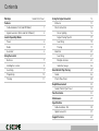
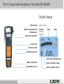
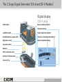
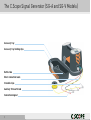
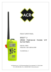
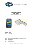
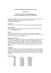
Instruction Manual
Cable Avoidance Tool
Cable Avoidance Tool XD
Signal Generator SG-A
Signal Generator SG-V
CABLE AVOIDANCE TOOLS
WARNINGS
The C.Scope Cable Avoidance Tools locate services radiating a detectable field.
There may be some services that do not radiate and cannot be located.
ALWAYS
EXCAVATE
WITH CARE
Do not use the equipment outside of the temperature range -10˚C to +50˚C as the
batteries may cease to function adequately.
Geographical conditions such as hills and mountains can effectively screen radio
signals and prevent a detectable ground current.
The C.Scope Cable Avoidance Tool alone will not always locate every conductor so
always use a Signal Generator.
The C.Scope Signal Generator leads must not be connected directly to a live service.
System performance may be impaired by unusually strong electromagnetic fields.
Beware of multiple services. The C.Scope Cable Avoidance Tool will not always
indicate close services, either side by side or one above the other.
Do not use the equipment in areas where hazardous gases may be present.
Check for underground services before using the earth stake.
Copyright © 2004 C.Scope International Ltd. All Rights Reserved.
C.Scope International Ltd make every effort to ensure that the information we provide about our products and their use is correct. We do not accept responsibility for
injury, damage, or consequential loss arising from the use of our products. Local, national and international requirements and regulations must take preference.
Contents
Warnings
Inside Front Cover
Features
Using the Signal Generator
12
Batteries
13
Cable Avoidance Tool (and XD Model)
1
Direct connection
14
Signal Generator (SG-A and SG-V Models)
2
Street lighting
16
Locator Operating Modes
Signal Clamp/ Injector
17
Power
4
Searching
18
Radio
5
Tracing
19
Generator
6
Using the Locator
Induction
20
Searching
21
Batteries
7
Multiple Services
23
Holding the Locator
8
Inductive Sweep
24
Searching
9
Non-Metallic Pipe Tracing
25
Pinpointing
10
Sonde
26
Tracing
11
Plastic Pipe Tracer
28
Depth Measurement
Sonde/ Plastic Pipe Tracer
30
32
Function checks
33
Maintenance
37
Specifications
Cable Avoidance Tool
Signal Generator
Support Services
38
39
40
The C.Scope Cable Avoidance Tool (And XD Model)
Digital display
Digital display
Depth measurement button
(XD model only)
Mode selected:
Generator
(showing
frequency)
Power
Radio
Detachable loud speaker
On/ Off switch
Sensitivity control
3 position mode switch
Depth display (XD Model only)
1
Battery compartment
Signal strength bar display
Replaceable wear foot
Battery condition indicator
The C.Scope Signal Generator (SG-A and SG-V Models)
Digital display
(SG-V only)
On/Off switch
Battery condition indicator
Mute/loud setting
Loud/Mute switch
Power output level indicator
Pulsed/Continuous output switch
Induced or connected mode indicator
High power switch
Signal strength bar display
Low power switch
Batteries
Direct connection socket
Auxiliary earth lead socket
Accessory tray
2
The C.Scope Signal Generator (SG-A and SG-V Models)
Accessory tray
Accessory tray holding clips
Earth stake
Direct connection leads
Crocodile clips
Auxiliary 10m earth lead
Connection magnet
3
Locator Operating Modes: Power Mode
In Power Mode the locator detects power signals. These power signals are present on all current carrying electricity
cables although not all are detectable. These power signals may also flow along other buried conductors such as metal
gas and water pipes.
Limitations of Power Mode
Not all electricity cables can be found using the Power mode. Here are the most important examples of
electricity cables that may not be detectable in the Power mode:
●
●
●
●
●
Street lighting cables. When the lights are off, no current flows and so no power signal is created.
Supplies to buildings or plant using very little or no electricity will not have a detectable power signal.
Pot-ended or capped cables. These will never have any current flowing through them but are possibly still live.
Disused or abandoned cables.
A few high voltage electricity cables. These can be “well balanced”, electrically and therefore radiate little
or no Power signal.
● Direct current cables (such as those found on railway systems). These do not create their own Power signals.
● Cables more than 3 metres deep.
WARNING Locators can only detect services radiating a detectable electromagnetic signal.
There may be some services that do not radiate these signals and cannot be located.
WARNING Absence of Power signal does not mean the service is not live.
NOTE Generally these services should be detectable using the Radio or Generator modes.
4
Locator Operating Modes: Radio Mode
In Radio mode, the locator detects signals from radio transmitters. These signals flow through the ground and will tend to
follow the line of least resistance such as a buried metallic service. When this happens the service can often be detected
by using the locator in Radio mode.
Limitations of Radio Mode
● Not all services will be detectable in Radio mode.
● A strong Radio signal present on one service may be masking a weaker Radio signal present on an adjacent service.
● It is not normally possible to determine WHAT the service is in Radio mode, only it’s position.
● Radio signals do not favour one utility over another.
● The depth of the buried service CANNOT be judged by the strength of the radio signal alone.
● Normally it is only possible to detect Radio signals present on services up to 2 metres deep.
● A short service may not have enough signal to be detected.
WARNING Locators can only detect services radiating a detectable electromagnetic signal.
There may be some services that do not radiate these signals and cannot be located.
NOTE Most buried metallic services not found in Radio mode should be detectable by using Generator
mode with a Signal Generator.
5
Locator Operating Modes: Generator Mode
In Generator mode the locator detects conductors radiating a
signal applied by the Signal Generator. The Signal Generator
provides a way of sending a known signal along buried metallic
services which can then be detected using the locator.
Direct Connection
By detecting this signal it is possible to locate, trace and
identify the pipes or cables that may be carrying it.
There are TWO basic methods by which the Signal Generator
signal can be applied to buried services:
Direct Connection - The Signal Generator is attached directly
to the service using either the Direct Connection Leads or one
of the accessories available for use with the Signal Generator
such as the Signal Clamp of Signal Injector.
Induction
Induction - The Signal Generator can induce a signal onto a
buried metallic service remotely from the surface without the
need to physically connect to that service.
Limitations of Generator Mode are covered in Using the ‘Signal
Generator’ section of this manual.
WARNING Locators can only detect services radiating a detectable electromagnetic signal.
There may be some services that do not radiate these signals and cannot be located.
6
Using the Locator: Batteries
Locator Battery Check
Switch the locator on by pulling up on the On/Off trigger positioned
on the underside of the handle. The locator should emit a clear audible
battery check tone for one second and the display should come on.
Battery levels
Check the battery level indicator in the bottom left hand corner of the
display. If there is only one segment or no segments of the indicator
filled in then the batteries will need to be renewed before locating work
can begin.
Changing Locator Batteries
Push the two clips back to release the battery compartment door. Remove ALL EIGHT used batteries and replace with
new ones. Be careful to insert the new batteries the correct way round in the holder. Replace the holder in the battery
compartment making sure that the two terminals on the holder make contact with the two terminals within the battery
compartment. Close the battery compartment door securely.
NOTE Only use alkaline AA (LR6) size batteries. Dispose of the used batteries safely in accordance with local
regulations.
WARNING Do not change batteries in confined spaces where gas may be present.
7
Using the Locator: Holding the Locator
When in use the locator should always be held upright.
NEVER swing the locator such that it moves away from
the vertical.
Your middle or little finger should be used to squeeze, and
hold on, the On/Off trigger.
Your index finger will then be free to adjust the sensitivity control.
8
Using the Locator: Searching
There are three stages to the locating process; searching, pinpointing and
tracing
1. Turn the function switch to the appropriate mode
2. Hold in the On/Off trigger. The locator should emit the audible battery
test tone and the digital display should come on. Check the battery level
indicator to confirm the batteries are usable.
3. Rotate the Sensitivity control clockwise to its maximum setting as
indicated by the arrow on the control.
4. Carry out the search using a grid pattern as shown in the diagram.
Walk slowly and keep the locator upright at all times and stationary by
your side.
5. As you approach the area in which there is a signal the locator will emit
an audible response and show a visual response on the bar display.
6. Keep walking until the audible and visual responses disappear.
NOTE This search technique applies only to the Power and Radio
modes. See ‘Using the Signal Generator’ for the correct search
pattern when using Generator mode.
NOTE Sometimes the locator will give an audible response and
strong (full scale) visual response across the whole of the search
area. In this case turn the sensitivity down slightly and repeat the
search using the same grid pattern.
9
Using the Locator: Pinpointing
Having found the presence of a signal the next stop is to pinpoint
the source. The closer the locator is to the signal source the
stronger the response.
To Pinpoint a Signal
1. Keeping the locator vertical, walk through the area of the signal
response. If the visual response goes off the scale then stop,
reduce the sensitivity of the locator slightly before continuing.
2. The width of the signal response will begin to shrink as the
sensitivity is reduced. Once the sensitivity is reduced enough then a
clear peak response will be seen on the bar display as the locator
traverses the service. The locator is positioned directly above the
buried service when the bar display is at its highest (peak) reading.
3. Carefully rotate the locator over the peak reading until the visual
response falls to a minimum level. The locator will now be roughly
IN LINE with the direction of the buried service.
4. Mark the position of the buried service.
NOTE The amount of sensitivity adjustment needed to pinpoint a service can vary depending on the mode being
used, the signal strength and the service depth.
10
Using the Locator: Tracing
Having pinpointed a service it should now be possible to trace it’s route.
1. Carefully follow the direction of the signal holding the locator at right angles
to the line of the signal. It is necessary to constantly ‘slice’ the locator from side
to side in order to be sure of still being over the peak signal response.
2. Stop and mark the position of the signal at regular intervals. As more marks
are recorded the precise direction of the service will become more apparent.
NOTE It may be necessary to readjust the sensitivity to maintain the
optimum response.
NOTE After tracing return to the original search grid to search for
further buried services.
WARNING Never rush the tracing process. Small and unexpected changes in the service’s route will be missed if
care is not taken to follow the signal’s path every step of the way.
Lost Signals
This can be because of a curve, or bend in the route, change in depth of the
service, a T connection or the end of the service.
Finding Lost Signals
1. Locate in a circle at least 1metre around the point where the signal was lost.
This should locate the service if it has simply changed direction sharply or ‘T’d’
into another service.
2. If you find nothing then increase the sensitivity and repeat the circle. This
should find the service if it has continued but at a greater depth.
11