1
Operator's Manual
12.5 Horse Power
36-inch Wide Cut Mower
Model No. 247.887360
CAUTION: Before using
this product, read this
manual and follow all
For answers to your questions
about this product, call:
Safety
Assembly
Operation
Maintenance
Parts
1-800-659-5917
Espahol, p.60
Safety Rules and
Operating Instructions.
Sears Craftsman
Help Line
5 a.m. - 5 p.m., Mon - Sat
Sears, Roebuck and Co., Hoffman
Estates, IL 60179, U.S.A.
Visit our Sears website: www.sears.com/craftsman
Printed in U.S.A.
FORM NO. 02005403 Rev 09_0
(4/2009)
WarrantyStatement
SafetyInstructions
SlopeGuide
RepairProtection
Agreement
SafetyLabels
ProductSpecification
Assembly
Operation
Craftsman
2
3
6
7
8
10
11
12
Maintenance
ServiceandAdjustments
Off-Season
Storage
Accessories
andAttachments
Troubleshooting
PartsList
Espanol
Two Year Limited Warranty
17
21
24
24
25
26
60
on 36-inch Wide Cut Mower
When used and maintained according to all supplied instructions, if this Craftsman product fails due to a defect in
material within two years from the date of purchase, return it to any Sears store, Parts & Repair Service Center, or
other Craftsman outlet in the United States for free repair. In-home warranty service is available, but you will have
to pay a trip charge.
This Warranty does not cover:
•
Expendable items which become worn during normal use, such as rotary mower blades, blade adaptors,
spark plugs, air cleaners, belts, and oil filters.
•
Tire replacement or repair caused by punctures from outside objects, such as nails, thorns, stumps, or glass.
•
Repairs necessary because of operator abuse, including but not limited to, damage caused by objects, such
as stones, metal debris or oversized pieces of wood, or impacting objects that bend the frame or crankshaft,
or over-speeding the engine.
•
Repairs necessary because of operator negligence, including but not limited to, electrical and mechanical
damage caused by improper storage, failure to use the proper grade and amount of engine oil, or failure to
maintain the equipment according to the instructions contained in the operator's manual.
•
Engine (fuel system) cleaning or repairs caused by fuel determined to be contaminated or oxidized (stale). In
general, fuel should be used within 30 days of its purchase date.
This warranty applies for only 90 days if this product is ever used for commercial or rental purposes.
This warranty applies only while this product is used in the United States.
This warranty gives you specific legal rights and you may also have other rights, which vary from state to state.
Sears, Roebuck and Co., Hoffman Estates, IL 60179
MODEL NUMBER
Model Number .........................................................
Serial Number ...........................................................
Date of Purchase ......................................................
Record the model number, serial number and date of
purchase above.
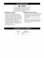
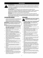
WARNING:
This symbol points out important safety instructions which, if not followed, could
endanger the personal safety and/or property of yourself and others. Read and follow all
instructions in this manual before attempting to operate this machine. Failure to comply with these
instructions may result in personal injury. When you see this symbol - heed its warning.
WARNING:
Engine Exhaust,
some of its constituents,
components contain or emit chemicals
and birth defects or other reproductive
DANGER:
and certain vehicle
known to State of California to cause cancer
harm.
This machine was built to be operated according to the rules for safe operation in this
manual. As with any type of power equipment, carelessness or error on the part of the operator can
result in serious injury. This machine is capable of amputating hands and feet and throwing objects.
Failure to observe the following safety instructions could result in serious injury or death.
GENERAL
1.
OPERATION
Read this Operator's Manual completely before
starting the mower. Study the controls and learn
the proper sequence of operation. Retain
Operator's Manual in a safe place for future
reference.
operator
English
or
WARNING:
Never mow in fifth gear I
(transport speed).
2.
Spanish,
the owner
for read
explaining the
IMPORTANT:
If the is responsible
cannot
information in this manual.
2.
3.
4.
5.
6.
7.
8.
I
Keep adults, children and pets away from the
area to be mowed. (75 feet reccommended)
Never use this mower without the discharge
chute installed and set in the down position
(except when material collection system is used.)
Mow only in daylight or proper artificial light.
Always remove debris and other objects from the
area to be mowed.
Do not allow anyone to operate or maintain this
machine who has not read the manual. Never
3.
4.
permit children
this machine.
5.
Watch for holes, sprinkler heads and other
hidden hazards.
6.
7.
Reduce speed when making sharp turns.
Always have proper footing on slopes and hill
sides and never operate when conditions are
slippery.
Always keep both hands on the handles when
mowing. Always walk, never run.
Never engage the blade clutch when the engine
is running unless you are on grass that you intend
to mow.
under the age of 16 to operate
Always have your feet and hands clear of the
cutter deck when starting the engine.
Do not remove any shields, guards, decals or
safety devices. If a shield, guard, decal or safety
device is damaged or does not function, repair or
replace it before operating the mower.
Always wear safety glasses, long pants and
safety shoes when operating or maintaining this
mower. Do not wear loose-fitting clothing, or have
loose long hair or jewelry.
Never run the engine indoors without adequate
ventilation. Exhaust fumes are deadly.
To avoid serious burns, do not touch the engine
or muffler while the engine is running or until it
has cooled for at least 30 minutes after it has
been shut off.
Do not allow anyone to ride on this mower. No
passengers.
9. Do not operate this mower under the influence of
alcohol and or drugs.
10. Do not operate or store the machine or fuel
container inside where there is an open flame,
spark or pilot light such as a water heater,
furnace, clothes dryer, etc.
11. The owner is responsible for training the users,
and is responsible for accidents or injuries
occuring to themselves or others.
8.
9.
10. Be careful when crossing gravel paths or roadways. Always disengage the blade clutch and
wait until the blades stop rotating.
11. Never leave the mower unattended without
disengaging the blade clutch, shifting the
transmission into neutral, placing the neutral latch
levers in the neutral lock position, shutting off the
engine, removing the key from the ignition switch
and closing the fuel shutoff valve.
12. Always park the mower and start the engine on a
level surface with the transmission in neutral, the
blade clutch disengaged and the neutral latch
levers in the neutral lock position.
13. Shut off the engine and wait for the blades to stop
rotating before removing the grass catcher.
14. If you hit a solid object while mowing, disengage
the blade clutch, shift the transmission into
neutral,placetheneutrallatchleversintheneutral
lockpositionandstoptheengine.Disconnect
the
sparkplugwire(s)andinspectfordamage.Repair
anydamageandmakesurethebladesareingood
condition
andthebladeboltsaretightbefore
restarting
theengine.
15. Donotmowexcessively
steepslopes(Nomore
than15degreesora 26.8%grade).Mowacross
theslope.
_
the slope. You could slip and slide into the
mower,
or the Do
mower
couldup
loose
ARNING:
not mow
and traction
down
and steering control.
16. Never raise the mower deck while the blades are
rotating.
17. Never walk or stand on the discharge side of a
mower with the engine running. Disengage the
blade clutch if another person approaches while
you are operating a mower.
18. Always disconnect the spark plug wire to prevent
the engine from accidentally starting before
performing any maintenance on this mower.
19. Keep the mower and especially the engine clean
and free of grease, grass and leaves to reduce the
chance of fire and to permit proper cooling.
20. The operator presence control levers located at
each handle are designed for your safety. Do not
try to defeat their operation. If the blade clutch is
engaged or the transmission is in gear, releasing
both handles will shut off the mower's engine.
MAINTENANCE
ANDSTORAGE
WARNING:
Never let children or
untrained people operate or service this
mower.
1.
2.
3.
4.
5.
6.
7.
Never tamper with safety devices. Check their
proper operation regularly.
Check bolts and screws for proper tightness at
frequent intervals to keep the machine in safe
working condition. Also, visually inspect machine
for any damage and repair, if needed.
Before cleaning, repairing, or inspecting, stop the
engine and make certain all moving parts have
stopped. Disconnect the spark plug wire and
ground it against the engine to prevent unintended
starting.
Do not change the engine governor settings or
overspeed the engine. The governor controls the
maximum safe operating speed of the engine.
Maintain or replace safety and instruction labels, as
necessary.
Follow this manual for safe loading, unloading,
transporting, and storage of this machine. (See
page 16 and page 24)
Never store the machine or fuel container inside
where there is an open flame, spark or pilot light
such as a water heater, furnace, clothes dryer, etc.
8.
9.
Always refer to the operator's manual for proper
instructions on off-season storage. (See page 24)
If the fuel tank has to be drained, do this outdoors.
Observe proper disposal laws and regulations for gas,
oil, etc. to protect the environment.
RELATED
TOFUEL
1.
Fuel is highly flammable and its vapors can explode
if ignited. Please respect it.
2. Do not smoke or permit others to smoke while handling fuel.
3. Always use approved containers for fuel and fill
slowly to decrease the chance of static electricity
buildup and spillage.
4. Store fuel in well ventilated and unoccupied buildings away from sparks and flames.
5. When dispensing gasoline into approved containers, place the container on the ground when refueling to avoid a possible static electricity ignition of
fuel vapors.
6. Do not fill containers while it is inside a vehicle,
trunk, the bed of a pickup or floor of a trailer.
7. Always shut off the engine and permit it to cool
before removing the fuel tank cap.
8. Always fill the fuel tank outdoors.
9. If the fuel container spout will not fit inside the fuel
tank opening, use a funnel.
10. When filling the fuel tank, stop when the fuel reaches
one inch from the top. This space is necessary for tank
expansion. Do not overfill.
11. Wipe up any spilled fuel.
12. Do not operate or store the machine or fuel
container inside where there is an open flame,
spark or pilot light such as a water heater, furnace,
clothes dryer, etc.
SLOPEOPERATION
DO:
• Mow across slopes, and exercise caution when
turning or changing direction.
• Watch for holes, ruts or bumps and hidden objects.
• Be sure of your footing. A slip could cause personal
injury.
• Check the area thoroughly before mowing.
• Slow down and use extra care.
DO NOT:
• Do not mow up and down slopes.
• Do not mow near drop offs, ditches, embankments,
etc. The mower could suddenly turn over if a wheel is
over the edge of a cliff or ditch, or if an edge caves in.
• Do not mow on wet or slippery grass. Reduced
traction could cause sliding.
• Do not mow on slopes greeater than 15 degrees as
shown on the slope gauge.
FIRSTTIME OPERATORS
• Start off in a flat, open, area.
• Keep bystanders away.
• Set the throttle to low speed.
• Practice maneuvering (forward, turn left, turn right,
reverse), without the mower deck engaged.
5
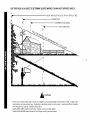
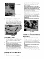
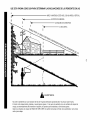
USE THIS PAGE AS A GUIDE TO DETERMINE
SLOPES
WHERE
YOU MAY NOT OPERATE
SAFELY.
I
I
I
B
r.D
15 °
_
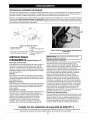
WARNING
Do not mow on inclines with a slope in excess of 15 degrees (a rise of approximately 2-1/2 feet every 10 feet). A riding mower
could overturn and cause serious injury. If operating a walk-behind mower on such a slope, it is extremely difficult to maintain
your footing and you could slip, resulting in serious injury.
Operate ZERO-TURN mowers across the face of slopes, never up and down slopes.
Operate WALK-BEHIND mowers across the face of slopes, never up and down slopes.
Congratulations on making a smart purchase. Your new
Craftsman® Professional product is designed and
manufactured for years of dependable operation. But like all
products, it may require repair from time to time. That's when
having a Repair Protection Agreement can save you money and
aggravation.
Here's what the Repair Protection Agreement* includes:
Expert service by our 10,000 professional repair
specialists
Once you purchase the Repair Protection Agreement, a simple
phone call is all that it takes for you to schedule service. You can
call anytime day or night, or schedule a service appointment
online.
The Repair Protection Agreement is a risk-free purchase. If you
cancel for any reason during the product warranty period, we will
provide a full refund. Or, a prorated refund anytime after the
product warranty period expires. Purchase your Repair
Protection Agreement today!
Unlimited service and no charge for parts and labor
on all covered repairs
Some limitations and exclusions apply. For prices and
additional information in the U.S.A. call 1-800-827-6655.
Product replacement up to $1500 if your covered
product cannot be fixed
*Coverage in Canada varies on some items. For full details
call Sears Canada at 1-800-361-6665.
Sears Installation
,_
Discount of 10% from regular price of service and
related installed parts not covered by the agreement;
also, 10% off regular price of preventive maintenance
check
Fast help by phone- we call it Rapid Resolution- phone
support from a Sears representative. Think of us as a
'_talking owner's manual."
Service
For Sears professional installation of home appliances, garage
door openers, water heaters, and other major home items, in the
U.S.A. or Canada call 1-800-4-MY-HOME®
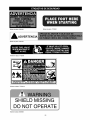
Part Number:
01001036
Part Number: 777122931
I_WARNING
Part Number:
Part Number:
01001036
777122930
Part Number: 777S30116
SHIELD MISSING
DO NOT OPERAT
Part Number: 00030635
Part
Number:
777122919
Part
Number:
777S33036
Part
Number:
777S30503
5TRANSPORT
|
Part Number:
01002166
Part Number: 777122929
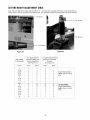
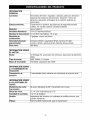
GENERAL
INFO.
Controls:
Engine ignition; throttle; choke; left and right operator presence
levers; left and right steering/brakes;
blade clutch; transmission
shift
Parking:
Transmission in 1st, neutral latches
chocked in front
Frame:
7 gauge steel
Front Caster Wheels:
Drive Wheels:
9 x 4.0-5 semi-pneumatic
13 x 6.50-6 pneumatic, 10-12 psi
Fuel Tank:
5 gallons, regular unleaded
Ground Speed:
(approximate)
l st=2.0mph,
5th=6.0mph,
Net Weight:
460 Ibs
ENGINE
released,
2nd=2.6mph,
3rd=3.1mph,
Reverse=2.2mph
rear wheels
4th=4.0mph,
INFO.
Engine:
Oil Type:
12.5 Briggs I/C, recoil start, dual element
SAE 15W40, 1.2 quart
Spark
759-3336,
plug:
air cleaner
0.030" gap
TRACTIONDrive:
DRIVE INFO. 15 speed forward with reverse assist
Traction
CUTTER
DECK INFO.
Cutter Deck; Drive:
Cutting Height:
No. of Blades
Spindle:
Pulleys:
36" fabricated steel; belt driven
2" to 4" in 1/4" increments
2 at 18" long
aluminum housing with taper roller bearings,
machined-cast
iron for drive
lO
greasable
IMPORTANT:This unit is shipped with oil in the engine.
After assembly, see OPERATION section of this
manual for fuel and engine oil details.
NOTE:
Reference to right and left hand side of the
mower is observed from the operating position.
This pedestrian controlled wide area mower has been
completely assembled at the factory.
LOOSEPARTSIN CARTON
The following items are packaged in a bag:
Operator's Manual and Engine Manual
TOOLSNEEDEDFORASSEMBLY
A tire Gauge
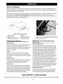
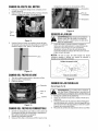
REMOVING
THEUNITFROMTHECRATE
1.
2.
Cut straps securing unit to pallet.
Remove any protective packaging and plastic tie
straps.
REMOVING
THECHUTESTRAP
1.
2.
Locate the chute strap which secures the discharge
chute in a vertical position.
Pull chute back towards the engine. While holding
the chute with one hand, cut the strap with the other
hand.
FINALADJUSTMENTS
Tire Pressure
The recommended operating rear tire pressure is 1012 psi. The caster wheels are semi-pneumatic and do
not require air pressure. Check the tire pressure
periodically and maintain equal pressure in both rear
tires at all times.
IMPORTANT: Refer to the tire sidewall for exact tire I
manufacturer;s recommended or maximum psi. Do not
overinflate. Uneven tire pressure could cause the
cutt ng deck to mow uneven y.
11
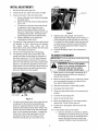
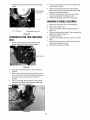
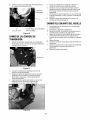
Know Your Mower
Read this operator's manual and safety rules before operating your Mower. Compare the illustrations below
with your equipment to familiarize yourself with the location of various controls, safety signs and adjustments.
Save this manual for future reference.
The operation of any lawn mower can result in foreign objects being thrown into the eyes, which can damage
your eye severely. Always wear safety glasses, while operating the mower or while performing any
adjustments or repairs on it. Check local regulations, hard hats and hearing protection may be required! Use
only approved accessories and attachments.
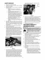
Figure
1 The Control
1. Ignition Switch
3. Engine Throttle
5. Right Steering Brake Lever
7. Operator Presence Lever
2.
4.
6.
8.
Panel
Choke
Blade Clutch lever
Neutral Latch Levers
Fuel Shutoff Valve
OPERATING
CONTROLS
(see
Figurel&
2)
Ignition Switch:
Located in the center of the control panel between the
handles. When the key is inserted and turned
clockwise 90 degrees, the engine can be started if the
transmission shift lever is in neutral and the blade
clutch is disengaged.
Choke:
Located on the control panel and is activated by
pulling upward. Activating the choke control closes
the choke plate on the carburetor and aids in starting
the engine.
Engine Throttle:
Located on the right side of the control panel between
the handles. Moving the throttle lever upward will
increase the engine speed from slow to fast.
Blade Clutch:
Located on the left handle below the control panel.
This is an over-center belt clutch. When the handle is
pushed forward it snaps to rest and forces the idler
pulley into the blade drive belt causing the blades to
rotate. Pull back the handle and the pressure on the
belt is relieved and the blades stop rotating.
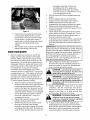
Figure 2 View Looking Under The Fuel Tank
9. Transmission Shift Lever
IMPORTANT:
I o avoid engine stalling, slowly I
engage the lever.
Steering Brake Levers:
I
There is a right-hand lever located beneath the outer
end of the right handle and a left-hand lever located
beneath the outer end of the left handle. Each lever
operates independently and when squeezed against
spring tension, lifts the idler pulley from applying
pressure to the traction drive belt on the right or left
side and applies the right or left side brake when
squeezed tightly. When the levers are released, the
mower will move ahead in a straight line if the engine
is running and the transmission is engaged in a
forward gear. Steering is accomplished by squeezing
the steering/brake lever on the side to which the turn
is to be made. A slight lever squeeze will allow belt
slippage and provide a gentle turn. Squeezing the
lever such that the neutral latch could be engaged will
provide a sharp turn, and continued lever squeezing
will apply the brake providing a pivot turn.
Neutral Latch Levers:
Pivoted inside each handle, there is a neutral latch
lever which works with each of the steering/brake
levers. When either of the steering/brake levers is
Meets ANSI B71.4 safety standards
Craftsman pedestrian controlled wide area mower conform to the safety standard of the American National Standards Institute (ANSI).
12
squeezed
anditsneutrallatchleverpushedforward
andengagedintheneutrallockposition,the
steering/brake
leveris heldina positionwherethe
idlerpulleyis notapplyingpressure
tothetraction
drivebeltandthebrakeis notengaged.
must be in the Neutral position in order to start the
engine. Never attempt to mow in Fifth Gear. Fifth
Gear should be used for transport only.
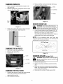
Transmission
Shift Lever
neutral lock
position
Figure 5
IMPORTANT: DO NOT shift the transmission from
one forward gear to another while unit is moving.
Stop forward travel, shift gear, then resume
movement.
Figure 3
IMPORTANT: The neutral latch levers must be
I
engaged in the neutral lock position before starting I
the engine. They should not be loose so that they will
stay n the un ocked post on un ess moved.
Operator Presence Levers:
Located above the outer ends of the right and left
handles, at least one of these operator presence
levers must be held down on the handles against
spring pressure in order to shift the transmission shift
lever into gear or engage the blade clutch. Releasing
the operator presence levers with either the
transmission shift lever in gear or the blade clutch
engaged will shut off the engine.
IMPORTANT: One or both operator presence levers
must be depressed when n gear or mow ng.
Fuel Shutoff Valve:
Located on top of the fuel tank is the fuel shutoff
valve. The handle turns 90 degrees. When the
handle is in a horizontal position, it will shut off the
flow of fuel to the engine. When it is turned to a
vertical position, it will open and allow fuel to flow to
the engine. Anytime the mower is being trailered or, if
the mower will not be in use for 30 minutes or more,
close the fuel shutoff valve to prevent flooding the
engine.
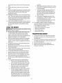
GASANDOILFILL-UP
Oil
IMPORTANT: The mower is shipped with motor oil in
the engine; however, you MUST check the oil level
before operating. Oil should be changed once after
the first five hours of operation and every 40 hours of
operation thereafter. Use the grade of engine oil
specified in the Maintenance section.
•
•
Remove oil fill dipstick from the oil fill tube.
Check that the level of oil is up to the FULL mark
on the dipstick. If needed, pour oil slowly into the
oil fill tube until a FULL oil level is achieved.
•
Replace oil fill dipstick and tighten.
Gasoline
•
•
•
Fuel Shutoff
Valve
•
Remove fuel cap from the fuel tank.
Make sure the container from which you will pour
the gasoline is clean and free from rust or foreign
particles. Never use gasoline that may be stale
from long periods of storage in its container.
Gasoline that has been sitting for any period
longer than four weeks should be considered
stale.
Fill fuel tank with clean, fresh, unleaded regular
gasoline (87 ROM) only no more than one inch
below bottom of filler neck to provide space for
fuel expansion. Replace fuel cap.
To avoid engine problems, the fuel system should
be emptied before storage for 30 days or longer.
Drain the fuel by shutting off the fuel valve and
running the engine until it stops. Use fresh fuel
next season. See STORAGE section for
additional information.
Figure 4
Transmission
Shift Lever:
Located under the control panel. The lever has
seven positions moving from the left to the right:
Reverse Gear, Neutral, First Gear, Second Gear,
Third Gear, Fourth Gear and Fifth Gear. The lever
_lb
•
13
I
system indoors, or operate or store near an
DANGER: Never refuel or drain the fuel I
open flame, spark, or ignition source.
Check the fuel level periodically to avoid running
out of gasoline while operating the mower.
INITIALADJUSTMENTS
1.
Disconnect the spark plug wire.
2.
3.
Check that all nuts, bolts and screws are tight.
Check the tension of the deck drive belts:
a.
Remove the deck cover shield and engage
the blade clutch.
b.
Make surethe belts clearthe belt guides by
1/8" to 1/4".
The tension of the deck drive belts should
c.
,
needed.
Hair Pin
be adjusted so that a ten-pound pull
between two pulleys deflects each belt
about 1/2" (See Figure 19 page 19). Do not
overtighten these belts. The blade clutch
should engage with only moderate force.
d. Replace the deck cover shield and
disengage the blade clutch.
The tension of the transmission drive belt should
Figure 7
8.
be adjusted so that a five-pound pull between
the engine traction drive pulley and the
transmission drive pulley deflects the belt about
3/16". (See Figure 20 page 20)
,
6.
9.
The two drive wheel belts are self-adjusting.
The steering control rods on each side of the
handle assembly should initially be adjusted so
that there is about a 1/4" to 3/8" space between
the rod and the bottom of the slot in the neutral
Adjusting the cutting height: The mower is
shipped with the cutting height set at 3 inches _+1/
4 inch depending on the air pressure in the tires.
To change the cutting height, blade spacers and/
or caster spacers must be moved according to
the cutting height adjustment table. (Figure 24
and 25, page 22)
Lubricate all fittings listed in the maintenance
section.
TOSTARTTHEMOWER
IMPORTANT: First time operators should refer to the
procedure stated on page 5.
latch lever with the latch in the drive position (See
Figure 6.) To make this adjustment, remove the
large hairpin from the swivel joint at the bottom of
each steering control rod and thread the swivel
joint up or down the rod as needed.
indoors or in a poorly ventilated area.
Engine
exhaustNever
contains
carbon
ARNING:
run the
engine
monoxide, a deadly, odorless gas.
[_
1.
Make certain you thoroughly understand all of
the safety precautions before you attempt to
operate this machine.
2.
Move the mower outdoors to a "test area" where
you can operate the mower for about half an
hour without being disturbed.
3.
Shift the transmision to neutral (N) position.
4.
Disengage the blade clutch.
5.
Place the neutral latch levers in the neutral lock
position.
Figure 6
,
The brake rods (above each drive wheel) should
be adjusted so that when the steering/brake
levers are squeezed and the mower is pulled
backward, the brakes lock the drive wheels. The
machine should roll freely when the neutral latch
lever is in the neutral lock position. To adjust the
brake rods, remove the large hairpin from the
swivel joint at the top of each brake rod and
thread the swivel joint up or down the rod as
6.
Connect the spark plug wire.
7.
Open the fuel shutoff valve.
8.
Move the throttle lever to a mid range position
and pull the "Choke" all the way out.
9.
Put the key in the ignition switch and turn the
switch on.
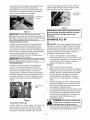
10. To start engine using recoil starter:
a.
14
Stand on left side (as viewed from behind
handlebars) of machine. Be sure your feet
are safely away from the underside of the
mower deck and all mower controls are
released. Stabilize mower by placing foot
as indicated below in Figure 8.
2.
3.
4.
5.
Figure 8
b.
c.
6.
Grasp starter rope handle and pull slowly
until rope pulls slightly harder. Let rope
rewind slowly. Then pull rope with a rapid,
full arm stroke. Let rope return slowly. If
engine fails to start after three pulls, repeat
instructions (try setting throttle at fast
setting).
When engine starts, operate in fast throttle
setting (move choke control to off).
7.
IMPORTANT: Squeezing the control levers from the
released position to the Neutral lock position releases
traction-drive belt tension. Additional squeezing of
these levers applies the service brakes. Applying the
left brake will create a counter clockwise pivot or uturn and applying the right brake will create a
clockwise pivot or u-turn. Applying both brakes will
stop the machine without turning.
KNOWYOURMOWER
,
After the engine has warmed up, shut off the
ignition and check the operation of the safety
switches. Make certain that the engine will not
start unless the ignition switch is turned on, the
transmission is in neutral and the blade clutch is
disengaged. Place the neutral latch levers in the
neutral lock position. If the engine will start with
the transmission in any gear (not neutral),
immediately shut off the engine and contact
customer service at 1-800-659-5917 or log on to
managemyhome.com. If the engine will start with
the blade clutch engaged, immediately shut off
the engine and contact customer service at 1800-659-5917 or log on to managemyhome.com.
To check operator presence controls:
a.
Start the engine and hold the left operator
presence control lever down against the left
handle and move the transmission shift
lever into first gear. Now take your hand off
the operator presence control lever and the
engine should die. If it does not, immediately
shut off the engine and contact customer
service at 1-800-659-5917 or log on to
managemyhome.com.
b. Repeat this procedure using the right
operator presence control lever.
c. Shift the transmission into neutral, restart
the engine, hold one of the operator
presence controls down against the handle
and engage the blade clutch. Now take your
hand off of the operator presence lever and
the engine should die. If it does not,
immediately shut off the engine and
disengage the blade clutch and contact
customer service at 1-800-659-5917 or log
on to managemyhome.com.
With the neutral latch levers engaged restart the
engine.
Push the blade clutch lever forward until it
engages and the cutter blades start rotating.
Shift the transmission into first gear. (It is
suggested that you practice mowing in first gear.)
Squeeze both steering/brake levers with both
hands and release the neutral latch levers from the
neutral lock position.
Slowly release the steering/brake levers and the
mower will move ahead in a straight line. To turn
the mower, squeeze the steering/brake lever on
the side to which you want to turn.
To stop the mower's forward motion, squeeze both
steering/brake levers until the mower stops and
place the neutral latch levers into the neutral lock
position.
8.
Before shifting into reverse gear, the mower's
forward motion must be completely stopped. For
maximum traction in reverse, the steering/brake
levers should be pushed downward.
and during Reverse operation. Stop the mower
DANGER:
Look behind the mower before
blades before operating in Reverse.
I_,
9.
and to prevent damage to the transmission,
the mower must be completely stopped before
attempting
ARNING:
to shift
Toavoid
from forward
possibletobodily
reverse
injury
or
reverse to forward.
Practice operating the mower and as you gain
confidence, shift the transmission from first to
second and mow for a while and then shift from
second to third. Mow for at least one-half hour
and then return the mower to the shop.
I
_lb
shifted-on-the-go as transmission damage
could
occur, causing
the machine
to not
suddenly
WARNING:
The machine
should
be
I
stop Stop the mach ne, then sh ft.
10. To stop and shut off the mower, squeeze both
steering/brake levers and place the neutral latch
levers into the neutral lock position, disengage the
blade clutch, shift the transmission into neutral,
turn off the ignition to stop the engine, close the
15
machine.
fuel shutoff valve and disconnect the spark plug
wire.
11. Check that all nuts, bolts and screws are still
tight.
12. Check, and adjust if necessary, the tension of the
deck drive belts and the transmission drive belt
as described in items 3 and 4 of the Initial
Adjustment section.
13. Readjust the steering control rods and the brake
rods. They may require frequent adjustment until
the belts and brake bands have properly seated.
These adjustments are described in items 6 and
7 of the Initial Adjustment section.
14. After the first full day of mowing, all nuts, bolt and
screws should be rechecked for proper tightness
and the belts should be rechecked for proper
tension.
5.
Slowly release the steering control levers and the
mower should go straight ahead.
To operate in Reverse, look behind and down
before backing up to be sure the path is clear.
Be aware of the mower discharge and do not
point it at anyone, or onto sidewalks and streets.
Use care when approaching blind corners,
shrubs, trees or other objects that could obstruct
vision.
6.
7.
8.
9.
g.
If the grass is repeatedly mowed in the
same direction, it will be "trained" so that
the Striped appearance is more
pronounced and longer lasting. Grooving
of the turf from the tires will occur.
TRANSPORTING
MOWER
1.
With the neutral latches locked and the operator
presence levers depressed, select a mowing
speed. (a slower speed is suggested during first
time use.)
Engage the mower by pushing the blade clutch
lever forward until it locks.
Squeeze the steering control levers and release
the neutral latches.
To prevent rutting or grooving of the turf,
change the direction that the strips are
mowed by approximately 45 degrees the
next and each subsequent time that the
area is mowed.
• shut off the engine.
• apply wheel chocks.
I
4.
f.
• place the transmission in neutral.
• latch the neutral locks.
MPORTANT:
First
should refer to the I
rocedure stated
ontime
pageoperators
5.
1. Be sure area is clear of rocks, sticks, toys, wire,
or other objects that could be thrown by the
mower. Survey the entire area to be mowed.
Make sure that the accessories and attachments
would be suitable for use on the terrain.
3.
When approaching the other end of a strip,
slow down or stop before turning. A U-turn
is recommended.
10. For empting material collection systems or for
any other operation involving the mower deck,
before leaving the operator station:
• shut off the mower deck.
USINGTHEMOWER
2.
e.
2.
3.
4.
5.
To mow grass and produce a striped pattern:
a. Pick a point on the opposite side of the
area to be mowed (post, tree, shrub, etc).
b. If on a hillside, start at the bottom so that
the turns are uphill rather than downhill.
c. Align the mower so as to head directly
toward the object on the far side.
d. Slowly increase the speed of the machine
to match cutting conditions, terrain, and
operator familiarity with the controls and
keep the machine headed directly toward
the alignment object. Do not go fast as to
reduce cut quality or to be uncomfortable in
controlling the speed and direction of the
16
If ramps are used, be sure they are secured to
the trailer, truck bed, etc. and are designed for
the application.
The mower should be pushed or pulled onto or off
the trailer, truck bed, etc., never try to drive it on.
Turn the fuel valve off.
Secure mower with chocks, straps, etc.
Make sure accessories and attachments are
secured or removed.
GENERAL
RECOMMENDATIONS
Transmission-Jackshaft
Couplers- There are
two grease positions. See Figure 11 item H
people
operate or
service
the mower.
WARNING:
Never
let children
or untrained
•
•
•
•
Always observe safety rules when performing any
type of maintenance on the mower.
The warranty on this lawn mower does not cover
items that have been subjected to operator abuse
or negligence. To receive full value from the
warranty, operator must maintain the equipment as
instructed in this manual.
Changing of engine-governed speed will void
engine warranty.
Periodically check all fasteners and make sure they
are tight.
Figure 9
disconnect and ground the spark plug wire
J&
ARNING: Always stop the engine and I
before performing any maintenance or
adjustments.
Engine Oil: Use Shell Rimula 15W40 oil or any 10W30
or 15W40 oil rated SJ or higher.
Spindle Lubricant: Use only Shell Alvania RL 2
grease. This grease is an amber-colored grease
designed for high speed bearing applications. It has a
base oil viscosity that reduces running losses, has
been formulated for low noise, has excellent corrosion
_rotection, and has excellent bearing lubrication.
3eneral Purpose Lubrication: Use any NLGI grade 2
multi-purpose grease. Shell Albida EP2 is recommended. Shell Albida EP 2 is a red-colored multi-purpose grease designed for heavy-duty bearing
_pplications. It has high base oil viscosity for mechani;al stability, has been formulated for high load, lowspeed applications, and has excellent lubrication and
;orrosion protection.
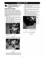
Figure 10
LUBRICATION
(see
Figures9,10 & 11)
Daily
•
Cutter Blade Spindle Bearings- There are two
grease positions. See Figure 9 item A.
•
Caster Wheel Bearing- There are two grease
positions. See Figure 9 item B.
•
Caster Wheel Pivot Shafts- There are two grease
positions. See Figure 9 item C.
•
Deck Idler Pulley Pivot Arms- There is one
grease position. See Figure 9 item D.
Every 40 Hours
•
•
•
H
G
View looking from the front
Drive Wheel Bearings- There are two grease
positions. See Figure 10 item E.
Brake Lever Pivots- There are two grease
positions. See Figure 10 item F.
Blade Clutch Bellcrank Pivot- There is one
grease position. See Figure 11 item G.
Figure 11
ENGINEMAINTENANCE
For detailed maintenance instructions for the engine
on your mower, see the separate engine manual
packed with your mower.
17
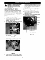
CHANGING
ENGINEOIL
,
1.
Place a container underneath the mower on the
2.
right hand side.
Remove oil drain plug, and replace when oil stops
draining. (See Figure 12)
Remove old filter and insert new filter into hoses,
and move clamps near filter.
Clamp
Fuel Filter
Clamp
Drain
Plug
Figure 15
SERVICESPARKPLUG
Figure 12
,
adjustment to the unit without first stopping
WARNING:
Do not at any time
engine and disconnecting
sparkmake
plug any
wire.
Refill oil through the fill tube to the level indicated
as "full" on the dipstick. (See Figure 13)
•
Clean the spark plug and reset the gap to.030" at
least once a season or every 50 hours of operation.
See Figure 16. Spark plug replacement is
recommended at the start of each season. Refer to
engine parts list for correct spark plug type.
Full
NOTE:
Do not sandblast spark plug. Spark plug
should be cleaned by scraping or wire brushing and
washing with a commercial solvent.
.030" Ga
Figure 13
CHANGING
THEAIRFILTER
1.
2.
3.
Plug
Pull cover to open and expose filter.
Remove and replace filter.
Close cover.
Figure 16
CHANGING
A BLADE€see
Figure17
&18)
Latch
I
gloves or wrap blades to protect yourself from
WARNING:
Mower blades are sharp. Wear I
the sharp edges.
Air Filter
cover
1.
Remove the deck cover.
2.
Tip the mower back and block up the front of the
deck.
Place one wrench on the hex head bolt under the
blade. Use a second wrench to remove the Iocknut
3.
Figure 14
4.
CHANGING
THEFUELFILTER
1.
2.
Squeeze the clamps on either side of the fuel filter
hose, and move them away from the filter
approximately one inch.
Pull the hoses off the filter.
18
on top of the spindle pulley.
Remember the number of blade spacers both
above and below the spindle.
2.
3.
1/4" Spacer
4.
5.
6.
7.
1/4" Spacers
Figure 17
,
6.
Remove the long (9-1/2") blade bolt, the flat
washer, the blade and the blade spacers.
To replace the blade, reverse the above
procedure. Be careful to replace the blade
spacers correctly above and below the spindle.
This is not a timed blade system and since blade
overlap is provided, orientation is not important.
8.
Remove the deck cover. (This requires a 9/16"
wrench)
Remove the cap screw which serves as a belt
guide and is mounted in the idler pulley arm.
(Item J, Figure 19.)
Slip the long blade drive belt off of the pulleys.
Place a new long blade drive belt through the belt
guide and loop it around the engine pulley and
then around the two deck pulleys. The belt's back
side should ride on the idler pulley.
Replace the cap screw, lock washer and nut in
the idler pulley arm.
The idler pulleys should be adjusted so that when
the blade clutch is engaged, a ten-pound pull
between two pulleys deflects either belt about 1/
2" (See Figure 18.) Do not overtighten these
belts. The blade clutch should engage with only
moderate force.
Replace the deck cover, and secure with 9/16"
nut.
1/2" deflection
Figure 19
CHANGING
THETRANSMISSION
DRIVE
Figure 18
BELT:(SeeFigure20)
SHARPENING
A BLADE
,
,
3.
To sharpen a blade, clamp the blade in a vise
and, using a flat mill file, carefully file the cutting
surface on each end of the blade to a sharp
edge.
Make sure the blade clutch is disengaged.
2.
Working under the engine deck, take the long
blade drive belt off of the engine pulley.
Loosen the Iocknut (item I, Figure 20) holding the
transmission drive belt idler pulley in place and
slide the pulley away from the transmission drive
belt.
Remove the old belt and mount a new belt onto
the pulleys.
Slide the idler pulley back onto the belt and
tighten the Iocknut holding it in place. The idler
pulley should be adjusted so that a five-pound
pull on the belt between the engine pulley and the
transmission pulley deflects the belt about 3/16".
3.
Blades with severe nicks or dents that cannot be
removed by filing should be replaced.
It is important that each cutting blade edge be
ground equally to maintain proper blade balance.
A poorly balanced blade will cause excessive
vibration and may cause damage to the mower
and result in personal injury. The blade can be
tested by balancing it on a round shaft
screwdriver. Grind metal from the heavy side until
it balances evenly.
4.
5.
CHANGING
THEBLADEDRIVEBELTS
(SeeFigurelg)
1.
1.
Make sure the blade clutch is disengaged.
19
,
Replace the long blade drive belt on the engine
pulley.
5.
Prop up the side of the mower and slip the belt
over the drive wheel.
6.
Slip the new traction drive belt over the drive
wheel and loop it over the jackshaft pulley while
lifting up on the idler bracket.
Insert the swivel joints in the holes in the idler
bracket and replace the hairpin cotters.
Replace the belt guards and the hex screws.
. transmission
drive belt
7.
8.
CHANGING
A SPINDLEASSEMBLY
3/16" deflection
long blade drive belt
1.
2.
Make sure the blade clutch is disengaged.
Remove the deck cover.
3.
Remove the blade. (See changing a blade on
page 18.)
Remove the blade drive belts. (See changing the
blade drive belts on page 19.)
Remove the pulley.
Tip the mower back and block up the front of the
deck.
4.
Figure 20
5.
6.
CHANGING
EITHERTRACTIONDRIVE
BELT:
1.
7.
Remove the hex screws which hold the belt
guards in place. Remove the belt guards.
8.
Screws
Figure 21
2.
3.
4.
Place the neutral latch lever in the neutral lock
position.
Remove the hairpin cotters from the two swivel
joints which are inserted through the idler bracket
and remove the swivel joints from the idler
bracket.
Lift up on the idler bracket with one hand while
removing the belt from the jackshaft pulley with
the other hand. (See Figure 22.)
Figure 22
20
Remove the four bolts and Iocknuts holding the
spindle assembly to the deck.
Remove the spindle assembly.
WARNING: Do not at any time make any
adjustment to the unit without first
stopping engine and disconnecting
spark plug wire.
6.
ADJUSTINGTHELITE-TOUCH
7.
Three holes in the belt guard allow you to reposition
the hex cap screw to adjust the brake lever. The top
hole (lite tension), the middle hole (medium tension)
and the lower hole (hard tension). The unit is shipped
with the hex screw in the top hole. SEE FIGURE 25
BELOW FOR REFERENCE. To adjust the bolt do the
following:
1.
2.
3.
8.
9.
are having difficulty removing the bolt, continue to
loosen the lower nut on the inner belt guard (BUT
DO NOT REMOVE). Remove the bolt and nut.
(See Figure 25)
Reposition the bolt and nut into the middle or
lower hole and retighten the nut. (See Figure 25)
Using a spring puller, reattach the spring to the
hex cap screw. (See Figure 23)
Reposition the inner belt guard, reinstall the
upper nut, and retighten the lower and upper
nuts. (See Figure 25)
Reposition the outer belt guard, reinstall the hex
screws. (See Figure 21 page 20)
Remove the hex screws retaining the outer belt
guard. (See Figure 21 page 20)
Remove the upper nut retaining the inner belt
guard, and loosen the lower nut (DO NOT
REMOVE). (See Figure 25)
With a spring puller, pull the spring and detach it
from the hex cap screw. (See Figure 23)
Upper Nut
Medium
Inner Belt Guard
Loosen the lower nut (DO NOT REMOVE)
Hex Cap Screw
Figure 25
Spring
Figure 23
,
Remove the lock nut from the lite touch hole in
the inner belt guard. (See Figure 24)
Lock Nut
Figure 24
,
Pull the inner belt guard away from the unit. This
will give clearance to remove the bolt. Note: If you
21
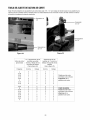
CUTTINGHEIGHTADJUSTMENTTABLE
Note: The front edge of the cutting deck should be 1/8" - 1/4" below the rear edge of the deck so that the blades are
cutting grass in only the front half of their circular path. This decreases friction and reduces the drive power required.
1/4" Spacer
1/2" Spacer
1/2" Spacers
1/4" Spacers
Figure 24
Approximate
Cutting Height
Figure 25
1/4": Blade Spacers
Above and Below The
Spindle Assemblies
(See Figure 24)
1/2" Caster Spacers Above
and Below The Caster
Bracket
(See Figure 25)
Inches
Above
Below
Above
Below
2
2-1/8
2-3/8
2-1/2
2-3/4
3
3-1/4
3-1/2
0
1
2
1
2
3
4
5
5
4
3
4
3
2
1
0
3
3
3
2
2
2
2
2
1
1
1
2
2
2
2
2
2-3/4
3
3-1/4
3-1/2
3-3/4
3-1/4
3-1/2
3-3/4
4
0
1
2
3
4
0
1
2
3
5
4
3
2
1
5
4
3
2
2
2
2
2
2
1
1
1
1
2
2
2
2
2
3
3
3
3
22
Engine Deck bolted to
upper holes on cutting
deck.
AS DELIVERED
Engine Deck bolted to
lower holes on cutting
deck.
MAINTENANCE
SCHEDULE
WARNING
Before performing any type of maintenance/service,
disengage all controls and stop the engine. Wait until
all moving parts have come to a complete stop.
Disconnect spark plug wire and ground it against the
engine to prevent unintended starting. Always wear
safety glasses during operation or while performing
any adjustments or repairs.
Item
Interval
Each Use
1.
2.
3.
4.
5.
6.
7.
1st 5 hours
40 hours
Mower Blades
Loose or missing hardware
Belts
Engine oil level
Fuel level
Controls
Cutter Blade Spindle Bearings
1. Engine oil
1.
2.
3.
4.
5.
Before Storage
Follow the maintenance
service guidelines only.
completed maintenance
Center or to schedule
1-800-4-MY-HOME®.
Engine oil
Air cleaner
Mower blades
Spark plug
Follow lubrication chart
• Fuel System
schedule given below. This chart describes
Use the Service Log column to keep track of
tasks. To locate the nearest Sears Service
service, simply contact Sears at
Service
1. As required
2. Tighten or replace
3. Check
4. Check
5. Check
6. Check for proper orientation
7. Lubricate
1. Change
1.
2.
3.
4.
5.
Change
Clean or replace
Sharpen and balance
Clean, replace, re-gap
Lubricate
1. Run engine until it stops from
lack of fuel or add a gasoline
additive to the gas in the tank.
23
Service Log
WARNING
Never store lawn mower with fuel in tank indoors or in
poorly ventilated areas where fuel fumes may reach
an open flame, spark, or pilot light as on a furnace,
water heater, clothes dryer, or gas appliance. Never
refuel or drain the fuel system indoors.
PREPARING
THE ENGINE
PREPARING
For engines stored over 30 days:
1. To prevent gum from forming in fuel system or on
carburetor parts, turn off the fuel valve, run the
engine until it stops from lack of fuel or add a gasoline additive to the gas in the tank. If you use a gas
additive, run the engine for several minutes to circulate the additive through the carburetor, after which
the engine and fuel can be stored up to six months.
2. While engine is still warm, change the oil.
3. Remove spark plug and pour approximately 1 oz.
(30 ml) of clean engine oil into the cylinder. Pull the
recoil starter several times to distribute the oil, and
reinstall the spark plug.
4. Clean engine of surface debris.
•
•
•
PART NO.
DESCRIPTION
33317
Bagger Grass Collector
33318
Mulch Kit
24
THE LAWN MOWER
When storing the mower in an unventilated or metal
storage shed, care should be taken to rustproof the
non-painted surfaces. Using a light oil or silicone,
coat the equipment, especially any springs, bearings, and cables.
Remove all dirt from exterior of engine and equipment.
Store equipment in a clean, dry area. Do not store
in an area where equipment is present that may use
a pilot light or has a component that can create a
spark, or open flame.
WARNING
NEED MORE HELP?
Y_
Before performing any type of maintenance/service, disengage all
controls and stop the engine. Wait until all moving parts have come
to a complete stop.
Disconnect spark plug wire and ground it against the engine to prevent unintended starting. Always wear safety glasses during operation or while performing any adjustments or repairs.
[ _h/d the _
we_ _t
_ _oe
o F_d tMs and a_.[ you_ otl_e_ product
o_ _a_agemyhomeocom
_ _o_ f_ee_
manuals online.
- Get a_swers from our team of hol_le experts,
o Get a personalized
maintenance
plan for your home,
, F;I_ il_folmat_or_ and tools to help w_th home project,
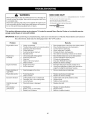
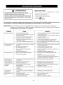
This section addresses minor service issues. To locate the nearest Sears Service Center or to schedule service,
simply contact Sears at 1-800-4-MY-HOME®.
IMPORTANT:
Before performing any troubleshooting, make sure: transmission is in Neutral, Neutral latches are locked on
the control levers, blade clutch is disengaged and in the "OFF" position.
Problem
Cause
Remedy
Engine fails to start
1.
2.
3.
4.
5.
6.
Choke not activated
Throttle/choke control not in correct position
Spark plug wire disconnected
Faulty spark plug
Fuel tank empty or stale fuel
Blocked fuel line
1.
2.
3.
4.
5.
6.
Place throttle/choke control lever into choke position..
Place throttle/choke lever into fast position.
Connect wires to spark plug.
Clean, adjust gap, or replace.
Fill tank with clean, fresh gasoline.
Have fuel line cleaned by a Sears service dealer.
Engine runs
erratically
1.
2.
3.
4.
5.
Unit running with choke applied
Spark plug wire loose
Stale fuel.
Water or dirt in fuel system.
Dirty air cleaner
1.
2.
3.
4.
5.
Move throttle/choke lever out of choke position.
Connect and tighten spark plug wire.
Fill tank with fresh gasoline.
Drain fuel. Refill with fresh fuel.
Replace air cleaner cartridge.
Engine overheats
1.
2.
Engine oil level low
Air flow restricted
1.
2.
Fill engine with proper amount and type of oil.
Clean grass clippings and debris from around the
engine's cooling fins and blower housing.
Engine hesitates at
high RPM's
1.
Spark plug gap set too close
1.
Remove spark plug and adjust gap
Engine idles poorly
1.
2.
Fouled spark plug
Dirty air cleaner
1.
2.
Replace spark plug and adjust gap.
Replace air cleaner cartridge.
Excessive vibration
1.
2.
3.
Cutting blades loose or unbalanced
Damaged, dull, or bent cutting blade
Loose hardware
1.
2.
3.
Tighten blade and spindle. Balance blade.
Replace blade.
Tighten all nuts and bolts.
Unit fails to propel
itself
1.
Drive belts loose or damaged
1.
Replace drive belt.
Poor mowing
performance
1.
2.
3.
Dull blade(s)
Broken, loose, or worn belt(s)
Blade(s) out of balance
1.
2.
3.
Sharpen or replace blade(s).
Replace belt(s).
Balance or replace blade(s).
25
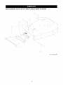
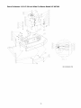
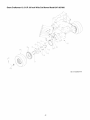
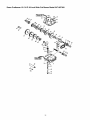
Sears Craftsman
12.5 H.P. 36-inch Wide Cut Mower Model 247.887360
\
•
GD: 01005995-P04
26
Sears Craftsman
12.5 H.P. 36-inch Wide Cut Mower Model 247.887360
Ref. No.
Part No.
1.
712-04065
Hex Nut, 3/8-16, Flange Lock
2
2.
01000643
Carriage Bolt 3/8-16 x 1.00
2
3.
01003253
1
4.
01003254
Torsion Spring
Chute Deflector Rod
5.
01006693
Deflector Chute
1
6.
01009884
Deflector Chute Bracket
1
Part Description
Qty.
1
NOTE: For painted parts, please refer to the list of color codes below. Please add the applicable color code, wherever needed,
to the part number to order a replacement part. For instance, if a part, numbered 0100-xxxx, is painted Sears yellow, the part
number to order would be 0100-xxxx-04028.
Sears Yellow:
04028
Powder Black:
0637
27
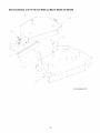
Sears Craftsman
12.5 H.P. 36-inch Wide Cut Mower Model 247.887360
GD: 02005528-T03
28
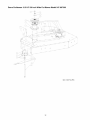
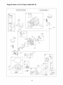
Sears Craftsman
12.5 H.P. 36-inch Wide Cut Mower Model 247.887360
Ref. No.
Part No.
Part Description
Qty.
1.
00012158
Flat Washer, 3/8 Zinc
1
2.
00014608
Lock Nut, Nylon Insert, 10-32
8
3.
4.
00017778
00021951
Phillips Head Screw, #10-32 x 1/2
Rubber Hood Latch
8
2
5.
712-04065
Hex Nut, 3/8-16, Flange Lock
1
Self Tapping Screw, 1/4-20 x 0.75
Trail Shield
3
Deck Cover, 36
Trailshield Plate
1
6.
01000629
7.
02005520
8.
02005533
9.
02005636
1
1
NOTE: For painted parts, please refer to the list of color codes below. Please add the applicable color code, wherever needed,
to the part number to order a replacement part. For instance, if a part, numbered 0100-xxxx, is painted Sears yellow, the part
number to order would be 0100-xxxx-04028.
Sears Yellow:
04028
Powder Black:
0637
29
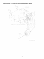
Sears Craftsman
12.5 H.P. 36-inch Wide Cut Mower Model 247.887360
c4_
\
\
\
/
L
/
/
/
/
/
DETA
] •
,A,
GD: 02005529-T03
3O
Sears Craftsman
12.5 H.P. 36-inch Wide Cut Mower Model 247.887360
Ref. No.
Part No.
1.
00012158
Flat Washer, 3/8 Zinc
2.
00012169
Flat Washer, 5/16 Zinc
1
3.
00012173
7
4.
00012402
Lock Nut, Nylon Insert, 3/8-16
Shim Washer
5.
00013406
1
6.
00013433
7.
00014439
Hex Cap Screw, 5/16-18 x .75
Hex Nut, 5/16-18
Shoulder Bolt
8.
00014459
Eye Bolt, Right Hand
1
9.
00018468
Cap, Black Vinyl
4
10.
00019271
00019554
Eye Bolt, Left Hand
Turnbuckle
1
11.
12.
00021956
Hair Pin, 3/8"-1/2"
4
13.
00021958
Grease Fitting, 45 ° , 1/4-28
1
14.
00021961
E-Ring, Retainer
1
15.
00021977
Idler Deck Take-up
1
16.
00062715
Turnbuckle, Sleeve
2
17.
01000160
Spacer, Belt Guide
5
18.
01000517
Carriage Bolt, 1/2-13 x 1-1/4
6
19.
01000635
Nut, Hex Flange Lock, 5/16-18
1
20.
01000644
4
21.
01000826
Carriage Bolt, 3/8-16 x 4.5
Deck 36"
22.
01000872
Washer, 1.25 x .411 x .100
1
23.
01001371
Hex Cap Screw, 3/8-16 x 2.75
2
24.
01002010
Carriage Bolt, 3/8-16 x 1-1/4
2
25.
01002011
2
26.
01002103
Carriage Bolt, 3/8-16 x 1-1/2
Rod Clutch Link
27.
00063043
Idler Base
1
28.
01003153
Clutch Link
1
29.
01005061
Deck Stiffener
1
30.
01009906
Carriage Bolt, 3/8-16 x 5.00
1
31.
01010119
6
32.
02000320
Nut, Flange Lock, 1/2-13
Chute Baffle
33.
00021895
Idler Arm
1
Part Description
Qty.
5
1
1
1
1
1
1
1
00021990
Bearing
2
34.
02002426
Bar Weight
1
35.
712-04065
36.
01008225
Flange Lock Hex Nut, 3/8-16
Push Retainer
2
5
NOTE: For painted parts, please refer to the list of color codes below. Please add the applicable color code, wherever needed,
to the part number to order a replacement part. For instance, if a part, numbered 0100-xxxx, is painted Sears Yellow, the part
number to order would be 0100-xxxx-04028.
Sears Yellow:
04028
Powder Black:
0637
31
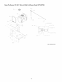
Sears Craftsman
12.5 H.p. 36-inch Wide Cut Mower Model 247.887360
GD: 01007704_P05
32
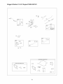
Sears Craftsman
12.5 H.P. 36-inch Wide Cut Mower Model 247.887360
Ref. No.
Part No.
1.
2.
3.
4.
5.
6.
7.
00010980
00011807
00021924
712-04065
00050125
00050441
01007491
01007642
01007499
01007577
01007591
01007595
8,
9.
10.
11.
Part Description
Hex Cap Screw, 3/8-16 x 1-1/2
Hex Nut, 5/8-11
Blade Spacer, 5/8 ID, 1/4 Thick
Hex Nut Flange Lock, 3/8-16
18" Rotary Blade
V-Belt
Spindle Assembly
Grease Fitting, 1/4-28 x 1.609
Deck Pulley
Blade Spacer, .630 x 1.500 x 1.850
Hex Cap Screw, 5/8-11 x 9
Flat Washer, .656 ID x 1.313 OD
Qty.
8
2
10
10
2
1
1
1
1
2
1
1
NOTE: For painted parts, please refer to the list of color codes below. Please add the applicable color code, wherever needed,
to the part number to order a replacement part. For instance, if a part, numbered 0100-xxxx, is painted Sears Yellow, the part
number to order would be 0100-xxxx-04028.
Sears Yellow:
04028
Powder Black:
0637
33
Sears Craftsman
12.5 H.P. 36-inch Wide Cut Mower Model 247.887360
\
i[/•
/
//
/
/
GD: 01005984-P09
34
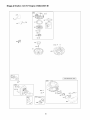
Sears Craftsman
12.5 H.P. 36-inch Wide Cut Mower Model 247.887360
Ref. No.
Part No.
1.
2.
3.
4.
5.
6.
7.
8.
9.
10.
00012428
00012675
00014528
00021925
712-04065
00060078
01000643
01000746
01001051
01006718
00064164
02000192
11.
Part Description
Lock Nut, Nylon Insert, 1/2-13
Hex Cap Screw, 1/2-20, 5.50
Spacer Wheel
Spacer, Caster
Hex Nut Flange Lock, 3/8-16
Grease Fitting, 1/4-28 x 3/16
Carriage Bolt, 3/8-16 x 1
Klik Pin, 1.75
Caster Yoke Assembly, Weldment
Caster Bracket Assembly
Caster Bushing
Wheel Assembly, 9.0 x 3.50-4
Qty.
2
2
2
8
8
2
8
2
1
1
4
1
NOTE: For painted parts, please refer to the list of color codes below. Please add the applicable color code, wherever needed,
to the part number to order a replacement part. For instance, if a part, numbered 0100-xxxx, is painted Sears Yellow, the part
number to order would be 0100-xxxx-04028.
Sears Yellow:
04028
Powder Black:
0637
35
Sears Craftsman
12.5 H.P. 36-inch Wide Cut Mower Model 247.887360
L
J
i
",
# @,
k
J
GD: 02005400-T00
36
Sears Craftsman
12.5 H.P. 36-inch Wide Cut Mower Model 247.887360
Ref. No.
Part No.
1.
2.
3.
4.
5.
6.
7.
8.
9.
10.
11.
12.
13.
00012186
00012235
00021407
01000215
01001023
01002509
01002766
01007425
01009333
01009858
02002253
751-3124D
Part Description
Qty.
Hex Nut, 1/4-20
Uni-Clamp
Rubber Stop Pad
Hose Clamp, SAE #4: 1/4-5/8, SS
Fuel Tank Strap
Carriage Bolt, 1/4-20 x 3.00
Hex Flange Lock Nut, 1/4-20
Shut Off Fuel Tank
2
1
2
1
2
2
2
1
Spring, .625 OD x .390 ID x 1.20
Fuel Tank
Hose Fuel, 28"x .25 ID
Grommet, Fuel Tank
Fuel Cap, 3.5
2
1
1
1
1
NOTE: For painted parts, please refer to the list of color codes below. Please add the applicable color code, wherever needed,
to the part number to order a replacement part. For instance, if a part, numbered 0100-xxxx, is painted Sears Yellow, the part
number to order would be 0100-xxxx-04028.
Sears Yellow:
04028
Powder Black:
0637
37
Sears Craftsman
12.5 H.P. 36-inch Wide Cut Mower Model 247.887360
//
/
J
I
II
I
/
GD: 01005998-P09
38
Sears Craftsman
12.5 H.P. 36-inch Wide Cut Mower Model 247.887360
Ref. No.
Part No.
Part Description
1.
2.
3.
4.
5.
6.
7.
8.
9.
10.
11.
12.
13.
14.
15.
16.
17.
18.
19.
20.
00006131
00006168
00009678
00011211
00012158
00012165
00012169
00012173
00012204
00012470
00013198
00014081
00014270
00021797
00021927
00021943
00021955
00021956
00071691
00071879
Hex Nut, 3/8-16
Flat Washer, 3/8 Zinc
Clevis Pin, 3/8 x 1-1/8 Zinc
Grip, Neutral Latch, 1.25"
Flat Washer, 3/8 Zinc
Nylock Nut, 5/16-18
Flat Washer, 5/16 Zinc
Lock Nut, Nylon Insert, 3/8-16
Cotter Pin, 3/32 x 3/4, Zinc
Cable Tie, 3/16 x .05 x 7.4
Hex Cap Screw, 5/16-18 x 2
Lock Nut, Nylon Insert
Carriage Bolt, 3/8-16 x 2
Spring, .850 OD x 1
Steering Control Rod
Joint Swivel
Yoke, 3/8-16 Female
Hair Pin 3/8-1/2
Control Rod, Hydro Spacer
Blade Clutch Rod
Qty.
1
3
1
2
4
4
4
1
4
4
2
2
1
1
2
2
1
5
2
1
Ref. No
21.
22.
23.
24.
25.
26.
27.
28.
29.
30.
31.
32.
33.
34.
35.
36.
37.
38.
39.
40.
Part No.
00076730
00087108
01002010
01001556
01001714
01001715
01001716
01001717
01001863
01001864
01001919
01001972
01003209
01007530
01010156
01010157
02002358
02002360
02002362
712-04065
Part
Description
Qty.
Spring Sleeve
Nylon Bushing
Carriage Bolt, 3/8-16 x 1-1/4
Handle Assembly
Control Sleeve, Black
Operator Control Sleeve, Yellow
Harness Assembly Adapter (not show)
Switch Mounting Snap
Operator Presence Return Spring
Hex Index Washer Screw, 0.500
Shoulder Screw, .38 x .412, 1/4-28
Hex Cap Screw, 5/16-18, 2.00
Blade Clutch Lever
1
8
4
1
2
2
1
2
2
2
2
2
1
Handle Grip, Black, 1"
Neutral Latch, Right Hand
Neutral Latch, Left Hand
Lever Assembly Control
Operator Presence Control RH
Operator Presence Control LH
Lock Nut, Nylon Insert, 3/8-16
3
1
1
2
1
1
4
NOTE: For painted parts, please refer to the list of color codes below. Please add the applicable color code, wherever needed,
to the part number to order a replacement part. For instance, if a part, numbered 0100-xxxx, is painted Sears Yellow, the part
number to order would be 0100-xxxx-04028.
Sears Yellow:
04028
Powder Black:
0637
39
Sears Craftsman
12.5 H.P. 36-inch Wide Cut Mower Model 247.887360
('"h
GD:O2005527-T01
40
Sears Craftsman
Ref. No.
1.
2.
3.
4.
5.
6.
7.
8.
9.
10.
11.
12.
13.
14.
15.
16.
17.
18.
Part No.
00008792
00011454
00012152
00012165
00012168
00012173
00013406
00017584
00018329
00021962
00021964
00030352
00030353
00030355
00030884
00031602
00060078
00083192
12.5 H.P. 36-inch Wide Cut Mower Model 247.887360
Part Description
Woodruff Key, 3/16 x 3/4
Jam Nut, Insert Lock, 3/8-24
Lock Nut, Nylon Insert, 1/4-20
Nut, 5/16-18 Nylock
Lock Washer, 5/16 Zinc
Lock Nut, Nylon Insert, 3/8-16
Hex Cap Screw, 5/16-18 x 3/4
Carriage Bolt, 1/4-20 x .750
Switch, WB Transmission
E-Ring, 5/8
External Retainer Ring
Jackshaft w/Heaw Spline
Coupling w/Heavy Spline
Bell Washer, .39 ID x 1.13 OD x .062
Grip, .250 x 1 x 3-1/2, Yellow
Carriage Bolt, 1/4-20 x 1.00
Grease Fitting, 1/4-28 x 3/16
Idler Washer
Qty. Ref. No,
3
19.
1
20.
2
21.
2
22.
4
23.
3
24.
4
25.
2
26.
1
27.
1
28.
1
29.
2
30.
2
31.
1
32.
1
33.
2
34.
3
35.
3
Part No.
01000073
01000093
01000121
01000152
01000641
01002010
01002011
00021906
01003146
01003825
01004392
01004395
01005114
01009455
02004558
02005430
712-04064
Part Description
Transmission Pulley
Shift Arm
Engine Deck Assembly
Transmission, 5 Speed
Carriage Bolt, 5/16-18 x 1
Carriage Bolt, 3/8 -16 x 1.25
Carriage Bolt, 3/8-16 x2
Bellecrank Pivot, Weldment
Engine Belt Guide
Shift Handle
Engine Spacer, LH
Engine Spacer, RH
Drive Belt Guide
Clutch, Bellecrank Casting
Flat Idler Pulley w/Adapter
Shift Plate
Lock Nut, Nylon Insert, 1/4-20
Qty.
1
1
1
1
2
2
1
1
1
1
1
1
1
1
1
1
2
NOTE: For painted parts, please refer to the list of color codes below. Please add the applicable color code, wherever needed,
to the part number to order a replacement part. For instance, if a part, numbered 0100-xxxx, is painted Sears Yellow, the part
number to order would be 0100-xxxx-04028.
Sears Yellow:
04028
Powder Black:
0637
41
Sears Craftsman
12.5 H.P. 36-inch Wide Cut Mower Model 247.887360
\,
\
GD: 01002905-P07
42
Sears Craftsman
Ref. No
Part No.
1.
2.
3.
4.
5.
6.
7.
8.
9.
10.
11.
12.
13.
14.
00002528
00006131
02000588
00012165
00012168
00012169
00012226
00012380
00012382
00021930
00021941
00021943
00021956
00021960
12.5 H.P. 36-inch Wide Cut Mower Model 247.887360
Part Description
Hex Cap Screw, 3/8-16, 2.00
Hex Nut, 3/8-16
Flat Washer, 1.00 x 2.00 x .075
Nut, Nylock, 5/16-18
Lock Washer, 5/16 Zinc
Flat Washer, 5/16
Grease Fitting, 1/4-28, 90°
Cotter Pin, 5/32 x 1-1/2 Zinc
Hex Cap Screw, 5/16-18 x 1-1/2
Brake Rod
Drive Wheel Pulley Spacer
Swivel Joint
Hair Pin, 3/8-1/2
Retainer, Push ON, 3/8
Qty.
2
4
2
2
8
2
2
2
8
2
8
2
4
4
Ref. No.
15.
16.
17.
18.
19.
20.
21.
22.
23.
24.
25.
26.
Part No.
Part Description
00021962 E-Ring, 5/8
00021979 Drive Pulley, V
00021980 Drum Brake
00021981 Band Brake
00021983 Wheel Assembly, 13 x 6.50-6
00021984 Hex Jam Nut, 1-14
00052369 Brake Link
00067444 Brake, Bracket Link
00083192 Idler Washer
01000641 Carriage Bolt, 5/16-18 x 1
01005114 Drive Belt Guide
01009216 Brake Lever Weldment
Qty.
2
4
2
2
2
2
2
2
2
2
2
2
Note: Lubricant grease by ounce
NOTE: For painted parts, please refer to the list of color codes below. Please add the applicable color code, wherever needed,
to the part number to order a replacement part. For instance, if a part, numbered 0100-xxxx, is painted Sears Yellow, the part
number to order would be 0100-xxxx-04028.
Sears Yellow:
04028
Powder Black:
0637
43
Sears Craftsman
12.5 H.P. 36-inch Wide Cut Mower Model 247.887360
,r m
ii
\
\\
GD: 01009879-P04
44
Sears Craftsman
Ref. No.
Part No.
1.
2.
3.
4.
5.
6.
7.
8.
9.
10.
11.
12.
00002528
00006131
00012152
00083192
712-04065
00012428
00017584
00021964
00021969
00021976
00036665
01000130
12.5 H.P. 36-inch Wide Cut Mower Model 247.887360
Part Description
Hex Cap Screw, 3/8-16, 2.00
Hex Nut, 3/8-16
Lock Nut, Nylon Insert, 1/4-20
Flat Washer
Lock Nut, Nylon Insert, 3/8-16
Lock Nut, Nylon Insert, 1/2-13
Carriage Bolt, 1/4-20 x .750
External Retain Ring
Jackshaft Pulley
Flat Idler Drive
Idler Sleeve
Spacer Tube
Qty. Ref. No.
2
2
4
2
6
4
4
2
2
2
2
2
13.
14.
15.
16.
17.
18.
19.
20.
21.
22.
23.
Part No.
Part Description
Qty.
01000151
01000199
01000226
01000628
01000642
01001009
01001011
02000487
02005514
02005515
02005534
Belt, V
Extension Spring
Hex Cap Screw, 1/2-13, 3.50
Screw, TT, 1/4-20, 0.5, Hex Index Washer
Carriage Bolt, 3/8-16 x 5.50
Right Idler Bracket
Left Idler Bracket
2
2
2
6
4
1
1
Bearing Housing
Right Hand Outer Belt Cover
Left Hand Outer Belt Cover
Belt Guard
2
1
1
2
NOTE: For painted parts, please refer to the list of color codes below. Please add the applicable color code, wherever needed,
to the part number to order a replacement part. For instance, if a part, numbered 0100-xxxx, is painted Sears Yellow, the part
number to order would be 0100-xxxx-04028.
Sears Yellow:
04028
Powder Black:
0637
45
Sears Craftsman
12.5 H.P. 36-inch Wide Cut Mower Model 247.887360
{F_\]
I
\
\
/
d
/
/
GD: 02005523-P00
Description
Engine
Air Filter (Primary)
Air Filter (safety)
Oil Filter
Fuel Filter
Part Number
02005500
BS-698413
BS-697292
BS-492932S
BS-298090S
Spark Arrester
Spark Plug
BS-392390
759-3336
46
Sears Craftsman
Ref. No.
1.
2.
Part No.
12.5 H.P. 36-inch Wide Cut Mower Model 247.887360
Part Description
00006129 Hex Cap Screw, 5/16-18 x 1-3/4
00010943 Single Ignition ON/OFF Switch
725-1341B Ignition Key
3,
00012165 Nut, 5/16-18, Nylock
4.
00012166 Hex Nut, 5/16-18
5.
00012168 Lock Washer, 5/16 Zinc
6.
00012195 Lock Washer, 7/16
7.
00013131 Hex Cap Screw, 1/4-20 x 0.75
8.
00013669 Screw, Hex Washer, 10-32 x 1/2
9.
00013675 Clutch Washer
10.
00014608 Lock Nut, Nylon Insert, 10-32
11.
00018324 Delta Switch
12.
00021521 Harness Wire (not shown)
13.
00021970 Deck Pulley
14.
00021972 Traction Pulley
15.
00021973 Bushing
Note: Enc ine OillOW. _0
Qty.
Ref. No.
4
1
1
3
2
1
1
2
2
1
16.
17.
18.
19.
20.
21.
22.
23.
24.
25.
4
1
1
1
1
1
26.
27.
28.
29.
30.
Part No.
Part Description
00030466 Choke Cable
00030906 Machine Screw, 10-32 x 5/8
00032097 Nut w/cap, 5/8-32 Ignition
00060056 Nut, 8-32, w/Star Washer
00072586 Flat Washer
00073094 Spacer, Engine Pulley
01000194 Belt (not shown)
01000450 Jam Nut, 3/8-24
01000721 Screw, 8-32 x 0.375
01002884 Hex Cap Screw, 7/16-20 x 1-1/4
01003273 Throttle Cable
01004004 Throttle Control Knob
01007533 Key Stick, 1/4 x 1/4 x 2-3/4
01009826 Harness Adaptor
02005522 12.5 Hp Briggs Engine
Qty.
1
2
1
1
1
1
1
1
1
1
1
1
1
1
1
NOTE: For painted parts, please refer to the list of color codes below. Please add the applicable color code, wherever needed,
to the part number to order a replacement part. For instance, if a part, numbered 0100-xxxx, is painted Sears Yellow, the part
number to order would be 0100-xxxx-04028.
Sears Yellow:
04028
Powder Black:
0637
47
Briggs & Stratton
12.5 H.P. Engine 219802-0597-B1
1058 OPERATOR'S
MANUAL I
1330 REPAIR MANUAL
11 _---. -._,$
684 _ _.._}_
584
85O
3O6
691
71
1026
524 O
238 o
635 _,_,_"_
_
383 _
870
1034
85O
51
914 ¢:__
13U
102
I
---4_
_-d
54_
61
1044 _
24 8
43 _>_
7 9!
741
48
4_
_._9
Briggs & Stratton
12.5 H.P, Engine 219802-0597-B1
209
616
404
614[l
222
265
559
_,
'_
267
%
385A
601
I [_387A
9181
365
601
_)
358 ENGINE GASKET SET
1095 VALVE GASKET SET
3
s
_._
12 _____
51
868
883
_¢,..s_
20 _
868_
524 O
51
_,
691
842
49
C_
Briggs & Stratton
12.5 H.P, Engine 219802-0597-B1
6=I'
78_
37 _
,F',,
I_I'
57
78A
37A _
'_
56
459 _'1_
689 {_
456
597
363
455
1070A
_
1044 !
23
1005
864_
[ .-/I7!_¢_/_
_.
883
_J_,:y_
[ 1036 EMISSIONS
....
,_%_
823
613B
643
967
445
1-1216 1266A _'_h
G
50
LABEL
I
Briggs & Stratton
12.5 H.P. Engine 219802-0597-B1
51
lO91¢-,\_
105A
127A O
_
142_'10
LMT/PART
_
_"1
NUMBER
LOCATIONS
w
127 _'
105 0
L
1_1
1331
1127
[,NIKKI ...............
276 _;_
950_
121 CARBURETOR
51
OVERHAUL
121A CARBURETOR
KIT
OVERHAUL
987A (_4
51
987_3)
KIT
105A
0
1266 t)
1266_)
93@
127A_
1266A(:I-
1266A
_
95
617 0
51
634A_
%
Briggs & Stratton
12.5 H.P, Engine 219802-0597-B1
Ref.
No.
Part No.
1
2
3
4
5
7
11
12
BS-697677
BS-399265
BS-391086S
BS-697106
BS-792964
BS-273280S
BS-794683
BS-697110
13
15
16
BS-690360
BS-690946
BS-697390
20
22
23
24
25
27
28
BS-795387
BS-692125
BS-693555
BS-222698S
BS-792305
BS-792728
BS-792306
BS-792643
BS-698469
BS-697099
29
32
33
34
BS-791633
BS-791118
BS-791934
BS-791935
Rod-Connecting
Screw (Connecting Rod)
Valve-Exhaust
Valve-Intake
35
36
37
37A
BS-691279
BS-691279
BS-697352
BS-697626
Spring-Valve (Intake)
Spring-Valve (Exhaust)
Guard-Flywheel
Guard-Flywheel
40
BS-690964
Retainer-Valve
42
43
45
46
48
50
51
BS-499586
BS-691968
BS-690564
BS-795102
Keep-Valve
Slinger-Governor/Oil
Tappet-Valve
Camshaft
Short Block
Manifold-Intake
Q°+ Gasket-Intake
53
54
55
56
57
58
60
65
78
78A
81
BS-690227
BS-691148
BS-695130
BS-695129
BS-695131
BS-695132
BS-494212
BS-690759
BS-691003
BS-690364
BS-691178
93
94
94A
95
95A
98
98A
104
BS-690602
BS-794176
BS-793610
BS-691636
BS-690718
BS-495800
BS-695408
BS-690525
26
BS-697361
BS-692137
Part Description
Cylinder Assembly
Kit-Bushing/Seal (Magneto Side)
° Seal-Oil (Magneto Side)
Sump-Engine
Head-Cylinder
°+ Gasket-Cylinder Head
Tube-Breather
° Gasket-Crankcase
Screw (Cylinder Shield)
Plug-Oil Drain
Crankshaft
°
Seal-Oil (PTO Side)
Screw (Crankcase Cover/Sump)
Flywheel
Key-Flywheel
Piston Assembly (Standard)
Piston Assembly (.020" Oversize)
Ring Set (Standard)
Ring Set (.020" Oversize)
Lock-Piston Pin
Pin-Piston
Stud (Carburetor)
Screw (Intake Manifold)
Housing-Rewind Starter
Pulley-Starter
Spring-Rewind Starter
Rope-Starter
Grip-Starter Rope
Screw (Rewind Starter)
Screw (Flywheel Guard)
Screw (Flywheel Guard)
Lock-Muffler Screw
Bushing-Throttle Shaft
Kit-Idle Mixture (Walbro)
Kit-Idle Mixture (Nikki)
Screw (Throttle Valve) (Walbro)
Screw (Throttle Valve) (Nikki)
Kit-Idle Speed (Walbro)
Kit-Idle Speed (Nikki)
Q Pin-Float Hinge (Walbro)
Ref.
No.
Part No.
104A
105
105A
106
108
108A
117
118
121
121A
125
125A
127
127A
130
130A
131
131A
133
133A
135A
137
137A
141
141A
142
146
186
187
BS-694918
BS-231855S
BS-696136
BS-691780
BS-691227
BS-698773
BS-699897
BS-699898
BS-790031
BS-698787
BS-793227
BS-791265
BS-694524
BS-690727
BS-790024
BS-698774
BS-790901
BS-698776
BS-494381
BS-694914
BS-792022
BS-281185S
BS-698781
BS-790902
BS-698778
BS-790025
BS-691639
BS-698174
BS-791805
188
192
2O2
2O9
216
217
222
227
232
238
24O
265
267
276
300
304
305
305A
306
307
333
334
337
358
363
383
385
BS-691693
BS-691986
BS-691841
BS-792813
BS-691840
BS-695409
BS-694042
BS-691374
BS-691842
BS-691843
BS-691035
BS-691024
BS-794904
BS-692255
BS-697349
BS-698473
BS-697102
BS-793376
BS-697359
BS-691003
BS-795315
BS-691061
BS-491055S
BS-697151
BS-19203
BS-89838S
BS-694476
52
Part Description
Pin-Float Hinge (Nikki)
Valve-Float Needle (Walbro)
Valve-Float Needle (Nikki)
Seat-Inlet (Walbro)
Valve-Choke (Walbro)
Valve-Choke (Nikki)
Jet-Main (Standard)
Jet-Main (High Altitude)
Kit-Carburetor Overhaul (Walbro)
Kit-Carburetor Overhaul (Nikki)
Carburetor (Walbro)
Carburetor (Nikki)
Q Plug-Welch (Walbro)
Plug-Welch (Nikki)
Valve-Throttle (Walbro)
Valve-Throttle (Nikki)
Kit-Throttle Shaft (Walbro)
Kit-Throttle Shaft (Nikki)
Float-Carburetor (Walbro)
Float-Carburetor (Nikki)
Tube-Fuel Transfer (Nikki)
Q Gasket-Float Bowl (Walbro)
Gasket-Float Bowl (Nikki)
Kit-Choke Shaft (Walbro)
Kit-Choke Shaft (Nikki)
Nozzle-Carburetor (Standard) (Walbro)
Key-Timing
Connector-Hose
Line-Fuel (Molded) (Cut to Required
Length)
Screw (Control Bracket)
Bali-Rocker Arm
Link-Mechanical Governor
Spring-Governor
Link-Choke
(Brown)
Spring-Choke Return
Bracket-Control
Lever-Governor Control
Spring-Governor
Cap-Valve
Filter-Fuel
Link
Clamp-Casing
Screw (Casing Clamp)
Q Washer-Sealing
Muffler
Housing-Blower
Screw (Blower Housing) (1 13/64" Long)
Screw (Blower Housing) (13/16" Long)
Shield-Cylinder
Screw (Cylinder Shield)
Armature-Magneto
Screw (Magneto Armature)
Plug-Spark
Gasket Set-Engine
Puller-Flywheel
Wrench-Spark Plug
Screw (Fuel Pump) (1 1/8" Long)
Briggs & Stratton
12.5 H.P, Engine 219802-0597-B1
Ref.
No.
Part No.
Part Description
Ref.
No.
Part No.
385A
387
BS-690297
BS-697090
Screw (Fuel Pump) (2/3" Long)
Pump-Fuel (Includes Mounting Bracket)
847
850
BS-790443
BS-100100
851
864
868
870
883
914
918
950
967
968
975
975A
987
987A
993
1005
1023
1026
BS-692424
BS-794661
BS-690968
BS-691844
BS-692236
BS-691108
BS-791851
BS-691657
BS-697292
BS-697420
BS-495933
BS-698783
BS-691326
BS-698777
BS-694088
BS-794439
BS-794659
BS-794573
BS-697694
BS-691751
BS-690822
387A BS-808656 Pump-Fuel
404
BS-691691 Washer (Governor Crank)
431
BS-697122 Elbow-Intake
445
BS-695113 Filter-Air Cleaner Cartridge
455
BS-695113 Cup-Flywheel
456
BS-695128 Plate-Pawl Friction
459 BS-281505S PawI-Ratchet
505
BS-691251 Nut (Governor Control Lever)
523
BS-699908 Dipstick
524
BS-691032 Seal-Dipstick Tube
525
BS-697085 Tube-Dipstick
552
BS-697144 Bushing-Governor Crank
559
BS-697561 Screw (Remote Choke Stop)
562
BS-691119 Bolt (Governor Control Lever)
584
BS-794682 Cover-Breather Passage
597
BS-691696 Screw (Pawl Friction Plate)
601
BS-791850 Hose-Clamp
608
BS-693394 Starter-Rewind
613
BS-691416 Screw (Muffler)
613A BS-690297 Screw (Muffler)
614
BS-691620 Pin-Cotter (Governor Crank)
616
BS-692012 Crank-Governor
634
634A
635
643
676
677
684
689
691
718
741
757
758
759
823
830
842
BS-690802
BS-698779
BS-691909
BS-697155
BS-393761
BS-690661
BS-697157
BS-691855
BS-692407
BS-690959
BS-697128
BS-793242
BS-697391
BS-697392
BS-698941
BS-691095
BS-691031
Spring/Seal
Spring/Seal
Boot-Spark
Retainer-Air
1029
1034
1036
Part Description
o+
Dipstick/Tube Assembly
Sealant-Liquid (Used in place of the
Rocker Cover Gasket and the Breather
Passage Gasket)
Terminal-Spark Plug
Adapter-Muffler
Seal-Valve
Seat-Valve (Exhaust)
Gasket-Exhaust
Screw (Rocker Cover)
Hose-Vacuum
•+
Screw-Float Bowl (Bottom of Float Bowl)
Filter-Pre Cleaner
Cover-Air Cleaner
Bowl-Float (Walbro)
Bowl-Float (Nikki)
Seal-Throttle Shaft (Walbro)
Seal-Throttle Shaft (Nikki)
Gasket-Cylinder Head Plate
Fan-Flywheel
Cover-Rocker
Rod-Push (Exhaust)
Rod-Push (Intake)
Arm-Rocker
Guide-Push Rod
Label-Emission (Available From A Briggs
and Stratton Authorized Dealer)
1044 BS-698139
Screw (Flywheel)
1058 BS-MS3787
Operator's Manual
1070 BS-690363
Screw (Flywheel Fan)
1091 BS-691333
Cap-Limiter
1095 BS-691581
Gasket Set-Valve
1127 BS-695407
Screw (Float Bowl)
1263 BS-697124
Reed-Breather
1264 BS-697104
Screw (Breather Reed)
1266 BS-691917
SeaI-O Ring (Intake Elbow) (Red)
1266A BS-697123
SeaI-O Ring (Intake Elbow)
1267 BS-697419
Latch-Blower Housing
1270 BS-793243
Plug-AVS Counterweight
1330 BS-272147
Repair Manual
• Included in Engine Gasket Set, Key. No. 358
Q Included in Carburetor Overhaul Kit, Key. No. 121
+ Included in Valve Gasket Set, Key. No. 1095
Assembly (Walbro)
Assembly (Nikki)
Plug
Filter
Deflector-Muffler (Side Out)
Screw (Muffler Deflector)
Screw (Breather Passage Cover)
Spring-Friction
Seal-Governor Shaft
Pin-Locating
Gear-Timing
Link-Counterweight
Counterweight
Pin-Counterweight
Screw (Muffler Adapter)
Stud-Rocker Arm
SeaI-O Ring (Dipstick Tube)
53
Sears Craftsman
12.5 H.P. 36-inch Wide Cut Mower Model 247.887360
50
29
49
3O
6O
59
58
57
34
82
150
54
Sears Craftsman
Ref.
No.
Part No.
1
2
2A
3
4
8
9
11
12
20
21
22
24
25
27
28
29
30
32
34
TC-772083A
TC-780086A
TC-780142
TC-770061A
TC-776134
TC-792089A
TC-784266
TC-778154
TC-778176
TC-792077A
TC-792078
TC-792079
TC-780071
TC-792073A
TC-792035
TC-788040
TC-780072
TC-780108
TC-792001
TC-780105A
12.5 H.P. 36-inch Wide Cut Mower Model 247.887360
Qty.
Ref.
No.
Part No.
Transmission Cover
Needle Bearing
Needle Bearing
Transmission Case
Countershaft
1
1
1
1
1
49
50
51
52
53
TC-778125
TC-778239A
TC-778124A
TC-778250
TC-778122A
Shift Key
Shift Collar
4
1
56
57
TC-778136
TC-778240
Bevel Gear (42 teeth)
Input Bevel Pinion (14 teeth-steel)
Steel Ball, 5/16" dia.
Set Screw, 3/8-16 x 3/8"
Spring
Thrust Bearing
Screw, 1.4-20 x 1-1/4"
Retaining Ring
Retaining Ring
Washer
Washer
1
1
1
1
1
1
6
1
1
6
4
58
59
60
65
66
67
71
81
82
83
90
TC-778126A
TC-778249
TC-778128A
TC-780139
TC-776135
TC-776402
TC-788069
TC-786081
TC-786082
TC-786083
TC-788067B
"O" Ring
Flange Bushing
2
4
150 TC-510334
Part Description
55
Part Description
Spur Gear (35 teeth)
Spur Gear (32 teeth-steel)
Spur Gear (30 teeth)
Spur Gear (27 teeth)
Spur Gear (22 teeth)
Spur Gear (15 teeth)
Spur Gear (18 teeth-steel)
Spur Gear (20 teeth)
Spur Gear (23 teeth)
Spur Gear (28 teeth)
Thrust Washer
Input Shaft (3-11/16" long)
Shifter & Brake Shaft
Square Cut Ring
Roller Chain (No. 41 chain, 24 links)
Sprocket (9 teeth)
Sprocket (18 teeth)
Grease (32 oz. bottle Bentonite)
Gasket Eliminator (Loctite #515)
Qty.
1
1
1
1
1
1
1
1
1
1
1
1
1
1
1
1
1
1
1
This page intentionally
56
left blank.
This page intentionally
57
left blank.
CALIFORNIA
EMISSION
YOUR WARRANTY
CONTROL
RIGHTS
WARRANTY
STATEMENT
AND OBLIGATIONS
The California Air Resources Board and MTD Consumer Group Inc are pleased to explain the evaporative emission control system warranty on your 2008 lawn
mower. In California, new lawnmowers must be designed, built and equipped to meet the State's stringent anti-smog standards. MTD Consumer Group Inc must
warrant the EECS on your lawn mower for the period of time listedbelow provided there has been no abuse, neglect or impropermaintenance of your lawn mower.
Your EECS may include parts such as the carburetor, fuel-injection system, the ignition system, catalytic converter, fuel tanks, fuel lines, fuel caps, valves,
canisters, filters, vapor hoses, clamps, connectors, and other associated emission-related components.
Where a warrantable condition exists, MTD Consumer Group Inc will repair your lawn mower at no cost to you including diagnosis, parts and labor.
MANUFACTURER'S
WARRANTY
COVERAGE:
This evaporative emission control system is warranted for two years. If any evaporative emission-related part on your equipment is defective, the part will be
repaired or replaced by MTD Consumer Group Inc.
OWNER'S
WARRANTY
RESPONSIBILmES:
As the lawn mower owner, you are responsible for performance of the required maintenance listed in your owner's manual. MTD Consumer Group Inc recommends
that you retain all receipts covering maintenance on your lawn mower, but MTD Consumer Group Inc cannot deny warranty solely for the lack of receipts.
As the lawn mower owner, you should however be aware that MTD Consumer Group Inc may deny you warranty coverage if your lawn mower or a part has failed
due to abuse, neglect, or improper maintenance or unapproved modifications.
You are responsible for presenting your lawn mower to MTD Consumer Group Inc's distribution center or service center as soon as the problem exists. The
warranty repairs should be completed in a reasonable amount of time, not to exceed 30 days. If you have a question regarding your warranty coverage, you should
contact the MTD Consumer Group Inc Service Department at 1-800-800-7310.
GENERAL
EMISSIONS
WARRANTY
COVERAGE:
MTD Consumer Group Inc warrants to the ultimate purchaser and each subsequent purchaser that the lawn mower is: Designed, built and equipped so as to
conform with all applicable regulations; and free from defects in materials and workmanship that cause the failure of a warranted part to be identical in all material
respects to that part as described in MTD Consumer Group Inc's application for certification.
The warranty period begins on the date the lawn mower is delivered to an ultimate purchaser or first placed into service. The warranty period is two years.
Subject to certain conditions and exclusions as stated below, the warranty on emission-related parts is as follows:
1. Any warranted part that is not scheduled for replacement as required maintenance in the written instructions supplied, is warranted for the warranty period
stated above. If the part fails during the period of warranty coverage, the part will be repaired or replaced by MTD Consumer Group Inc according to subsection
(4) below. Any such part repaired or replaced under warranty will be warranted for the remainder of the period.
2. Any warranted part that is scheduled only for regular inspection in the written instructions supplied is warranted for the warranty period stated above. Any such
part repaired or replaced under warranty will be warranted for the remaining warranty period.
3. Any warranted part that is scheduled for replacement as required maintenance in the written instructions supplied is warranted for the period of time before the
first scheduled replacement date for that part. If the part fails before the first scheduled replacement, the part will be repaired or replaced by MTD Consumer
Group Inc according to subsection (4) below. Any such part repaired or replaced under warranty will be warranted for the remainder of the period prior to the
first scheduled replacement point for the part.
4. Repair or replacement of any warranted part under the warranty provisions herein must be performed at a warranty station at no charge to the owner.
5. Notwithstanding the provisions herein, warranty services or repairs will be provided at all of our distribution centers that are franchised to service the subject
engines or equipment.
6. The lawn mower owner will not be charged for diagnostic labor that is directly associated with diagnosis of a defective, emission-related warranted part,
provided that such diagnostic work is performed at a warranty station.
7. MTD Consumer Group Inc is liable for damages to other engine or equipment components proximately caused by a failure under warranty of any warranted
part.
8. Throughout the lawn mower warranty period stated above, MTD Consumer Group Inc will maintain a supply of warranted parts sufficient to meet the expected
demand for such parts.
9. Any replacement part may be used in the performance of any warranty maintenance or repairs and must be provided without charge to the owner. Such use will
not reduce the warranty obligations of MTD Consumer Group Inc.
10.Add-on or modified parts that are not exempted by the Air Resources Board may not be used. The use of any non-exempted add-on or modified parts by the
ultimate purchaser will be grounds for disallowing a warranty claims. MTD Consumer Group Inc will not be liable to warrant failures of warranted parts caused
by the use of a non-exempted add-on or modified part.
58
WARRANTED
PARTS:
The repair or replacement of any warranted part otherwise eligible for warranty coverage may be excluded from such warranty coverage if MTD Consumer Group
Inc demonstrates that the lawn mower has been abused, neglected, or improperly maintained, and that such abuse, neglect, or improper maintenance was the
direct cause of the need for repair or replacement of the part. That notwithstanding, any adjustment of a component that has a factory installed, and properly
operating, adjustment limiting device is still eligible for warranty coverage. The following emission warranty parts are covered:
(1) Fuel Metering System
,, Cold start enrichment system (soft choke)
,, Carburetor and internal parts
,, Fuel pump
,, Fuel tank
(2) Air Induction System
,, Air cleaner
,, Intake manifold
(3) Ignition System
,, Spark plug(s)
,, Magneto ignition system
(4) Exhaust System
,, Catalytic converter
,, SAI (Reed valve)
(5) Miscellaneous Items Used in Above System
,, Vacuum, temperature, position, time sensitive valves and switches
,, Connectors and assemblies
(6) Evaporative Control
,, Fuel hose certified for ARB evaporative emissions 2008
,, Fuel hose clamps
,, Tethered fuel cap
,, Carbon canister
,, Vapor lines
59
60
61
64
65
66
68
69
Declaraci6n de garantia
Instrucciones de seguridad
Guia para la operaci6n en pendientes
Acuerdo de protecci6n para reparaciones
Etiquetas de seguridad
Especificaciones del producto
Montaje
Garantia
de dos ahos de Craftsman
Funcionamiento
Mantenimiento
Servicio y ajustes
Almacenamiento fuera de temporada
Aditamentos y Accesorios
Soluci6n de problemas
para la Cortadora
de cesped
70
75
79
82
82
83
de 36 pulgadas
Si se usa y mantiene este producto Craftsman de acuerdo con las instrucciones suministradas y falla debido a un
defecto en los materiales dentro de los dos aSos a partir de la fecha de compra, s[rvase devolverlo a cualquier
tienda Sears, Centro de servicio de piezas y reparaciones, u otro punto de ventas Craftsman en los Estados
Unidos para su reparaci6n sin cargo. El servicio de garantia a domicilio esta. disponible pero se aplicara, un cargo
de traslado.
Esta garantJa no cubre:
•
Art[culos de duraci6n limitada que sufren desgaste bajo condiciones normales de uso, tales como cuchillas
de cortadora rotativas, adaptadores para cuchillas, bujias de encendido, purificadores de aire, correas y
filtros de aceite.
•
Cambio de Ilantas o reparaciones ocasionados por pinchaduras con objetos del exterior como clavos,
espinas, tocones o vidrios, etc.
•
Reparaciones necesarias debido a abuso del operador, incluyendo, pero sin limitarse a ellos, los daSos
causados por objetos, tales como piedras, desechos de metal o trozos de madera demasiado grandes,
objetos cuyo impacto puede doblar la estructura o el carter, o la sobreaceleraci6n del motor.
•
Reparaciones necesarias debido a negligencia del operador, incluyendo entre otros, daSos meca.nico y
electrico ocasionado por un almacenamiento no apropiado, falla por el uso de aceite de grado y/o cantidad no
apropiados o falla por no dar mantenimiento al equipo de acuerdo con las instrucciones contenidas en el
manual del operador.
•
Limpieza o reparaciones al motor (sistema de combustible) provocadas por un combustible contaminado u
oxidado (viejo). En general, el combustible debe utilizarse en un perJodo no mayor de 30 dJas a partir de la
fecha de su adquisici6n.
Esta garant[a s61otendra, validez durante 90 d[as si este producto se utiliza en cualquier momento para fines
comerciales o de alquiler.
Esta garantia s61otendra, validez mientras el producto se utilice en los Estados Unidos.
Esta garantia le otorga derechos legales especfficos y usted podria gozar adema.s de otros derechos que varian
de un estado a otro.
Sears, Roebuck and Co., Hoffman Estates, IL 60179
NOMERO DE MODELO
Nt_mero de Modelo ..................................................
Nt_mero de Serie ........................................................
Fecha de compra ......................................................
Registre arriba el nt_mero de modelo, el nt_mero de
serie y la fecha de compra.
60
ADVERTENClA:
La presencia de este simbolo indica que se trata de instrucciones importantes de
seguridad que se deben respetar para evitar poner en peligro su seguridad personal y/o material y la de
otras personas. Lea y siga todas las instrucciones de este manual antes de poner en funcionamiento
esta m_tquina. Si no respeta estas instrucciones puede provocar lesiones personales. Cuando vea este
simbolo- siga la advertencia
ADVERTENClA:
El escape del motor de este producto, algunos de sus
componentes y algunos componentes del vehiculo contienen o liberan sustancias
quimicas que el estado de California considera que pueden producir c_.ncer,
defectos de nacimiento u otros problemas reproductivos.
PELIGRO: Esta m_tquina ester diseSada para ser utilizada respetando las reglas de seguridad
contenidas en este manual. AI igual que con cualquier tipo de equipo motorizado, un descuido o error por
parte del operador puede producir lesiones graves. Esta m_tquina es capaz de amputar manes y pies y
de arrojar objetos con gran fuerza. De no respetar las instrucciones de seguridad siguientes se pueden
producir lesiones graves o la muerte.
DESCRIPCION
GENERAL
1.
OPERACION
Lea este manual del operador en su totalidad antes
de poner en funcionamiento la cortadora de cesped.
Estudie los controles y aprenda la secuencia
operativa adecuada. Conserve este Manual del
operador en un lugar seguro para consultas futuras.
ADVERTENCIA:
Nunca corte el cdsped en I
quinta (es la velocidad de transporte),
I
IMPORTANTE:
Si el operador no puede leer en ingles
ni espaSol, es responsabilidad
del propietario de la
m_tquina explicarle la informaci6n contenida en este
manual.
2. No deje que nadie que no haya leido este manual
opere o realice el mantenimiento de esta m_tquina.
No permita nunca que los niSos menores de 16
aSos utilicen esta m_.quina.
3. Siempre mantenga sus pies y manes alejados de la
plataforma de la cortadora cuando ponga en
marcha el motor.
4. No retire las protecciones, las calcomanias o los
dispositivos de seguridad. Si una protecci6n,
calcomania o un dispositivo de seguridad ester
daSado o no funciona, rep_trelo o reempl_tcelo antes
de operar la cortadora de cesped.
5. Siempre use anteojos de protecci6n, pantalones
largos y zapatos de seguridad cuando opere o
realice el mantenimiento
de la cortadora de cesped.
No utilice ropa demasiado holgada ni Ileve el
cabello largo suelto ni alhajas.
6. Nunca encienda el motor en un lugar cerrado sin
ventilaci6n adecuada. Los humos de escape son
venenosos.
7. Para evitar quemaduras graves, no toque el motor o
silenciador mientras el motor este en
funcionamiento
o hasta que se haya enfriado por Io
menos durante 30 minutos luego que se haya
apagado.
8. No permita que ninguna persona se desplace en la
m_tquina. No ester diseSada para transportar
pasajeros.
9. No utilice la m_tquina bajo la influencia de alcohol o
drogas.
10. No opere ni almacene la m_tquina o el recipiente de
combustible en un espacio cerrado donde haya una
llama expuesta, chispas o piloto de encendido come
per ejemplo, de calentadores de agua, homes,
secadores de ropa, etc.
11. El propietario de la m_tquina es responsable de la
capacitaci6n de los usuarios de la misma y tambien
de los accidentes o lesiones que sufran dichos
usuarios u otras personas.
2.
3.
4.
5.
6.
7.
8.
9.
10.
11.
12.
13.
14.
61
Mantenga a adultos, ni_os y mascotas alejados
del drea a ser podada. (se recomienda una
distancia de 75 pies)
Nunca opere esta cortadora de cesped si el canal
de descarga no ester instalado y colocado en la
posici6n baja (excepto si se usa el sistema de
recolecci6n de materiales).
Corte el cesped solamente con luz de dia o con luz
artificial adecuada.
Extraiga siempre los residues y demAs objetos de la
superficie donde desea cortar el cesped.
Tenga cuidado de los pozos, rociadores, y otros
factores de riesgo que no esten visibles.
Reduzca la velocidad cuando realice giros muy
cerrados.
Siempre este bien afirmado sobre pendientes y
laderas y nunca opere la m_tquina cuando las
condiciones son resbaladizas.
Mantenga siempre ambas manes en el manubrio
cuando corta el cesped. Siempre camine, nunca
corra.
Nunca conecte el embrague de la cuchilla cuando el
motor ester en funcionamiento
a menos que este
sobre cesped que desea cortar.
Tenga cuidado cuando cruce senderos con grava o
caminos. Siempre desconecte el embrague de la
cuchilla y espere hasta que las cuchillas dejen de
rotar.
Para dejar la cortadora de cesped sin vigilancia
siempre debe desconectar el embrague de la
cuchilla, colocar la transmisi6n y las palancas de
seguridad en neutro, apagar el motor, sacar la Ilave
del interruptor de encendido y cerrar la v_dvula de
retenci6n de combustible.
Siempre debe estacionar la cortadora de cesped y
poner en marcha el motor en una superficie
nivelada con la transmisi6n en neutro, el embrague
de la cuchilla desenganchado
y las palancas de
seguridad en neutro.
Apague el motor y espere hasta que las cuchillas
dejen de girar antes de sacar la bolsa recolectora de
pasto.
Si mientras ester cortando el cesped golpea un
objeto duro, desenganche el embrague de la
cuchilla,
cambielatransmisi6n
alaposici6n
neutral,
coloque
laspalancas
deseguridad
enlaposici6n
neutra
y detenga
elmotor.Desconecte
elcabledelas
bujiasy reviselama.quina
paraverificarsihaydaSos.
Repare
losdaSos
y compruebe
quelascuchillas
estenenbuenas
condiciones
y quelospernosdelas
cuchillas
estenbienajustados
antesdevolveraponer
enmarcha
elmotor.
15. Nocorteelcespedenpendientes
excesivamente
empinadas
(conma.s
de15gradeso unainclinaci6n
de26,80%).
Corteelcesped
ensentidotransversal
a
lapendiente.
subiendo y bajando la pendiente. Podria
patinarse y deslizarse bajo la cortadora, o la
m&quina
podria perder
la traccion
ADVERTENCIA:
No corte
el c_sped y el
control de la direccion.
16. No levante nunca la plataforma de la cortadora si las
cuchillas est_tn rotando.
17. No camine ni se detenga del lade de la descarga de la
cortadora si el motor ester en marcha. Desenganche el
embrague de la cortadora de cesped si otra persona
se acerca mientras la ester operando.
18. Antes de realizar las tareas de mantenimiento
de la
m_tquina desconecte siempre el cable de la bujia para
evitar que el motor se ponga en marcha de forma
accidental.
19. Mantenga la cortadora de cesped y especialmente el
motor limpios y sin grasa, pasto y hojas para reducir
las posibilidades de que se prenda fuego y permitir
que se enfrien de forma adecuada.
20. Las palancas de presencia del operador que estan
ubicadas en cada manubrio estan diseSadas para su
seguridad. No intente alterar su funcionamiento. Si el
embrague de la cuchilla esta enganchado o si la
transmisi6n esta en cambio, al soltar ambos manubrios
se apaga el motor de la cortadora de cesped.
MANTENIMIENT0YALMACENAMIENT0
I_
1.
2.
3.
4.
5.
6.
7.
o personas no capacitadas operen esta
DVERTENCIA:
No permita
nunca que ni_os
m&quina
ni realicen
su mantenimiento
Nunca altere los dispositivos de seguridad. Controle
peri6dicamente
que funcionen correctamente.
Controle frecuentemente
que todos los pernos y
tornillos esten bien ajustados para comprobar que la
m_tquina se encuentra en condiciones seguras de
funcionamiento.
Adem_ts, realice una inspecci6n
visual de la m_tquina para controlar si la misma ester
daSada y rep_trela de ser necesario.
Antes de limpiar, reparar o revisar la cortadora,
detenga el motor y compruebe que todas las partes
m6viles se hayan detenido. Desconecte el cable de la
bujia y p6ngalo haciendo masa contra el motor para
evitar que se encienda accidentalmente.
No cambie la configuraci6n del regulador del motor ni
acelere demasiado el motor. El regulador del motor
controla la velocidad maxima segura de
funcionamiento del motor.
Mantenga o reemplace las etiquetas de seguridad e
instrucciones segt_n sea necesario.
Siga las instrucciones de este manual para cargar,
descargar, transportar y almacenar de manera segura
esta maquina. (Consulte la pagina 16 y la p_tgina 24)
Nunca almacene la m_tquina o el recipiente de
combustible en un espacio cerrado donde haya una
llama expuesta, chispas o piloto de encendido come
per ejemplo, de calentadores de agua, hornos,
secadores de ropa, etc.
8.
9.
Consulte siempre el manual de operaci6n para
obtener instrucciones adecuadas para el
almacenamiento
fuera de temporada. (Consulte la
pa.gina 24)
Si debe vaciar el tanque de combustible, ha.galo al
aire libre.
Respete las normas referentes a la disposici6n correcta y
las reglamentaciones
sobre gasolina, aceite, etc. para
proteger el medio ambiente.
CONRESPECT0ALC0MIBUSTIBLE
1.
El combustible es sumamente inflamable y sus
vapores pueden explotar si se encienden. Por favor,
respete esta advertencia.
2.
No fume ni permita que otros Io hagan mientras se
manipula el combustible.
3.
Utilice siempre recipientes aprobados para el
combustible y carguelos lentamente para reducir las
posibilidades de que se acumule electricidad est_ttica
y se produzca un derrame.
4.
Almacene el combustible en instalaciones bien
ventiladas y desocupadas, alejado de chispas y llamas.
5. Cuando se coloca la gasolina en recipientes
adecuados, se los debe colocar en el suelo para la
recarga a fin de evitar la posibilidad de que los
vapores del combustible se enciendan por la
electricidad est_ttica.
6.
No Ilene los recipientes si est_tn dentro de un
vehiculo, portaequipajes,
la caja de una camioneta o
el piso de un remolque.
7. Siempre apague el motor y deje que se enfrie antes
de sacar la tapa del tanque de combustible.
8.
Siempre Ilene el tanque de combustible al aire libre.
9. Si el pico del recipiente de combustible no cabe
dentro de la abertura del tanque de combustible,
utilice un embudo.
10. Cuando Ilene el tanque de combustible, detengase
cuando el combustible alcance una pulgada desde la
parte superior. Ese espacio es necesario para la
expansi6n del tanque. No Io Ilene en exceso.
11. Limpie la gasolina que se haya derramado.
12. No opere ni almacene la m_tquina o el recipiente de
combustible en un espacio cerrado donde haya una
llama expuesta, chispas o piloto de encendido come
per ejemplo, de calentadores de agua, hornos,
secadores de ropa, etc.
FUNCl0NAIVlIENT0
ENPENDIENTES
HAGA LO SIGUIENTE:
• Corte de forma transversal alas pendientes y sea
precavido al doblar o cambiar de direcci6n..
• Este atento a los agujeros, surcos, abultamientos
u otros
objetos ocultos.
• Siempre este seguro de su equilibrio. Si se patina podria
sufrir lesiones personales.
• Verifique minuciosamente
la superficie antes de cortar el
cesped.
• Reduzca la velocidad y sea extremadamente
precavido.
NO HAGA LO SIGUIENTE :
• No corte el cesped subiendo y bajando la pendiente.
• No corte el cesped cerca de declives, zanjas,
terraplenes, etc. La cortadora podria volcar
repentinamente
si una rueda queda sobre el borde de un
acantilado o zanja o si cediera el terreno de un borde.
• No corte el cesped si ester ht_medo o resbaladizo. Una
menor tracci6n podria causar derrapes.
• No corte el cesped en pendientes que superen los 15
grades come Io indica el medidor de pendientes.
62
OPERADORES
QUEMANEJANLA
CORTADORA
PORPRIMERAVEZ
• Arranque en un _trea plana y abierta.
• Mantenga alejados a los presentes.
• Ajuste el regulador en velocidad baja.
• Practique las maniobras (marcha adelante, giro a la
izquierda, giro a la derecha, marcha atr_ts), sin enganchar
la plataforma de la cortadora.
63
USE ESTA PAGINA
COMO GUiA PARA DETERMINAR
LAS INCLINACIONES
DE LAS PENDIENTES
EN LAS
MIRE Y MANTENGA ESTE NIVEL CON UN ARBOL VERTICAL
UN POSTE DE ENERGiA
LA ESQUINA DE UN EDIFICIO
O UNA CERCA
t.o
/
15 °
_
ADVERTENCIA
No corte en pendientes con una inclinaci6n de mas de 15 grados (elevaci6n aproximada de 2 1/2 pies por cada 10 pies).
El tractor corta cesped podria voltearse y causar lesiones graves. Si se opera en pendiente con una cortadora de cesped de
empuje, es extremadamente dificil mantener el equilibrio; el operador podria resbalarse y sufrir lesiones graves.
Opere las cortadoras de cesped de RADIO DE GIRO CERO en sentido transversal al frente de las pendientes, nunca hacia
arriba y hacia abajo.
Felicitaciones per haber realizado una adquisicidn inteligente.
El producto profesional Craftsman® que ha adquirido esta
diseSado y fabricado para brindar muchos aSos de
funcionamiento confiable. Pero como todos los productos a
veces puede requerir de reparaciones. Es en ese momento
cuando el disponer de un Acuerdo de protecci6n para
reparaciones le puede ahorrar dinero y problemas.
considerarnos "un manual parlante para el operador".
Una vez adquirido el acuerdo, s61ose requiere de un simple
Ilamado telef6nico para programar el servicio. Puede Ilamar en
cualquier momento del dia o de la noche, o programar un
servicio en linea.
El Acuerdo de protecci6n para reparaciones no presenta ningQn
riesgo. Si Io cancela por cualquier motivo durante el periodo de
garantia del producto, se le reembolsara el importe completo. 0
recibira un reembolso prorrateado en cualquier momento luego
del vencimiento del periodo de garantia, iAdquiera hoy su
acuerdo de protecci6n para reparaciones!
El Acuerdo* incluye:
'_
Servicio experto prestado por nuestros 10,000
especialistas en reparaciones profesionales
Servicio ilimitado sin cargo para las piezas y la mano
de obra en todas las reparaciones cubiertas
Se aplican determinadas limitaciones
y exclusiones. Para
obtener precios e informacion adicional Ilame en EE.UU. al
1-800-827-6655.
Reemplazo del producto por hasta $1500 si no es
posible reparar el producto cubierto
,_
,_
*La cobertura para Canada varia para algunos articulos. Si
desea la informacion completa Ilame a Sears Canada al 1800-361-6665.
Descuento de 10% del precio normal del servicio y de
las piezas instaladas correspondientes al mismo que
no est6n cubiertas por el acuerdo; ademas, 10% de
descuento en el precio normal de la verificaci6n de
Servicio de instalacion de Sears
Si desea solicitar la instalacidn profesional de Sears de
aparatos dom_sticos, dispositivos para abrir portones,
calentadores de agua y otros articulos dom_sticos importantes,
en los Estados Unidos o Canada Ilame al 1-800-4-MY-HOME®
mantenimiento preventivo
Ayuda rapida pot tel_fono, nosotros la denominamos
Resoluci6n Rapida, consiste en asistencia telef6nica a
cargo de un representante de Sears. Puede
65
Ndmero
de pJeza: 01001036
Ndmero
de pieza: 777122931
I AADVERTENCIA
Ndmero
de pieza: 01001036
Ndmero de pieza: 777122930
Ndmero de pieza: 777S30116
SHIELD MISSING
DO NOT OPERAT
Ndmero de pieza: 00030635
66
Nt_mero de pieza: 777122919
Nt_mero de pieza: 777S33036
TO REDUCE
THE
RISK
OF INJURY,
DO NOT OPERATE
MOWER
UNLESS
DI _
CHUTE
OOVF_RORG_
CATCHER
IS IN ITS PROPER
PLACE.
DANGER
Nt_mero de pieza: 777122929
Nt_mero de pieza: 01002166
67
INFORMACION
GENERAL
Controles:
Encendido del motor; regulador; cebador, palancas derecha
izquierda de presencia del operador; direcci6n / frenos de
derecha e izquierda; embrague de la cuchilla; palanca de
transmisi6n
Estacionamiento:
Transmisi6n en primera, las palancas
sueltas, las ruedas traseras calzadas
acero calibre 7
Bastidor:
Rueditas
delanteras:
neutras
9 x 4.0-5 semineumaticas
Ruedas de transmisibn:
13 x 6.50-6 neum_.ticas,
Depbsito de
combustible:
5 galones,
Velocidad
absoluta:
(aproximada)
Peso neto:
primera=2.0mph,
cuarta=4.0mph,
460 libras
INFORMACION
EL MOTOR
de seguridad
adelante.
e
10-12 psi
comt_n sin plomo
segunda=2.6mph,
tercera=3.1mph,
quinta=6.0mph,
Marcha atras=2.2mph
SOBRE
Motor:
12.5 Briggs I/C, arrancador
doble
Tipo de aceite:
SAE 15W40, 1.2 cuarto
Bujia de encendido:
759-3336,
separaci6n
de retroceso,
depurador
de elemento
de 0.030"
INFORMACION
SOBRE
LA TRANSMISION
DE
TRACCION
Transmisibn
traccibn:
de
5 velocidades
hacia adelante
con asistencia
de marcha atras
INFORMACION
SOBRE
LA PLATAFORMA
DE
CORTE
Plataforma de corte;
transmisibn
de acero fabricado
Altura de corte:
2" a 4" con incrementos
Cantidad
2 a 18" de Iongitud
de cuchillas
de 36"; transmisi6n
de 1/4"
Husillo:
alojamiento de aluminio con cojinetes
pueden lubricarse
Poleas:
hierro fundido
mecanizado
68
por correa
de rodillos c6nicos,
para la transmisi6n
que
IMPORTANTE:
Estaunidadseenviaconaceiteenel
motor.Despues
delmontaje,
consulte
lasecci6nde
OPERACION
deestemanualparaobtener
informaci6n
sobreelcombustible
yelaceiteparael motor.
NOTA:
Las referencias a los lados derecho e izquierdo
de la cortadora se hacen observando la maquina desde la
posicion de operacion.
Esta cortadora de cesped con control pedestre y
capacidad para superficies amplias se ha montado
completamente
en f_tbrica.
PIEZASSUELTAS
DENTRODELACAJA
Los siguientes elementos se embalan en una bolsa:
Manual del operador y Manual del motor
HERRAMIENTAS
NECESARIAS
PARAEL
MONTAJE
Un man6metro
para neum_tticos
RETIRODELAUNIDADDELACAJADE
MONTAJE
1.
2.
Corte las tiras que aseguran la unidad al p_tlet.
Retire todo el embalaje protector y las tiras pl_tsticas
de uni6n.
RETIRODELATIRADELCANAL
1.
2.
Ubique la tira del canal del canal de descarga que Io
sostiene en posici6n vertical.
Tire el canal para atr_ts hacia el motor. Mientras
sostiene el canal con una mano, corte la tira con la
otra.
AJUSTESFINALES
Presi6n de los neum_tticos
La presi6n de funcionamiento
recomendada
para los
neum_tticos traseros es de 10-12 psi. Las rueditas son
semineum_tticas y no requieren presi6n de aire. Verifique
la presi6n de los neum_tticos regularmente y mantenga
siempre la misma presi6n en ambos neum_tticos traseros.
conocer con exactitud la presi6n maxima en psi
recomendada
por el fabricante. No los infle en exceso.
Una
presi6n de neum_tticos
podria
hacer que
IMPORTANTE:Consulte
los despareja
laterales de
las ruedas
para
la plataforma corte el cesped en forma desigual.
69
Conozca su cortadora
de cesped
Lea este manual del operador y las reglas de seguridad antes de poner en funcionamiento
su cortadora de cesped.
Compare las ilustraciones que aparecen a continuaci6n con su equipo para familiarizarse con la ubicaci6n de los
distintos controles, carteles de seguridad y ajustes. Guarde este manual para consultas futuras.
AI operar una cortadora de cesped puede ser que objetos extraSos sean arrojados a los ojos, Io cual puede daSarlos
gravemente. Utilice siempre anteojos de seguridad durante la operaci6n del equipo o mientras Io ajusta o repara.
iVerifique las reglamentaciones
locales, posiblemente requieran el uso de casco y protectores auditivos! Utilice s61o
los accesorios y acoplamientos autorizados.
Figura
1. Interruptor de encendido
3. Regulador del motor
1 El panel de control
2, Cebador
4. Palanca del embrague de la
cuchilla
5. Palanca de freno / direcci6n derecha
7. Palanca de presencia del operador
Figura 2Vista de la parte inferior del deposito de
combustible
6. Palancas de seguridad neutras
8. Valvula de retenci6n de
combustible
CONTROLES
PARAEL
FUNClONAIVlIENTO
(C0nsultelasFiguras1 y 2)
Interruptor de encendido:
Ester ubicado en el centro del panel de control entre los
manubrios. Cuando se coloca la Ilave y se la gira 90
grados en el sentido de las agujas del reloj, se puede
poner en marcha el motor si la palanca de cambio de la
transmisi6n ester en neutro y el embrague de la cuchilla
ester desenganchado.
Cebador:
Esta ubicado en el panel de control y se activa tirando
hacia arriba. AI activar el control del cebador se cierra la
placa del cebador del carburador y esto ayuda a poner
en marcha el motor.
Regulador
del motor:
Ester ubicado en el costado derecho del panel de control
entre los manubrios. AI mover la palanca del regulador
hacia arriba se incrementa la velocidad del motor de
lenta a r_tpida.
Embrague de la cuchilla:
Ester ubicado en el manubrio izquierdo, debajo del panel
de control. Es un embrague de cuchilla ajustado en
posici6n central. Cuando se empuja el manubrio hacia
adelante el embrague se encaja para descansar y
fuerza la polea intermedia dentro de la correa de
transmisi6n de la cuchilla haciendo que giren las
cuchillas. Tire hacia atr_ts el manubrio y se alivia la
presi6n sobre la correa y las cuchillas dejan de rotar.
9. Palanca de cambio de la transmisi6n
I IMPORTANTE:
Para evitar que se ahogue el motor
engrane lentamente la palanca.
Palancas de freno / direccibn:
Hay una palanca a la derecha que ester ubicada debajo
del extremo exterior del manubrio derecho y una
palanca que ester a la izquierda ubicada debajo del
extremo exterior del manubrio izquierdo. Cada palanca
funciona de forma independiente y cuando se las
presiona contra la tensi6n del resorte, levantan la polea
intermedia de manera de detener la presi6n sobre la
correa de la transmisi6n del lado derecho o izquierdo
segt_n corresponda y aplican el freno derecho o
izquierdo si se las presiona con firmeza. Cuando se
sueltan las palancas, la cortadora se desplaza hacia
delante en linea recta si el motor ester en marcha y la
transmisi6n se engrana en una marcha hacia adelante.
La direcci6n se Iogra apretando la palanca de direcci6n/
freno del lado hacia el cual se desea girar. Si se aprieta
la palanca levemente se desliza la correa y la m_tquina
gira suavemente. Si se aprieta la palanca de manera
que la palanca de seguridad neutra se engrane, la
m_tquina darer un giro cerrado y si se contint_a apretando
se aplicar_t el freno con Io cual pivotar&
Palancas de seguridad
neutras:
Hay una palanca de seguridad neutra articulada en cada
manubrio que funciona con cada una de las palancas de
direcci6n/freno.
Cuando se aprieta cualquiera de las
palancas de direcci6n/freno
y su palanca de seguridad
neutra se empuja hacia delante y se engrana en la
posici6n neutra de bloqueo, la palanca de direcci6n /
Cumple con los estandares de seguridad de ANSI B71.4
La cortadora de cesped con control pedestre y capacidad para superficies amplias de Craftsman cumplen con los
estandares de seguridad del instituto estadounidense de estandares nacionales (ANSI).
70
frenosemantiene
enunaposici6n
enlaquelapolea
intermedia
noaplicapresi6n
sobrelacorreade
transmisi6n
yelfrenonoseengrana.
para el transporte.
Palanca de
posici6n de
bloqueo
neutra
de la transmisi6n
Figura 5
IMPORTANTE: NO cambie la transmisibn de una
marcha hacia adelante a otra mientras la unidad est_
en movimiento. Detenga el desplazamiento hacia
adelante, cambie de marcha, luego retome el
movimiento.
Figura 3
IMPORTANTE:
Las palancas de seguridad neutras se
deben engranar en la posici6n neutra de bloqueo antes
de poner en marcha el motor. No deben estar sueltas
de manera que permanezcan en la posici6n no
bloqueada a menos que se las mueva.
Palancas de presencia
del operador:
Ubicadas en los extremos exteriores de los manubrios
derecho e izquierdo, por Io menos una de estas
palancas de presencia del operador debe mantenerse
hacia abajo sobre el manubrio y contra la presi6n del
resorte para cambiar de marcha la palanca de cambio
de la transmisi6n o para engranar el embrague de la
cuchilla. Si se sueltan las palancas de presencia del
operador con la palanca de cambio de la transmisi6n en
una marcha o bien el embrague de la cuchilla
engranado se apagar_t el motor.
IMPORTANTE:
Se debe oprimir una o ambas palancas
de presencia del operador cuando se ester en marcha o
cortando.
V_lvula de retenci6n de combustible:
La vAIvula de retenci6n de combustible estA ubicada en
la parte superior del dep6sito de combustible. La manija
se gira 90 grados. Cuando la manija esta. en posici6n
horizontal, cierra el flujo de combustible hacia el motor.
Cuando se la gira hasta la posici6n vertical, se abre y
permite que el combustible fluya hacia el motor. Si se
desea remolcar la cortadora de cesped o si la misma no
se utilizara, durante 30 minutos o ma.s, se debe cerrar la
va.lvula de retenci6n de combustible para evitar ahogar
el motor.
LLENADODEGASOLINA
Y ACEITE
Aceite
IMPORTANTE:
La cortadora de cesped se entrega con
aceite en el motor, no obstante, usted DEBE verificar el
nivel de aceite antes de operarla. El aceite debe
cambiarse una vez despues de las primeras cinco horas
de operaci6n y cada 40 horas de operaci6n de ahi en
m_ts. Utilice el tipo de aceite de motor especificado en la
secci6n Mantenimiento.
•
Retire la varilla de medici6n de aceite del tubo de
Ilenado de aceite.
•
Controle que el nivel de aceite este hasta arriba en
la marca FULL (lleno) de la varilla del nivel del
aceite. Si es necesario, vierta aceite lentamente en
el tubo de Ilenado hasta Ilegar al nivel de aceite
Ileno.
•
Vuelva a colocar la varilla de Ilenado de aceite y
ajt_stela..
Gasolina
•
•
•
Valvula de
retenci6n de
combustible
•
Figura 4
Palanca de cambio de la transmisibn:
Esta ubicada debajo del panel de control. La palanca
cuenta con siete posiciones
pasando de izquierda a
derecha: Marcha atr_ts, Neutro, Primera, Segunda,
Tercera, Cuarta y Quinta. La palanca debe estar en
Neutro para poner en marcha el motor. Nunca intente
desplazarse en Quinta. La Quinta debe usarse s61o
•
71
Saque la tapa del combustible del dep6sito del
mismo.
Verifique que el recipiente del que va a verter la
gasolina este limpio y libre de 6xido o de objetos
extraSos. No use nunca gasolina que pueda estar
vieja por haber estado almacenada en su recipiente
por largos periodos. La gasolina que ha estado
estacionada por un periodo superior a cuatro
semanas debe considerarse vieja.
Llene el dep6sito de combustible con gasolina
comt_n sin plomo, limpia y fresca (87 ROM) no m_ts
de una pulgada por debajo de la base del cuello de
Ilenado para dejar espacio para la expansi6n del
combustible. Vuelva a colocar la tapa de
combustible en su lugar.
Para evitar problemas con el motor, se debe vaciar
el sistema de combustible antes de almacenar la
m_tquina durante 30 dias o m_ts. Para drenar el
combustible cierre la v_dvula de combustible y haga
funcionar el motor hasta que se detenga. La
siguiente temporada use combustible fresco.
Consulte la secci6n de almacenamiento
si desea
informaci6n adicional.
sistema de combustible en lugares cerrados,
ni opere o almacene la maquina cerca de
PELIGRO:
Nunca
recargue
ni drene
!lamas expuestas,
chispas
o fuentes
de el
gn c on,
Verifique peri6dicamente
el nivel de combustible
para evitar quedarse sin gasolina mientras ester
operando la cortadora de cesped.
AJUSTESINICIALES
1.
2.
3.
4.
5.
6.
uni6n giratoria hacia arriba o abajo de la varilla
segt_n resulte necesario.
Pasador
de
horquilla
Desconecte el cable de la bujia.
Verifique que todas las tuercas, pernos y tornillos
esten bien ajustados.
Verifique la tensi6n de las correas de transmisi6n
de la plataforma:
a. Saque la protecci6n de la cubierta de la
plataforma y enganche el embrague de la
cuchilla.
b. Compruebe que las correas se separan de
las gu_as de correa en 1/8" a 1/4".
c. Se debe ajustar la tensi6n de las correas de
transmisi6n de la plataforma de manera que
una tracci6n de diez libras entre las dos
correas curve cada correa aproximadamente
1/2" (Consulte la Figura 19 de la p_tgina 19).
No ajuste demasiado estas correas. El
embrague de la cuchilla debe engranarse
s61o con fuerza moderada.
d. Saque la protecci6n de la cubierta de la
plataforma y desenganche el embrague de la
cuchilla.
Se debe ajustar la tensi6n
de la correa
de
transmisi6n de manera que una tracci6n de cinco
libras entre la polea de transmisi6n de tracci6n del
motor y la polea de transmisi6n
curve la correa
aproximadamente
3/16". (Consulte la Figura 20 de
la p_tgina 20)
Las dos correas de transmisi6n de las ruedas se
ajustan autom_tticamente.
Las varillas de control de la direcci6n que estan
ubicadas a cada lado del conjunto de los manubrios
se deben ajustar inicialmente de manera que quede
un espacio de aproximadamente
1/4" a 3/8" entre la
varilla y la base de la ranura de la palanca de
seguridad neutra con dicha palanca en la posici6n
de transmisi6n (Consulte la Figura 6). Para realizar
este ajuste, saque el pasador de horquilla grande
de la uni6n giratoria que ester en la base de cada
varilla de control de la direcci6n y enrosque la uni6n
giratoria hacia arriba o abajo de la varilla segt_n
resulte necesario.
Figura 7
8.
9.
Ajuste de la altura de corte: La cortadora de cesped
se envfa con una altura de corte ajustada en 3
pulgadas _+1/4pulgada segt_n la presi6n de aire de
los neum_tticos. Para cambiar la altura de corte, se
debe mover los separadores de las cuchillas y/o los
separadores de las rueditas siguiendo la tabla de
ajuste de la altura de corte. (Figuras 24 y 25, p_tgina
22)
Lubrique todos los accesorios enumerados en la
secci6n de mantenimiento.
PARAPONEREN MARCHALA
CORTADORA
DEClaSPED
IMPORTANTE:
La primera que
vez figura
los operadores
deben
consultar el procedimiento
en la p_tgina
5.
en espacios cerrados o en una zona poco
ventilada.
El escape del motor contiene
monoxido
de carbono,
gas inodoro
y
DVERTENCIA:
Nunca un
encienda
el motor
letal.
[_
1.
2.
3.
4.
5.
6.
7.
8.
Asegt_rese de entender minuciosamente
todas las
precauciones de seguridad antes de intentar
operar esta m_tquina.
Traslade la cortadora a un "lugar de prueba" al aire
libre donde pueda operarla aproximadamente
media hora sin que le molesten.
Ponga la transmisi6n en neutro (N).
Desenganche el embrague de la cuchilla.
Coloque las palancas de seguridad neutras en la
posici6n neutra de bloqueo.
Conecte el cable de la bujia.
Abra la v_dvula de retenci6n de combustible.
Mueva la palanca del regulador a una posici6n de
range medio y tire el cebador totalmente hacia
fuera.
9.
Ponga la Ilave en el interruptor de encendido
enciendalo.
10. Para arrancar el motor usando el arrancador
retroceso:
a.
Figura 6
7,
Las varillas de freno (que est_m por encima de cada
rueda de tracci6n) se deben ajustar de manera que
cuando se aprietan las palancas de direcci6n/freno
y la cortadora se tira hacia atr_ts, los frenos traben
las ruedas de tracci6n. La m_tquina debe rodar
libremente cuando la palanca de seguridad neutra
queda en la posici6n de bloqueo neutra. Para
ajustar las varillas de freno, saque el pasador de
horquilla grande de la uni6n giratoria que ester en la
parte superior de cada varilla de freno y enrosque la
72
y
de
P_trese del lade izquierdo (mirando desde
atr_ts de las barras de control) de la m_tquina.
Asegt_rese de tener los pies bien lejos de la
parte de abajo de la plataforma de la
cortadora y que todos los controles de la
cortadora est_m desenganchados.
Estabilice
la cortadora colocando el pie como se indica
a continuaci6n
enlaFigura8.
2.
3.
4.
5.
Figura 8
b.
c.
6.
Tome con firmeza la manija de la soga del
arrancador y tire lentamente hasta que la soga
quede un poco mAs tirante. Deje que la soga
se enrolle lentamente. Luego tire de la soga
con un golpe rApido y continuo de todo el
brazo. Deje que la soga se enrolle lentamente.
Si el motor no ha arrancado despues de tres
intentos, repita las instrucciones (intente poner
el regulador en la posici6n rApido).
Cuando el motor se pone en marcha, opere la
mAquina con el regulador en el ajuste rApido
(pase el control del cebador a la posici6n
apagado).
7.
IMPORTANTE:
Si se aprietan las palancas de control
para pasarlas desde la posici6n suelta hasta la posici6n
de bloqueo Neutro se afloja la tensi6n de la correa de
transmisi6n. Si se aprietan at_n mAs estas palancas se
aplican los frenos de servicio. Si se aplica el freno
izquierdo pivotarA de forma contraria al sentido del reloj,
es decir darA una vuelta en U y si se aplica el freno
derecho pivotara en sentido contrario, es decir darA una
vuelta en U en el sentido de las agujas del reloj. Si se
aplican ambos frenos se detendrA la mAquina sin girar.
8. Antes de pasar a la marcha atrAs, se debe detener
completamente
el avance de la cortadora. Para
Iograr la tracci6n maxima en marcha atras, se debe
empujar hacia abajo las palancas de direcci6n/freno.
CONOZCA
SUCORTADORA
DECESPED
1,
de la palanca de presencia del operador y el
motor debe apagarse. Si no Io hace, apague
de inmediato el motor, desenganche el
embrague de la cuchilla y comuniquese con
atenci6n al cliente al 1-800-659-5917
o
conectese a managemyhome.com.
Con las palancas de seguridad neutras engranadas
reinicie el motor.
Empuje la palanca del embrague de la cuchilla hacia
adelante hasta que se engrane y las cuchillas
comiencen a girar.
Pase la transmisi6n a la primera marcha. (Se sugiere
que practique c6mo cortar el cesped en la primera
marcha).
Apriete ambas palancas de direcci6n/freno
con
ambas manos y suelte las palancas de seguridad
neutras de la posici6n neutra de bloqueo.
Suelte lentamente las palancas de direcci6n/freno
y
la cortadora se desplazarA hacia adelante en linea
recta. Para girar la cortadora, apriete la palanca de
direcci6n/freno
del lado hacia el cual desea girar.
Para detener el avance de la mAquina, apriete
ambas palancas de direcci6n/freno
hasta que la
cortadora se detenga y coloque las palancas de
seguridad neutras en la posici6n neutra de bloqueo.
Despues que se caliente el motor, apague el
encendido y verifique el funcionamiento
de los
interruptores de seguridad. Compruebe que el motor
no pueda arrancar al menos que se encienda el
interruptor de encendido, que la transmisi6n este en
neutro y que el embrague de la cuchilla este
desenganchado.
Coloque las palancas de seguridad
neutras en la posici6n neutra de bloqueo. Si el
motor se pone en marcha con la transmisi6n en
cualquier marcha (no en neutro), apague
inmediatamente
el motor y Ilame a asistencia al
cliente al 1-800-659-5917
o conectese a
managemyhome.com.
Si el motor se pone en
marcha con el embrague de la cuchilla engranado
apague inmediatamente
el motor y Ilame a
asistencia al cliente al 1-800-659-5917
o conectese
a managemyhome.com.
Para verificar los controles
de presencia del operador:
a. Encienda el motor y mantenga apretada la
palanca izquierda de control de presencia del
operador hacia abajo contra el manubrio
izquierdo y mueva la palanca de cambio de la
transmisi6n a la primera marcha. Ahora saque
la mano de la palanca de control de presencia
del operador y el motor debe apagarse. Si no
Io hace, apague de inmediato el motor y
comuniquese con atenci6n al cliente al 1-800659-5917 o conectese a
managemyhome.com.
b. Repita este procedimiento usando la palanca
derecha de control de presencia del operador.
c. Ponga la transmisi6n en neutro, reencienda el
motor, mantenga apretada una de las
palancas de control de presencia del operador
hacia abajo contra el manubrio y engrane el
embrague de la cuchilla. Ahora saque la mano
[_,
antes del funcionamiento
marcha atras y
durante
el mismo.
lasla cuchillas
ELIGRO:
Mire Detenga
detr_ls de
cortadora de la
cortadora antes de operar marcha atras.
lesiones corporales y da_os a la transmision,
se debe detener completamente la cortadora
_
antes de intentar pasarPara
ADVERTENCIA:
de marcha
evitar posibles
adelante a
marcha atras y viceversa.
9.Practique la operaci6n de la cortadora y a medida que
se sienta mas seguro, cambie la transmisi6n de primera
a segunda y corte un rato y luego cambie de segunda a
tercera. Corte por Io menos durante una media hora y
lue(
rese la cortadora al taller.
ADVERTENCIA:
iNo se debe cambiar la
marcha de la maquina mientras esta andando
ya que se puede da_ar la transmision Io cual
haria que la maquina se detenga de forma
sdbita! Detenga la maquina, luego cambie de
marcha.
10. Para detener y apagar la cortadora, apriete ambas
palancas de direcci6n/freno
y coloque las palancas
de seguridad neutras en la posici6n de bloqueo
neutra, desenganche el embrague de la cuchilla,
cambie la transmisi6n a neutro, apague el interruptor
de encendido para detener el motor, cierre
73
lav_tlvula
deretenci6n
decombustible
ydesconecte
11.
12.
13.
14.
el cable de las bujias.
Verifique que todas las tuercas, pernos y tornillos
esten bien ajustados.
Verifique, y ajuste si es necesario, la tensi6n de las
correas de transmisi6n de la plataforma y la correa
de transmisi6n como se describe en los puntos 3 y 4
de la secci6n Ajustes iniciales.
Reajuste las varillas de control de la direcci6n y las
varillas de freno. Pueden requerir ajustes
frecuentes hasta que las correas y las cintas de
freno se hayan asentado adecuadamente.
Estos
ajustes se describen en los puntos 6 y 7 de la
secci6n Ajustes iniciales.
Despues de usar la m_tquina todo un dia por
primera vez, se debe volver a verificar que todas las
tuercas, los pernos y tornillos esten bien ajustados y
que todas las correas tengan la tensi6n adecuada.
direcci6n de la ma.quina.
Cuando se acerque al otro extremo de la
franja, reduzca la velocidad o detengase
antes de girar. Se recomienda hacer un giro
en U.
f.
Para evitar la formaci6n de surcos o ranuras
en el cesped, varie la direcci6n de las franjas
de corte aproximadamente
45 ° en el corte
siguiente yen cada corte subsiguiente.
g. Si se corta el cesped en repetidas ocasiones
en la misma direcci6n, se "acostumbrara." de
manera que las franjas ser_tn m_ts
pronunciadas y durar_tn m_ts. Los
neum_tticos producir_tn marcas en el cesped.
10. Para los sistemas de recolecci6n de materiales o
para todas las operaciones relacionadas con la
plataforma de la cortadora, antes de abandonar la
estaci6n del operador:
• apague la plataforma de la cortadora.
• coloque la transmisi6n en neutro.
• asegure las palancas de bloqueo neutras.
• apague el motor.
• coloque calzos en las ruedas.
e.
USODELACORTADORA
DEClaSPED
/
_cMPORTANTE: La primera vez los operadores deben
onsultar el procedimiento que figura en la p_tgina 5.
]
1. Asegt_rese de que el _trea este libre de piedras,
palos, juguetes, cables, u otros objetos que podrian
ser levantados y arrojados por la cortadora.
Inspecciona toda la superficie que desea cortar.
Compruebe que los accesorios y acoplamientos
sean adecuados para el terreno.
2,
Con las palancas de seguridad neutras trabadas y
las palancas de
presencia del operador oprimidas, seleccione una
velocidad de corte. (se sugiere una velocidad m_ts
lenta para el primer uso).
3,
Engrane la cortadora empujando hacia adelante la
palanca del embrague de la cuchilla hasta que se
trabe.
4,
Apriete las palancas de control de la direcci6n y
suelte las palancas neutras.
5. Suelte lentamente las palancas de control de la
direcci6n y la cortadora seguir_t hacia adelante.
6. Para operar la cortadora marcha atr_ts, mire hacia
atras y abajo antes de retroceder para comprobar
que el paso este libre.
7,
Tenga siempre en cuenta la descarga de la
cortadora y no la apunte hacia las personas ni alas
aceras o calles.
8,
Tenga cuidado al aproximarse a esquinas ciegas,
arbustos, _trboles u otros objetos que podrian
obstaculizar la visi6n.
9,
Para cortar el cesped y Iograr un patr6n en franjas:
a. Elija un punto en el lado opuesto del _trea
que desea cortar (un poste, _trbol, arbusto,
etc.).
b. Si ester en una ladera, inicie desde la base de
manera que los giros sean cuesta arriba y no
cuesta abajo.
c. Alinee la cortadora de manera de apuntar
directamente hacia el objeto que ester en
extremo opuesto.
d. Incremente lentamente la velocidad de la
m_tquina para que se adapte alas
condiciones de corte y al terreno y para que
el operador se familiarice con los controles.
Mantenga la m_tquina orientada
directamente hacia el objeto utilizado para la
alineaci6n. No se desplace r_tpidamente si se
reduce la calidad del corte o si se siente
inc6modo para controlar la velocidad y
TRANSPORTE
DELACORTADORA
DE
ClaSPED
1.
2.
3.
4.
5.
74
Si se utilizan rampas, asegt_rese de que esten bien
sujetas al remolque, a la caja de la camioneta, etc. y
que esten diseSadas para esa aplicaci6n.
La cortadora se debe empujar o jalar hacia el
remolque, caja de la camioneta, etc. o para bajarla
de los mismos, nunca se la debe conducir para que
suba.
Apague lav_tlvula de combustible.
Asegure la cortadora con calzos, tiras, etc.
Compruebe si los accesorios y acoplamientos est_tn
bien ajustados o no est_tn colocados.
RECOMENDACIONES
GENERALES
Acopladores del eje intermedio de la
transmisi6n- Existen dos posiciones de
engrasado. Consulte la Figura 11 punto H.
nifios o personas no capacitadas operen esta
ADVERTENCIA:
permita nunca que
maquina ni realicen suNo
mantenimiento.
•
•
•
•
&
Respete siempre las reglas de seguridad cuando
realice cualquier tarea de mantenimiento en la
cortadora.
La garantia de esta podadora no cubre elementos que
han estado sujetos al mal use o la negligencia del
operador. Para recibir el reembolso total de la
garantia, el operador deber_t realizar el
mantenimiento del equipo tal y come se indica en este
manual.
El cambio de la velocidad controlada del motor
invalidar_t la garantia del motor.
Revise peri6dicamente todos los sujetadores y
compruebe que esten bien ajustados.
Figura 9
motor y desconecte y ponga a tierra el cable
de la bujia antes de realizar
ADVERTENCIA:
Siemprecualquier
detenga tipo
el de
mantenimiento
o ajustes.
Aceite del motor: Use aceite Shell Rimula 15W40 o
,_ualquier aceite 10W30 6 15W40 clasificado para servicio
SJ o superior.
Lubricante
del husillo:
Use solamente grasa Shell
Alvania RL 2. Este tipo de grasa es de color _tmbar y ester
cliseSada para las aplicaciones de cojinetes para alta
celocidad. Tiene una viscosidad que reduce las p@didas,
ha side formulada para ruido bajo, posee una excelente
protecci6n contra la corrosi6n y una excelente lubricaci6n
de los cojinetes.
Lubricaci6n
de uso general: Use grasa NLGI de grade 2
de use general. Se recomienda la grasa Shell Albida
EP2. Es de color rojo y de use general y esta diseSada
para las aplicaciones donde los cojinetes sufren mucho
desgaste. Tiene viscosidad elevada para la estabilidad
mec_tnica, ha side diseSada para aplicaciones de cargas
pesadas y velocidades bajas y brinda una excelente
lubricaci6n y protecci6n contra la corrosi6n.
Figura 10
LUBRICACION
(C0nsultelasFigurasg,10 y 11)
Diariamente
•
Cojinetes del husillo de las cuchillas de corteExisten dos posiciones de engrasado. Consulte la
Figura 9 punto A.
•
Cojinete de las rueditas- Existen dos posiciones de
engrasado. Consulte la Figura 9 punto B.
•
Ejes de pivote de las rueditas- Existen dos
posiciones de engrasado. Consulte la Figura 9 punto C.
•
Brazos giratorios
de la polea intermedia
de la
plataformaExiste una posici6n de engrasado.
Consulte la Figura 9 punto D.
Cada 40 horas
•
•
•
H
Cojinetes de las ruedas de tracci6nExisten dos
posiciones de engrasado. Consulte la Figura 10 punto
E.
Pivotes de las palancas de freno- Existen dos
posiciones de engrasado. Consulte la Figura 10 punto
F.
Pivote de palanca acodada del embrague de la
cuchilla- Existe una posici6n de engrasado. Consulte
la Figura 11 punto G.
G
Vista del frente
Figura
11
MANTENIMIENTODELMOTOR
Si desea obtener las instrucciones detalladas para el
mantenimiento
del motor de su cortadora, consulte el
manual del motor que se embala per separado con su
cortadora.
75
CAMBIODEACEITEDELMOTOR
1.
2.
mangueras
y acerque
las abrazaderas
Coloque un recipiente debajo de la cortadora, en el
costado derecho.
Saque el tap6n de drenaje del aceite y vuelva a colocarlo
cuando no salga mas aceite. (Vea la figura 12)
al filtro.
&brazadera
de
combustible
Abrazadera
Figura
Tap6n
de
drenaje
SERVlClOA LA BUJIA
Figura
3,
15
12
realice ningt_n tipo de ajuste a la unidad sin
detener
el motor y desconectar
el cable de la
DVERTENCIA:Bajo
ningunacircunstancia
bujia con anterioridad.
_lb
Vuelva a Ilenar el motor con aceite a traves del tubo
de Ilenado hasta que el nivel del aceite en la varilla de
medici6n Ilegue a "full" (lleno). (Vea la figura 13)
•
Limpie las bujias y ajuste el espacio a 0.030" al
menos una vez cada estaci6n, o cada 50 horas de
operaci6n. Vea la Figura 16. Se recomienda
reemplazar la bujia al inicio de cada temporada.
Consulte el listado de piezas del motor para conocer
el tipo correcto de bujia.
NOTA:
No lije la bujfa. Se debe limpiar las bujfas
mediante
raspado o tallado con cepillo de alambre y
lavado con un solvente comercial.
Lleno
Calibre de espacio 0.030"
Figura 13
CAMBIODELFILTRODEAIRE
1.
2.
3.
Tire de la cubierta para abrirla y descubrir
Saque el filtro y reempl_tcelo.
Cierre la cubierta.
Bujia de encendido_el filtro.
Figura 16
CAMBIODELASCUCHILLAS
Sujetador
(Yea las Figuras17 y 18)
ADVERTENClA:Las
cuchillas de la cortadora
I
son muy filosas. Utilice guantes o envuelva las
cuchillas para protegerse de los bordes filosos.
I
Filtro de
aire
1.
2.
cubierta
3,
Figura 14
CAMBIODELFILTRODECOMBUSTIBLE
1.
2.
3.
Apriete las abrazaderas que est_m a ambos lados de
la manguera del filtro de combustible y sep_trelas el
filtro aproximadamente
una pulgada.
Separe las mangueras del filtro.
Saque el filtro viejo e introduzca el filtro nuevo en las
76
4,
Extraiga la cubierta de la plataforma.
Incline la cortadora hacia atr_ts y trabe el frente de la
plataforma.
Coloque una Ilave en el perno de cabeza hexagonal
que ester debajo de la cuchilla. Use una segunda Ilave
para sacar la tuerca de seguridad que ester en la parte
superior de la polea del husillo.
Recuerde la cantidad de separadores de las cuchillas
que estfin encima y debajo del husillo.
2.
Separador
de 1/4"
3.
4.
5.
6.
3aradores
de 1/4"
7.
Figura 17
5,
6,
Saque el perno largo (9-1/2") de las cuchillas, la
arandela plana, la cuchilla y los separadores de las
cuchillas.
Para cambiar la cuchilla invierta el procedimiento
precedente. Tenga cuidado de volver a colocar los
separadores de las cuchillas de forma correcta
encima y debajo del husillo. Este no es un sistema
de cuchillas temporizado y dado que se suministra
un traslape para las cuchillas la orientaci6n no es
importante.
8.
desenganchado.
Extraiga la cubierta de la plataforma. (Para esto se
necesita una Ilave de 9/16")
Saque el tornillo que sirve de guia para la correa y
que estfi montado en el brazo de la polea
intermedia.
(Elemento J, Figura 19.)
Deslice la correa larga de transmisi6n de la cuchilla
fuera de las poleas.
Coloque una nueva correa larga de transmisi6n de
la cuchilla a traves de la guia para correa y enlficela
alrededor de la polea del motor y luego alrededor de
las dos poleas de la plataforma. El lade posterior de
la correa debe ir sobre la polea intermedia.
Vuelva a colocar el tornillo, la arandela de
seguridad y la tuerca en el brazo de la polea
intermedia.
Las poleas intermedias se deben ajustar de manera
que cuando el embrague de las cuchillas estfi
engranado, una tracci6n de diez libras entre las dos
poleas curve ambas correas aproximadamente
1/2"
(Yea la Figura 18). No ajuste demasiado estas
correas. El embrague de la cuchilla debe
engranarse s61o con fuerza moderada.
Vuelva a colocar la cubierta de la plataforma y
ajt_stela con una tuerca de 9/16".
curva de 1/2"
Figura 19
AFILABOBE LASCUCHILLAS
CAMBIODELASCORREAS
DE
TRANSMISII)N(Vea la figura 20)
1.
1.
Figura 18
2.
3.
Para afilar las cuchillas, sujete las cuchillas en una
morsa y, usando una lima plana, lime
cuidadosamente
la superficie de corte de cada
extreme de la cuchilla hasta Iograr un borde filoso.
Es necesario reemplazar las cuchillas que
presentan ranuras o abolladuras graves que no se
pueden eliminar mediante el limado.
Es importante que cada borde de la cuchilla de
corte sea pulido por igual para mantener el
equilibrio adecuado de la cuchilla. Una cuchilla
desequilibrada causarfi vibraci6n excesiva, y puede
ocasionar daSos materiales a la cortadora que
resulten en lesiones personales. Se puede probar la
cuchilla balancefindola
sobre un destornillador de
eje circular. Afile el metal del lado pesado hasta que
quede bien equilibrada.
2.
3.
4.
5.
CAMBIODELASCORREAS
DE
TRANSMISIONDELASCUCHILLAS
(Yealafigura19)
1.
Compruebe que el embrague de la cuchilla este
77
Compruebe que el embrague de la cuchilla este
desenganchado.
Trabajando debajo de la plataforma del motor,
saque la correa larga de transmisi6n de la cuchilla
fuera de la polea del motor.
Afloje la tuerca de seguridad (elemento I, Figura 20)
sosteniendo la polea intermedia de la correa de
transmisi6n en su lugar y deslice la polea alejfindola
de la correa de transmisi6n.
Saque la correa vieja y coloque una nueva sobre las
poleas.
Deslice la polea intermedia nuevamente sobre la
correa y ajuste la tuerca de seguridad que la
sostiene en su lugar. Se debe ajustar la polea
intermedia de manera que una tracci6n de cinco
libras sobre la correa entre la polea del motor y la
polea de transmisi6n curve la correa
aproximadamente
3/16".
6. Vuelvaacolocarlacorrealargadetransmisi6n
de
lacuchilla
enlapoleadelmotor.
5.
6.
. correa de
transmisi6n
7.
8.
Apoye el costado de la cortadora y deslice la
correa por encima de la rueda de tracci6n.
Deslice la nueva correa de transmisi6n sobre la
rueda de tracci6n y enl_tcela sobre la polea de eje
intermedio mientras la levanta sobre el soporte
intermedio.
Introduzca las uniones giratorias en los orificios del
soporte intermedio y vuelva a colocar las aletas del
pasador.
Vuelva a colocar las guardas de la correa y los
tornillos de cabeza hexagonal.
CAMBIODELCONJUNTODELHUSILLO
1.
curva de 3/16"
correa
ga de transmisi6n
de la cuchilla
Figura
2.
3.
20
4.
CAMBIOBELASCORREAS
BE
TRANSMISION:
1.
5.
6.
Saque los tornillos hexagonales
que sostienen
las guardas de las correas en su lugar. Retire las
guardas de las correas.
7.
8.
de
Figura 21
2.
3.
4.
Coloque la palanca de seguridad neutra en la
posici6n neutra de bloqueo.
Saque las aletas del pasador de las dos uniones
giratorias que se insertan a traves del soporte
intermedio y saque las uniones giratorias del
soporte intermedio.
Lev_tntelas del soporte intermedio con una mano
mientras saca la correa de la polea de eje
intermedio con la otra. (Vea la Figura 22.)
78
Compruebe que el embrague de la cuchilla este
desenganchado.
Extraiga la cubierta de la plataforma.
Saque la cuchilla. (Consulte la informaci6n para el
cambio de las cuchillas en la p_tgina 18.)
Saque las correas de transmisi6n de las cuchillas.
(Consulte la informaci6n para el cambio de las
correas de transmisi6n de las cuchillas en la p_tgina
19.)
Saque la polea.
Incline la cortadora hacia atr_ts y trabe el frente de la
plataforma.
Saque los cuatro pernos y las tuercas de seguridad
que sostienen el conjunto del husillo a la
plataforma.
Saque el conjunto del husillo.
ADVERTENCIA: Bajo ninguna
circunstancia realice ningt_n tipo de ajuste
a la unidad sin detener el motor y
desconectar el cable de la bujia con
anterioridad.
6.
aflojando la tuerca inferior de la guarda de correa
interior (PERO NO LA SAQUE). Saque el perno y la
tuerca. (Yea la figura 25)
Vuelva a posicionar el perno y la tuerca en el orificio
medio o inferior y reajuste la tuerca. (Vea la figura
25)
AJUSTEDELITE-TOUCH
7.
Hay tres orificios en la guarda de la correa que le
permiten reposicionar el tornillo de cabeza hexagonal
para ajustar la palanca de freno. El orificio superior
(tensi6n suave "lite"), el orificio medio (tensi6n media) y
el orificio inferior (tensi6n rigida). La unidad se envfa con
el tornillo de cabeza hexagonal en el orificio superior.
CONSULTE LA FIGURA 25 A CONTINUACION
COMO
REFERENCIA.
Para ajustar el perno proceda de la
siguiente manera:
1. Saque los tornillos de cabeza hexagonal que
retienen la guarda de correa exterior. (Consulte la
Figura 21 de la p_tgina 20)
2.
Saque la tuerca superior que sostiene la guarda de
correa interior y afloje la tuerca inferior (NO LA
SAQUE). (Yea la figura 25)
3.
Con un extractor de resorte, tire del resorte y sepa.relo
del tornillo de cabeza hexagonal. (Vea la figura 23)
8.
9.
Use un extractor de resorte y vuelva a conectar el
resorte al tornillo de cabeza hexagonal. (Vea la
figura 23)
Vuelva a ubicar la guarda de correa interior, vuelva
a colocar la tuerca superior y reajuste las tuercas
inferior y superior. (Vea la figura 25)
Vuelva a ubicar la guarda de correa exterior,
coloque nuevamente los tornillos de cabeza
hexagonal. (Consulte la Figura 21 de la p_tgina 20)
Tuerca
superior
Medio
ida
Guarda de correa interior
Afioje la tuerca inferior (NO LA SAQUE)
Figura 25
Tornillo de cabeza
hexagonal
Resorte
Figura
4,
23
Saque la tuerca de seguridad del orificio de "Áitetouch"
en la guarda de correa interior. (Vea la figura 24)
Tuerca de
Figura 24
5,
Tire de la guarda de correa interior y sep_trela de la
unidad. Esto le darer espacio para sacar el perno.
Nota: Si tiene problemas para sacar el perno, siga
79
TABLADEAJUSTEDEALTURA
DECORTE
Nota: El borde delantero de ta ptataforma de corte debe estar 1/8" - 1/4" por debajo del borde trasero de ta plataforma de
manera que tas cuchittas corten el cesped s6to en la mitad delantera de su recorrido circular. De esta manera se reduce
la fricci6n y ta potencia de tracci6n requerida.
Separador de
1/4"
Separador
de 1/2"
3aradores
de 1/2"
Separadores
de 1/4"
Figura 24
Altura de corte
aproximada
Figura 25
1/4": Separadores de las
cuchittas que estan
encima y debajo de los
conjuntos del husitto
(Vea la figura 24)
Separadores de las
rueditas de ½" encima y
debajo del soporte de las
rueditas
(Vea la figura 25)
Pulgadas
Encima
Debajo
Encima
Debajo
2
2-1/8
2-3/8
2-1/2
2-3/4
3
3-1/4
3-1/2
0
1
2
1
2
3
4
5
5
4
3
4
3
2
1
0
3
3
3
2
2
2
2
2
1
1
1
2
2
2
2
2
2-3/4
3
3-1/4
3-1/2
3-3/4
3-1/4
3-1/2
3-3/4
4
0
1
2
3
4
0
1
2
3
5
4
3
2
1
5
4
3
2
2
2
2
2
2
1
1
1
1
2
2
2
2
2
3
3
3
3
8O
Plataforma del motor
atornittada a los orificios
superiores de la
plataforma de core.
COMO SE ENViA
Plataforma del motor
atornillada a los orificios
inferiores de la
plataforma de core.
PROGRAMA
DEMANTENIMIENTO
ADVERTENCIA
Antes de realizar cualquier tipo de mantenimiento
o
servicio, desenganche
todos los controles y detenga el
motor. Espere a que se detengan completamente
todas
las piezas mdviles. Desconecte el cable de la bujia y
pdngalo haciendo masa contra el motor para evitar que
se encienda accidentalmente.
Utilice siempre anteojos
de seguridad durante el funcionamiento
o mientras
ajusta o repara este equipo.
Intervalo
Siga el cronograma de mantenimiento que se presenta a continuaci6n.
Esta tabla s61odescribe pautas de servicio. Utilice la columna Registro
de Servicio para hacer el seguimiento de las tareas de mantenimiento
completadas. Para ubicar el Centro de Servicio Sears mas cercano
o para programar un servicio, simplemente
comuniquese
con
Sears al tel_fono
1-800-4-MY-HOME®.
Articulo
Servicio
Cada uso
1. Cuchittas de ta cortadora
2. Piezas sueltas o faltantes
3. Correas
4. Nivel de aceite del motor
5. Nivel de combustible
6. Controles
7. Cojinetes del husillo de las
cuchillas de corte
1. SegQn necesidad
2. Ajustar o reemplazar
3. Verificar
4. Verificar
5. Verificar
6. Verificar que la orientaci6n
sea correcta
7. Lubrique
lras 5 horas
1. Aceite del motor
1. Cambiar
40 horas
1. Aceite del motor
2. Fittro de aire
3. Cuchittas de la cortadora
4. Bujia de encendido
5. Siga la tabla de lubricaci6n
1. Cambiar
2. Limpiar o reemptazar
3. Afitar y balancear
4. Limpiar, reemplazar, regular
5. Lubrique
Antes de almacenar
1. Sistema de combustible
1. Hacer funcionar el motor
hasta que se detenga por falta
de combustible o agregar aditivo
para gasolina a la que se
encuentra en el tanque.
81
Registro de servicio
ADVERTENCIA
Nunca almacene la cortadora de cesped con combustible
en el tanque
en un espacio cerrado o en Areas con poca ventilaci6n, donde los gases
del combustible puedan alcanzar el fuego, chispas o una luz piloto como
la que tienen algunos hornos, calentadores de agua, secadores de ropa
o algt3n otro dispositivo a gas. Nunca recargue ni drene el sistema de
combustible
en lugares cerrados.
PREPARACION
DEL MOTOR
Para motores almacenados durante ma.s de 30 dias:
1. Para evitar que se forme goma en el sistema de
combustible o en las piezas del carburador, cierre la
va.lvula del combustible, haga funcionar el motor hasta
que se detenga por falta de combustible o agregue
aditivo para gasolina al combustible del tanque. Si utiliza
un aditivo para gasolina, haga funcionar el motor durante
varios minutos para que el aditivo circule por el
carburador. Despues de esto el motor y el combustible se
pueden almacenar durante un ma.ximo de seis meses.
2. Cambie el aceite mientras el motor esta. todavfa caliente.
3. Extraiga la buj[a de encendido y vierta en el cilindro
aproximadamente
1 onza (30 ml) de aceite para motor
limpio. Tire varias veces del arrancador de retroceso para
distribuir el aceite y reinstale la buj[a.
4. Limpie el motor de desechos superficiales.
No. de PIEZA
PREPARACION
ClaSPED
•
•
•
DE
Cuando almacene la cortadora de cesped en un
galp6n de metal o sin ventilaci6n, tenga especial
cuidado de realizarle un tratamiento antioxidante alas
superficies no pintadas. Cubra el equipo con una capa
de aceite liviano o silicona, especialmente
los
resortes, los cojinetes y los cables.
Elimine todo el polvo del exterior del motor y del
equipo.
Almacene el equipo en un _trea despejada y seca. No
Io almacene en un lugar donde se encuentren equipos
que usan piloto de encendido o con componentes que
pueden generar chispas o llamas expuestas.
DESCRIPCION
33317
Colector de cesped con
sistema de embolsado
33318
Kit de abono
82
DE LA CORTADORA
ADVERTENCIA
NEED MORE HELP?
Antes de realizar cualquier tipo de mantenimiento o servicio,
desenganche todos los controles y detenga el motor. Espere a que se
detengan completamente todas las piezas m6viles.
Desconecte el cable de la bujia y p6ngalo haciendo masa contra el
motor para evitar que se encienda accidentalmente. Utilice siempre
anteojos de seguridad durante el funcionamiento o mientras ajusta o
repara este equipo.
* Find tills and a/.[ you[ o[[_e[ _roduct
/Jet answe[s
f_om our team
o Get a personalized
, Find [nfo_matfon
mafntenance
and tools
mar_ua[s
online.
of home expe[ts
piarl for you[ home,
to ]_elp w_th ho_ne projects.
En esta secci6n se analizan problemas menores de servicio. Para ubicar el Centro de Servicio Sears m_s cercano o
para programar un servicio, simplemente comuniquese con Sears al teldfono 1-800-4-MY-HOME®.
IMPORTANTE:
Antes de intentar solucionar los problemas debe comprobar que: la transmisi6n este en Neutro, las
palancas de seguridad neutras esten bloqueadas en las palancas de control, el embrague de la cuchilla este
desenganchado y en la posici6n "OFF" (apagado).
Problema
El motor no arranca
Causa
No se ha activado el cebador
El control del regulador/cebador no esta en
la posici6n correcta.
Se ha desconectado el cable de la bujia
La bujia no funciona correctamente
El tanque de combustible esta vacio o el
combustible es viejo
La linea del combustible esta bloqueada
1.
1.
5.
La unidad estA funcionando con el cebador
activado.
El cable de la bujia estA flojo
EIcombustible esviejo.
Agua o suciedad en el sistema del
combustible.
El filtro de aire est& sucio
1.
2.
El nivel de aceite del motor estA bajo
Flujo de aire restringido
1.
1.
2.
3.
4.
5.
6.
El motor funciona de
manera erratica
1.
2.
3.
4.
El motor recalienta
El motor vacila a
altas revoluciones
Solucibn
2.
3.
4.
5.
6.
2.
3.
4.
5.
Coloque la palanca de control del regulador/cebador
en la posici6n cebador.
Coloque la palanca de control del regulador/cebador
en la posici6n r_.pido.
Conecte los cables a la bujia.
Limpie, ajuste la separaci6n, o cambie la bujia.
Llene el tanque con gasolina limpia y nueva.
Pida a un distribuidor de servicio Sears que le limpie
la linea de combustible.
Mueva la palanca del regulador/cebador para sacarlo
de la posici6n cebador.
Conecte y ajuste el cable de la bujia.
Llene el tanque con gasolina nueva.
Drene el combustible. Vuelva a Ilenar el tanque con
combustible nuevo.
Reemplace el cartucho del filtro de aire.
2.
Llene el motor con la cantidad y tipo de aceite
adecuados.
Limpie los recortes de pasto y la suciedad
acumulados alrededor de las aletas de refrigeraci6n
del motor y del alojamiento del soplador.
1.
La separaci6n de los electrodos de la bujia
es muy poca
1.
Extraiga la bujia y regule la separaci6n
El motor funciona
mal en marcha lenta
1.
2.
La bujia de encendido esta sucia
El filtro de aire esta sucio
1.
2.
Extraiga la bujia y regule la separaci6n.
Reemplace el cartucho del filtro de aire.
Demasiada
vibraci6n
1.
Las cuchillas de corte estan flojas o
desbalanceadas
La cuchilla de corte esta da_ada, desafilada
o doblada
Herrajes flojos
1.
2.
3.
Apriete la cuchilla y el husillo. Estabilice la cuchilla.
Reemplace lacuchilla.
Ajuste todos los pernos y las tuercas.
2.
3.
La unidad no se
autoimpulsa
1.
Las correas de transmisi6n estan flojas o
da_adas
1.
Reemplace la correa de transmisi6n.
Bajo rendimiento de
corte
1.
2.
3.
Cuchillas desafiladas
Correas rotas, flojas o gastadas
Cuchillas desbalanceadas
1.
2.
3.
Afile o cambie las cuchillas.
Cambie las correas.
Balancee o cambie lascuchillas.
83
Esta pagina se dej6 en blanco intencionalmente
84
Esta pagina se dej6 en blanco intencionalmente
85
DECLARACION
DE GARANTJA
DEL CONTROL
DERECROS
Y OBLIGACIONES
DE LAS EIVIISIONES
DE SU GARANTJA
DE CALIFORNIA
El Departamentode los Recursosde Aire de California y MTD Consumer Group Inc, se complacen en explicar la garanfia del sistema de control de emisionespor
evaporaci6n de su cortadora de c6sped 2008. En California, las nuevas maquinaspara cortar c6sped se deben diseSar,construir y equipar de modo de cumplir con las
rigurosas normas contra la poluci6n del estado. MTD Consumer Group Inc debe garantizar el sistema de control de emisiones por evaporaci6n (EECS) de su cortadora de
c6sped por el periodo de tiempo indicado mas abajo, siempre y cuando no exista uso incorrecto, negligencia o mantenimientoinadecuado de dicha maquina.
El sistema EECS puede incluir piezas tales como el carburador, el sistema de inyecci6n a combustible, el sistema de encendido, el convertidor catalitico, los dep6sitos de
combustible, las lineas de combustible, los tapones de combustible, las valvulas, contenedores,filtros, manguerasde vapor,abrazaderas, conectores y otros componentes
alines relacionados con las emisiones.
Donde exista una condici6n cubierta por la garantia, MTD Consumer Group Inc reparar_ su cortadora de c_sped sin costo alguno incluyendo el diagn6stico,
las piezasy la mano de obra.
COBERTURA
DE LA GARANTJA
DEL FABRICANTE:
Este sistema de control de emisiones por evaporaci6n se garantiza por el t6rmino de dos aSos. Si alguna pieza de su equipo relacionada con las emisiones por evaporaci6n es defectuosa, MTD Consumer Group Inc reparara o sustituira dicha parte.
RESPONSABILIDADES
DEL PROPIETARIO
SEGUN
LA GARANTJA
En su caracter de propietario de la cortadora de c6sped, usted es responsable del mantenimiento requerido que se especifica en el manual del propietario. MTD Consumer
Group Inc le recomienda que conserve todos los recibosque cubren el mantenimiento de su cortadora de c6sped, no obstante Iocual MTD Consumer Group Inc no podra
denegar el cumplimiento de la garanfia tJnicamentepor la falta de los recibos.
Como propietario de la cortadora de c6sped, usted debe saber que MTD Consumer Group Inc puede denegar la cobertura de la garanfia si su cortadora de c6sped o una
pieza de la misma fallan debido a uso incorrecto, negligencia,mantenimiento indebido o a modificaciones no aprobadas.
Usted es responsable de presentar la cortadora de c6sped al centrode distribuci6n o de mantenimiento de MTD Consumer Group Inc tan pronto como apareciera el problema. Las reparacionescubiertas por la garanfia se deben Ilevar a cabo en un lapso razonable que no exceda de 30 dias. Si desea realizar alguna consulta con respecto a
la cobertura de la garanfia, debe ponerse en contacto con su distribuidor local de MTD. Para comunicarse con la Linea de Asistencia al Cliente de Distribuidoresde MTD,
Ilame al ntJmero(800) 800-7310.
COBERTURA
DE LA GARANTJA
DE EMISlONES
GENERALES:
MTD Consumer Group Inc garantiza al comprador final y a cada comprador subsiguiente que la cortadora de c6sped: esta diseSada,construida y equipada de modo de
cumplir con todas las regulacionesaplicables y que seencuentra libre de defectos de materiales y de fabricaci6n que pudieren causar la falla de una pieza garantizada
id6ntica en todos los aspectos materiales a la pieza descriptaen la solicitud de certificaci6n de MTD Consumer Group Inc.
El periodo de garanfia comienza en la fecha de entrega de la cortadora al comprador final o en la fecha en que la maquina se pone en funcionamiento por primera vez. El
periodo de garanfia es de dos aRos. Sujeto a ciertas condiciones y exclusiones que se indican a continuaci6n, la garanfia de las piezas relacionadas con las emisioneses
la siguiente:
1.
Cualquier pieza garantizada que no est6 programada para ser reemplazadacomo parte del mantenimiento requerido en las instrucciones escritas suministradas se
garantiza por el periodo de garanfia arriba mencionado. Si la pieza falla durante el periodo de cobertura de la garanfia, la misma sera reparada o reemplazada por
MTD Consumer Group Inc de acuerdo con el parrafo (4) a continuaci6n. Cualquier pieza reparada o reemplazada segtJnla garanfia se garantizara por el resto del
periodode garanfia.
2.
Cualquier pieza garantizada que est6 programadasolamente para inspecci6n regular en las instrucciones escritas suministradas se garantiza por el periodo de
garanfia arriba mencionado. Cualquier pieza reparada o reemplazada segtJnla garanfia se garantizara por el resto del periodo.
3.
Cualquier pieza garantizada que est6 programadapara reemplazo segun el mantenimiento requeridode conformidadcon las instrucciones escritas suministradas,
se garantiza por el periodo de tiempo anterior a la primerafecha de reemplazo programada para esa pieza. Si la pieza falla antes del primer reemplazo programado,
la misma sera reparada o reemplazadapor MTD Consumer Group Inc de acuerdo con el parrafo (4) a continuaci6n. Cualquier pieza reparada o reemplazada bajo
garanfia se garantizara por el restodel periodo anterior al primer reemplazo programado puntual para esa pieza.
4.
La reparaci6n o el reemplazo de cualquier pieza garantizada de conformidadcon las disposiciones de la garanfia que aqui se estipula se debe realizar en un centro
de servicio t@nico sin costo alguno para el propietario.
5.
No obstante las disposiciones que aqui seestipulan, los servicios o reparacionesbajo garanfia se suministraran en todos nuestros centros de distribuci6n bajo
franquicia de mantenimiento para los motores o equipo en cuesti6n.
6.
El propietario de la cortadora de c6sped no debera pagar el trabajo de diagn6sticodirectamente asociado con una pieza garantizada defectuosa en relaci6n con las
emisiones, siempre y cuando dicho trabajode diagn6stico se realice en un centro cubierto por la garanfia.
7.
MTD Consumer Group Inc es responsable por daSos causados a otros componentes de motores o equipo derivados de la falla bajo garanfia de cualquier pieza
garantizada.
8.
Durante la totalidad del periodo de garanfia arriba mencionado, MTD Consumer Group Inc mantendraun suministro de piezas bajo garanfia suficiente para satisfacer
la demanda esperada de tales piezas.
9.
Cualquier pieza de reemplazo se podra usar para el cumplimiento del mantenimiento bajo garanfia o las reparacionesse suministraran sin cargo para el propietario.
Dicho uso no reducira las obligaciones de garanfia de MTD Consumer Group Inc.
10.
No se podran usar piezas adicionales ni modificadasque no est6n exentasde acuerdo con el Departamentode los Recursosdel Aire (Air Resources Board). El uso
de cualquier pieza adicional o modificada no exenta por elcomprador final sera causal de invalidez de los reclamosbajo garanfia. MTD Consumer Group Inc no
tendra responsabilidad por la garanfia de fallas de piezas garantizadas que fueren causadas por el uso de una pieza no exenta adicional o modificada.
86
PIEZAS GARANTIZADAS:
LareparaciSn o el reemplazo de cualquier pieza garantizada quedeotromodopudiese estarcubierta
porlagaranfia podr_t
serexcluida
detalcobertura
degaranfia
si MTDConsumer
Group Incdemuestra
quelacortadora
dec6sped es objeto deuso incorrecto, negligencia
o mantenimiento
inadecuado, yquetaluso incorrecto,
negligenciao mantenimiento
inadecuado
ruecausadirecta
delanecesidad
dereparaciSno reemplazo dedichapieza. Noobstante
Ioantedicho, cualquier ajuste deun
componente con un dispositivo delimitaci6n
deajuste instalado
enf_tbrica
yquefuncione
adecuadamente, podr_t
sercubierto
porlagaranfia. La siguiente listadepiezas
escubierta
porlagaranfia deemisiones:
Lineadecombustible, abrazaderas
dela lineadecombustible
(1)Sistemade medici6nde combustible
,,Sistemade mejoraparainicioen frio (cebadosuave)
,,Carburadory componentesinternos
,,Bombade combustible
, Dep6sitode combustible
(2) Sistemade inducci6nde aire
, Filtrode aire
, Colectorde entrada
(3) Sistemade encendido
, Bujia(s)
, Sistemade encendidopot magneto
(4)Sistemade escape
, Convertidorcatalitico
, SAI(Valvulade lamina)
(5) Componentesvariosutilizadosen el sistemaanterior
* Valvulase interruptoresde vacio,temperatura,posici6nsensiblesal tiempo
, Conectoresy montajes
(6) Controlevaporativo
* Manguerade combustiblecertificadosparalas emisionesde evaporaci6nARB2008
* Abrazaderasde manguerade combustible
, Atea la tapadel combustible
* Frascodel carb6n
* Lineasde vapor
87
Your Home
For expert troubleshooting
and home solutions advice:
www.managemyhome.com
For repair - in your home - of all major brand appliances,
lawn and garden equipment, or heating and cooling systems,
no matter who made it, no matter who sold it!
For the replacement parts, accessories and
owner's manuals that you need to do-it-yourself.
For Sears professional installation of home appliances
and items like garage door openers and water heaters.
1-800-4-MY-HOME
Call anytime,
® (1-800-469-4663)
day or night (U.S.A. and Canada)
www.sears.com
www.sears.ca
Our Home
For repair of carry-in items like vacuums, lawn equipment,
and electronics, call anytime for the location of your nearest
Sears Parts & Repair Service Center
1-800-488-1222
(U.S.A.)
1-800-469-4663
www.sears.com
To purchase a protection agreement
1-800-827-6655
on a product serviced
by Sears:
1-800-361-6665
(Canada)
Au Canada pour service
en franoais:
(U.S.A.)
Para pedir servicio de reparaci6n
a domicilio, y para ordenar piezas:
1-888-SU-HOGAR
1-800-LE-FOYER
®
Trademark
/ TMTrademark
/ SM Service
Mc
(1-800-533-6937)
www. sea rs. ca
(1-888-784-6427)
® Registered
(Canada)
www.sears.ca
Mark of Sears
® Marca Registrada / TM Marca de Fabrica / SM Marca de Servicio
MC Marque de commerce / MD Marque depos6e de Sears Brands,
Brands,
LLC
de Sears Brands,
LLC
LLC
@ Sears Brands, LLC