1
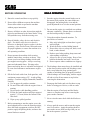
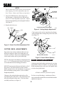
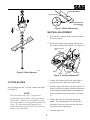
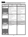
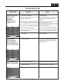
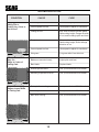
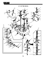
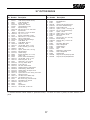
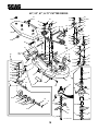
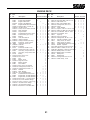
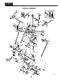
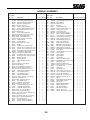
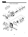
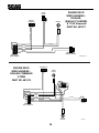
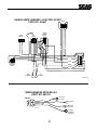
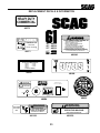
OPERATOR’S MANUAL
MODEL SWZ
THIS MANUAL CONTAINS THE OPERATING
INSTRUCTIONS AND SAFETY INFORMATION FOR YOUR SCAG MOWER. READING
THIS MANUAL CAN PROVIDE YOU WITH
ASSISTANCE IN MAINTENANCE AND ADJUSTMENT PROCEDURES TO KEEP YOUR
MOWER PERFORMING TO MAXIMUM EFFICIENCY. THE SPECIFIC MODELS THAT THIS
BOOK COVERS ARE CONTAINED ON THE
INSIDE COVER. BEFORE OPERATING YOUR
MACHINE, PLEASE READ ALL THE INFORMATION ENCLOSED.
PART NUMBER 03056
WARNING:
FAILURE TO FOLLOW SAFE OPERATING PRACTICES
MAY RESULT IN SERIOUS INJURY.
* Keep all shields in place, especially the grass discharge chute.
* Before performing any maintenance or service, stop the machine and
remove the spark plug wire and ignition key.
* If a mechanism becomes clogged, stop the engine before cleaning.
* Keep hands, feet and clothing away from power-driven parts.
* Read this manual completely as well as other manuals that came
with your mower.
* Keep others off the tractor (only one person at a time)
REMEMBER - YOUR MOWER IS ONLY AS SAFE AS THE OPERATOR!
Hazard control and accident prevention are dependent upon the awareness,
concern, prudence, and proper training of the personnel involved in the
operation, transport, maintenance, and storage of the equipment.
This manual covers the operating instructions
and illustrated parts list for:
SWZ36-14KA
SWZ36-15KH
SWZ48-14KA
SWZ48-15KH
SWZ48-17KA
SWZ-17KA
SWM-52E
SWM-61E
SWM-72E
with a serial number of 4040001-4049999
with a serial number of 4050001-4059999
with a serial number of 4060001-4069999
with a serial number of 4070001-4079999
with a serial number of 4080001-4089999
with a serial number of 4100001-4109999
with a serial number of 4110001-4119999
with a serial number of 4120001-4129999
with a serial number of 4130001-4139999
Always use the entire serial number listed on the serial number
tag when referring to this product.
TABLE OF CONTENTS
SUBJECT
PAGE
Introduction .................................................................................................. 1
General Safety Instructions .......................................................................... 1
Signal Words ............................................................................................... 1
Before Operating ......................................................................................... 2
While Operating ........................................................................................... 2
Maintenance and Storage ........................................................................... 3
Initial Run-In Procedures ............................................................................. 4
Mower Operation ......................................................................................... 4
Cutter Deck Belt Adjustments ...................................................................... 5
Cutter Deck Adjustments ............................................................................. 6
Blade Height Adjustments ........................................................................... 6
Cutter Blades ............................................................................................... 7
Neutral Adjustment ...................................................................................... 7
Steering Control Rod Adjustment ................................................................ 8
Tracking Adjustment .................................................................................... 8
Parking Brake .............................................................................................. 8
Lubrication and Maintenance Chart ............................................................ 9
Troubleshooting Cutting Conditions ............................................................ 10-12
Technical Specifications .............................................................................. 13-14
Notes .........................................................................................................................15
MEMBER
c
WE SUPPORT OPE
Equipment & Engine
Training Council
TECHNICIAN
CERTIFICATION
I
TABLE OF CONTENTS
(CONTINUED)
SUBJECT
PAGE
Illustrated Parts List
SWM-36"Cutter Deck ........................................................................ 16-17
SWM-48", 52", 61", 72" Cutter Decks...................................................... 18-19
Engine Deck................................................................................................ 20-21
Drive And Brake Components.................................................................. 22-23
Handle Assembly........................................................................................ 24-25
Hydraulic Assembly .......................................................................... 26-27
Hydraulic Pump Assembly ................................................................ 28-29
Engine Deck Wire Harness-Kohler (Single Cyl.) & 17KA................... 30
Engine Deck Wire Harness- Kohler Command V-Twin...................... 30
Handle Wire Harness-Electric Start......................................................... 31
Wire Harness W/Relay............................................................................... 31
Engine Deck Wire Harness-14 Kawasaki............................................... 32
Handle Wire Harness-Manual Start......................................................... 32
Replacement Decals.................................................................................. 33-35
Warranty Statement...............................................................Inside Back Cover
II
INTRODUCTION
SIGNAL WORDS
Your mower was built to the highest standards in the
industry. However, the prolonged life and maximum efficiency of your mower depends on you
following the operating, maintenance and adjustment instructions in this manual.
This symbol means “Attention! Become Alert!
Your Safety is Involved!" The symbol is used
with the following signal words to attract your
attention to safety messages found on the decals and
throughout this manual. The message that follows
the symbol contains important information about
safety. To avoid injury and possible death, carefully
read the message! Be sure to fully understand the
causes of possible injury or death.
We encourage you to contact your dealer for repairs.
All Scag dealers are informed of the latest methods
to service this equipment and provide prompt and
efficient service in the field or at their service shop.
They carry a full line of Scag service parts.
A replacement Operator's Manual is available from
your Scag Servicing Dealer or by contacting Scag
Power Equipment, Service Department, at P.O. Box
152, Mayville, WI 53050. Please indicate the
complete model and serial number of your Scag
product.
Signal Word:
It is a distinctive word on safety decals and throughout this manual that alerts the viewer to the existence
and relative degree of the hazard.
USE OF OTHER THAN ORIGINAL SCAG
REPLACEMENT PARTS WILL VOID THE
WARRANTY.
The “Right” and “Left”, “Front” and “Rear” of the
machine are referenced from the operator’s perspective when in the normal operating position and
facing the forward travel direction.
The signal word “DANGER” denotes that an extremely hazardous situation exists on or near the
machine that could result in high probability of
death or irreparable injury if proper precautions are
not taken.
GENERAL SAFETY INSTRUCTIONS
WARNING:
READ THIS OPERATOR'S MANUAL and
instructions furnished with attachments.
The signal word “WARNING” denotes that a hazard
exists on or near the machine that can result in injury
or death if proper precautions are not taken.
Perform only those maintenance procedures described in this manual. If major repairs are ever
needed or assistance is desired, contact an Authorized Scag Dealer. To ensure optimum performance
and safety, always purchase genuine SCAG replacement parts and accessories.
CAUTION:
The signal word “CAUTION” is a reminder of
safety practices on or near the machine that could
result in personal injury if proper precautions are
not taken.
Your safety and the safety of others depends significantly upon your knowledge and understanding of
all correct operating practices and procedures of this
machine.
1
BEFORE OPERATING
WHILE OPERA
TING
OPERATING
1. Know the controls and how to stop quickly.
1. Start the engine when the neutral latches are in
the neutral lock position, the cutter blades are
disengaged, the parking brake is on and the
speed adjustment lever is in the neutral position.
2. Do not allow children to operate the machine.
Do not allow adults to operate the machine
without proper instruction.
2. Do not run the engine in a confined area without
adequate ventilation. Exhaust fumes are hazardous and could possibly be deadly.
3. Remove all debris or other objects that might be
picked up and thrown by the cutter blades. Keep
all bystanders away from the mowing area.
3. Using the machine demands attention. To
prevent loss of control:
A. Mow only in daylight or when there is good
artificial light.
B. Watch for holes or other hidden hazards.
C. Do not drive close to a drop-off, ditch, creek
bank, or other hazard.
D. Reduce speed when making sharp turns and
when turning on hillsides.
E. Always be sure of your footing. Keep a firm
hold on the handles and walk---never run.
F. Do not operate where conditions are slippery.
4. Keep all shields, safety devices, and decals in
place. If a shield, safety device or decal is
defective or damaged, repair or replace it before
operating. Also, check all nuts, bolts and screws
for proper tightness, to assure the machine is in
safe operating condition.
5. Do not operate the machine while wearing
sandals, tennis shoes, sneakers or shorts. Also,
do not wear loose fitting clothing which could
get caught in moving parts. Always wear long
pants and substantial shoes. Wearing safety
glasses and safety shoes is advisable and required
by some local ordinances and insurance regulations.
4. The discharge chute must always be installed and
in the down position on the side discharge cutter
deck except when the Scag optional grass
catcher or mulching plate are properly installed.
If the discharge area should plug, shut the engine
off and wait for all movement to stop before
removing the obstruction.
6. Fill the fuel tank with clean, fresh gasoline, with
a minimum octane rating of 87. Avoid spilling
gasoline. Gasoline is highly flammable, handle it
carefully.
A. Use an approved gasoline container.
B. Do not fill the tank while the engine is hot or
running.
C. Do not smoke while handling gasoline.
D. Fill the fuel tank outdoors and up to approximately 1" (25 mm) below the bottom of the
filler neck.
E. Wipe up any spilled gasoline.
5. Disengage the blades and wait for them to stop
before crossing gravel drives, walks or roads.
6. Shut the engine off and wait until the blades
come to a complete stop before removing the
grass catcher container.
7. Never raise the cutter deck while the blades are
rotating.
7. Before attempting to start the engine, move the
speed adjustment lever into the neutral position,
move the blade engagement switch to the OFF
position, apply the parking brake, and move the
neutral latches to neutral.
8. Always park the mower and/or start the engine
on a level surface. Apply the parking brake to
prevent the mower from moving when you are
not in the operator’s position.
2
14. Use only Scag approved riding attachments.
9. If the cutting blades should strike a solid object or
the equipment should start to vibrate abnormally,
stop the engine, disconnect the spark plug wire, and
check immediately for the cause. Vibration is
generally a warning of trouble. Check the machine
for damaged or defective parts. Repair any damage
before starting the engine or operating the cutter
deck. Be sure the blades are in good condition and
the blade bolts are tight.
Scag Approved Riding Attachments:
RS-ZT
Using unapproved attachments, (especially
"stand-up" riding attachments) may be hazardous.
MAINTENANCE AND STORAGE
1. Disconnect the spark plug wire from the spark
plug to prevent accidental starting of the engine
when servicing, adjusting or storing the machine.
10. Reduce speed and exercise extreme caution on
slopes and in sharp turns to prevent tipping or
loss of control. Be especially cautious when
changing directions on slopes.
2. If the mower must be tipped to perform maintenance or adjustment, remove the battery, drain
the gasoline from the fuel tank and the oil from
the crankcase.
WARNING:
DO NOT operate on steep slopes. To check a
slope, attempt to back up it (with the cutter deck
down). If the machine can back up the slope
without the wheels slipping, reduce speed and
use extreme caution. ALWAYS FOLLOW OSHA
APPROVED OPERATION.
3. To reduce potential fire hazard, keep the engine
free of excessive grease, grass, leaves and accumulations of dirt.
4. Be sure the machine is in safe operating condition by keeping nuts, bolts, and screws tight.
Check the blade mounting bolts and nuts frequently to be sure they are tightened.
11. Do not touch the engine or muffler while the
engine is running or soon after it is stopped.
These areas could be hot enough to cause a burn.
5. If the engine must be running to perform a
maintenance adjustment, keep hands, feet,
clothing and other parts of the body away from
the cutter deck blades and other moving parts.
12. Before leaving the operator’s position or leaving
the mower unattended, move the speed adjustment lever into the neutral position, place the
neutral latches in the neutral lock position, apply
the parking brake, and move the blade engagement switch to OFF. Shut the engine OFF and
remove the key.
6. Do not overspeed the engine by changing governor settings. To be sure of safety and accuracy,
have an authorized dealer check maximum
engine speed with a tachometer.
7. The engine must be shut off before checking the
oil or adding oil to the crankcase.
13. Do not pass or stand on the grass discharge side
of any mower with the engine running. Stop
operation when another person approaches.
8. Allow the engine to cool before storing the
mower in any enclosure such as a garage or
storage shed. Make sure the fuel tank is empty if
the machine is to be stored in excess of 30 days.
Do not store the mower near any open flame or
where gasoline fumes may be ignited by a spark.
WARNING
FALLING HAZARD
USE ONLY SCAG APPROVED
RIDING ATTACHMENTS
SEE OPERATOR'S MANUAL
481109
3
9. Always store gasoline in a safety-approved, red
container.
MOWER OPERATION
1. Read and understand the safety instructions
before attempting to operate this machine.
10. Be careful when servicing the battery as it
contains acid, which is corrosive and could cause
burns to skin and clothing.
2. Before starting the engine:
* Check the oil level in the engine and the
hydraulic reservoir.
* Fill the fuel tank with clean, fresh, leadfree gasoline.
* Open the fuel valve on the bottom of the
fuel tank.
11. Batteries release explosive gases when being
charged or discharged. Keep batteries away
from any source of sparks and/or flame.
12. Make sure all hydraulic connections are tight and
all hydraulic hoses and lines are in good condition before starting the machine.
-NOTEUse gasoline with an octane rating no less than
87.
13. Hydraulic fluid is under high pressure. If you
need service on your hydraulic system, please
see your authorized Scag dealer.
* The speed adjustment lever must be in
NEUTRAL.
* The blade clutch switch must be in the OFF
position.
* The neutral latches must be in the neutral
lock position.
* The key switch must be on.
* The parking brake must be on.
INITIAL RUN-IN PROCEDURES
(FIRST DAY OF USE OR APPROXIMATELY 10 HOURS)
1. Check the belts for proper tension at 2, 4 and 8
hours. Adjust as needed.
3. Start the engine:
2. Check the steering control rods and the speed
control for neutral adjustment. (See Adjust
ments, page 6-8)
* Choke as required. If the engine is cold, pull
the choke knob out. When the engine starts,
slowly push the choke in. If the engine
stalls, repeat the above operation. When the
engine is warm, choking may not be necessary.
3. Check the tires for proper pressure.
Caster Wheels
25 psi.
Drive Wheels
15 psi.
4. Check for loose hardware. Tighten as needed.
4. Engage the cutter blades by pulling the blade
clutch switch into the ON position. Push the
switch to the OFF position to disengage the cutter
blades.
5. Check the safety switches for proper adjustment:
* The engine should crank and start if the
machine is in neutral, the PTO engagement switch is OFF and the parking brake
is ON.
6. Apply lubricant to all the grease fittings. Lubricant was applied at the factory. This is just a
precautionary check to make sure that all the
fittings have been lubricated.
PULL UP TO ENGAGE
PUSH DOWN TO DISENGAGE
390S0138
4
-NOTEWhen PTO is engaged or (possibly) disengaged,
a squealing sound from the underside of the
machine is normal. It is caused by the electric
clutch plates meshing as the mower comes up to
speed. For best equipment life, engage the
clutch with the engine at 1/2 throttle, not under
full load.
WARNING:
If you are not familiar with the operation of the
hydrostatic drive and zero turn feature, practice
turning and maneuvering with the hand controls
before engaging the blades.
Dump Valve Levers
(normal position)
Figure 1. Dump Valves
SGB112
CUTTER DECK BEL
T ADJUSTMENTS
BELT
5. Release the parking brake. Move the speed
adjustment lever to the desired mowing speed.
-NOTEThe hydro drive belt is spring loaded and does
not require adjustment.
-NOTETop speed is suggested only for transport!
6. While squeezing the steering brake levers with both
hands, release both neutral latches.
1. Remove the belt cover.
7. When the steering brake levers are released, the
machine will travel straight. To make a right turn,
squeeze the RH lever. To turn left, squeeze the LH
lever.
2. Adjust the cutter deck drive belt using a belt
tension gauge. Adjust the belt so that the belt
moves 1/2" with 10 pounds of pressure. Adjust
the tension by tightening or loosening the J-bolt
nut. (See figure 2)
END OF L-SHAPED
BRACKET
8. TO STOP, squeeze both levers, lock the neutral
latches, and move the speed adjustment lever to
neutral.
BELT
NUT
9. To move the machine in reverse, squeeze up on
both steering control levers.
"J" BOLT
ire pressure canWASHER
be adjusted for
10. To "freewheel" or move the machine around
without the engine running, turn the dump valve
levers located at the back of the pumps to the
"freewheel" positions (see Figure 1). To operate the
machine, the dump valve levers must be returned to
the closed positions.
CUTTER DECK DRIVE BELT TENSION
ALIGNMENT IDLER - L.H.
SC400G
Figure 2. Deck Drive Belt Adjustment
5
LOW CUT (1 3/4"- 3")
-NOTEDue to initial belt stretch and to prevent the belt
from slipping, check this adjustment after the
first 2 hours, 4 hours and 8 hours of operation.
MID RANGE
(2 1/2"- 3 3/4")
3. Adjust the RH blade drive belt using a belt
tension gauge. Adjust the belt so that the belt
moves 1/2" with 10 pounds of pressure. Adjust
the tension by tightening or loosening the J-bolt nut
(See figure 3).
HIGH CUT (3 1/4"- 4 1/2")
4. Replace the belt cover.
Nut
CUTTER DECK HEIGHT ADJUSTMENT
Washer
SC405G
Figure 4. Cutting Height Adjustment
Deck
Caster spacers also can be repositioned to change
cutting heights and to change the pitch of the deck.
(See figure 5)
"J" Bolt
PIN
SPACERS
Belt
Figure 3. Cutter Deck Belt Adjustment R.H.
CUTTER DECK ADJUSTMENTS
Due to the many cutting conditions that exist, it is
difficult to suggest a cutter deck setting that will
work for every lawn. There are two adjustments that
can be made on these decks, pitch and height.
PITCH is the angle of the blades (comparing front to
rear). A 1/4" downward pitch (front of deck down)
is recommended for best cutting performance.
HEIGHT is the nominal distance the blade is off of
the ground. This measurement is made with the
blades pointed side to side and distance is measured
between cutting tip and ground. (Also see Blade
Height Adjustment)
Changes to the cutting height can be achieved by
repositioning the cutter deck. (This adjustment will
also effect the pitch of the deck). There are three
available positions (see figure 4).
REPOSITIONING SPACERS
SC406G99
Figure 5. Caster Wheel Spacers
BLADE HEIGHT ADJUSTMENT
Adjusting the blade height can be done by moving
any number of the five smaller 1/4" spacers on the
blade mounting bolts to the top of the spindle shaft
or below the spindle shaft.
-NOTEAll blades should be positioned equally.
For best cut and discharge, a minimum of three
spacers should be installed between the blade and the
spindle (See figure 6).
6
ANGLE BLADE BACK
X
DO NOT CUT IN
X MUST NOT EXCEED
1/3 BLADE WIDTH
30
SC4O8G
Figure 7. Blade Sharpening
NEUTRAL ADJUSTMENT
1. Raise the drive wheels off the ground and block
the caster wheels.
2. Remove the speed control spring and the steering control rod from the machine. (See figure 8)
Steering Control
Rod
Bolts
SC407G
Spring
Figure 6. Blade Spacers
Bellcrank
Handle
SC160G
Figure 8. Neutral Adjustment
3. Loosen the wing nut and let the speed adjustment bearing lever fall away from the cam.
CUTTER BLADES
4. Start the engine and observe the drive wheels. If
the drive wheels are rotating, loosen the bolts on the
neutral adjustment handle and move the handle up
or down until the wheels are in neutral. (See figure
8)
Do not sharpen beyond 1/3 of the width of the blade.
(See figure 7)
-NOTEDress the blade with a file. Using a wheel
grinder may burn the blade. Check the balance
of the blade. If blades are out of balance, vibration and premature wear of spindle assembly can
occur. See your authorized Scag dealer for
blade balancing or special tools, if you choose to
balance your own blades.
5. Tighten the bolts on the neutral adjustment
handle. When tightening the bolts, hold the
bellcrank to prevent it from moving and throwing off the neutral adjustment.
6. Turn the engine off.
7
3. Tighten the bearing securing the speed adjustment
bearing lever and repeat on the opposite side.
STEERING CONTROL ROD
ADJUSTMENT
4. With the machine on a flat level surface, start the
engine and place the speed adjustment lever into
the speed that will most often be used.
-NOTEThis adjustment is made to allow the steering
control levers to be moved out of the neutral
latch without engaging reverse.
1. Connect the steering control rods into the steering control levers on the handle. Do not install
the hair pin at this time.
5. Squeeze the steering control levers and release
the neutral latch. Slowly release the steering
control levers, allowing the machine to move forward.
2. Turn the swivel joint on the steering control rods
until the swivel joint is centered in the slot in the
bellcrank.
6. If the machine pulls to one side, put the speed
adjustment lever back into the neutral position
and turn the engine off.
3. Remove the steering control rods from the
machine. Install the speed control spring onto
the swivel joint. Reinstall the steering control
rods onto the machine and secure using the hair
pins.
7. On the side that the machine pulled toward,
loosen the wing nut securing the speed adjustment bearing lever and move the bearing 1/16"
away from the cam. Start the engine and recheck
the tracking. Adjust as needed.
TRACKING ADJUSTMENT
8. If tracking cannot be achieved, contact your Scag
servicing dealer.
-NOTEBefore proceeding with this adjustment, be sure
that the tire pressures are correct. (see page 4)
and that the neutral adjustment and the steering
control rod adjustment have been completed.
PARKING BRAKE
1. Adjust the parking brake so that when the brake
hand lever is against the stop on the handle bar,
the brake levers on the brake shaft weldment are
against the stops on the engine deck.
1. Engage the neutral latch on both steering control
levers and move the speed adjustment lever into
the neutral position.
CAUTION:
2. Position the speed adjustment lever so that the
bearing just contacts the speed adjustment cam.
(See below)
Steering Control Rod
Swivel
Joint
Adjust the brake only enough to hold the
machine. Excessive force may cause damage
to the machine or brake components.
Speed Adjustment
Cam
2. Adjust the brake actuator rod on either side of
the machine to obtain proper brake adjustment.
Bearing
Speed
Adjustment
Bearing Lever
Speed Control Spring
Bellcrank
SC161G
8
LUBRICA
TION & MAINTENANCE
LUBRICATION
BREAK-IN
+ Grease spindle until grease comes out the relief valve
Compatible Greases:
Lidok EP #2 (found at industrial shops)
Ronex MP (Exxon service stations)
40 HOURS (WEEKLY)
Shell Alvania (Shell service stations)
Mobilux #2 (Mobil service stations)
100 HOURS (BIWEEKLY)
Super Lub M EP #2 (Conoco service stations)
8 HOURS (DAILY)
500 HRS OR ANNUALLY
COMMENTS
PROCEDURE
X
X
X
X
X
X
X
X
X
X
X
X
X
X
X
X
X
X
X
X
X
X
Check all hardware for proper tightness
Change engine oil and filter at 5 hours
Check engine oil
Remove debris from under belt cover
Sharpen cutter blades
Grease spindle bearings
Clean air filter
Check belt tension
Check tire pressure
Check battery level
Replace air filter
Grease caster wheel bearings
Grease caster wheel pivot shafts
Grease idler pulley bracket on cutter deck
Change hydrostatic oil filter
Change engine oil and filter
Grease idler arm pivots
Grease brake hand lever
Grease brake actuator levers
Check all hardware for proper tightness
Adjust air gap on electric clutch
Drain hydraulic system and replace oil
Do not over fill
More often if needed
More often if needed
+ US Lithium MP White Grease 2125
More often if needed
Adjust as needed
Add or adjust as required
Adjust as needed
More often if needed
Chassis grease
Chassis grease
Chassis grease
Clean area before removing the filter
See engine manufacturer information
Chassis grease
Chassis grease
Chassis grease
Contact your Scag dealer for information about
making this adjustment.
9
TROUBLESHOOTING CUTTING CONDITIONS
CAUSE
CONDITION
Stringers - Occasional
Blades of Uncut
Grass
Width of Deck
CURE
Low engine RPM
Run engine at full 3600 RPM
Ground speed too fast
Slow speed to adjust for conditions
Wet grass
Cut grass after it has dried out
Dull blades, incorrect sharpening
Sharpen blades
Deck plugged, grass accumulation
Clean underside of deck
Belts slipping
Adjust belt tensions
Dull, worn blades
Sharpen blades
Incorrect blade sharpening
Sharpen blades
Low engine RPM
Run engine at full 3600 RPM
Belt slipping
Adjust belt tension
Deck plugged, grass accumulation
Clean underside of deck
Ground speed too fast
Slow speed to adjust for conditions
Wet grass
Cut grass after it has dried out
Bent blades
Replace blades
Not enough overlapping
between rows
Increase the overlap of each
pass
SGB020
Streaking - Strips of
Uncut Grass in Cutting
Path
Width of Deck
SGB018
Streaking - Strips of
Uncut Grass Between
Cutting Paths
Width
of
Deck
SGB019
Width
of
Deck
10
TROUBLESHOOTING
CAUSE
CONDITION
Uneven Cut on Flat
Ground - Wavy
High-Low
Appearance,
Scalloped Cut, or
Rough Contour
CURE
Lift worn off of blade
Replace blade
Blade upside down
Mount with cutting edge toward
ground
Deck plugged, grass accumulation
Clean underside of deck
Too much blade angle (deck pitch)
Adjust pitch and level
Deck mounted improperly
See your authorized SCAG dealer
Bent spindle area
See your authorized SCAG dealer
Dull blade
Sharpen blade
Uneven ground
May need to reduce ground speed,
raise cutting height, and/or change
direction of cut
Tire pressures not equal
Check and adjust tire pressure
Wheels uneven
Check and adjust tire pressure
Deck mounted incorrectly
See your authorized SCAG dealer
Width of Deck
SGB020
Uneven Cut on
Uneven Ground Wavy Appearance,
High-Low Scalloped
Cut, or Rough Contour
Width of Deck
SGB021
Sloping Ridge Across
Width of Cutting Path
Width of Deck
SGB023
11
TROUBLESHOOTING
CAUSE
CONDITION
Scalping - Blades
Hitting Dirt or
Cutting Very Close to
the Ground
Width of Deck
CURE
Low tire pressures
Check and adjust pressures
Ground speed too fast
Slow speed to adjust for conditions
Cutting too low
May need to reduce ground speed,
raise cutting height, change direction
of cut, and/or change pitch and level
Rough terrain
May need to reduce ground speed,
raise cutting height, and/or change
direction of cut
Ground speed too fast
Slow speed to adjust for conditions
Wet grass
Cut grass after it has dried out
Blades not mounted evenly
Adjust pitch and level
Bent blade
Replace blade
Internal spindle failure
See your authorized SCAG dealer
Mounting of spindle incorrect
See your authorized SCAG dealer
Bent spindle mounting area
See your authorized SCAG dealer
Internal spindle failure
See your authorized SCAG dealer
Bent deck housing
See your authorized SCAG dealer
SGB022
Step Cut
Ridge in Center of
Cutting Path
Width of Deck
SGB024
Slope Cut - Sloping
Ridges Across Width
of Cutting Path
Width of Deck
SGB025
12
TECHNICAL SPECIFICATIONS
ENGINES
General Type:
Brand:
Models:
Horsepower:
Type:
Displacement:
Cylinders:
Governor:
Exhaust Group:
Fuel Pump Group:
Oil Pump Group:
Valve Group:
Starter/Electrical:
Charging System:
Heavy duty industrial/commercial
Kohler, Kawasaki,
Kohler CV15T, CVE 20;Kaw. FC420V;
Kohler 15HP& 20HP; Kaw. 14HP; Kaw. 17HP
4 cycle gas, vertical shaft engines
Kohler: 15HP = 426cc, 20 HP= 624cc
Kawasaki: 14HP = 423cc, 17HP = 494cc
Varied - see manufacturer's specifications
Mechanical type governor with variable speed control set
at 3600 rpm (+75 rpm), idle set at 1200 rpm (+75 rpm)
Single exhaust canister muffler
Varied - See manufacturer's specifications
Varied - See manufacturer's specifications
Varied - See manufacturer's specifications
Electronic Ignition with recoil starter or 12 volt battery with
alternator, solid state ignition with key start
15 amp
ENGINE DECK
Thickness:
Fuel Tank:
Drive Wheels/Tires:
Brakes:
Axles:
Handle Bars:
7 gauge steel
5 gallon (19.0 litres) seamless polyethylene
16x6.50-8 four-ply pneumatic tubeless, radius edge
Dynamic braking through hydro drive system
1" tapered
1-1/4" diameter
DRIVE SYSTEM
Type:
Hydro Pumps:
Drive Wheel Motors:
Hydro Fluid Cooling Group:
Steering / Travel Control::
Parking Brakes:
Dump Valves:
Axles:
Wire Harness:
Safety Group:
Forward Speed Range:
Reverse Speed Range:
Hydro drive with two variable displacement pumps and two
cast-iron high torque motors
Two Hydro-Gear Model BDP 10L pumps with dump valves for
movement without running the engine
Two 12 cu. inch cast-iron high torque motors
Heavy-duty cooling radiator, 7 qt. capacity cooling
reservoir, uses, SAE 10W30 fluid and 10 micron filter
Independent handle controls for each wheel, squeeze to move
from forward to neutral to reverse, neutral lock lever, speed
range controlled with single lever (patented design), in-field
tracking adjustment with no tools necessary
7.5" drum, band brake, one on each wheel
Allows for movement without engine running
1" tapered motor shafts
14 gauge wire
Handle actuated operator presence system (patented design),
blade / clutch and transmission interlock to engine kill
0 to 7.4 mph
0 to 3.0 mph
Date of Issue: May, 1998
Specifications Subject to Change Without Notice
13
TECHNICAL SPECIFICATIONS
CUTTER DECKS
Type:
Construction:
Cutting Width:
Cutting Height Adjustment:
Cutter Blades:
Blade Engagement:
Discharge Opening:
Caster Wheels:
Spindles:
Spindle Pulleys:
Idler Pulley:
Idler Arm:
Cutter Deck Belts:
(CON'T)
SWM 36, SWM 48, SWM 52, SWM 61, SWM 72
Out-front design with anti-scalp rollers
SWM36,48: 7-gauge steel with 7-gauge (3/16") steel skirt
SWM52,61,72:10-gauge steel with 7-gauge (3/16") steel
skirt
35.5" (90.2 cm), 48.0 (122.0 cm), 52.0 " (132.0 cm),
61.0 " (155.0 cm), 71.5" (181.6 cm)
Adjustable from 1-3/4" to 4-1/4" in 1/4" increments
.204 thick, milled edge, 5150 alloy steel
SWM 36: Two (2) 18" SWM 48: Three (3) 16.5"
SWM 52: Three (3) 18" SWM 61: Three (3) 21"
SM72: Three (3) 24" blades
Electric blade brake clutch with instrument panel switch
Extra wide 11.5", 13.75 " discharge opening with hinged
chute
9.4 x 3.5 smooth tread flotation, inner tubes, split rims, roller
bearings, with quick pin removal
Cast housing, taper roller bearing, low maintenance with
top access grease fitting and grease overfill relief poppet
Cast-iron with easily removed taper hubs
5" diameter pulley, welded and riveted construction,
1-3/8" O.D. Bearing
Heavy duty idler arm of 1/4" channel steel
B-section with Kevlar cord
ADDITIONAL SPECIFICATIONS
OPTIONAL ITEMS/ATTACHMENTS
Fabric Grass Catcher:
Metal Grass Catcher:
Steerable Sulky:
Mulching Plate:
GC-F4 Grass Catcher with 4 cubic ft. capacity
GC-4D Grass Catcher with 4 cubic ft. capacity and rope pull
dump or pick-up and dump
RS-ZT Steerable Sulky with padded seat and full articulation
for zero-radius turning
Steel plate fits over discharge opening. No blade change or
or removal required. Installs and removes in the field.
APPROXIMATE DIMENSIONS
SWM36 SWM48 SWM52 SWM61 SWM72
Length:
Length with Grass Catcher:
Tracking Width:
Width:
Width (with discharge chute up):
With with grass catcher:
Height:
Height with grass catcher:
Weight
Weight with grass catcher:
Turning Radius:
74.0"
74.0"
37.0"
54.5"
37.5"
55.0"
40.5"
40.5"
510 lbs.
550 lbs.
Zero
Date of Issue: May, 1998
Specifications Subject To Change Without Notice
14
74.0"
74.0"
42.0"
60.0"
53.0"
69.0"
40.5"
40.5"
550 lbs.
590 lbs.
Zero
74.0"
74.0"
42.0"
60.0"
53.0"
69.0"
40.5"
40.5"
590 lbs.
630 lbs.
Zero
76.0"
76.0"
42.0"
70.0"
63.0"
80.0"
40.5"
40.5"
625 lbs.
665lbs.
Zero
76.0"
76.0"
42.0"
81.0"
74.0"
91.0"
40.5"
40.5"
695lbs.
730 lbs.
Zero
NOTES
15
32" & 36" CUTTER DECKS
41
69
9
45
47
43
11
41
69
44
44
45
68
61
59
11
46
46A
43
58
57
22
42
53
A
41
39
39A
40
42
48
7
60
58
54
14
55
50
13
56
37
18
49
52
38
36
51
A
49
2
19
37
20
21
14
55
35
40
22
21
8
20
23
24
1
1A
14
25
62
27
28
26
35
10
5
66
29
22
6
34
32
31
33
4
11
3
12
30
31
11
64
5
15
15A
16
63
67
17
SW-SWZ99CD36
16
65
36" CUTTER DECKS
Ref. Part
No. Number
1
2
3
4
5
6
7
8
9
10
11
12
13
14
15
15A
16
17
18
19
20
21
22
23
24
25
26
27
28
29
NS
30
31
32
33
34
35
36
37
38
39
40
41
42
43
44
461131
46631
43312
48307-08
481022
43294
04001-108
43298
04001-77
04063-08
43278
04001-10
481050
04019-03
48108
48185
04040-10
04001-41
46079
04066-01
43037-01
48100-01
48114-04
46082
45006
43022
04001-37
04021-07
48307
48307-02
48006-03
48307-04
48006-07
48006-06
48114-03
48006-05
04017-16
461054
04021-10
04001-09
46797
04041-07
04029-03
48924
48926
04001-01
Description
Cutter Deck (Includes Decals)
Cutter Spindle Assy.
Spacer, Outside
Tapered Nut, 5/16-24
Tapered Bearing (Two)
Spindle Housing
Bolt, 5/16-18 x 4-1/4" Hex Head
Spindle Shaft
Bolt, 3/8-16 x 3-1/2" Hex Head
Key, 1/4 x 1/4 x 2"
Spacer, Cutter Blade - Small
Bolt,5/16-18 x 1-1/4" Hex Head
Spring, Chutte Return
Nut 5/16-18 Serrated Flange
Cutter Blade, 18"
Cutter Blade, 18 Hi Lift
Flatwasher, 5/8 W
Hex Hd. Bolt, 5/8-11 x 9-1/2"
Caster Assembly (Inc.19-28)
Quick Pin
Spacer, Caster Yoke, 1/2" long
Bronze Bearing
Grease Fitting
Support Assembly (Inc. 21-23)
Caster Yoke
Sleeve, Caster Wheel Bearing
Hex Hd. Bolt, 1/2-13 x 5-1/2"
Elastic Stop Nut, 1/2-13
Wheel Assy. (Inc.4, 29-34)
Tire only, Caster Wheel
Inner Tube only
Rim Pair, Caster Wheel
Retainer, Bearing, Caster Wheel
Roller Bearing, Caster Wheel
Grease Fitting, 45 degree 1/4-28
Hub Assembly
Cpscrw,5/16-18 x 3/4" Ser.Flg. Hex Head
Discharge Chute
Hex Nut, 5/16-18 Elastic Stop
Hex Hd Bolt, 5/16-18 x 1"
Belt Cover Assy (Includes Decal)
Flat Washer, 3/8" Special
Wing Nut, 3/8-16
Pulley
Tapered Hub
Hex Hd. Bolt, 1/4-20 x 3/4"
Ref. Part
No. Number
45
46
47
48
49
50
51
52
53
54
55
56
57
58
59
60
61
62
63
64
65
66
67
68
69
69
04020-09
48204
43077
04021-05
04019-04
04004-02
04017-42
04019-05
43277
04041-12
04021-09
45423
46748
48100-02
04050-05
44078
48269
481024
43297
43296
481035
48677
481025
48098
04029-04
04029-04
Description
Hex Nut, 5/8-11
Belt, Blade Drive
Spacer
Hex Nut, 3/8-16 Center Locknut
Nut, 3/8-16 Serrated Flange
Support, Belt Cover
Cpscrw, 7/16-14 x 1"Ser.Flg. HH
Nut, 7/16-14 Serrated Flange
Spacer, J-Hook
Washer, 3/8 x 1-1/2 x 16 GA
Elastic Stop Nut, 3/8-16
Idler Pivot
Idler Arm Assy. (Inc. 22 & 58)
Bronze Bearing
Retaining Ring, 1-1/8" Ext. ”E”
J-Hook
Idler Pulley, Belt Clutch
Seal, Cutter Spindle
Spindle Bushing
Spacer, Inside
Nut,
Relief Fitting, Cutter Spindle
Seal, Cutter Spindle
Spindle Shield
Wing Nut, 3/8-16 (Small) Top Side
Wing Nut, 3/8-16 (Small) RH Side
* Common hardware which should be purchased locally. All bolts are Grade 5 plated, all other fasteners zinc
plated.
17
48", 52", 61", & 72" CUTTER DECKS
41
73
22
59
56, 56A
61
51
44
45
40
45
44
11
43
43
11
48 45
7
51
44 58
60
47
4
39
40
11
41
46
46A
46B
41
62, 62A
63
43
64
65
49
82
61
14
76
78
42
42A
42B
52
13
40
63
9
37
74
77
67
7
38
36
36A
18
50
A
55 54
57
51
40
19
37
A
35
20
68
77
35
14
64
14
51
75
21
50
7
21
14
20
23
24
8
35
2
25
27
66
1
28
80
26
79
10
5
53
69
7
6
29
34
11
32
31
33
83
11
30
70
12
3
5
15
15A
31
16
71
81
17
SW-SWZ99CD48"
18
72
48, 52, 61, & 72" CUTTER DECKS
Ref. Part
No. No.
Description
1
1
1
1
2
3
4
5
6
7
8
9
10
11
12
13
14
15
15
15
15
15A
15A
15A
16
17
18
19
20
21
22
23
24
25
26
27
28
29
NS
30
31
32
33
34
35
36
36A
37
38
39
39
39
39
39
40
41
42
42A
42B
43
Cutter Deck (Includes decals)
Cutter Deck (Includes decals)
Cutter Deck (Includes decals)
Cutter Deck (Includes decals)
Spindle Assembly
Spacer, Inside
Pulley
Tapered Bearing (Two)
Spindle Housing
Grease Fitting Str. 5/16
Spindle Shaft, Tapered Brng
Idler Pivot
Key, 1/4 x 1/4 x 2"
Spacer, Cutter Blade - Small
Bolt, 5/16-18 x 1-1/4" Hex Head
Bolt, 5/16-18 x 4-1/4" Hex Head
Serrated Flange Nut, 5/16-18
Cutter Blade 16-1/2"
Cutter Blade 18"
Cutter Blade 21"
Cutter Blade 24"
Cutter Blade 16-1/2 Hi Lift
Cutter Blade 18 Hi Lift
Cutter Blade 21 Hi Lift
Flatwasher,5/8" (.688 x 1.75 x .134)
Hex Head Bolt, 5/8-11 x 9-1/2"
Caster Assembly, (incl.19-28 & 7)
Quick Pin
Spacer, Caster Yoke, 1/2" thick
Bronze Bearing
Spindle Shield
Support Assembly, (incl. 21-23)
Caster Yoke
Sleeve, Caster Wheel Bearing
Hex Hd Bolt, 1/2-13 x 5-1/2"
Elastic Stop Nut, 1/2-13
Wheel Assy. (incl. 29-34,81)
Tire only, Caster Wheel
Inner Tube only, Caster Wheel
Rim Pair, Caster Wheel
Bearing Retainer, Caster Wheel
Roller Bearing, Caster Wheel
Grease Fitting 45 deg., 1/4-28
Hub Assembly, (incl. bolts)
Capscrew, 5/16-18 x 3/4"
Discharge Chute
Discharge Chute
Nut, 5/16-18 Elastic Elastic Stop
Bolt, 5/16-18 x 1" Hex Head
Belt Cover (Includes decals)
Belt Cover (Includes decals) 17KA
Belt Cover (Includes decals)
Belt Cover (Includes decals)
Belt Cover (Includes decals)
Flat Washer, 3/8" Special
Wing Nut, 3/8-16 (Large)
Pulley
Pulley
Pulley
Tapered Hub
461132
461134
461138
46608
46631
43296
48924
481022
43294
48114-04
43298
45037
04063-08
43278
04001-10
04001-108
04019-03
48110
48108
48111
48112
48184
48185
48304
04040-10
04001-41
46079
04066-01
43037-01
48100-01
48098
46082
45006
43022
04001-37
04021-07
48307
48307-02
48006-03
48307-04
48006-07
48006-06
48114-03
48006-05
04017-16
461055
461054
04021-04
04001-09
46798
461095
46804
46805
46848
04041-07
04029-03
48924
48753
48967
48926
Ref. Part
No. No.
48 52 61 72
44
45
46
46A
46B
47
47
47
47
48
48
48
48
49
50
51
52
53
54
55
56
56A
57
58
59
60
61
62
62A
63
64
65
66
67
68
69
70
71
72
73
74
75
76
77
78
79
80
81
82
83
x
x
x
x
x
x
x
x
x
x
x
x
x
x
x
x
x
x
x
x
x
x
x
x
x
x
x
x
x
x
x
x
x
x
x
x
x
x
x
x
x
x
x
x
x
x
x
x
x
x
x
x
x
x
x
x
x
x
x
x
x
x
x
x
x
x
x
x
x
x
x
x
x
x
x
x
x
x
x
x
x
x
x
x
x
x
x
x
x
x
x
x
x
x
x
x
x
x
x
x
x
x
x
x
x
x
x
x
x
x
x
x
x
x x
x x
x x
x x
x x
x x
x x
x x
x x
x x
x x
x x
x x
x x
x x
x x
x x
x x
x x
x x
x x
x x
x
x
x
x
x
x
x
x
x
x
x
x
x
x
x
x
x
x
x
x
x
x
x
19
Description
04001-01
04020-09
48923
48940
48966
48087
48285
48265
48295
48089
48286
48088
48296
04021-05
04019-04
04021-09
04004-02
04001-08
04017-42
04019-05
04041-08
04041-08S
44078
48181
04050-02
46081
48100-05
43028
44078
43077
04041-12
04001-46
481024
46748
43277
48677
43312
43297
481035
04029-04
04001-77
45329
48269
48100-02
04050-05
48038
45944
481025
481050
48307-08
48 52 61 72
Bolt, 1/4-20 x 3/4" Hex Head
Nut, 5/8-11 Hex
Pulley, Double
Pulley, Double
Pulley, Double
Belt, RH Blade Drive
Belt, RH Blade Drive
Belt, RH Blade Drive
Belt, RH Blade Drive
Belt, Blade Drive
Belt, Blade Drive
Belt, Blade Drive
Belt, Blade Drive
Nut, 3/8-16, Nut Centerlock
Nut, 3/8-16, Serrated Flange
Nut, 3/8-16 Elastic Stop
Support, Belt Cover
Bolt, 5/16-18 x 1/2" Hex Head
Cpscrw,7/16-14 x 1"Ser Flng H Hd
Nut, 7/16-14 Serrated Flange
Flat Washer 3/4" Special
Flat Washer 3/4" Special
J-Hook
Idler Pulley, “V” Groove
Retaining Ring, 3/4" Ext.”E”
Idler Arm Assy. (Incl. 7 & 61)
Bronze Bearing
J-Rod, Idler Pulley
J-Rod, Idler Pulley
Spacer, J-Rod
Washer, 3/8 x 1-1/2 x 16 ga.
Bolt, 3/8-16 x 2-1/4" Hex Head
Seal, Cutter Spindle
Idler Arm Assy (Includes 22&77)
Spacer, J-Rod
Reiief Fitting, Cutter Spindle
Spacer, Outside, Cutter Spindle
Spindle Bushing
Nut, Cutter Spindle
Wing Nut, 3/8-16 (Small) Top Side
Bolt, 3/8-16 x 3-1/2" Hex Head
Idler Pivot
Idler Pulley, Belt Clutch
Bronze Bearing
Retaining Ring
Guide Roller
Roller Shaft
Seal, Cutter Spindle
Spring, Chute Return
Nut, 3/8-24 Tapered
x
x
x
x
x
x
x
x
x
x
x
x
x
x
x
x
x
x
x
x
x
x
x
x
x
x
x
x
x
x
x
x
x
x
x
x
x
x
x
x
x
x
x
x
x
x
x
x
x
x
x
x
x
x
x
x
x
x
x
x
x
x
x
x
x
x
x
x
x
x
x
x
x
x
x
x
x
x
x
x
x
x
x
x
x
x
x
x
x
x
x
x
x
x
x
x
x
x
x
x
x
x
x
x
x
x
x
x
x
x
x
x
x
x
x
x
x
x
x
x
x
x
x
x
x
x
x
x
x
x
x
x
x
x
x
x
x
x
x
x
x
x
x
x
x
x
x
x
x
x
x
x
x
x
x
x
x
x
x
x
x
x
x
x
ENGINE DECK
5
58
7
4
55
6
2
48
7
1
53
51
8
18
16
50
3
17
38
16
10
37
33
61
BLK
60
RED
9
11
45
63
34
34A
32
42
45
11A
56
65
43
15
ELECTRIC
12 START ONLY
12A
14
20
19
57
13
11
59
35
49
38
38
39
47
47A
64
35
23
27
39
41
22
21
54
62
40
45
43
28
44
26
45
43
25
29
24
46
38
43
30
31
030441698
20
ENGINE DECK
Ref. Part
No. No.
Description
1
1
1
1
2
3
4
5
6
7
8
9
10
11
11A
12
12A
13
14
15
16
17
18
19
20
21
22
23
24
25
26
27
28
29
30
31
32
33
34
34A
35
36
37
38
39
40
Engine 14KA Kawasaki
Engine 15KH Kohler
Engine 17KA Kawasaki
Engine 20CVE Kohler Command
Retaining Ring, 1/2" Ext. "E"
Hex Nut, 1/4-20
Screw, 1/4-20 x 2" Rnd. Hd. Phil.
Strap, Fuel Tank
Cap, Fuel Tank
Pad, Rubber-Fuel Tank - Upper
Fuel Tank Assy. (incl. 9, 10)
Bushing
Valve, Fuel Shut-off
Clamp, Fuel Hose
Clamp, Fuel Hose, (KA Only)
Fuel Hose, 1/4 ID x 20" KA
Fuel Hose, 1/4 ID x 23"
Cable Tie
Fuel Filter
Fuel Hose, 7/32 ID x 3-1/2"
Capscrew, #10-32 x 1 Soc. Hd.
Lever Assy., Pump Control -LH
Lever Assy., Pump Control -RH
Battery
Bolt, 1/4-20 x .50"
Nut, 1/4-20
Pad
Battery Cover
Wing Nut, 1/4-20
Battery Support
Pad, Rubber
Bolt, 1/4-20 x 6" Carriage
Carriage Bolt, 5/16-18 x 2"
Carriage Bolt, 5/16-18 x 1"
Stiffener
Plate, Backing
Nut, 1/4-20 Elastic Stop
Pad, Rubber-Fuel Tank, Lower
Engine Deck, 16" Wide, W/Decls.
Engine Deck, 20" Wide, W/Decls.
Bolt,1/4-20 x 1-1/4" Hex Head
Nut, 1/4-20 Serrated Flange
Capscr., 5/16-18 x 1.25 Sr. Flg.
Nut, 5/16-18 Serr. Flange
Nut, 3/8-16 Serr. Flange
Bolt, 3/8-16 x 2-3/4" Hex Head
48842
48844
481066
48971
04050-10
04020-02
04010-10
421239
481603
48292
46846
48309
48308
48059-01
48059-02
48058
48058
48028-05
48057-02
48179
04015-06
46323
46324
48015
04001-44
04020-02
48099
42392
04029-01
45685
48661
04003-01
04003-28
04003-04
422553
422552
04021-08
48205
46946
46947
04003-09
04019-02
04017-18
04019-03
04019-04
04001-22
14KA 15KH 17KA 20CVE
x
x
x
x
x
x
x
x
x
x
x
x
x
x
x
x
x
x
x
x
x
x
x
x
x
x
x
x
x
x
x
x
x
x
x
x
x
x
x
x
x
x
x
x
x
x
x
x
x
x
x
x
x
x
x
x
x
x
x
x
x
x
x
x
x
x
x
x
x
x
x
x
x
x
x
x
x
x
x
x
x
x
x
x
x
x
x
x
x
x
x
x
x
x
x
x
x
x
x
x
x
x
x
x
x
x
x
x
x
x
x
x
x
x
x
x
21
Ref. Part
No. No.
41
42
43
44
45
46
47
47A
48
49
50
51
52
53
54
54
55
56
57
58
59
60
61
62
63
64
65
Description
04001-08 Hex Head Bolt, 5/16-18 x .75"
04040-14 Flat Washer 1/4"
04021-10 Nut, 5/16-18 Elastic Stop
04003-04 Carrage Bolt, 5/16-18 x 1"
48030-09 Clamp
421370
Clutch Bracket
04017-19 Capscr, 5/16-18 x 1.50" Sr. Flg.
04002-01 Metric HH Bolt, M8-1.25 x M30
04031-09 Lock Washer, 5/16 Int. Tooth
04030-03 Lock Washer, 5/16
48257
Pipe Cap
48402-04 Pipe, 4.75" Nipple
04003-09 Carrage Bolt, 1/4-20 x 1-1/4"
481717
Wire Hrns. Adapter, 17KA
45418
Pulley Guard, 16" Frame
45419
Pulley Guard, 20" Frame
45283
Shaft Weldment, RH Pump Cntl.
421390
Bracket, Capacitor
21013-2064 Condenser (order from Kaw. )
04002-07 Metric H H Bolt, 8-1.25 x 10
21066-2071 Regulator, (order from Kaw.)M
48029-02 Battery Cable, 31.5" Red
48029-14 Battery Cable, 31.5 Black
421703
Battery Box
48126
Rubber Boot
04003-12 Carrage Bolt, 5/16-18 x .75
48030-10 Cable Clamp, .75 ID
14KA 15KH 17KA 20CVE
x
x
x
x
x
x
x
x
x
x
x
x
x
x
x
x
x
x
x
x
x
x
x
x
x
x
x
x
x
x
x
x
x
x
x
x
x
x
x
x
x
x
x
x
x
x
x
x
x
x
x
x
x
x
x
x
x
x
DRIVE AND BRAKE COMPONENTS
1
2
3, 3A
5
4
7
8
9
6
10, 10A
7
A
49
53
51
40
11
43
44
42
41
42
2
47
45
50 52
48
49
4
50
46
7
39
38
1
A
2
11
48
12
36
47
35
37
34
21
20
19
24
24A
13
14
15
18
33
25
26
32
23
17
16
22
27
30
29
28A
28B
28C
SWZ99D&BC
31
22
DRIVE AND BRAKE COMPONENTS
Ref. Part
No. No.
1
2
3
3A
4
5
6
7
8
9
10
10A
11
12
13
14
15
16
17
18
19
20
21
22
23
24
24A
25
26
27
04050-02
04001-19
45842
45854
04062-01
04003-12
44126
04019-04
43415
48114-05
45860
45861
04001-46
481618
48004-04
422214
48679
04028-01
481502
422215
04008-01
46928
481470
04063-07
481416
48553
48587
461073
04041-28
04030-05
Description
Retaining Ring, 3/4 Ext. "E"
Bolt, 3/8-16 x 1" Hex Head
Brake Shaft Assy. Wlmt.Small
Brake Shaft Assy. Wlmt.Large
Hair Pin Cotter, .094 x 1.62
Carrage Bolt, 5/16-18 x .75"
Rod, Brake Lower
Nut, 3/8-16 Serr. Flange
Bushing, Brake
Grease Fitting
Brake Actuator Wlmt., LH
Brake Actuator Wlmt., RH
Bolt, 3/8-16 x 2-1/4"
Tire, 16 x 6.50, 4 ply
Rim Assy
Lock Washer, Wheel Motor
Hex Castle Nut, 3/4-28 UNEF
Nut, Lug
Wheel Assy., (incl. 31,32)
Brake Drum
1/2-20 Serrated Bolt
Hub, Wheel
Brake Band, 7.5"
Key, 3/16 X .75 Woodruff
Wheel Motor
Belt, Pump Drive (Sm Frame)
Belt, Pump Drive (Lg Frame)
Electric Clutch
Flat Washer .469 x 1.75 x .25
Lock Washer, 7/16
14KA 14KH 17KA 20CVE
x
x
x
x
x
x
x
x
x
x
x
x
x
x
x
x
x
x
x
x
x
x
x
x
x
x
x
x
x
x
x
x
x
x
x
x
x
x
x
x
x
x
x
x
x
x
x
x
x
x
x
x
x
x
x
x
x
x
x
x
x
x
x
x
x
x
x
x
x
x
x
x
x
x
x
x
x
x
x
x
x
x
x
x
x
x
x
x
x
x
x
x
x
x
x
x
x
x
x
x
x
x
x
x
x
x
x
x
x
x
x
x
x
Ref. Part
No. No.
28A
28B
29
30
31
32
33
34
35
36
37
38
38
39
40
41
42
43
44
45
46
47
48
49
50
51
52
53
23
Description
04002-05 Hex Head Bolt, M10-1.5 x 65
04001-149 Hex Head Bolt, 7/16-20 x 2.00"
422534
Plate, Backing
48030-09 Clamp
04021-10 Nut, 5/16-18 Elastic Stop
481716
Rubber Pad, Clutch Stop
422533
Retainer, Clutch Stop
04001-12 Hex Head Bolt, 5/16-18 x 1.75"
481665
Pulley, Pump Drive Engine
04001-13 Hex Head Bolt, 5/16-18 x 2.75"
04021-05 Nut, 3/8-16 Center Lock
04041-08 Washer, 3/4-.766 x 1.2 x .06
04041-08S Washer, 3/4-.766 x 1.2 x .035
48100-05 Bushing, 3/4 Sintered
48114-04 Grease Fitting, Str. 1/4-28
48051
Spring, Pump Belt Idler
04019-03 Nut, 5/16-18 Serr. Flange
04063-24 Key, 1/4x1/4x2.75" Clutch Mtg.
04063-01 Key, 1/4x1/4x1.25" Pulley Mtg.
04041-07 Flat Washer, 3/8
48473
Pulley, Idler Pump Drive
48586
Pulley, Pump Shaft
04012-04 Setscrew, 5/16-18 x 3/8"
04030-04 Lockwasher, 3/8
04063-14 Key, 5.0 x 5.0 x 25mm
45212
Pivot, Idler Arm
43032
Swivel Joint
46940
Arm, Idler
14KA 14KH 17KA 20CVE
x
x
x
x
x
x
x
x
x
x
x
x
x
x
x
x
x
x
x
x
x
x
x
x
x
x
x
x
x
x
x
x
x
x
x
x
x
x
x
x
x
x
x
x
x
x
x
x
x
x
x
x
x
x
x
x
x
x
x
x
x
x
x
x
x
x
x
x
x
x
x
x
x
x
x
x
x
x
x
x
x
x
x
x
x
x
x
x
x
x
x
x
x
x
x
x
x
x
x
x
x
x
x
x
x
x
x
x
HANDLE ASSEMBLY
89
74
16
19
19A
11
68
81
15
90 83
16A
71
76
A
8
7
6
20
REF.
75
17
A
25
18
18A
11
2
12
9
13
19
19A
5
4
3
1
10
24
16A
21
22
23
24
15
14
26
87
82
41
31
20
60
27
35
86
37
30
32
61
40
42
63
63A
28
60
45
87
3
92 80
34
69
69A
67
61
66
88 85
3
36
40
38
29
11
78
37
91
34
93
79
39
39A
78
40
37
43
65
60
94
43
25
49
60 48
44
46
38
64
64A 24
47
3
51
59
52
61
73
56
58
50
11
70
54
56
62
57
55
53
24
72
55
73
SWZ99HA
HANDLE ASSEMBLY
Ref. Part
No. No.
Description
1
1
2
3
4
5
6
7
8
9
10
11
12
13
13A
14
15
16
16A
16A
17
18
18A
19
19A
20
20A
21
22
23
24
25
26
27
28
29
30
31
32
33
34
35
36
37
38
39
39A
40
41
42
43
44
45
46
47
48
Upper Handle Wlmt. W/Decals
Upper Handle Wlmt. W/Decals
Quadrant, Speed Control
Hairpin, .094 x 1.19
Lever, Speed Adjustment
Bushing, Speed Adjustment Lever
Hex Head Bolt, 3/8-16 x 1-1/2"
Ball Plunger
Knob, Speed Adjustment
Capscrew, 1/4-20 x 3/4" FHHS
Nut, 1/4-20 Elastic Stop
Nut, 5/16-18 Elastic Stop
Screw, #10-32 x 1/2" PW HD
Throttle Control
Throttle Control
Nut, #10-32 Serr. Flange
Bushing
Handle, Oper. Presence-RH
Handle, Oper. Presence-LH (20")
Handle, Oper. Presence-LH (16")
Switch,Elec.Clutch Eng. (incl.Nut)
Wire Harness, Manual Start
Wire Harness, Electric Start
Key Switch, Manual Srt. (incl. Hdw)
Key Switch, Elec. Start (incl. Hdw.)
Neutral Latch-RH
Neutral Latch-LH
Switch, Neutral Interlock
Grip
Washer, Curved Spring
Flat Washer
Lock Washer,1/4" Int. Tooth
Hex Head Bolt, 5/16-18 x 2"
Hex Hd. Bolt, 5/16-18 x 2-1/2"
Lever, Steering Control (incl. 29)
Grip, Steering Control
Rod, Steering Control
Spring, Handle Return
Capscr., 3/8-16 x 1" Ser. Flange
Lock Washer, !/4"
Nut, 3/8-16 Serr. Flange
Rod Speed Control
Bellcrank, Speed Control
Setscrew, 1/4-28 x 1/4"
Cam, Speed Control (incl. SS)
Jackshaft, Speed Control
Jackshaft, Speed Control
Key, 1/8 x 1/2" Woodruff
Nut, 3/8-16 Elastic Stop
Pivot, Pump Ctrl. (incl.Bshg & Zrk)
Bushing, 1/2" ID
Capscrew, 5/16-18 x 1" Serr. Flg.
Nut, 5/16-18 Serrated Flange
Bar, Speed Control
Spacer, Speed Ctrl. Bearing
Bearing, Speed Ctrl. Bellcrank
461128
461129
42675
04062-02
45282
43086
04001-20
48493-01
48092
04014-01
04021-08
04021-10
04010-01
481071
48946
04019-01
48312
45572
45571
45573
481687
481680
481681
48609
48798
46942
46941
48717
48159
04032-01
04040-15
04031-08
04001-17
04001-53
46744
48492
44050
48951
04017-27
04030-02
04019-04
44051
45279
04012-02
46335
43166
43155
04063-13
04021-10
46336
48100-04
04017-17
04019-03
42730
43161
48409
14KA 15KH 17KA 20CVE
x
x
x
x
x
x
x
x
x
x
x
x
x
x
x
x
x
x
x
x
x
x
x
x
x
x
x
x
x
x
x
x
x
x
x
x
x
x
x
x
x
x
x
x
x
x
x
x
x
x
x
x
x
x
x
x
x
x
x
x
x
x
x
x
x
x
x
x
x
x
x
x
x
x
x
x
x
x
x
x
x
x
x
x
x
x
x
x
x
x
x
x
x
x
x
x
x
x
x
x
x
x
x
x
x
x
x
x
x
x
x
x
x
x
x
x
x
x
x
x
x
x
x
x
x
x
x
x
x
x
x
x
x
x
x
x
x
x
x
x
x
x
x
x
x
x
x
x
x
x
x
x
x
x
x
x
x
x
x
x
x
x
x
x
x
x
x
x
x
x
x
x
x
x
x
x
x
x
x
x
x
x
x
x
x
x
x
x
x
x
x
x
x
x
x
x
x
x
x
x
x
x
x
x
Ref. Part
No. No.
Description
49
50
51
52
53
54
55
56
57
58
59
60
61
62
63
63A
64
64A
65
66
67
68
69
69A
70
71
72
73
74
75
76
77
78
79
80
81
82
83
84
85
86
87
88
89
90
91
92
93
94
Hex Head Bolt, 5/16-18 x 1-3/4"
Spring, Return
Knob, 5/16-18
Bushing
Handle, Neutral Adj
Drive Pin, 5/32 x 7/8 Type U
HH Bolt,5/16-18 x 3/4"
Lock Washer, 5/16
Nut, 5/16-18 Serr. Flange
Bearing, Ball Neutral Return
Cam, Neutral (incl. grease ftng.)
Grease Fitting, 1/4-28 UNF
Retaining Ring, 5/8 Ext. "E"
Hex Head Bolt, 5/16-18 x 1"
Shaft, Pump Control-LH
Shaft, Pump Control-RH
Bellcrank, Pump Control-LH
Bellcrank, Pump Control-RH
Retaining Ring, 1/2 Ext. "E"
Flat Washer, 15/16x25/64x12 ga
Deck, Engine
Hex Head Bolt, 5/16-18 x 1-1/4"
Choke Control
Choke Control
Spring, Return
Fuse Holder
Swivel Joint, Steering Rod
Flat Washer (.344 x .688 x .065)
Blade Fuse, 20A
Nut, #10-32 Elastic Stop
Screw, #10-32 x 1-1/2" Phillips
Pin, Neutral Lock
Swivel Joint
Rod, Brake Lever
Hex Hd. Bolt, 3/8-16 x 1 3/4
Soc. Hd. Capscrew, #8-32 x 1/2
Nut, 3/8-16 Elastic Stop
Washer #8-.170 x .375 x .032
Retaining Ring, 5/8 Ext, "E"
Spacer
Parking Brake Lever with Grip
Switch, Parking Brake
Nut, 3/8-24
Bushing, bearing Retainer
Bearing, Neutral Lock
Grip, Parking Brake
Ball Joint, RH Thread
Hairpin, .094 x 1.62
Bracket, Choke Mtg. (16" Only)
04001-69
48494-02
481517-02
43308
45292
04065-05
04001-08
04030-03
04019-03
48224
46747
48114-05
04050-01
04001-09
45295
45283
45642
45643
04050-10
04041-07
By Ref.
04001-10
481278
481072
481057
42413
43306
04040-04
48298
04021-01
04010-03
43305
43032
44125
04001-21
04015-13
04021-09
04041-23
04050-01
43212
46954
481476
04020-14
481411
481420
48342
48464
04062-01
481622
14KA 15KH 17KA 20CVE
* Common hardware which should be purchased locally. All bolts Grade 5 plated, all other fasteners zinc plated.
25
x
x
x
x
x
x
x
x
x
x
x
x
x
x
x
x
x
x
x
x
x
x
x
x
x
x
x
x
x
x
x
x
x
x
x
x
x
x
x
x
x
x
x
x
x
x
x
x
x
x
x
x
x
x
x
x
x
x
x
x
x
x
x
x
x
x
x
x
x
x
x
x
x
x
x
x
x
x
x
x
x
x
x
x
x
x
x
x
x
x
x
x
x
x
x
x
x
x
x
x
x
x
x
x
x
x
x
x
x
x
x
x
x
x
x
x
x
x
x
x
x
x
x
x
x
x
x
x
x
x
x
x
x
x
x
x
x
x
x
x
x
x
x
x
x
x
x
x
x
x
x
x
x
x
x
x
x
x
x
x
x
x
x
x
x
x
x
x
x
x
x
x
x
x
x
x
x
x
x
x
x
x
x
x
HYDRAULIC ASSEMBLY
1
2
K
B
5
B
E
21
13
7
4
4
3
4
29
8
D
12
J
10
19
H
J
4
22
D
31
5
13
C
23
18
18A
17
28
24
32
3
20
11
10
30
A
35
10 28 11
H
E
6
5
22
35
C
A
13
7
4
6
15
4
14
16
10
29
8
28 11
K
19
33
12
28
10
34
11
10
9
F
G
26
25
FG
10
19
10
19
21
27
030441798
26
HYDRAULIC ASSEMBLY
Ref. Part
No. Number
Description
1
2
2
3
4
5
6
7
8
9
10
11
12
13
14
15
16
17
18
18A
19
20
21
22
23
24
25
25
26
27
28
29
30
31
32
33
34
35
Cap, Oil Reservoir
Oil Reservoir (small Frame)
Oil Reservior (Large Frame)
Elbow, 90 deg. Female 1/4 NPT to 1/4 JIC Male
Coupling, 7/16-20 SAE Flare Swivel to 1/4" Hose Push On
Hose, 1/4" ID - 12" Long (Order By The Inch)
Elbow, 90 deg. 7/16-20 JIC to 9/16-18 "O" Ring
O-Ring
Pump, Hydro-Gear BDP-10L117
Bolt, Carriage, 3/8-16 x 1-1/4"
Hose, Pump to Motor
O-Ring
Elbow, 90 deg., 7/16-20 JIC x 7/16-20 O-Ring
Hose, 1/4" ID - 10" Long (Order By The Inch)
Oil Filter Base
Elbow, 90 deg. Male 3/4-16 JIC to 1/2" Male NPT
Spacer, Oil Filter Base (20" Frame)
Coupling, 3/4-16 SAE to 1/2" Hose Push On
Capscrew, 5/16-18 x .75" (For 16") Serr. Flange
Capscrew, 5/16-18 x 2.25" (For 20") Serr. Flange
O-Ring
Elbow, 90 deg. Male 1/4 NPT to 1/4 Hose Push On
Nut, 5/16-18 Serr. Flange
Hose, Formed 1/2" ID
Coupling, 1/4 straight Male NPT to 1/4 Hose Push On
Bolt, 5/16-18 x 3/4" Carriage
Engine Deck (16" Wide) W/Decals
Engine Deck (20" Wide) W/Decals
Nut, 3/8-16 Serr Flange
Oil Filter
Elbow, 45 Deg.-3/4-16 JIC Male x Male 3/4-16 O-Ring
O-Ring
Coupling, 3/8 Pipe to 1/2 Push-on
T-Fitting, 3/8 NPT
Plug, 3/8-18 NPTF Magnetic
Screw, 1/4-20 x 2.0" Round Head Phillips
Nut, 1/4-20 Elastic Stop
Clamp, .87 max dia.
48535
46618
46619
48484-01
48353-02
48482
48350-04
48603-06
48551
04003-11
481265
48603-02
48350-03
48482
48471-02
48489-02
43096
48936-03
04017-16
04017-22
48603-04
48486-01
04019-03
481562
48352-02
04003-12
46946
46947
04019-04
48462-01
48485-01
48603-03
481537-02
48491
48731-01
04010-10
04021-08
48136-05
14KA 15KH
x
x
x
x
x
x
x
x
x
x
x
x
x
x
x
x
x
x
x
x
x
x
x
x
x
x
x
x
x
x
x
x
x
x
x
x
x
x
x
x
x
x
x
x
x
x
x
x
x
x
x
x
x
x
x
x
x
x
x
x
x
x
x
x
x
x
17KA 20CVE
* Common hardware which should be purchased locally. All bolts Grade 5 plated, all other fasteners zinc plated.
27
x
x
x
x
x
x
x
x
x
x
x
x
x
x
x
x
x
x
x
x
x
x
x
x
x
x
x
x
x
x
x
x
x
x
x
x
x
x
x
x
x
x
x
x
x
x
x
x
x
x
x
x
x
x
x
x
x
x
x
x
x
x
x
x
x
x
x
x
x
x
x
x
HYDRAULIC PUMP ASSEMBLY
30
26
it
e
lS
u
rha
K
al
25
e
Ov
24
23
22
27
28
1
29
19
20
21
17
16
3
15
18
11
2
14
12
13
5
6
7
8
11
10
9
4
SC165G
28
HYDRAULIC PUMP ASSEMBLY
Ref. Part
No. Number
Description
1
2
3
4
5
6
7
8
9
10
11
12
13
14
15
16
17
18
19
20
21
22
23
24
25
26
27
28
29
30
Housing Kit (Incl. Housing, Journal Bearing)
End Cap
Straight Headless Pin
Socket Head Screw
End Cap Gasket
Charge Pump Kit (Incl. Charge Cover, Gerotor Assy., O-Ring)
Gerotor Assembly
O-Ring
Charge Relief Valve Kit
Socket Head Screw
Check Valve Kit (Incl. Check Plug, Spring, O-Ring, Orifice Check Valve)
Bypass Valve Kit (Incl. Bypass Valve, O-Ring, Back-up Ring)
Backup Ring
Cylinder Block Kit
Block Spring
Block Thrust Washer
Roller Thrust Bearing
Swash Plate
Trunnion Arm
Guide Slot
Cradle Bearing
Lip Seal
Pump Shaft
Ball Bearing
Retaining Ring
Lip Seal
Retaining Ring
Spacer
Shaft Kit (Incl. Pump Shaft, Ball Bearing, Retaining Ring)
Overhaul Seal Kit (Incl. Gasket, Trunnion Seal, Input Shaft Seal, Charge Pump O-Ring)
HG 2513017
HG 2513016
HG 9004800-2506
HG 9007314-0810
HG 2003067
HG 2513027
HG 50273
HG 9004101-1340
HG 2510064
HG 50095
HG 2510027
HG 2513030
HG 9006110-0120
HG 70079
HG 2003014
HG 2003017
HG 2003044
HG 2003087
HG 2003005
HG 2000015
HG 2003023
HG 9008000-0126
HG 2003020
HG 2003043
HG 2003016
HG 9008000-0128
HG 2003052
HG 2003018
HG 2513038
HG 2513018
* Common hardware which should be purchased locally. All bolts Grade 5 plated, all other fasteners zinc plated.
29
BLADE
CLUTCH
NEUTRAL
INTERLOCK
BLACK W/RED STRIPE
GROUND
ENGINE DECK
WIRE HARNESS KOHLER,
(SINGLE CYLINDER)
& 17 HP Kawasaki
PART NO. 481073
BLACK
E
A
BLACK
F
B
G
C
H
D
BLUE
WHITE
WHITE
YELLOW
WIRE HARNESS
ADAPTER - ENGINE
INSTRUMENT
PANEL HARNESS
SWZ99SC421G
TRANSMISSION
ENGINE DECK
WIRE HARNESS KOHLER COMMAND
V-TWIN
PART NO. 481075
ENGINE
GROUND
TO ENGINE
BLACK W/RED STRIPE
RED
E
A
F
B
G C
H
D
GREEN
BLACK
BLUE
WHITE
WHITE
YELLOW
BLACK
ELECTRIC
CLUTCH
TO INSTRUMENT
PANEL CONNECTOR
STARTER
SOLENOID
30
SC422G
HANDLE WIRE HARNESS - ELECTRIC START
FUSES
PART NO. 481681
YELLOW W/RED STRIPE
GREEN
YELLOW
WHITE
WHITE
BLACK W/RED STRIPE
MOWER
ENGAGE
SWITCH
KEY
SWITCH
BRAKE
SWITCH
BLACK
BLACK W/RED STRIPE
RED
GREEN
A
BLACK
B
F
C
G
D
H
E
WHITE
RED
BLACK
RED
BLUE
TO
OPERATOR
PRESENCE
SWITCH
YELLOW
TO ENGINE
DECK WIRE
HARNESS
BLACK W/RED STRIPE
RED W/ YEL STRIPE
NEG
HOURMETER
POS
HOURMETER
SWZ99-481681
WIRE HARNESS WITH RELAY
PART NO. 481275
To Engine
Ground
RELAY
BLACK
GREEN
To Starter
BLUE
RED
To Blue Wire
From Engine
SC481275
To Starter
Red Battery
Cable Post
31
ENGINE DECK WIRE HARNESS KAWASAKI
PART NO. 481074
NEUTRAL
INTERLOCK
BLACK W/RED STRIPE
E
A
BLACK
F
B
G
C
H
D
BLUE
WHITE
WHITE
YELLOW
REGULATOR
RED
RED
ENGINE
BLACK
BLADE
CLUTCH
BLACK
INSTRUMENT
PANEL HARNESS
SWZ99SC417G
GROUND
BRAKE
SWITCH
MOWER
ENGAGE
SWITCH
BLACK W/RED STRIPE
WHITE
KEY
SWITCH
HANDLE WIRE HARNESS MANUAL START
PART NO. 481680
WHITE
BLACK W/RED STRIPE
BLACK
BLACK
BLUE
WHITE
BLACK W/RED STRIPE
TO
OPERATOR
PRESENCE
SWITCH
NEG
HOURMETER
YELLOW
BLACK
YELLOW
A
E
B
F
C
G
D
H
TO ENGINE
DECK WIRE
HARNESS
POS
HOURMETER
SWZ99-481680
32
REPLACEMENT DECALS & INFORMATION
HEAVY DUTY
COMMERCIAL
48072
48072
48314
WARNING
DANGER
ROTATING BLADES AND BELTS
SPINNING BLADE
KEEP CLEAR
CONTACT CAN INJURE
48071
48071
481040
PARKING
BRAKE
MANUFACTURED UNDER ONE OR MORE
OF THE FOLLOWING PATENTS:
CHOKE
FAST
4,991,382
4,998,948
4,118,617
4,487,006
4,885,903
4,920,733
4,967,543
KEEP HANDS, FEET & CLOTHING CLEAR
KEEP ALL GUARDS IN PLACE
SHUT OFF ENGINE & DISENGAGE BLADE
CLUTCH BEFORE SERVICING
CLEAR AREA OF DEBRIS BEFORE MOWING
USE CAUTION IN DIRECTING DISCHARGE
KEEP BYSTANDERS, CHILDREN & PETS AWAY
READ INSTRUCTION MANUAL BEFORE OPERATING
DO NOT OPERATE WITHOUT DISCHARGE CHUTE, MULCHING
481040
KIT, OR ENTIRE GRASS CATCHER INSTALLED
36" - 48316
48" - 48318
52" - 48319
61" - 48320
72" - 48327
OFF
PATENTS PENDING
ON
SLOW
48656
481414
CAUTION
MOWER DECK ON
BEFORE OPERATING
PULL OUT TO ENGAGE
READ OPERATORS
MANUAL AND SAFETY
INSTRUCTIONS
CAUTION
ON
KEEP BYSTANDERS AWAY
PUSH IN TO DISENGAGE
OFF
48404
48481684
48404
481684
WARNING
WARNING
MOUNT RIDING
ATTACHMENT
HERE
FALLING HAZARD
USE ONLY SCAG APPROVED
RIDING ATTACHMENTS
INSTALL BELT COVER BEFORE
OPERATING MACHINE
SEE OPERATOR'S MANUAL
READ OPERATOR'S MANUAL
481109
481039
481109
33
481039
REPLACEMENT DECALS & INFORMATION
PARKING
BRAKE
CHOKE
FAST
OFF
ON
SLOW
481415
PARKING
BRAKE
FAST
OFF
ON
SLOW
481423
PARKING
BRAKE
FAST
OFF
ON
SLOW
481438
34
TRACKING ADJUSTMENT
FAST
CONTROL ROD
ADJUSTMENT
REVERSE
SEE
OPERATOR'S
MANUAL
NEUTRAL
ADJUSTMENT
OIL
481425
FORWARD
481425
SEE OPERATOR'S MANUAL
SPEED
CONTROL
481080
SLOW
N
NEUTRAL
481124
481124
48514 - 20"
48555 - 16"
35
LIMITED WARRANTY-COMMERCIAL EQUIPMENT
Any part of the Scag commercial mower manufactured by Scag Power Equipment and found, in the reasonable judgment of Scag, to be defective in materials or workmanship, will be repaired or replaced by an Authorized Scag Service
Dealer without charge for parts and labor. This warranty is limited to the original purchaser and is not transferable.
Proof of purchase will be required by the dealer to substantiate any warranty claims. All warranty work must be
performed by an Authorized Scag Service Dealer.
This warranty is limited to the following specified periods from the date of the original retail purchase for defects in
materials or workmanship:
* Wear items including drive belts, blades, hoses and tires are warranted for 90 days.
* Batteries are covered for 90 days.
* Frame, deck, and structural components including oil reservoir, fittings, and oil cooler
are warranted for 1 year.
* Engines and electric starters are covered by the manufacturer’s warranty period.
* Drive system components are warranted for 1 year by the component manufacturer, in
conjunction with Scag Power Equipment. (Excluding fittings, hoses, cooling system,
oil reservoir, drive belts).
* Electric clutches have a Limited Warranty for 2 years. (Parts and labor 1st year; Parts Only
2nd year)
* Cutter Spindle Assemblies 46631 have a Limited Warranty for three years (Parts and
labor 1st year; Parts only 2nd and 3rd year).
Any Scag product used for rental purposes is covered by a 90 day warranty.
The Scag mower, including any defective part must be returned to an Authorized Scag Service Dealer within the
warranty period. The expense of delivering the mower to the dealer for warranty work and the expense of returning it
to the owner after repair will be paid for by the owner. Scag’s responsibility is limited to making the required repairs
and no claim of breach of warranty shall be cause for cancellation or rescission of the contract of sale of any Scag
mower.
This warranty does not cover any mower that has been subject to misuse, neglect, negligence, or accident, or that has
been operated in any way contrary to the operating instructions as specified in the Operator’s Manual. The warranty
does not apply to any damage to the mower that is the result of improper maintenance, or to any mower or parts that
have not been assembled or installed as specified in the Operator’s Manual and Assembly Manual. The warranty does
not cover any mower that has been altered or modified, changing performance or durability. In addition, the warranty
does not extend to repairs made necessary by normal wear, or by the use of parts or accessories which, in the reasonable
judgment of Scag, are either incompatible with the Scag mower or adversely affect its operation, performance or
durability.
Scag Power Equipment reserves the right to change or improve the design of any mower without assuming any obligation to modify any mower previously manufactured.
All other implied warranties are limited in duration to the one (1) year warranty period or ninety (90) days for mowers
used for rental purpose. Accordingly, any such implied warranties including merchantability, fitness for a particular
purpose, or otherwise, are disclaimed in their entirety after the expiration of the appropriate one year or ninety day
warranty period. Scag’s obligation under this warranty is strictly and exclusively limited to the repair or replacement
of defective parts and Scag does not assume or authorize anyone to assume for them any other obligation. Some states
do not allow limitations on how long an implied warranty lasts, so the above limitation may not apply to you.
Scag assumes no responsibility for incidental, consequential or other damages including, but not limited to, expense for
gasoline, expense of delivering the mower to an Authorized Scag Service Dealer and expense of returning it to the
owner, mechanic’s travel time, telephone or telegram charges, rental of a like product during the time warranty repairs
are being performed, travel, loss or damage to personal property, loss of revenue, loss of use of the mower, loss of time
or inconvenience. Some states do not allow the exclusion or limitation of incidental or consequential damages, so the
above limitation or exclusion may not apply to you.
This warranty gives you specific legal rights, and you may also have other rights which vary from state to state.
© 1999
SCAG POWER EQUIPMENT
DIVISION OF METALCRAFT OF MAYVILLE, INC.
PART NO. 03056
PRINTED1/99
PRINTED IN USA


![(平成20年)4月号 [PDF:124KB]](http://vs1.manualzilla.com/store/data/006650380_2-a52ad6733916606e35d653f74df2a09e-150x150.png)