1
Owner's Manual
ICRAFTSMAN'I
20 HP
ELECTRIC START
46" MOWER
6 SPEED
GARDEN TRACTOR
Model No.
917.272953
•
•
•
•
•
Safety
Assembly
Operation
Maintenance
Repair Parts
This product has a low emission engine which operates
differently from previously built engines. Before you start the englne, read and understand this Owner's Manual.
CAUTION:
Read and follow all Safety
Rules and Instructions before
operating this equipment,
For answers to yoUr questions
about this product, Call:
1-800-659-5917
Sear• Craftsman Help Line
5 am - 5 pro, Man - Sat
SEARS, ROEBUCK AND CO., HOFFMAN ESTATES, IL 60179
Visit our Craftsmanwebsita:www.sears.condcraftsman
Warranty ...............................................
2
Safety Rules .........................................
3
Product Specifications .......................... 6
Assembly ..............................................
8
Operation ............................................
12
Maintenance Schedule ...................... 18
Maintenance .......................................
18
Service and Adjustments .................... 22
Storage ...............................................
29
Troubleshooting ................................. 30
Repair Parts ........................................
34
Parts Ordedng ..................... Back Cover
LIMITED TWO YEAR WARRANTY ON CRAFTSMAN
RIDING EQUIPMENT
PARTS
For two (2) years from the date of pumhase, if this Craftsman Riding Equipment is
maintained, lubricated and tuned up according to the instructions in the owner's
manual, Sears will repair or replace, free of charge, any parts found to be defective in
material or workmanship. Warranty service is available free of charge by taking your
Craftsman riding equipment to your nearest Sears Service Center. In-home warranty
service is available but a trip charge will apply. This warranty applies only while this
product is in the United States.
This Warrantydoes not cover:
• Expendableitemswhich become worn duringnormal use, such as blades, spark
plugs,air cleaners, belts and oil filters.
• Tire replacementor repair caused by puncturesfrom outsideobjects,such as nails,
thorns,stumps,or glass.
• Repairs necessary because of operatorabuse, includingbut not limitedto, damage
caused by towingobjectsbeyond the capabilityof the ddingequipment,impacting
objectsthat bend the frame or crankshaft,or over speedingthe engine.
• Repairs necessarybecause of operatornegligence,includingbut not limitedto,
electricaland mechanicaldamage caused by improperstorage, failure to use the
propergrade and amount of engine oil, failure to keep the deck clear of flammable
debris,or the failure to maintainthe equipmentaccordingto the instructionscontained in the owner's manual.
• Engine (fuel system) cleaningor repairscaused by fuel determinedto be contaminated or oxidized(stale). In general,fuel shouldbe used withinthirty(30) days of its
pumhase date.
• Ridingequipmentused for commercialor rental purposes.
LIMITED 90 DAY WARRANTY ON BATTERY
For ninety (90) days from date of pumhase, if any battery included with this dding
equipment proves defective in material or workmanship and our testing determines the
battery will not hold a charge, Sears will replace the battery at no charge. Warranty
service is available free of charge by taking your Craftsman dding equipment to your
nearest Sears Service Center. In-home warranty service is available but a tdp charge
will apply. This warranty applies only while this product is in the United States.
TO LOCATE THE NEAREST SEARS SERVICE CENTER OR TO SCHEDULE IN-HOME
WARRANTY SERVICE, SIMPLY CONTACT SEARS AT t-800-4-MY-HOME
This Warrantygives you specificlegal dghts,and you may also have other rightswhich
may varyfrom stateto state.
Sears, Roebuck and Co., D/817 WA, Hoffman Estates, IL 60179
IMPORTANT:
Thiscutting
machine
is capable
ofamputating
handsandfeet
and
throwinq objects. Failure to observe the following safety instructions could result in
senous injury or death.
II. SLOPE OPERATION
I. GENERAL OPERATION
• Read, understand,and follow all
instructionsin the manual and on the
machinebefore starting.
, Only allow responsibleadults, who are
familiar with the instructions,to operate
the machine.
• Clear the area of objectssuch as
rocks,toys,wire, etc., whichcouldbe
pickedup and thrown by the blade.
• Be sure the area isclear of other
people before mowing. Stop machine
if anyone entersthe area.
• Never carry passengers.
• Do not mow in reverse unlessabsolutelynecessary. Always look down
and behind before and while backing.
• Be aware of the mower discharge
directionand do not point it at anyone.
Do not operatethe mower without
eitherthe entiregrass catcheror the
guard in place.
• Slow down before turning.
• Never leave a runningmachine
unattended. Alwaysturn off blades,set
parkingbrake, stop engine,and
remove keys before dismounting.
• Turn off bladeswhen not mowing.
• Stop engine before removinggrass
catcher or uncloggingchute.
• Mow only in daylightor good artificial
light.
• Do not operatethe machinewhile
under the influenceof alcoholor drugs.
• Watch for trafficwhen operatingnear or
crossingroadways.
• Use extra care when loadingor
unloadingthe machineintoa traileror
truck.
• Data indicatesthat operators,age 60
years and above, are involvedin a
large percentage Of ddingmowerrelated injuries. These operators
shouldevaluate their abilityto operate
the ridingmower safely enoughto
protectthemselvesand othersfrom
serious injury.
Slopesam a majorfactor relatedto loss-ofcontroland tipover accidents, which can
resultin severe injuryor death. All slopes
requireextracaution. Ifyoucannotbackup
the stopeor if you feel uneasy on it, do not
mow it.
DO:
• Mow up and down slopes, not across.
• Remove obstacles such as rocks, tree
limbs, etc.
• Watch for holes, ruts, or bumps.
Uneven terrain,could overturn the
machine. Ta/I grass can hide obstacles.
• Use slow speed. Choose a low gear
so that you will not have to stop or shift
while on the slope.
• Follow the manufacturer's recommendations for wheel weights or counterweights to improve stability.
• Use extra cam with grass catchers or
other attachments. These can change
the stability of the machine.
• Keep all movement on the slopes s/ow
and gradual Do not make sudden
changes in speed or direction.
• Avoid starting or stopping on a slope, if
tires lose traction, disengage the
blades and proceed slowly straight
downithe slope.
DO NOT:
• Do not turn on slopes unless neceSsary, and then, tum slowly and gradually downhill, if possible.
Do not mow near. drep-offs, ditches, or
embankments. The mower could
suddenly turn over if a wheel is over
the edge of a cliff or ditch, or if an edge
caves in.
• Do not mow on wet grass. Reduced
traction could cause sliding.
• Do not try to stabilize the machine by
putting your foot on the ground.
• Do not use grass catcher on steep
slopes.
3
III. CHILDREN
Tragic accidents can occur if the operator
is not alert to the presence of children.
Children are often attracted to the
machine and the mowing activity. Never
assume that children will remain where
you
last saw
themout
.... Of the mowing area
Keep
children
and under the watchful care of '.another
responsible adutt.
• Be alert and rum machine off if children
enter the area.
• Before and when backing, look behind
and down for small children.
• Never carry children. They maY fair off
and be seriously injured or interfere
with safe machine operation:
• Never allow children to operate the
machine.
• Use extra care when approaching blind
corners, shrubs, trees, or other objects
that may obscure vision.
IV, SERVICE
• Use extra care in handling gasotine
and other fuels. They are flammable
and vapors are explosive.
-Use only an approved container.
-Never remove gas cap or add fuel
with the engine running. Allow
engine to cool before refueling. Do
not smoke.
-Never refuel the machine indoors.
• Be sure the area is clear of other
people before mowing. Stop machine if
anyone enters the area,
• Never carry passengers or chitdren
even with the blades off.
• Do not mow in reverse unless absolutely necessary. Always look down
and behind before and while backing.
• Never carry children. They may tall off
and be seriously injured or interfere
with safe machine operation.
• Keep children out of the mowing area
end under the watchful care of another
responsible adult.
•
•
•
•
•
•
•
•
•
- Never store the machine or fuel
container inside where there is an
open flame, such as a water heater.
Never run a machine inside a closed
area.
Keep nuts and bolts, especially blade
attachment bolts, tight and keep
equipment in good condition.
Never tamper with safety devices.
Check their proper operatlori reguiar_J.
Keep machine free of grass, leaves, or
other debris build-up. Clean oil or fuel
spillage. Allow machine to cool before
storing.
Stop and inspect the equipment if you
strike an object. Repair, if necessary,
before restarting.
Never make adjustments or repairs
with the engine running.
Grass catcher components are subject
to wear, damage, and deterioration.
which coutd expose moving parts or
allow objects to be thrown. Frequently
check components and replace with
manufacturer's recommended parts,
when necessary.
Mower blades are sharp and can cut.
Wrap the blade(s) or wear gloves, and
use extra caution when servicing them.
Check brake operation frequently.
Adjust and service as required.
• Be alert and tum machine off if children
enter the area.
• Before and when backing, look behind
and down for small children.
• Mow up and down slopes (15 ° Max),
not across.
• Remove obstacles such as rocks, tree
limbs, etc.
• Watch for holes, ruts, or bumps.
Uneven terrain could overturn the
machine. Tall grass can hide obstacles.
4
• Use slow speed. Choose a low gear so
that you will not have to stop or shift
while on the slope.
• Avoid starting or stopping on a slope. If
tiros lose traction, disengage the
blades and proceed slowly straight
down the slope.
• If machine stops while going uphill,
disengage blades, shift into reverse
and back down slowly.
• Do not turn on slopes unless necessary, and then, turn slowly and gradually downhill, if possible.
_. CAUTION: Tow onlythe attachments
that are recommendedby and comply
with specificationsof the manufacturerof
your tractor. Use commonsense when
towing. Operate onlyat the towest
possiblespeed when on a slope. Too
heavy of a load, while on a slope, is
dangerous. Tires can losetractionwith
the groundand cause you to !ose control
of yourtractor.
_WARNING: Engine exhaust,some of
itsconstituents,and certainvehicle
componentscontainor emit chemicals
knownto the State OfCaliforniato cause
cancer and birthdefectsor other repro*
ductive harm.
,_Look for this symbol to point out
important safety precautions. It means
CAUTION!!! BECOME ALERT!!! YOUR
SAFETY IS INVOLVED.
_WARNING: Batteryposts,terminals
and relatedaccessoriescontain lead and
lead compounds,chemicalsknownto the
State of Californiato cause cancerand
birthdefectsor other reproductive harm.
Wash hands after handling.
,_ CAUTION: In order to prevent
accidental starting when setting up,
transporting, adjusting or making repairs,
always disconnect spark plug wire and
place wire where it cannot contact spark
plug.
_, CAUTION: Do not coast down a hill
in neutral, you may lose control of the
tractor.
5
PRODUCT
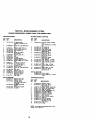
SPECIFICATIONS
GASOLINE
CAPACITY
ANDTYPE:
3.5 GALLONS
UNLEADED
REGULAR
OtLTYPE
SAE 10W30
_,PI-SF-SJ):
OIL CAPACITY:
(ABOVE 32°F)
SAE 5W-30
(BELOW 32°F)
W/FILTER: 4.2PINTS
W/O FILTER: 3.7PINTS
SPARK PLUG:
CHAMPION
GAP: .030")
RC12YC
GROUND SPEED
LO:
(MPH):
REVERSE:
TIRE
PRESSURE:
REPAIR AGREEMENT
A Repair Agreement is availableon this
product. Contactyour nearestSeam
storefor details.
HI:
0.7
1.4
1.7
3.3
2.3
5.4
0.9
FRONT:
REAR:
Should you experience any problem you
cannot easily remedy, please contact a
Sears or other qualified service center.
We have competent, well-trained technicians and the proper tools to service or
repair this tractor.
Please read and retain this manual. The
instructions will enable you to assemble
and maintain your tractor properly.
Always observe the "SAFETY RULES",
CUSTOMER RESPONSIBILITIES
• Read and observethe safety rules.
• Follow a regularschedule in maintaining, cadng for and usingyour tractor.
• Followthe instructionsunder "Maintenance"and "Storage" sectionsof this
owner's manual.
2.1
14 PSI
10 PSI
CHARGING
SYSTEM:
15AMPS @ 3600RPM
BATTERY:
AMP/HR:
35
MIN. CCA: 280
CASE SIZE:U1R
BLADE BOLT
TORQUE:
27-35 FT. LBS
,_WARNING:
This tractoris equipped
with an internalcombustionengine and
shouldnot be used on or near any
unimprovedforest-covered, brushcovered or grass-ooveradland unlessthe
engine'sexhaustsystem is equippedwith
a spark arrestermeeting applicable local
or state laws (ifany). If a spark arresteris
used, it shouldbe maintainedin effective
workingorder by the operator.
In the state of Calitomiathe above is
requiredby law (Section4442 of the
Califomia Public ResourcesCode).
Other states may havesimilarlaws,
Federal laws applyon federal lands. A
spark arresterfor the muffleris available
throughyour nearest Sears service
center (See REPAIR PARTSsectionof
this manual).
CONGRATULATIONS
on your purchase
of a new tractor, It has been designed,
engineered and manufactured to give
you the best possible dependability and
performance.
6
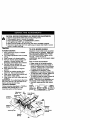
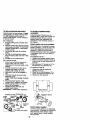
Steering Wheel
Steering Wheel
Adapter
Steering
Wheel Insed
SteeringSleeve
Seat
(1) Washer
17/32 x 1-3/16 x 12 Gauge
_(1)
(!) Shou!der
Bolt 5/16-18
Knob
Mower
(4) Retainer Springs (single loop)
(3) Retainer Springs (double loop)
Gauge Wheels
(2) Shoulder Bolts
Wheels
Q
(2) Centarlock Nuts
(2) Washers 3/8 x 3/4 x 14 Ga.
Video Cassette
Slope Sheet
D
Keys
(2) Keys
Yournew tractorhas been assembledat the factory with exceptionof those parts left
unassembledfor shippingpuqooses.To ensure safe and properoperationof your
tractorall parts and hardwareyou assemblemust be tightenedsecurely. Use the
correcttools as necessaryto insurepropertightness.
TOOLS REQUIRED
FOR ASSEMBLY
TO REMOVETRACTOR FROM
A socket wrench set will make assembly
CARTON
easier. Standard wrench sizes you need
UNPACK CARTON
are listed below.
I. Remove all accessibleloose parts and
(I) 9/16" wrench
(I) Pliers
partscartons from carton.
(1) 1/2"wrench
(!) Utility knife
2.
Cut, from top to bottom,along lineson
(1) 3/4" socket with
all four comers of carton, and lay
drive ratchet
panels flat.
(1) Tire pressure gauge
3. Remove mower and packing matedWhen dght or left hand is mentioned in
als.
this manual, it means, from your point of
4. Check for any additionallooseparts or
view, when you are in the operating
cartonsand remove.
position (seated behind the steering
wheel).
,
BEFORE REMOVING TRACTOR
FROM SKID
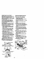
ATTACH STEERING WHEEL
1. Remove hex bolt, lock washer and
large flat washer from steedngshaft.
2, Positionfront wheels of the tractorso
they are pointingstraightforward,
3. Slidethe steedng sleeve over the
steedng shaft.
4. Positionsteedngwheel so crossbars
are horizontal(leftto dght)and slide
onto steedngwheel adapter.
5. Secure steedng wheel to steedng
shaftwith hex bolt, lockwasher and
largefiat washer previouslyremoved.
Tighten securely.
6, Snap steedng wheel insertintocenter
of steedngwheel.
7. Remove protectivematerialsfrom
tractorhood and gdll.
IMPORTANT: Check for and removeany
staplesin skid that may puncturetires
where tractoris to rolloff skid.
_Wheel
Insert
__-Hex
/Steering
Bolt
&,------Lock Washer
Large Flat
_SSteering
Wheel
/,_,dapt er
Label
INSTALL SEAT
Adjust seat before tightening adjustment
knob.
1. Remove adjustment knob and fiat
washer secudng seat to cardboard
packing and set aside for assembly of
seat to tractor.
2. Pivot seat upward and remove from
the cardboard packing. Remove the
cardboard packing and discard.
3. Place seat on seat pan and assemble
shoulder bolt. Tighten shoulder bolt
securely.
4. Assembl e adjustment knob and flat
washer loosely. Do not tighten.
5. Lower seat into operating position
and sit on seat.
6. Slide seat until a comfortable position
is reached whrch allows you to press
clutch/brake pedal all the way down.
7. Get off seat without moving its
adjusted position.
8. Raise seat and tighten adjustment
knob securely.
'i
Steerin
Seat F
_
, Flat Washer
_
//
_
.SeatPan d_(-"'--"-_'-_l ((I
r
Sleeve
\
\
HOWTO SET UPYOURTRACTOR
CHECK BATTERY
1. Lift hood to raised position.
NOTE: If this battery is put into service
after month and year indicated on label
(label located between terminals) charge
battery for minimum of one hour at 6-10
amps. (See "BATTERY" in Maintenance
section of this manual for charging
instructions).
9
Shou,derBolt ___
NOTE: You may now roll or drive your
tractor off the skid. Follow the appropriate
instruction below to remove the tractor
from the skid.
TO ROLLTRACTOR OFFSKID (See
Operation section for location and
function of controls)
1, Press lift lever plungerand raise
attachmentlift lever to its highest
position.
2. Release parkingbrake by depressing
clutch/brakepedal.
3. Place gearshiftlever in neutral(N)
position.
4. Roll tractorforwardoff skid.
TO DRIVETRACTOR
OFF SKID (See
Operation section for location and
function of controls)
_.WARNING:
Before starting read
undemtand and follow all instruct ons in
the Operation section of this manual. Be
sure tractor is in a well-ventilated area. Be
sure the area in front of tractor is clear of
other people and objects.
1. Be sure all the above assembly steps
have been completed.
2. Check engine oil level and fill fuel
tank with gasoline.
3. Sit on seat in operating position,
depress clutch/brake pedal and set
the parking brake.
4. Place gear shift lever in neutral (N)
position.
5. Press lift lever plunger and raise
attachment lift lever to its highest
position.
6. Start the engine. After angine has
started, move throttle control to idle
position.
7. Depress clutch/brake pedal into full
"BRAKE" position and hold. Move
gearshift lever to 1st gear.
8. Slowly release clutch/brake pedal and
slowly drive tractor off skid.
9. Apply brake to stop tractor, set parking
brake and place gearshift lever in
neutral position.
10.Turn ignition key to "OFF" position.
Continue with the instructions that follow.
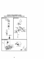
INSTALL MOWER AND DRIVE BELT
Be sure tractor is on level surface and
mower suspension arms are raised with
attachment lift control. Engage parking
brake.
1. Cut and remove ties securing antisway bar and belts. Swing anti-sway
bar to left side of mower deck.
2. Slide mower under tractor with
deflector sheild to right side of tractor.
IMPORTANT: Check belt for proper
routing in all mower pulley grooves. Install
belt into elactric clutch pulley groove.
3. Install one front link in top hole of the
R.H. front mower bracket and R.H.
front suspension bracket. Retain with
two single loop retainer springs as
shown.
4. Install second front link in L.H. front
suspension bracket only and retain
with single loop retainer spring as
shown.
5. Turn height adjustment knob counterclockwise until it stops.
6. Lower mower linkage with attachment
lift control.
7. Place the L.H. suspension arm on
inward pointing deck pin. If necessary, rock and raise front of mower to
align deck pin with the hole in
suspension arm. Retain with double
loop retainer spring with loops down
as shown.
8. Slide left side of mower back and
install the unattached front link in top
hole of the L.H. front mower bracket.
Retain with single loop retainer
spring as shown.
9. Place the R.H. suspension arm on
inward pointing deck pin. If necessary, rock and raise front of mower to
align deck pin with the hole in
suspension arm. Retain with double
loop retainer spring with loops down
as shown.
10.Connect anti-sway bar to chassis
bracket under left footrest and retain
with double loop retainer spring.
11 .Turn height adjustment knob clockwise to remove slack from mower
suspension.
12. Raise mower to highest position.
13.Assemble gauge wheels (See "TO
ADJUST GAUGE WHEELS" in the
Operation section of this manual).
10 ;
CHECK TIRE PRESSURE
The tires on your tractor were overinflated
at the factory for shipping purposes.
Correct tire pressure is important for best
cutting performance.
• Reduce tire pressure to PSI shown in
"PRODUCT SPECIFICATIONS" section
of this manual.
CHECK MOWER LEVELNESS
For best cutting results, mower should be
properly leveled. See "1"O LEVEL MOWER
HOUSING" in the Service and Adjustments
section of this manual.
CHECK FOR PROPER POSITION OF ALL
BELTS
See the.f gurus that are shown for replacing motion, mower drive, and mower blade
drive belts in the Service and Adjustments
section of this manual. Verify that the belts
are routed correctly.
CHECK BRAKE SYSTEM
After you learn how to operate your tractor,
check to see that the brake is propedy
adjusted. See "TO ADJUST BRAKE" in the
Service and Adjustments section of this
manual.
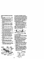
Double Loop Retainer
Front Mower
Spring(Inward
Bracket
pointingdeckpins)
Suspension
Front
Arms
Sracket
Shoulder Gauge
BoltL
Wheel
Link
Loop
Retainer Spring
3/8-16
Center
Locknut
Deflector
Shield
Retainer Spring
Retainer Springs
Anti-Sway Bar
Idler Pulley
I
ooow"n
Use Plis_ for
they are routed properly around pulleys
V CHECKLIST
and inside all belt keepers.
Before you operate and enjoy your new
/
Check wiring. See that all connections
tractor, we wish to assure that you receive
are stJllsecure and wires are properly
the best performance and satisfaction
clamped.
from this quality product.
While learning how to use your tractor,
Please review the following checklist:
pay extra attention to the following
/ All assembly instructions have been
important items:
completed.
/Engine oil is at proper level.
/ No remaining loose parts in carton.
/ Fuel tank is filled with fresh, clean,
,/Battery is properly prepared and
regular unleaded gasoline.
charged.(Minimum 1 hour at 6 amps).
/ Become familiar with all controls - their
/ Seat is adjusted comfortably and
location and function. Operate them
tightened securely.
before you start the engine.
/ All tires are properly inflated. (For
/ Be sure bi'ake system is in safe
shipping purposes, the tires were
operating condition.
overinflated at the factory).
V" Be sure mower deck is properly leveled
side-to-side/frunt-to-ruar for best cutting
results. (Tires must be properly inflated
for leveling).
,/Check mower and drive belts. Be sure 11
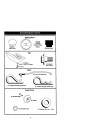
These symbolsmay appear on yourtractoror in literaturesuppliedwith the product.
Learn and understandtheir meaning.
A, =
BATTERY
CAUTION OR
WARNING
REVERSE
FORWARD
FAST
SLOW
ENG,NOON
ENG,NEOFF
OILPREBSURE
L,GHTSON
O%T_MP ]_
FUEL
CHOKE
MOWER HEIGHT
_r_RN
ATTACHMENT
CLUTCH ENGAGED
REVERSE
IG_,IITION
CLUTCH
PARKING BRAKE
LOCKED
UNLOCKED
MOWER LIFT
H L
NEUTRAL
HIGH
KEEP
AREA
LOW
CLEAR
PARKING BRAKE
SLOPE
HAZARDS
ATTACHMENT
DISENGAGED
(SEE
SAFETY
RULES
SECTION)
FREE WHEEL
(Automatic Models only)
DANGER, KEEP HANDS AND FEET AWAY
12
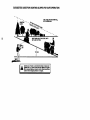
KNOWYOURTRACTOR
READ THIS OWNER'S
YOUR TRACTOR
MANUAL AND SAFETY RULES BEFORE OPERATING
Compare the illustrations with your tractor to familiarize yourself with the locations of
various controls and adjustments, Save this manual for future reference.
Ignition
Switch
PosRion
Ammeter
Switch
ThrottJe Control
Plunger
Clutch/Brake
Attachment
Lift Lever
parking Broke '
Control
Heigl"
Adjustment
Knob
e Shift Lever
Gear Shift Lever
Our tractorsconformto the safetystandardsof the AmericanNationalStandards
Institute.
ATTACHMENT CLUTCH SWITCH: Used
to engage the mower blades, or other
attachments mounted to your tractor.
LIGHT SWITCH: Turns the headlights on
and off,
THRO'I'FLE CONTROL: Used to control
engine speed.
CLUTCH/BRAKE PEDAL: Used for
declutching and braking the tractor and
starting the engine.
CHOKE CONTROL: Used when starting a
cold engine.
HEIGHT ADJUSTMENT KNOB: Used to
adjust the mower cutting height.
GEARSHIFT LEVER: Selects the speed
and direction of the tractor.
RANGESHIFT LEVER: Allows high (H)
and low (L) speed for all forward and
reverse gears,
ATTACHMENT LIFT LEVER: Used to
raise and lower the mower deck or other
attachments mounted to your tractor.
LIFT LEVER PLUNGER: Used to release
attachment lifl lever when changing its
position.
IGNITION SWITCH: Used for starting and
stopping the engine.
AMMETER: Indicates battery charging (+)
or discharging (-).
PARKING BRAKE: Locks clutch/brake
into the brake position,
13
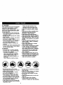
The operationof any tractorcan resultin foreign objectsthrowninto
the eyes, whichcan resultin severe eye damage. Alwayswear safety
glasses or eye shieldswhile operatingyour tractoror performingany
adjustmentsor repairs. We recommenda wide visionsafety mask
over spectaclesor standardsafety glasses.
HOWTO USEYOURTRACTOR
TO SET PARKING BRAKE
Your tractor is equipped with an operator
presence sensing switch. When engine
is running, any attempt by the operator to
leave the seat without first setting the
parking brake will shut off the engine.
1. Depress clutch/brake pedal into full
"BRAKE" position and hold.
2. Place parking brake lever in "ENGAGED" position and release
pressure from clutch'brake pedal.
Pedal should remain in "BRAKE"
position. Make sure parking brake will
hold tractor secure.
Push-In to "Disengaged Attachment Clutch
SwitchPullOut To
Chok_-_
"Braka_"_
\_)/V
Position
Clutch/Brake Pedal Hei :Adjustment
"Drive"Position
Knob
STOPPING
IMPORTANT: Leavingthe ignition switch
in any positionotherthan "OFF" will
cause the batteryto be discharged,
(dead).
NOTE: Under certainconditionswhen
tractor is standingidle with the engine
running,hot engine exhaust gases may
cause"browning" of grass. To eliminate
this possibility,alwaysstop engine when
stoppingtractoron grass areas.
_CAUTION:
Alwaysstoptractor
completely,as descnbed above, before
leavingthe operators position;to empty
grasscatcher,etc.
THROTTLE coNTRoL
Always operateengine at fullthrottle.
• Operatingengine at less than full
throttlereducesthe battery charging
rate.
• Full throttleoffersthe best bagging and
mower performance.
CHOKE CONTROL
Use choke controlwhenever you are
startinga coldengine.Do not use to start
a warm engine.
• To engage choke control,pull knob
out. Slowlypushknob in to disengage.
TO MOVE FORWARD AND BACKWARD
The directionand speed of movement is
controlledby the gearshift lever.
1. Starttractorwith clutch/brakepedal
depressed and gearshiftlever in
neutral (N) position.
2. Move gearshiftand range shift levers
to desired position.
3. Slowly release clutch/brakepedal to
start movement.
IMPORTANT: Bringtractorto a complete
stop beforeshittingor changinggears.
Failureto do so willshorten the usefullife
of yourtransaxle.
MOWER BLADES • To stop mower blades,move attachment clutch switch to "DISENGAGED"
position.
GROUND DRIVE • To stop ground drive, depress clutch/
brake pedal into full "BRAKE" position.
• Move gearshift lever to neutral (N)
position.
ENGINE • Move throttle control to slow position.
NOTE: Failure to move throttle control to
slow position and allowing engine to idle
before stopping may cause engine to
"backfire".
• Tum ignition key to "OFF" position and
remove key. Always remove key when
leaving tractor to prevent unauthorized
use,
• Never use choke to stop engine.
TO ADJUST MOWER CUTTING HEIGHT
The cutting height is controlled by turning
the height adjustment knob in desired
direction.
• Turn knob clockwise ( _ ) to raise
cutting height.
• Turn knob countemlockwise (1,-_) to
14
lower cutting height.
The cuttingheight range is approximately 1. Select desired height of cut.
2. Lower mower with attachment lift
1-1/2"to 4-1/2". The heightsare meacontrol.
sured from the groundto the blade tip with
the engine not running. These heightsare 3. Start mower blades by engaging
attachment clutch control.
approximateand may vary depending
TO STOP MOWER BLADES upon soilconditions,height of grass and
types of grass being mowed.
disengage attachment clutch control.
• The average lawn shouldbe cut to
_IbCAUTION:
Do not operate the mower
approximately2-1/2 inches duringthe
without either the entire grass catcher, on
coolseason end to over 3 inches
mowers so equipped, or the discharge
dudng hot months. For healthierand
guard in place,
better lookinglawns, mow often and
AttachmentClutch
after moderategrowth.
jAttachment
Lift
SwitchPull OutTo
• For best cuttingperformance,grass
Lever High
over 6 inchesin height shouldbe
mowed twice. Make the flintcut
relativelyhigh; the second to desired
_
Low
height,
TO ADJUST GAUGE WHEELS
Gauge wheels are properly adjusted
when they are slightly off the ground when
mower is at the desired cutting height in
operating position. Gauge wheels then
keep the deck in proper position to help
prevent scalping in most terrain conditions.
NOTE: Adjust gauge wheels with tractor
on a flat level surface.
1. Adjust mower to desired cutting height
(See "TO ADJUST MOWER CUTTING
HEIGHT" in the Operation section of
this manual).
2. With mower in desired height of cut
position, gauge wheels should be
assembled so they are slightly off the
ground. Install gauge wheel in appropriate hole with shoulder bolt, 3/8
washer, and 3/8-16 Iocknut and tighten
securely.
3. Repeat for opposite side installing
gauge wheel in same adjustment hole.
Oau Wh
. ,,
Bracket_
_(_\\ _
_
,
J
_,__
Deflector
Shield
TO OPERATE ON HILLS
_CAUTION:
Do not drive up or down
hills with slopes greater than 15 ° and do
not ddvs across any slope. Use the slope
guide provided at the back of this manual.
• Choose the slowest speed before
starting up or down hills.
• AvOid stopping or changing speed on
hills.
• If slowing is necessary, move throttle
control lever to slower position.
• II_stopping is absolutely necessary,
push clutch/brake pedal quickly to
brake position and engage parking
brake.
• Move gearshift lever to 1st gear and
range shift lever to low (L) position. Be
sure you have allowed room for tractor
to roll slightly as you restart movement.
• To restart movement, slowly release
parking brake and clutcWbrake pedal.
'• Make ell turns slowly.
TO TRANSPORT
• Raise attachment lift to highest position
with attachment lift control.
• When pushing or towin_ your tractor,
Gau3/8_,_ahe_:_i,_l
J
hh
oulder
be sure gearshift lover is in neutral (N)
position.
• Do not push or tow tractor at more than
five (5) MPH.
TO OPERATE MOWER
NOTE: To protect hood from damage
Your tractor is equipped with an operator
when transporting your tractor on a truck
presence sensing switch. Any attempt by
or a trailer, be sure hood is closed and
the operator to leave the seat with the
secured to tractor. Use an appropdate
engine running and the attachment
means of tying hood to tractor (rope, cord,
clutch engaged will shut off the engine.
15 etc.).
TOWING
CARTS
ANDOTHER
ATTACHMENTS
Towonlytheattachments
thatare
recommended by and comply with
specifications of the manufacturer of your
tractor, Use common sense when towing.
Too heavy of a load, while on a slope, is
dangerous. Tires can lose traction with
the ground and cause you to lose control
of your tractor.
BEFORE STARTINGTHE
ENGINE
CHECK ENGINE OIL LEVEL
The engine in your tractor has been
shipped, from the factory, already filled
with summer weight oil.
1. Check engine oil with tractor on'level
ground.
2. Remove oil fill cap/dipstick and wipe
clean, reinsert the dipstick and push it
all the way down into the tube, wait for
a few seconds, remove and read oil
level. If necessary, add oil until
=FULL" mark on dipstick is reached.
Do not overfill.
• For cold weather operation you should
change oil for easier starting (See "OIL
VISCOSITY CHART" in the Maintenance section of this manual).
• To change engine oil, see the Maintenance section in this manual.
ADD GASOLINE
• Fill fuel tank. Use fresh,clean regular
un eaded gasolinewith a minimumof
87 octane. (Use of leaded gasoline
will increasecarbon and Jead oxide
depositsand reducevalve life). Do not
mixoil with gasoline. Purchasefuel in
quantitiesthat can be used within30
days to assurefuel freshness.
IMPORTANT: When operatingin
temperaturesbelow32°F(0°C), use fresh,
clean winter grade gasolineto help
insuregood cold weather starting.
_,WARNING: Experienceindicatesthat
alcoholblended fuels (called gasoholor
using ethanolor methanol)can attract
moisturewhich leads to separationand
formation of acids duringstorage. Acidic
gas can damage the fuel system of an
engine while in storage. To avoidengine
problems,the fuel system shouldbe
emptiedbeforestorageof 30 days or
longer. Drain the gas tank, startthe
engine and let it run untilthe fuel lines
and carburetorare empty. Use fresh fuel
next season. See Storage Instructions
for
additionalinformation. Never use engine
or carburetorcleaner productsin the fuel
tank or permanent damage may occur.
16
_QLCAUTION: Fill to bottom of gas tank
filler neck. Do not overfill. Wipe off any
spilled oil or fuel. Do not store, spill or
use gasoline near an open flame.
TO START ENGINE
When starlingthe engine for the flint time or if
the engine has run out of fuet, it wil take extra
crankincjtime to move fuel fromthe tank to
the engine.
1. Sit on seat in operating position,
depress clutch/breke pedal and set
parking brake.
2. Place gear shift lever in neutral (N)
position.
3. Move attachment clutch to "OISENGAGED" position.
4. Move throttle control to fast position
5. Pull choke control out for a cold
engine start attempt. For a warm
engine start attempt the choke control
may not be needed.
NOTE: Before starling,read the warm and
cold startingprocedures below.
6. Insert key into ignition and turn key
clockwise to "START" position and
release key as soon as engine starts.
Do not run starter continuously for
more than fifteen seconds per minute.
If the engine does not starf after
several attempts, push choke control
in, wait a few minutes and try again. If
engine still does not start, pull the
choke control out and retry, o
WARMWEATHER STARTING (50 Fand
above)
7. When engine starts, slowly push
choke control in until the engine
begins to run smoothly. If the engine
starts to run roughly, pull the choke
control out slightly for a few seconds
and then continue to push the control
in slowly.
• The attachments and ground drive can
now be used. If the engine does not
accept the load, restart the engine and
allow it to warm up for one minute
using the choke as described above.
COLD WEATHER STARTING (50° F and
below)
7. When engine starts, slowly push
choke control in until the engine
begins to run smoothly. Continue to
push the choke control in small steps
allowing the engine to accept small
changes in speed and load, until the
choke control is fully in. If the engine
starts to run roughly, pull the choke
control out slightly for a few seconds
and then continue to push the control
in slowly. This may require an engine
warm-up periodfrom several seconds
to several minutes, dependingon the
temperature.
• The attachments can be used dudng
the engine warm-up periodand may
requirethe choke controlbe pulledout
. ht,y
; ffat a highaltitude(above3000feet)
or in coldtemperatures
(below32 F) the
carburetor
fuel mixturemay needtobe
adjustedfor bestangine performance.
See
"TO ADJUSTCARBURETOR"intheService
andAdjustments
sectionofthismanual.
MOWING TIPS
• Tire chainscannot be used when the
mower housingis attached to tractor.
• Mower shouldbe properlyleveled for
bestmowingperformance. See "TO
LEVEL MOWER HOUSING" in the
Service and Adjustmentssectionof this
manual.
• Use the runneron the right side of the
mower as a guide.The blade cuts
approximatelyan inch outsidethe
runner.
• The left hand side of mower shouldbe
used for trimming.
• Drive so that clippingsare discharged
ontothe area that hasbeen cut. Have
the cut area to the dghtof the tractor.
This willresultin a more even distribution of clippingsand more uniform
cutting.
• When mowinglarge areas, start by
tuming to the dghtso that clippingswill
dischargeaway from shrubs,fences,
driveways,etc. After one or two
rounds,mow in the oppositedirection
makingleft hand turns untilfinished.
• If grass is extremelytall, itshouldbe
mowed twice to reduce load and
possiblefire hazard from dried clippings. Make first cut relativelyhigh;the
second to the desired height.
• Do not mowgrasswhen it is wet. Wet
grass will plug mower and leave
undesirableclumps. Allow grass to dry
before mowing.
• Always operate englne at full throttle
when mowing to assure better mowing
performance and proper discharge of
material. Regulate ground speed by
selecting a low enough gear to give the
mower cutting performance as well as
the quality of cut desired.
• When operating attachments, select a
ground speed that will suit the terrain
and give best performance of the
attachment being used.
17
MAINTENANCE
SCHEDULE
__._J_j,_
AsYouCOMPLETE
Check
Tire
Pr_56ure
Check Operator
T
Presence
and
InterlOCk Systems
I1_
R CheCk
forLOO_e
Fasteners
_
ii,/7
cA Sharpen/Replace MOwer Blades
S/'4
T
Lub_caUOn
Cha_
I/'
0
CheCk Batten/Level
1_6
R
Clean
Battery and Ten_lna_
11_
CheCk
Trarl$SXle
I_
A_ust
Blade Belt(s)
AdJust Motion
Oo_lng
Engine
Clean
N
Otean ALr Screen
_ld_
i1_
_
(l_t =_:
A& Filter
I1_=
_=
Inspect Mt_flerlSpark
Arr_ter
Replace Oil Filter (If equiPtOed)
a
Clean
I_
Tension
Oil
E
k#'
t/
Tension
Ddve Belt(s)
CheCk Engine Olt Level
Change
____.,J_
f__"X_.
EngLne C_llng
I_
I1_1.=
Flne
Replace
Spark
Replace
Air Filter Paper
Replace
Fuel Filter
_z
PlUg
_
Cartr;dge
_=
V
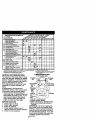
1 -Changemoleo_enwhenoperatingundersheaWto_lorlnhlgharr4mentk_mo_m_ute_.
2. Service mote ofte_ when ope ra_,g _n dirty or du0ly o¢_di_ons,
3. _ =qu_oped w_lh oil #lte_. r_langl og avery 5O hour=.
4. Reldace bkad_ mote open wh_
mowing in undy
cog.
t
5.ff_<luippedw4_adlustsb_lymrn.
$. NOt requkld
ff _quipped wH_ ma_ma_b_
7. Tight _r= Iron4 _le pivot bolt to 35 fl.4_k
Do not over_hten.
GENERAL RECOMMENDATIONS
The warrantyon thistractordoes notcover
itemsthathave been subjectedto operator
abuse or negligence.To receivefullvalue
fromthe warranty,operatormustmaintain
tractoras instructedin this manual.
Some adjustmentswill need to be made
periodicallyto properlymaintainyour
tractor.
All adjustmentsin the Serviceand
Adjustmentssectionof this manualshould
be checkedat leastonce each season.
• Once a year you shouldreplacethe
spark plug,clean or replaceair filter,and
checkbladesand beltsfor wear. A new
spark plugand clean air filterassure
properair-fuelmixture and helpyour
engine runpetter and lastlonger.
BEFORE EACH USE
'
I. Check engine oil level.
2. Check brake operation.
3. Check tire pressure.
4. Check operatorpresence and
interlocksystemsfor proper operation.
5. Check for loosefasteners.
b=tterf,
rr_xk_u_.
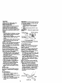
LUBRICATION CHART
® Tie Rod BallJoints
_) Spindle_
Zerk _
_Front Wheel rBesring _=
Zerk
_)Steedng _,/ I
Sector/\
Gear ,_
)-
TeethII
_)ChecW
Fluid
_--j
(_ SAE 30 or 10w30 motor oil
(_ General Purpose Grease
_) Refer to Maintenance "ENGINE" Sec_oo
@ Spray siliconelubriant(Move Bootsto
Lubricate)
IMPORTANT: Do not oil or grease the
pivot points which have special nylon
bearings. Viscous lubricants will attract
dust and dirt that will shorten the life of
the self-lubricating bearings, If you feel
they must be lubricated, use only a dry,
powdered graphite type lubricant
18sparingly.
TRACTOR
Always observe safety rules when
performing any maintenance.
BRAKE OPERATION
if tractor requires more than six (6) feet
stopping distance at high speed in
highest gear, then brake must be adjusted. (See "TO ADJUST BRAKE" in the
Service end Adjustments section of this
manual).
TIRES
• Maintain proper air pressure in all tires
(See "PRODUCT SPECIFICATIONS"
section of this manual)_
• Keep tires free of gasoline, oil, or insect
control chemicals which can harm
rubber.
• Avoid stumps, stones, deep ruts, sharp
objects and other hazards that may
cause tire damage.
NOTE: To seal tire punctures and prevent
fiat tires due to stow leaks, tire sealant
may be purchased from your local parts
dea_er. Tire sealant also prevents tim dry
rot and corrosion.
OPERATOR PRESENCE SYSTEM
Be sure operator presence and interlock
systems are working properly. If your
tractor does not function as described,
repair the problem immediately.
• The engine should not start unless the
clutch/brake pedal is fully depressed
and attechement clutch control is in the
disengaged position.
• When the engine is running, any
attempt by the operator to leave the
seat without first setting the parking
brake should shut off the engine.
• When the engine is running and the
attachment clutch is engaged, any
attempt by the operator to leave the
seat should shut off the engine.
• The attachment clutch should never
operate unless the operator is in the
seat.
BLADE CARE
For best results mower blades must be
kept sharp. Replace bent or damaged
blades.
IMPORTANT: To ensure properassembly,
center hole in blade must align withstar
on mandrel assembly.
4. Reassemblehex bolt, lock washer
and fiat Washerin exact orderas
shown.
5. Tightenboltsecurely(27-35 Ft. Lbs.
torque),
IMPORTANT: Blade bolt is grade8 heat
treated.
TrailingEdge Up
Mandrel Assembly
Blade Center f._ F_
Flat Wesher_-_'_L_)
_.
_---Hex Bolt (Grede)*_J
*A Grade 8 heat treated boltcan bd _denti_d
by _;ixlineson the bolt head.
_:
TO SHARPEN BLADE
NOTE: We do not recommend sharpening blade - but if you do, be sure the
blade is balanced.
' '
Care should be taken to keep the blade
balanced. An unbalanced blade will
cause excessive vibration and eventual
damage to mower and engine.
• The blade can be sharpened with a file
or on a gdnding wheel. Do not attempt
to sharpen while on the mower.
• To check blade balance, you will need
a 5/8" diameter steel bolt, pin, or a cone
balancer. (When using a cone balancer, fctlow the instructions supplied
with balancer.)
NOTE: Do not use a nail for balancing
blade. The lobes of the center hole may
appear to be centered, but are not.
• Slide blade on to an unthreaded
portion of the steel bolt or pin and hold
the bolt or pin parallel with the ground.
If blade is balanced, it should remain in
a horizontal position. If either end of
the blade moves downward, sharpen
the heavy end until the blade is
balanced.
BLADE REMOVAL
t.
Raise mower to highest posit_onto
allow access to blades.
2. Remove hex bctt, lock washer and flat
washer securing blade.
3. Install new or resherpened blade with
trailing edge up towards deck as
shown.
5/8" B_al_
'
Canter Hok_
19
BATTERY
Yourtractorhas a batterychargingsystem
which is sufficientfor normal usa, How_=ver,periodicchargingof the battery with
an automotivechargerwill extend its life.
• Keep battery and terminalsclean.
• Keep batteryboltstight.
• Keep small vent holesopen.
• Rechargeat 6-10 amperes for 1 hour.
• NOTE: The originalequipmentbatteryon
yourtractoris maintenancefree. Do not
attemptto open or remove caps or covers.
Addingor checkinglevel of electrolyteis
not necessary.
TO CLEAN BA'I-rERYAND TERMINALS
Corrosion and dirt on the batteryand
terminalscan cause the batteryto "leak"
power.
1. Remove terminal guard.
2. DisconnectBLACK batterycable first
then RED batterycable and remove
batteryfrom tractor.
3, Rinse the battery with plain water and
dry,
4. Clean terminalsand batterycable ends
with wire brush untilbright.
5. Coat terminalswith grease or petroleum jelly.
6. Reinstallbattery(See "REPLACING
BATTERY"in the SERVICE AND
ADJUSTMENTS sectionof this
manual),
V-BELTS
Check V-beltsfor deteriorationand wear
after 100 hoursof operationand replaceif
necessary.The belts are not adjustable.
Replace belts if they begin to slipfrom
wear.
TRANSAXLE
ENGINE
LUBRICATION
Only use high qualitydetergentoil rated
with API serviceclassificationSF-SJ,
Selectthe oil'sSAE viscositygrade
accordingto your expected operating
temperature.
COOLING
Keep transaxle free from build-up of dirt
and chaff which can restrict cooling.
CHECKTRANSAXLE
OIL LEVEL
I. Block up rear axle securely.
2. Remove left rear wheel by removing
hub bolts.
3. Remove filler plug from trensaxle. Oil
level must be even with plug threads.
If necessary, fill with SAE 30 motor oil,
API SF, SG or SH. Replace filler plug.
4. Reassemble wheel to hub.
SAE VISCOSITY
GRADES
Change the oil alter avery 50 hours of
operation or at least once a year if the
tractor is not used for 50 hours in one
year.
Check the crankcase oil level before
starting the engine and after each eight
(6) hours of operation. Tighten oil fillcap/
dipstick securely each time you check the
oil level.
TO CHANGE ENGINE OIL
Determine temperature range expected
before oil change. All oil must meet API
service classification SF-SJ.
• Be sure tractor is on level, surface.
• Oil will drain more freely when warm.
• Catch oil in a suitable container.
1. Remove oil fill cap/dipstick. Be careful
not to allow dirt to enter the engine
when changing oil. ,
2. Remove drain plug,
3. After oil has drained completely,
replace oil drain plug and tighten
securely.
4. Refill engine with oil through oil fill
dipstick tube. Pour slowly. Do not
overfill. For approximate capacity see
"PRODUCT SPECIFICATIONS"
section of this manual.
5. Use gauge on oil fill cap/dipstick for
checking level. Insert dipstick into the
tube and rest the oil fill cap on the
tube. Do not thread the cap onto the
tube when taking reading.
Keep oil
at "FULL" line on dipstick. Tighten cap
onto the tube securely when finished.
o
.-------Transaxle Filler
Plug
20
Dipstick
CLEAN
AIRSCREEN
Airscreen
mustbekeptfreeofdirtand
chafftoprevent
engine
damage
from
overheating.
Cleanwitha wirebrushor
compressed air to remove dirt and
stubbom dded gum fibers.
CLEAN AIR INTAKE/COOLING AREAS
To insure proper cooling, make sure the
grass screen, cooling fins, and other
extemal surfaces of the engine are kept
clean at all times.
Every 100 hours of operation (more often
under extremely dusty, dirty conditions),
remove the blower housing and other
cooling shrouds. Clean the cooling fins
and external surfaces as necessary.
Make sure the cooling shrouds ere
reinstalled.
NOTE: Operating the engine with a
blocked grass screen, dirty or plegged
cooling fins, and/or cooling shrouds
removed will cause engine damage due
to overheating.
AIR FILTER
Your engine will not run properly using a
dirty air filter. Clean the foam pre-clea_er
after every 25 hours of operation or every
season. Service paper Cartridge every
100 hours of operation or every season,
whichever occurs first.
Service air cleaner more often under
dusty conditions.
1. Loosen knob and remove cover.
TO SERVICE PRE-CLEANER
2. Slide foam pre-cleaner off cartridge.
3. Wash it in liquid detergent and water.
4. Squeeze it dry in a clean cloth. Allow
it to dry.
'
'
5. Saturate it in engine OiL Wrap it in
clean, absorbent cloth and squeeze to
remove excess oil.
TO SERvICE CARTRIOGE
Gartddge
Foam Prs-CIeanor-.._..A.._.\_._ti_J"
Cartridgeplate--_.......f;_._.x_
_ "_J_
ENGINE OIL RLTER
Replace the engine oil filter every season
or every other oil change if the tractor is
used more than 100 hours in one year.
MUFFLER
Inspect and replace corroded muffler and
spark arrester (if equipped) as it could
create a fire hazard and/or damage.
SPARK PLUGS
Replace spark plugs at the beginning of
each mowing season or after every 100
hours of operation, whichever occurs first.
Spark plug type and gap setting are
shown in "PRODUCT SPECIFICATIONS'_
section of this manual.
IN-LINE FUEL FILTER
The fuel filtershouldbe replacedonce ;
eachseason. If fuel filterbecomes
clogged,obstructingfuel flow to carburetot, replacementis required.
1. With engine cool, remove filter and
plug fuel line sections.
_
2. Place new fuel filterin positionin fuel
line with arrow pointingtowards
carburetor.
3. Be sure there are no fuel line leaks
and clamps are properlypositioned.
4. Immediatelywipe up any spilled
gasoline.
CI_
Clamp
• Replace a dirty, bent, or damaged
Fuel Filter_
cartddge.
CLEANING
NOTE: Do not wash the paper cartridge
• Clean engine, battery, seat, finish, etc.
or use pressurized air, as this will
of all foreign n_tter.
damage the cartridge.
• Keep finished surfaces and wheels free
6. Remove nut and cartridge plate.
of all gasoline, oil, etc.
7. Reinstall the pre-cleaner (cleaned
• Protect painted surfaces with automoand oiled) over the paper cartridge.
tive type wax.
8. Chock rubber seal for damage and
We de not recommend using a garden
proper position around stud. Replace
hose to clean your tractor unless the
if necessary.
electrical system, muffler, air filter and
9. Reassemble air cleaner, cartridge
carburetor are covered to keep water out.
plate, and nut.
Water in engine can result in a shortened
10.Reinstall air cleaner cover and secure
by tightening knob.
21 engine life,
CAUTION: BEFORE PERFORMING ANY SERVICE OR ADJUSTMENTS:
I. Depress clutch/brake pedal fully and set parking brake.
2. Place geamhift lever in neutral (N) position.
3. Place attachment clutch in =DISENGAGED" position,
4. Turn ignition key =OFF" and remove key.
5. Make sure the blades and all moving parts have completely stopped.
6. Disconnect spark plug wire from spark plug and place wire where it cannot
come in contact with plug.. _;
TO LEVEL MOWER HOUSING
Adjust the mower while tractor is parked
on level ground or driveway, Make sure
tires are properly inflated (See =PRODUCT SPECIFICATIONS" section of this
manual). If tires are over or
undednfiated, you will not propedy adjust
your mower,
SIDE-TO-SIDE ADJUSTMENT
TO REMOVE MOWER
1. Place attachment clutch in =DISENGAGED" position.
2. Turn height adjustment knob to lowest
setting.
3. Lower mower to its lowest position.
4. Remove retainer spring holding antisweybar to chassis bracket and
disengage anti-sweybar from bracket,
5. Remove retainer spdngs from
suspension arms at deck and disengage arms from deck.
6. Raise attachment lift to its highest
position.
7. Remove two retainer springs from
each front link and remove links.
8. Slide mower forward and remove belt
from eJectdc clutch pulley.
9. Slide mower out from under dght side
of tractor.
IMPORTANT: if an attachment other than
the mower deck is to be mounted on the
tractor, remove the front links.
TO INSTALL MOWER
Follow procedure described in "INSTALL
MOWER AND DRIVE BELT" in the
Assembly section of this manual.
Adjustment
Nuts
Chassis
Bracket
Lift
Links
• Raise mower to its highest position.
• Measure height from bottom edge of
mower to ground level at front corners
of mower. Distance "A" on both sides
of mower should be the same.
• If adjustment is necessary, make
adjustment on one side of mower only.
• To raise one side of mower, tighten lift
link adjustment nut on that side.
• To lower one side of mower, loosen lift
link adjustment nut on that side,
NOTE: Each full turn of adjustment nut
will change mower height about 3/16".
• Recheck measurements after adjusting,
Bottom_ _.,
_
,,/_--_ .Bottom
edgeof\ [ I_At
mower to
groundt'_'_ - _,
I / edgeof
e
mower to
"_2_/A_;round
Front Mower
Bracket
Arms
Retainer
Spring
Retainer
Spdngs
Mower
Bracket
An_-SwayBar
R_ainer
Spnngs
22
FRONT-TO-BACK ADJUSTMENT
IMPORTANT: Deck must be level side-toside. If the following front-to-back
adjustment is necessary, be sure to adjust
both front links equally so mower will stay
level side-to-side.
To obtain the best cutting results, the
mower housing should be adjusted so
the front is approximately 1/8" to 1/2"
lower than the rear when the mower is in
its highest position.
Check adjustment on right side of tractor.
Measure distance "P directly in front of
and behind the mandrel at bottom edge
of mower housing as shown.
• Before making any necessary adjustments, check that both front links are
equal in length.
• If links are not equal in length, adjust
one link to same length as other link.
• To lower front of mower housing,
loosen nut "(3" on both front links an
equal number of tums.
• When distance "P is 1/8" to 1/2" lower
at front than rear, tighten nut "H"
against trunnion on both front links.,
• To raise front of mower housing, loosen
nut =H" from trunnion on both front links.
Tighten nut "G" on both front links an
equal number of tums.
• When distance "P is 1/8" to 1/2" lower
at front than rear, tighten nut "1-1"
against trunnion on both front links.
NOTE." Each full tum of nut "(3" will
change dim, =P by approximately 3/8".
• Recheck side-to-side adjustment.
TO REPLACE MOWER DRIVE BELT
MOWER DRIVE BELT REMOVAL
1. Park tractor on a level surface.
Engage parking brake.
2. Remove screws from L.H. mandrel
cover and remove cover.
3. Roll belt over the top of L.H. mandrel
pulley.
4. Remove belt from electric clutch
pulley.
5. Remove belt from idler pulleys.
6. Remove any dirt or grass clippings
which may have accumulated around
mandrels and entire upper deck
surface.
7. Check primary idler arm and two
idlers to see that they rotate freely.
8. Be sure spring is securely hooked to
pdmary idler arm and bolt in mower
housing.
MOWER DRIVE BELT INSTALLATION
9. Install belt in both idters. Make sure
belt is in both belt keepers at the
idlers as shown.
10. Install new belt onto electdc clutch
pulley.
11.Roll belt into upper groove of L.H.
mandrel pulley.
t 2.Carefully check belt routing making
sure belt is in the grooves correctly
and inside belt keepers.
13.Reassemble L.H. mandrel cover.
_Screws
l--
Left_
Hand f_ ,_
Man_lrel_l
Cover
vW
=
• . o
Idler
Left Hand
Mandrel
andrel
BothFront LinksShouldbe Equal in Length
Mower,
Drive
Belt
Belt
Keepers
.u,
Trunmonf_
Front Links
23
Electric
T
Clutch
_ Mower
r Drive
TO REPLACE MOWER BLADE DRIVE
BELT
TO ADJUST ATTACHMENT
The electric clutch should provide years of
service. The clutch has a built-in brake that
stops the pulley within 5 seconds. Eventually, the internal brake will wear which may
cause the mower blades to not engage, or,
to not stop as required. Adjustments
should be made by your nearest Sears or
other qualified service center.
1. Make sure attachment clutch and
ignition switches are in _OFF" position.
2. Adjust the three nylon Iocknuts until
space between clutch plate and rotor
measures .012" at all three slot
locations cut in the side of brake plate.
NOTE: After installing a new electdc
clutch, run tractor at full throttle and
engage and disengage electric clutch 10
cycles to wear in clutch plate.
Park the tractor on level surface. Engage
parking brake.
1. Remove mower drive belt (See "TO
REPLACE MOWER DRIVE BELT" in
this section of this manual).
2. Remove mower (See "TO REMOVE
MOWER" in this section of this
manual).
3. Remove screws from R.H. mandrel
cover and remove cover. Unhook
spring from bolt on mower housing.
4. Carefully roll belt off R.H. mandrel
pulley.
5. Remove belt from center mandrel
pulley, idler pulley, and L.H. mandrel
pulley.
6. Remove any dirt or grass which may
have accumulated around mandrels
and entire upper deck surface.
7. Check secondary idler arm and idler
to see that they rotate freely.
8. Be sure spring is hooked in secondary
idler arm and sway-bar bracket.
9. Install new belt in lower groove of L.H.
mandrel pulley, idler pulley, and
center mandrel pulley as shown.
10. Roll belt over R.H. mandrel pulley.
Make sure belt is in all grooves
properly.
11. Reconnect spring to bolt in mower
housing and reinstall R.H. mandrel
cover.
12. Reinstall mower to tractor (See
=INSTALL MOWER AND DRIVE
BELT" in the Assembly section of this
manual).
• Rsassemb e mower ddve belt (See
"TO REPLACE MOWER DRIVE BELT"
in this section of this manual).
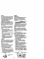
Left Hand
Mandrel
Mower
Blade
CLUTCH
.0t _ c,u,c. .atel/
0,2"
Nylon_ Slot !3)
Locknut (3)'--'-T_
_
i
._ [
_rreke
Plate
TO ADJUST BRAKE
Center" :
Mandrel
Flight'Hand
Mandrel
Cover
Yourtractor is equipped with an adjustable
brake system which is mounted on the left
side of the transaxle.
If tractor requires more than six (6) feet
stopping distance at high speed in highest
gear on a level dry concrete or paved
surface, then brake must be adjusted.
1. Depress clutcl'dbreke pedal and
engage parking brake.
2. Measure distance between brake
operating arm and nut "A"on brake rod.
3. If distance is other than 1-3/4", loosen
jam nut and tum nut =A" until distance
becomes 1-3/4". Ratightsn jam nut
against nut "A'.
4. Road test tractor for proper stopping
distance as stated above. Readjust if
necessary. If stopping distance is still
greater than six (6) feet in highest gear,
further maintenance is necessary.
Contact your nearest Sears or other
qualified service center.
_
Sway Bar
Bracket
_0_
24
Brake
With"Engaged"
Parking
Nut =A"
/
J Jam Nut
_..-------_--___._Ope
ratlng
TOREPLACE
MOTION
DRIVE
BELT
Parkthetractoronlevelsurface.Engage
parking
brake.Foreaseofservice
there
isa beltinstallation
guidedecalon
bottom
ofleftfootrest.Itisnotnecessary
to remove
mower.
BELT
REMOVAL
1. Engage
parking
brake(creates
slack
inbelt).
2. Remove
mowerdrivebelt from electric
clutch pulley only (See "TO REPLACE
MOWER DRIVE BELT" in this section
of this manual).
3. Roll motion drive belt off transaxle
pulley.
4. Roll belt off clutching idler pulleys,
then off engine pulley and front V-idler
pulley.
5. Pull belt out of all belt keepers.
BELT INSTALLATION -
TO ADJUST STEERING WHEEL
ALIGNMENT
If steeringwheel crossbarsare not
horizontal(left to right)when wheels are
positionedstraightforward, remove
steeringwheel and reassembleper
instructionsin the Assemblysectionof
this manual.
FRONT WHEEL TOE-IN ADJUSTMENT
Front wheel toe-in is required for proper
steering operation. Toe-in was set at the
factory and adjustment should not be
necessa,ry. If parts in the front axle or
steering mechanism have been replaced
or damaged, check toe-in and adjust if
necessary.
TOCHECKTOE-IN
'
1. Position front wheels straight ahead.
2. Measure distance between wheels at
front and rear of tires (d!mensiqns "A"
and "B").
,
• Front dimension "A" should be 1,/8" to
1/4" less than rear dimension "B".
TO ADJUST TOE-IN -
1. Place V part of belt into grooves on
engirte pulley and'front V-idler,
making sure to route belt inside of belt
keepers.
2. Put belt coming from V-idler above
midspan belt keeper, then onto
clutching idler pulleys as shown.
3. Make sure V part of belt engages Vidler.
4. Place belt around transaxle pulley,
beginning at top.
V part of belt should engage transaxle
pulley.
5. Place long lower section of belt
through loop in midspan belt keeper.
6. Check to be sure belt is on proper
side of all belt keepers.
7. Reinstall mower drive belt onto
electdc clutch pulley.
IMPORTANT: Check Brake Adjustment
1. Loosen jam nuts at adjustment
sleeves on tie rod.
2. Adjust tie rod until dimension =A"is
1/8" to 1/4" less than dimension "13".
3. Tighten jam nuts securely.
Adjustment Sleeves
Clutching Flat Idler
Engine
Jam Nuts
Pulley
FRONT WHEEL CAMBER
Keeper
The front wheel camber is not adjustable
on your tractor. If damage has occurred to
affect the front wheel camber, contact
your nearest Sears or other qualified
service center. •
25
TO REMOVEWHEEL FOR REPAIRS
FRONT WHEEL 1. Block up axle securely.
2. Remove axle cover, retaining ring and
washers to allow wheel removal.
3. Repair tire and reassemble.
4. Replace washers and snap retaining
ring securely In axle groove.
5. Replace axle cover.
REAR WHEEL 1. Block rear axle securely.
2. Remove five (5) hub bolts to allow
wheel removal.
3. Repair tire and reassemble. Replace
and tighten hub bolts securely.
NOTE= To seal tire punctures and prevent
flat tires due to slow leaks, tire sealant
may be purchased from your local parts
dealer. Tire sealant also prevents tire dry
rot and corrosion.
Retaining
Ring \
Washers_
_.
f_L.'_L
/\
_!,_r_//_/,,_,_l._
c
TO START ENGINE WITH AWEAK
BA'R'ERY
_3. AU1]ON: L.ead-scidbatteriesgenerate
e_plosivegases. _,eep sparks, flame and
.smokingmaterials away from batteries.
Always wear eye protectionwhen around
batteries.
If yourbattery istoo weak to startthe engine, it
shouldbe recharged. (See "BATI'ERY" in the
MAINTENANCE section of this manual).
If _jumper cables" are used for emergency
stsrtmg,followthis procedure=
IMPORTANT: Yourtractoris equippedwith a
12 voltnsgativegrounded system.The other
vehical must also be a 12 volt negative
9muP_ed system. Do not use your tractor
batteryto start othervehicels,
TO ATrACH JUMPER CABLES 1. Connect each end of the RED cable to
the POSITIVE (+) terminal of each
battery, taking care not to short
against chassis.
2. Connect one end of the BLACK cable
to the NEGATIVE (-) terminal of fully
charged battery.
3. Connect the other end of the BLACK
cable to good CHASSIS GROUND,
away from fuel tank and battery.
TO REMOVE CABLES, REVERSE ORDER 1. BLACK cable first from chassis and
then from the fully charged battery.
2. RED cable last from both batteries.
REPLACING
BATTERY
A
a4LCAUTION: Do not short battery
terminals by allowing a wrench or any
other object to contact both terminals at
the same time. Before connecting battery,
remove metal bracelets, wristwatch
bands, rings, etc.
Positive terminal must be connected first
to prevent sparking from accidental
grounding.
1. Lift hood to raised position.
2. Remove terminal guard.
3. Disconnect BLACK battery cable then
RED battery cable and carefully
remove battery from tractor.
4. Install new battery with terminals in
same position as old battery.
5. Reinstall terminal guard.
6. First connect RED battery cable to
positive (+) battery terminal with hex
bolt and keps nut as shown. Tighten
securely.
7. Connect BLACK grounding cable to
negative (-) battery terminal with
remaining hex bolt and keps nut.
Tighten securely
8. Close terminal access doom.
9. Close hood.
Terminal
Access
Ooor_
Terminal
K_S NI_/_-----.,,,,_-Iex
Bait
,._;_: .... _
_
"
_
_
J
_ ._-_1,_"
Positive
_IP_..(Red )
Guard _
I.]
26
_._Negative
_
Cable
(3able
(Black)
TO REPLACE HEADMGHT BULB
1. Raise hood.
2. Pull bulb holder out of the hole in the
backside of the grl,.
3. Replace bulb in holder and push bulb
holder securely back into the hole in
the backside ot the grill
4. Close hood.
INTERLOCKS AND RELAYS
Looseor damagedwiringmay cause your
tractorto run poorly,stoprunning,or
preventitfrom starting.
• Check widng. See electricalwiring
diagram in the Repair Parts section.
TO REPLACE FUSE
Replacewith 30 amp automotive-type
plug-infuse. The fuse holderis located
behindthe dash.
TO ADJUST ATTACHMENT LIFT
SPRING
1. While holding spring bushing with '
wrench, loosen jam nut.
• Turn adjustment belt clockwise io
extend spring and reduce lift effort for
heavier attachments.
• Turn adjustment bolt counterclockwise
for lighter attachments.
2. Retighten jam nut against spring
bushing.
IMPORTANT: Do not adjust for maximum
spdng tension when using light attachments such as a mower. Adjust lift lever
spring to aid in lifting attachment. Do not
overpower spring. When removing
attachment, always adjust spdng tension
to its lowest position.
HeadlightWire
ector
Maintenance,repair, or replacementof
the emissioncontroldevices and systems, whichare being done at the
customersexpense, may be pedormed
by any non-mad engine repair establishmentor individual.Warranty repairsmust
be performedby an authorizedengine
manufacturer'sservice outlet.
ENGINE
TO ADJUST THROTTLE CONTROL
CABLE
The throttle control has been preset at the
factory and adjustment should not be
necessary. Check adiustment as described below before loosening cable. If
adjustment is necessary, proceed as
follows:
1. With engine not running, move throttle
control lever to fast position.
2. Check that speed control lever is
against stop screw. If it is not, loosen
casing clamp screw and pull throttle
cable until lever is against screw.
Tighten clamp screw securely.
Idle Fuel Adjusting
Idle speed Adjusting
./Screw
Adjustment Bolt
Throttle
Control
AttachmentLift
Jam Nut
Spdng
TO REMOVE HOOD AND GRILL
ASSEMBLY
1. Raise hood.
2. Unsnap headlight wire connector.
3, Stand in front of tractor. Grasp hood at
sides, tilt toward engine and lift off of
tractor,
4. To replace, reverse above procedure. 27
Stop
Screw
Choke Control Cable
I'O ADJUST CHOKE CONTROL
PRELIMINARY SETTING -
]'he choke control has been preset at the
_actory and adjustment should not be
_ecessary. check adjustment as de.
scribed below before loosening cable. If
adjustment is necessary, proceed as
_ollows:
•
1. With engine not running, move choke
control (located on dash panel) to full
choke position.
2. Remove air cleaner cover, filter and
cartridge plate to expose carburetor
choke (See =AIR FILTER" in the
Customer Responsibilities section of
this manual).
3. Choke should be closed. If it is not,
loosen casing clamp screw and move
choke cable until choke is completely
closed. Tighten casing clamp screw
securely.
4. Reassemble air cleaner.
1. Be sure you have a clean air filter, and
the throttle control cable is adjusted
properly (see "TO ADJUST
THROTTLE CONTROL CABLE" in the
Service and Adjustments_section of
this manual).
2. With engine off turn idle fuel adjusting
needle in (clockwise) closing it finger
tight and then rum out (counterclockwise) 1 rum.
FINAL SETTING 1. Start engine and allow to warm for five
minutes. Make final adjustments with
engine running and shift/motion
control lever in neutral (N) position.
NOTE: The high idle is set at the factory
and cannot be adjusted.
2. Idle speed settin_o- With throttle
control lever in slow position, engine
should idle at 1200 RPM. If engine
idles too slow or fast, turn idle speed
adjusting screw in or out until correct
idle is attained.
3. Idle fuel needle setting - With throttle
control lever in slow position, turn idle
fuel adjusting needle in (clockwise)
until engine speed decreases and
then turn out (counterclockwise)
approximately 3/4 turn to obtain the
best low speed performance.
4. Recheck idle speed. Readjust if'
necessary.
ACCELERATION TEST 5. Move throttle control lever from slow to
fast position. If engine hesitates or
dies, turn idle fuel adjusting needle
out (counterclockwise) 1/8 turn.
Repeat test and continue to adjust, if
necessary, until engine accelerates
smoothly.
High speed stop is factory adjusted. Do
not adjust-damage may result.
IMPORTANT: Never tamper with the
engine governor, which is factory set for
proper engine speed. Overspeeding the
engine above the factory high speed
setting can be dangerous. If you think the
engine-govsmed high speed needs
adjusting, contact your nearest Sears or
other qualified service center, which has
proper equipment and experience to
make any necessary adjustments.
Closed For Full-_=
Choke
TO ADJUST CARBURETOR
The carburetor has been present at the
factory and adjustment should not be
necessary. However, minor adjustment
may be required to compensate for
differences in fuel, temperature, altitude
or load. If the carburetor does need
adjustment, proceed as follows:
In general, turning the adjusting needles
in (clockwise) decreases the supply of
fuel to the engine giving a leaner fueVair
mixture. Turning the adjusting needles out
(countemlockwise) increases the supply
of fuel to the engine giving a richer fueV
air mixture.
IMPORTANT:" Damage to the needles
and the seats in carburetor may result if
screw is turned in too tight.
28
Immediately prepare your tractor for
storage at the end of the season or if the
tractor will not be used for 30 days or
more.
_, CAUTIOI_h Neverstore the tractor
with gasoline in the tank inside a building
where fumes may reach an open flame or
spark. Allow the engine to cool before
storing in any enclosure.
TRACTOR
Remove mower from tractor for winter
storage. When mower is to be stored for a
period of time, clean it thoroughly, remove
all dirt, grease, leaves, etc. Store in a
clean, dry area.
t. Clean entire tractor (See "CLEANING"
in the Maintenance section of this
manual).
2. Inspect and replace belts, if necessary
(See belt replacement instructions in
the Service and Adjustments section of
this manual).
3. Lubricate as shown in the Maintenance section of this manual.
4. Be sure that all nuts, bolts and screws
are securely fastened. Inspect moving
parts for damage, breakage and wear.
Replace if necessary.
5. Touch up all rusted or chipped paint
surfaces; sand lightly before painting.
BAI-FERY
• Fully charge the battery for storage.
• After a period of time in storage, battery
may require recharging.
• To help prevent corrosion and power
leakage dudng long periods of storage,
battery cables should be disconnected
and battery cleaned thoroughly (see
"TO CLEAN BA'I-I'ERY AND TERMINALS" in the Maintenance section of
this manual).
• After cleaning, leave cables disconnected and place cables where they
cannot come in contact with battery
terminals.
• If battery is removed from tractor for
storage, do not store battery directly on
concrete or damp Surfaces.
experiance indicates that alcohol blended
fuels (called gasohol or using ethanol or
methanol) can attract moisture which leads
to separation and formation of acids during
storage. Acidic gas can damage the fuel
system of and engine while in storage.
1. Drain the fuel tank.
2. Start the engine and let it run until the
fuel lines and carburetor are empty.
• Never use engine or carburetor cleaner
products in the fuel tank or permanent
damage may occur.
• Use fresh fuel next season.
NOTE: Fuel stabilizer is an acceptable
alternative in minimizing the formation of
fuel gum deposits during storage. Add
stabilizer to gasoline in fuel tank or storage
container. Always follow the mix ratio
round on stabilizer container. Run engine
at least 10 minutes after adding stabilizer
to allow the stabilizer to reach the carburetor. Do not drain the gas tank and carburetor if using fuel stabilizer.
ENGINEOIL
Drain oil (with engine warm) and replace
with clean engine oil. (See "ENGINE" in
the Maintenancesectionof this manual).
CYLINDER(S)
1. Remove spark plug(s).
2. Pour one ounce of oil through spark
plug hole(s) into cylinder(s).
3. Turn ignition key to =START" position
for a few seconds to distribute oil.
4. Replace with new spark plug(s).
OTHER
• Do not store gasoline from one season
to another.
• Replace your gasoline can if your can
starts to rust, Rust and/or dirt in your
gasoline will cause problems.
• If possible, store your tractor indoors and
cover it to give protection from dust and
dirt.
• Cover your tractor with a suitable
protective cover that does not retain
moisture. Do not use plastic. Plastic
cannot breathe which allows condensation to form and will cause your tractor to
rust.
IMPORTANT:
Never cover tractor while
engine and exhaust areas are still warm.
ENGINE
FUEL SYSTEM
IMPORTANT: It is important to prevent
gum depositas from forming in essential
fuel system parts such as carburetor, fuel
hose, or tank during storage. Also,
29
TROUBLESHOOTING CHART
PROBLEM
' Will not start
Hard to start
CAUSE
CORRECTION
1. Out of fuel.
2. Engine not =CHOKED"
properly.
3. Engine flooded.
1. Fill fuel tank.
2. See "TO START ENGINE"
in Operation section.
3. Wait several minutes
before attempting to start.
4. Replace spark plug.
. Bad
spark
plug.
Dirtyair
filter.
5. Clean/replace air filter.
6. Dirtyfuel filter.
6. Replace fuel filter.
7 Water in fuel.
7. Drain fuel tank and
carburetor, refill tank with
fresh gasoline and replace
fuel filter.
8. Loose or damaged wiring.
8. Check all widng.
9. Carburetor out of adjustment, 9. See "To Adjust Carburetor"
in Service Adjustments
section.
10.Contect a Sears or other
10. Engine valvesout of
adjustment.
qualified service center.
1. Dirtyair filter.
2. Bad spark plug.
3. Weak or dead battery.
4.
5.
1. Clean/replace air filter.
2. Replace spark plug.
3. Recharge or replace
battery.
Dirty fuel filter.
;4. Replace fuel filter.
i5. Drain fuel tank and refill
Stale or dirty fuel.
with fresh gasoline.
Loose or damaged wiring. 6. Check all wiring.
Carburetorout of adjustment 7. See "To Adjust Carburetor"
in Service Adjustments
section.
B. Contact a Sears or other
Engine valves out of
adjustment.
qualified service center.
i
6.
7.
8.
i
Engine will not
turn over
1, Clutch/brake pedal not
depressed.
2. Attachment clutch is
engaged.
3. Weak or dead battery.
8.
Faulty so!enoid or starter.
9.
Faulty operator presence
switch(as).
3. Recharge or replace .
ba_ttery.
4. ReplaCe fuse.
5. Clean battery terminals.
6. Check all wiring,
7. Check/replace ignition
switch.
B. Check/replece solenoid or
starter.
9. Contact a Sears or other
qualified service center.
1.
2.
3.
4.
Weak or dead battery.
Corroded battery terminals.
Loose or damaged wiring.
Faulty solenoid or starter.
1.
2.
3.
4.
4. Blown fuse.
5. Corroded battery terminals.
6. Loose or damaged wiring.
7. Faulty ignition switch.
Engine clicks but
will not start
1. Depress clutch/brake
pedal.
2. Disengage attachment
clutch.
30
Recharge or replace battery
Clean battery terminals.
Check all wiring.
Check/replace solenoid or
starter.
TROUBLESHOOTING
PROBLEM
Loss of power
CHART
CAUSE
CORREC_ON
1. Cutting too much grass/too
fast.
2. Throttle in "CHOKE"
position.
3. Build-up of grass, leaves
and trash under mower.
4..Dirty air filter.
5. Low oil level/dirty oil.
6. Faulty spark plug.
1. Set in =Higher Cut" position/
reduce speed.
2. Adjust throttle control.
7. Dirty fuel filter.
8. Stale or dirty fuel.
7. Replacefuel filter.
8. Drain fuel tank and refillwith
9. Water in fuel.
9. Drain fuel tank and carbura
3. Clean undersideof mower
housing.
4. Clean/replace air filter.
5. Check oil level/changeoil.
6. Clean and regap or change
spark plug.
fresh gasoline.
tor, refilltank with fresh
gasolineand replace fuel
filter.
10. Spark plug wire loose.
10.Connect and tighten spark
plug wire.
11.Dirty engine air screen/fins. 11.Clean engine air screen/fins.
12.Dirty/cloggedmuffler.
12.Clean/replace muffler.
13.Loose or damaged widng. 13.Check all wiring.
14.Carburetorout of
14.See "To AdjustCarburetor"
adjustment.
in Service Adjustments
section.
15.Engine valvesout of
15.Contact a Sears or other
adjustment.
qualifiedservice center.
Exoeeeive
vibration
1. Worn, bent or looseblade.
2. Bent blade mandrel.
3. Loose/damagedpart(s).
1. Replace blade.
Tighten blade bolt.
2. Replace blade mandrel.
3. Tightenloose part(s).
Replace damaged parts.
Enginecontinuss
to run
when operator
leaves seat with
with attaohment
olutoh engaged
1. Faultyoperator-safety
presencecontrolsystem.
Poor cut - uneven
1. Worn, bent or loose blade. !1.
2. Mower deck not level,
3. Buildupof grass, leaves,
and trash under mower.
4. Bent blade mandrel.
5. Clogged mower deck vent
holesfrom buildupof
grass, leaves, and trash
around mandrels.
31
1. Check wiring,switches and
connections.If not
contacta Sears or other
qualifiedservice center.
Replace blade, Tighten
! 2, blade
bolt,
Level mower
deck.
3. Clean underside of mower
housing.
4. Replace blade mandrel.
5. Clean around mandrels to
open vent holes.
TROUBLESHOOTING
PROBLEM
Mower blades will
not rotate
CHART
CAUSE
CORRECTION
1. Obstruction in clutch
mechanism,
2. Worn/damaged mower
drive belt.
3. Frozen idler pulley.
4, Frozen blade mandrel.
Poor grass
discharge
1. Remove obstruction.
2. Replace mower drive belt.
3, Replace idler pulley.
4. Replace blade mandrel,
1. Engine speed too slow.
1. Place throttle control in
=FAST" position.
2. Travelspeed too fast.
2. Shift to slower speed.
3. Wet grass.
3. Allow grass to dry before
mowing.
4. Mower deck not level.
4. Level mower deck.
5. Low/uneven tire air
5. Check tires for proper air
pressure.
pressure.
6. Wom, bent or loose blade.
6. Replece/sharpen
blade.
Tighten blade bolt.
7. Buildup of grass, leaves
7. Clean underside of mower
and trash under mower.
housing.
8. Mower ddve belt worn.
8. Replace mower ddve belt.
9. Blades improperly installed. 9. Reinstall blades sharp edge
down.
lO.Improper blades used.
10.Replace with blades listed
in this manual.
11.Cloggedmower deck vent
11,Clean around mandrels to
holesfrom buildupof grass,
open vent holes.
leaves, and trash around
mandrels.
IHeadlight(s) not
working
(if so equipped)
1. Switch is "OFF".
2. Bulb(s) burned out.
3. Faultylight switch.
4. Loose or damaged wiring.
5. Blown fuse.
BaRerywillnot
charge
1. Bad battery cell(s).
2. Poor cable connections.
3. Faulty regulator
(if so equipped).
4. Faulty alternator.
Engine "backfires'
when turning
engine "OFF"
1.
2.
3.
4.
Turn switch "ON'.
Replace bulb(s).
Check/replace light switch.
Check wiring and connections.
5, Replace fuse.
1. Replace battery.
2. Check/clean all connections.
3. Replace regulator.
! 4. Replace alternator.
1. Enginethrottlecontrolnot
set at =SLOW"position
for 30 secondsbefore
stopping engine.
32
1. Move throttle control to
"SLOW" position and allow
to idle for 30 seconds before
stopping engine.
TRACTOR -- MODEL NUMBER 917.272953
SCHEMATIC
BATTERY
Rr_
SOLENOID
r .....
I
i
RE_
AMMETER
(OPTIONAL)
i
I
=
C
G
,uw
I
L
l__l
IBS
q
_
:
3
_NIT]OP,
;WITCH
|
•
l
"
PTO((_S-E_'GA-GED)
b
D ,
i
L .......
SEAT SWITCH
L_
_
_
j
_
,
,
185
86,
I_
-_
', F',_-_
_q
OPERATOR
_
RELAY #1
RELAY #1
(_J
J.;,_
(NOT OCCUPIED)
i
.u°
,,
_K
L,NE:
=
SPARK
_.UaS
I_ .......
I
FUEL SHUT-OFF
A
PTO SWITCH
IGNITION
OFF
ON
SWITCH
HEADLIGHTS
CeG, B+H
C÷F,B+E_A+D
RELAY
GFC
WIRING iNSULATED
CLIPS
NOTE: IF WIRING INSULATED
CLIPS WERE REMOVED
FOR
SERVICING
OF UNIT, THEY
SHOULD BE REPLACED
TO
PROPERLY SECURE YOUR
WIRING.
REMOVABLE
CONNECTIONS
.
NON-REMOVABLE
CONNECTIONS
H
B
CA
33
•
STARTER
........
e_ee_
I
--
,
I
--
,--1---,
aRe_t
/
f__
r .......
SL,_C
K
.I
I
,
,""_ O-4-----t _
m
]
i H'
....
II
ELECTRICAL
TRACTOR -- MODEL NUMBER 917.272953
24
33
t
iI
eI
iI
34
TRACTOR -- MODEL NUMBER 917.272953
ELECTRICAL
KEY
NO.
PART
NO.
DESCRIPTION
1
2
8
10
11
12
16
21
22
24
25
26
27
28
29
30
33
40
41
42
43
45
50
52
79
81
144927
74760412
7603J
145211
150109
145769
153664
166184
4152J
4014J
146686
1(;6824X
73510400
170697
160784
175566
140403
17(_38
177"20408
131563
175141
122822X
174652
141940
163996
109748X
Battery
Bolt Hex Head 1/4-20 x 3/4
Tray, BatterJ
Bblt 1/4-20 x 7.5 2]nc
H01d down Battery Dash Mount
Nut Push Nylon 1/4"
Switch InterlOCk push-In
Harness Socket Light W/4152J
Bulb Light
Cable, Battery
Cable, Battery
Fu6e
Nut Keps He:< 1/4-20 Unc
Cable, Ground
Switch, Plunger
Swttch, Ign
Key, IgnlUon
Harness Ign.
Screw 1/4-20 x 1/2
Cover, Termlnal
Solenoid
Ammeter
Switch, PTO
Protection Wire Loop
Bulbholder Asm. Incandescent
Reley Asm,
NOTE: All component dimensions given in U,S. Inches
1 inch = 25.4 mm
35
TRACTOR -- MODEL NUMBER 917.272953
CHASSIS AND ENCLOSURES
36
TRACTOR -- MODEL NUMBER 917.272953
CHASSIS AND ENCLOSURES
KEY
NO.
PART
NO,
DESCRIPTION
1
2
4
5
6
7
8
14
15
16
17
18
19
20
21
23
24
28
30
31
3_
33
34
35
36
37
39
40
42
43
44
45
47
175465
140506
73680700
163976X426
157882
17720408
145166
161_23X5O8
160568
121794X
17060612
160564X558
19131312
$11[To23710
STD541437
17060616
145243X558
145244X558
145651X014
161419
161327
161326
142131
19111116
74780512
167285X558
152728
156111
72140608
135O_9
136940
154913
17490606
Ralt,Frame RH
Drawbar, Gt
Nut, Crown_ock Hex 7/16-14UNC
Dash YTGT 2 Cyl
Dssh, Lower Vgt C_e P_ece
Screw, Thd Cut 1/4-20 x 1/2
Support, Battery
Hood Asrn., pot Stealth YTGT
Ler_s Asm Head4_ht Bar
Cover, Access
Screw
Gdlle
Washer 13/32x13/16x12 Ga.
Bolt, Fin Hex 3/6.16 x 1
NutCrownlock
:3/8-16Unc
Screw 3/6.16 xl.5
Footrest, RH
Footrest, LH
Saddle, Slkscr Vg!t
Brace, Supt 1-pcVGT Strg
Bracket, Pivot Chassis I.h
Bracket, Pivot ChaSSiS Rh
Bracket, Engine Support Rear
Washer 11/32x11/16x16 Ga.
Bo;t, Fkl Hex 5/16.18 x 3/4
Fender
Bracket, Axle Front
Bracket, Support Axle/Engine
Bolt, Carriage 3/_-16 x 1
Bracket, Spnsn Front Lh
BrackeL SwIsn Front Rh
Bracket Asm, Susp Chassis Rh
Screw Thdrol. 3/8-16 x 1/2
KEY
NO.
5O
52
56
58
5O
63
67
68
7O
84
85
86
88
9O
91
I06
122
130
137
139
140
141
142
144
145
147
148
150
151
PART
NO.
DESCRIPTION
152728
BTD541431
154914
175315
17060620
19131614
156973
1749(Too6
137159
142992
144911
74760716
STD551143
ST[To51237
175464
138776
161464
164863
74780716
171873
163806
163805
161897
161900
19131414
162967
164655
161237
17060512
Bracket, Chasals Front
Nut, CrOWotock 5/16-18 Unc
Bracket Asm., Susp Chassis Lh
Bracket Asm., Fender
Screw 3/6.16 x 1-1/4
Washer 13/32 x 1 x 14 Ga.
Guide, Bell Gear Drive
Screw Thdrol. 5/16-18 x 1/2
Gu_e, _t Mkl Span
Stop, Over Center Mower
Bracket, Support Transaxle
Bolt Fin Hex 7/16.14 UNC x 1
We_:_er, Lock H W t-UctSpr 7/16
Washe_, Lock External Tooth 3/8
RUIl, Frame Lh
Screw, Thdrol Hex Head Zinc Mwr
Screw Hex Wshd 6.18 x 7/6
Screw HWHD Hi-Lo #13-16 x 3/4
8(_t Fin Hex 7/16-14 xl Gr, 5
Buit Shoulder 5/1 6.18 TT
MagnetY'rGT
Striker Plate YTQT
Bracket Dash Rh
Bracket Dash Lh
Washer Flat 13/32x7/8x7 Ga.
FaStener Nut Pal
Extrusion Bumper
Duct Heat Hood
Screw 5/16-18 x 3/4
NOTE: AllcomponentdmenslonsgivenIn U.S.inches
1 Inch= 25A mm
37
TRACTOR - - MODEL NUMBER 917.272953
GROUND DRIVE
47
48
54
66
\
7
4
69
3
GROUND DRIVE
KEY PART
NO. NO.
1
3
4
5
6
7
8
9
10
11
12
13
14
15
16
17
18
19
21
22
23
24
25
26
27
9658M1
7563R
17_
ST[To41437
ST[To61210
149176
12000034
140080
142509
136927
73750800
139419
138901
STD5510_7
143012
126909X
137104
136926
2'3260412
633A109
106932X
136925
136923
137552
1749(_28
28
29
30
34
35
36
73350600
137213
19131616
71673
137648
149412
TRACTOR - - MODEL NUMBER 917.272953
DESCRIPTION
Key, Woodruff
Washer, Thrust, Axle
Screw Tildrdl 5/I 6-18 x 3/4
Nut, Crownlock 3/8-16
Pin, Cotter
Wheel, Hub Assembly
Klip, Ring
Boft, Hub
Disc, Brake
Yoke, Brake DLsc
Nutlock 1/2-20 Unf
Washer, Special
Bushing
Washer 13/22x13/16 x 16 Ga.
Set, Screw 1/4-28 x 3/4
Swing
Lever, Brake
Cam, Brake Disc
Screw, Flat Head 1/4-28 x 3/4
Gearshift, Lever Assembly
Knob
Support, Puck Brake
Puck, Brake Top
Spring, Retum
Screw, Hex Wsh Thd.
5/16-18 x 1-3/4
Nut, Hex Jam 3/8-16
Brake, Red
Washer 13/32 x 1 x 16 Ga.
Cap, Plunger
Rod, Parking Brake
Spring, Ddve Ground
KEY PART
NO. NO,
DESCRIPTION
37
38
39
40
41
42
46
47
48
50
51
52
53
54
55
56
57
59
60
61
62
63
64
66
66
67
68
69
117
Washer 25/32 x1-1/4 x 16 Ga.
Nyliner
Screw, Rn. #10.24 x 1
Actuator, intshock Switch
Locknut #10-24
Cover, Pedal
Retainer, Spring
Clutch Rod
Bolt, Con'. 3/8-16 x 1-1/2 Gr. 5
Pulley, Idler, Rat
Nut, Crow.lock 3/8-16 UNC
Pulley. Idler, Grooved
Washer, Hardened
Clutch, Arm Assembly
Bearing, Idler
V-Belt
Bracket, Shift Rod, Hi-Lo
Shift Rod, HI-Lo
Spring Clip, Connecting Unk
Pulley, Transaxle
Washer, Lock 7/16
Bolt, Rn Hex 7/16-14 x 1-1/4
Shaft, Clutch/Brake pedal
Bolt, Shoulder
Washer, Hardened
Washer, Rat
Pin, Roll
Hub, Cover
Nut. Lock Fig. 3/8-16 UOC
121749X
150035
74321016
5304J
73931(XX}
8883R
145170
138_28
72110612
131494
ST[To41437
139123
207J
161590
105706X
137153
141756
122253X
12:_o8X
137524
STD551143
74760720
154752
67609
14(_96
19131312
514.'3_
1363_7
73900600
NOTE: All component dimensions given in U.S. inches
1 inch = 25.4 mm
39
TRACTOR
-- MODELNUMBER
917.272953
STEERING
ASSEMBLY
40
TRACTOR - - MODEL NUMBER 917.272953
STEERING ASSEMBLY
KEY PART
NO. NO.
DESCRIPTION
1
2
3
4
5
6
7
8
9
10
11
12
13
14
15
16
17
18
19
2O
21
22
23
25
26
27
28
29
3O
31
32
33
34
35
36
37
38
39
4O
41
42
45
Wheel, Steedng
Axle Asm., Front
Fitting, Grease
Splndie Asm, LH
Sgindie Asm,, RH
Beadng, Race Thrust Herpan
Washer 25/3,?.x 1-5/B x 16 Ga.
Ring, Kllp #T5304-75
Cap, Spindle
Bolt, Rn Hex 5/8-11 x 2-3/4
Spacer Bearing Axle Front
Nut, Lock Range 5_-11 Unc
Washer 25/32 x 1-1/4 x 16 Ga.
Washer, Lock Hvy Hlcl Spr 3/8
Nut, Lock Center 3/8-24 UNF
Shaft Asm., Steering
Rod Asm., Tie Ball J Ball Vgt (Inc. Key No, 36-4O)
Dragllnk, Ball Joint Solid Vgt
Support Asm., Steering Vgt
Boot, Steering
Adapter, Wheoi Steering
Bush)rig, Strg. BIk
Screw
Boit, FinHex 3/8-16xl
Gr. 5
Cap, Wheel Steering
Bearing, Col. Skg.
Screw 3/8.16 x 5/4
Bearing, Range
Ring, XIIp Truarc #5304-75
Buching, Nyllner Snap
Washer 11/32 x lx 10Ga.
Washer, Lock Hvy Hlcl Spr 5/16
Boit, Fin Hex Hd 5/16-18 x 3/4
Gear, Sector Steering
Tie Rod
Jam NUt RH Thread
Joint Asm, Ball RH Thread
Jam Nut LH Thread
Joint Asm. Ball LH Thread
Bracket Switch Intertock VGT 97
Screw Thdrol 5/16-18 x 1/2 Tyt
Washer 13/32 x 2-3/8 x 12 Ga.
139768
137094
6855M
161849
161848
6266H
121748X
12000(_o9
121232X
74781044
136518
73901000
121749X
S'i_551137
STD541537
14510_
137347
137155
156011
172020
100711L
155105
152927
STD523710
139769
3366R
17000612
104239X
12000(_9
138136
19111610
S'rD551131
74780512
138(_9
137156
73360600
109850X
73700600
10_51X
155246
17490508
19133812
NOTE: All component dimensions given in U.S. Inches
1 inch = 25.4 mm
41
TRACTOR -- MODEL NUMBER 917.272953
ENGINE
21_20
18
15
29
\
39
J SPARK
KEY PART
NO. NO.
1
......
2
5
161063
13200Q00
7
8
9
10
11
12
15
16
17
18
19
151396
121361X
150828
105432X
170056
143996
151346
10g_27X
1060e2X
14O527
13290300
20
21
164O67
164863
22
24
25
26
27
164415
$11To51237
7392O6OO
3645J
139277
DESCRIPTION
Engine(See Breakdown
KohlerModelNo. CV6757,5549
MufflerSide
EtbowSTD 90 Degree 348- 18
NPT
MufflerAsm Guard
PulleyV-Idler
KeeperAsm, Belt Engine
Bud_ing
Clutch Electric
PulleyEngineVGT ElectClth
Tank FuelRear 3.50 Yt/Gt 96
Pad Spacer
Pad Spacer
Cap Asm FuelW/Gauge
PlugOilDrain(OrderFrom
EngineManufacturer)
ControlThroltle
ScrewHwhdHFLo
#13-16 x 3/4
ControlChoke
Washer ExtTooth 3/8
NutKep_ 3/8 - 24 UNF
Bushing
StemTankFue_
KEY
NO.
PART
NO.
28
29
35
37
38
39
40
41
7834R
132920
I001(To00
123487X
1_
17490636
17490664
126197)(
42
43
S'rD_51143
173937
45
47
48
51
55
65
69
74
76
80
73510400
142040
19132007
161231
13_80_36
19131614
24-041-02
162295
17000612
M73030800
ARRESTER
KIT I
DESCRIPTION
Fue_Une
Spark Attester Kft
Washer Sl_lt
ClampHose
Screw 3/8 - 16 x 1-1/4
Screw TT 3/8-16 x 2-1/4 UNC
Screw "IT 3/8-16 x 4 UNC
Washer 1-1/20D X 15/32 ID
X .250
Washer Lock 7/16
Bo_t Hex 7116 - 20 X 4 - 1/4
Ga5-1.5
Nut Kepe H 1/4-20 UNC
Spacer Engine
Washer13/32x1-114x7Ga,
Manifold Pipe VGT
Nipple Pipe 4-1/2
Washer 13/32 x 1 x 14
Gasket
Elbow Street Brass
Screw H Thdrol 3/8-16 x 3/4
Nut Flange M8-1,25
NOTE: All componentdimensionsgiven In U,S,
thchesl inch: 25.4 mm
42
TRACTOR - - MODEL NUMBER 917.272953
SEAT ASSEMBLY
KEY
NO.
PART
NO.
1
2
3
4
5
6
7
8
10
12
13
14
140123
14(T051
140675
127018X
145OO6
STD541437
124181X
171877
155925
121246X
121248X
72060412
DESCRIPTION
Seat
Bracket, Pivot Seat
Sltap, Fe_lder
Bolt, Shoulder 5/16-18 x ,62
Clip, Push In, Hinged
Nut, Crownlock 3/8-16 Unc
Spdng, Seat Cpmn
Bolt 5/16-18Uncx 5/4 w/Sems
Pan, Seat
Bracket, Mounting Switch
Bushing, Snap
Bolt, Carriage 1/4-20 X 1-1/2
KEY
NO.
PART
NO.
DESCRIPTION
15
16
17
18
19
20
21
22
134300
121250X
123976X
19171912
166369
124238X
171852
STD541431
Spacer, Split
Spring, Cpmn
Nut, Lock 1/4 Lge Flg Gr. 5
Washer 17/32xl .3/16x12 Ga.
Knob, Seat
Cap, Spdng Seat
Bolt, Shoulder 5/16-18
Nut, Crownlock 5/16-18Unc
NOTE: All component dimensions given in U.S. Jnch_
1 itch : 25.4 mm
43
TRACTOR -- MODEL NUMBER 917.272953
DECALS
2
6
15
3
10
8
19
1
12
1
16
17
NO.
1
2
3
4
5
PARt"
NO.
172507
164085
1717(_
171703
149516
6
7
8
9
10
11
12
13
133644
16_210
171765
163204
156439
490oj
146047
133179
KEY
NO.
14
15
16
17
19
23
--
DESCRIPTION
Decal,Dash Panel
Decal,Dash
Decal,Hood,Craftsman,RH
Decal,Hood,Craftsman,LH
Decal,BatteryDNGR/PSN
ENG Asm
Decal,Maintenance
Decal,Fender
DecalSD, PNLGTSRS
Decal,Fender,Craftsman
Decal,FendsrDanger
Decal,Clutch/Brake
Decal,V-Bait Ddve Schematfc
Decal, B_owerHoualng
WHEELS & TIRES
0
PARr
NO.
160397
171811
177_29
1776_8
138047
10620P.X
138311
----
DESCRIPTION
Decal,V-Belt Schematic
Decal,Repl Pads
Decal, Engine
Decal,EnglneKHLR Fan
Decal, Battery
Reftector,Tallllgt_t
Decal, HandleLft Halght
Adjust(Uft Hanale)
157199X428 Pad, Footrest
177619
Manual,Owners (Eng)
177620
Manual,Owners (Span)
KEY
NO.
1
2
3
11
4
PART
NO.
59192
65139
106228X427
106277X427
8134H
DESCRIPTION
Cap, Valve, Tire
Stem, Valve
Rim Assembly, Front
Rim Assemb_, Rear
Tube, Front (Service Item
10
5
9
6
7154J
I0_30X
140183
278H
Tube, Rear (Service Item Only)
Tim, Front
Tire, Rear
Rtting, Grease (Front Wheal
12
7
6856M
9040H
8
--
104757X428
144334
Only)
Only)
Fitting, Grease
Beadng, Flange (Front Wheel
Only)
Cap, Axle (Front Wheel only)
Sealant, Tire (10 oz. Tube)
NOTE: A, cornponant dimensions given in U.S. Inches
1 inch = 25.4 mm
44
TRACTOR - - MODEL NUMBER 917.272953
LIFT ASSEMBLY
40
39 73
34
7
7
31
9
10
39
!'\\
!
I
I
\
13
12
16
23
22
12
13
15
20
KEY
NO.
1
2
3
4
5
6
7
8
9
10
11
12
13
14
15
16
17
18
19
20
21
22
23
PART
NO.
121006X
159187
159189
120_
19292016
71110_24
125631X
1_J65X
122364X
28"/6H
146704
163552
139868
16_5
S'rD541437
674A247
STD541237
143363
STD551037
5328J
STD52710
127218
STD624006
19
KEY PART
NO. NO.
DESCRIPTION
Rod Asm., Lever
Shaft Asrn., Lift Vgt
Lever Asm., Lift Rh
E-RingTruarc#5133-87
Was_er 29/32 x 1-1/4 x 16 Ge.
Bolt, Rn Hex 3/6.16 x 1-1/2
Grip, Handle Rutod
Button, Plunger
Plunger, Button
Spdng 2-1/8"
Link Lift
Retainer, Spdng
Arm, Suspension Vgt
24
25
26
29
30
31
32
33
34
35
38
39
40
41
42
43
70
72
73
Bear_g
Nut, Crownlock 3/8-16 Uric
Spring Asm., Assist Lift
Nut, Hex Jam 3/8-16 Unc
Bracket, Spring Assist
Washer 13/32 x 13/16 x 16 Ga.
Bolt, Adjust Spdng Assist
Bolt, Fin Hex 3/8-16x 1
Link, Front
Retainer, Spring
73350800
130171
7368_600
150233
110807X
19131016
137150
ST056_07
137167
138_57
155097
123935X
17060516
73540600
19112410
123_Q4X
145212
110452
73350600
18
DESCRIPTION
Nut, Jam Hex 1/2-13 Uric
Tnmr/on
Nut, Crownlock 1/2-13 Uric
Trunnion, Infln Height
NUt, Special
Washer 13/82 x 5/8 x 16 Ga.
Spring, Compresalon Inf Hgt
I_n, Cofter 3/32xl/2
Rod, AdJ Lift
Knob, Inf 3/8-16 Uric
Pointer, Height Indicator
Plug. Hole
Screw 5/16-18 x 1
Nut, Ctownlock 3/6.24
Washer 11/32 x 1-1/2 x 10 Ga.
Scale, Indicator Height
Nut Hex Range Lock
Nut Push Phos & Oil
Nut Hex Jam 3/8-16
NOTE: ANcomponent dlme_'_ons given In U.S. Inches
1 Inch = 25.4 mm
45
TRACTOR -- MODEL NUMBER 917.272953
MOWER DECK
46
46
49
41
47
I
117
22
21
117
46
TRACTOR - - MOOEL NUMBER 917.272953
MOWER DECK
KEY
NO.
1
3
5
6
8
9
10
11
13
14
15
16
18
19
20
21
22
23
24
25
26
27
28
29
30
31
3_
33
34
35
PART
NO.
156948
138457
STD624008
13083_
DESCRIPTION
Denk Weldment
Bracket Asm., Sway Bar
Retdlner Spring
Arm, Suspension, Rear (Sway
Bar)
850_57
BoOt, Patched 3/8-24 x 1-1/4
Gr, 8
STD551137
Washer, Lock Hvy., Unplated 3/8
140296
Washer, Hard Blade, Mower
Vented
176084
Bade
137553
Shaft Asm. w/t.ower Beadng
(Includas Key No. 12)
137152
Housing, Mandrel
110485X
Beadng, Balh Mandrel
174493
Stripper, Mower
STD533106
Boot,Carriage 5/16-18x5/8
132827
BoOt,Hex Head, Shoulder
5/16-18
1_
Baffle, Vortex Mower 46"
STD541431
Nut,CrownlockS/16-18UNC
134753
Stiffener, Bracket
131267
Bracket, Deflector
I05304X
Cap, Sleeve
149287
Spring, Torsion, Deflector
1 I0452X
Nut, Push
166883X4,?.8 Deflector Clipping
191:_1016
Washer 11/32 x 5/8 x 16 Ga.
131491
Red,Hinge
157722
Screw, Thd RoOltngWasher Hd
129963
Washer, Spacer Mower Ventsd
153531
Pulley, Mandrel
137266
NUL Fig. Top Lock Cntr, 9/16
144945
Anchor, Spdng Deck 46"
17490628
Screw, 3/8-16 x 1-3/4
KEY
NO.
36
37
38
39
40
41
42
43
44
45
46
47
48
49
50
PART
NO.
STD551037
131494
156086
144917
137273
17060620
165723
144949
133943
145059
137729
144959
148763
STD541437
72110612
52
72
116
117
118
119
126
127
--
156493
19131616
137644
1_7
73930600
19121414
144948
146763
166209
--
143651
DESCRIPTION
Washer 13/32 x13/16 x 16 Ga.
PuUey, Idler, Rat
Keeper, Belt, Idler
Pulley, idler, Ddven
Spring, Sasondmy 44/46/50 Vent
Screw 3/8-16 x 1-1/4
Spacer, Retainer
Arm, Idler Secondary
Washer, Hardened
Cover, Mandrel Deck
Screw, Thdrool. 1/4-20 x 5/8
V-Bait, Mower, Secondary
V-Belt, Mower, Pdmary
Nut, Crovmlock 3/8-16 UNC
Bdlt, Cardage 3/8-16x 1-1/2
Gr. 5
Pulley Idler 46" Pdm. Ddve
Washer 13/32 x 1 x 16 Ga.
Bolt, Shoulder
GaugeWhoel
Nut, Centedock 3/6-16 UNC
Washer 3/8 x 7/8 x 14 Ga.
Ann, Idler, Pdmaly Deck 46"
Pulley, Idler, V-Groove D_m. 4.25
Mower Sendce 46" (Standard
Deck - Older separatehJ
mulching components Key
NOS.101-106)
Mandrel Asm 44150 Service
(includes Key Nos. 8-10, 1215,31 and 33)
NOTE: All componentdlmension-sgivenIn U,S. inches
1 Inch= 25A rnm
47
TRACTOR - - MODEL NUMBER 917.272953
TRANSAXLE
6
2
8O
r15
32
74
73
72
41
48
TRACTOR--
MODEL NUMBER 917.272953
TRANSAXLE
KEY PART
NO. NO.
1
2
3
4
5
6
7
8
9
10
11
12
13
14
15
16
17
18
19
20
21
22
23
24
25
26
27
28
29
:30
31
4197R
12000034
4199R
4216R
4215R
4217R
174728
74020652
137261
4965R
6_66H
4212R
137125
6L_/6H
633A63
8118M
8740H1
122238X
4218R
_52H1
7810H
7393R
992R1
139111
4_
12_54X
5855H
174731
3_
33
34
35
36
37
38
39
62T/H
4225R
7396H
4198R
4200R
40
41
45
13320400
17580520
62"/1H
49
5O
5t
48SSH
4222R
1529R
160789
174729
DESCRIPTION
Axle Shaft
RetainingRing
FinalDdveGear
DlfferentlelGear
DifferentialRnlon
DlfterentlaICartier
AxleThrustWasher
Boft,Hex Head 3/8.24 x 3-1/4
(1"ThreadLength)
SteelBall
SpringShiftFork Detent
ShiftFork,High-LowRange
ThrustBeadngRace
4th ReducUonRn_on
Shaft, Brake
Snap Ring,CrescentType
High-LowRangeGears
NeedleBearing
SinteredIronBeadng
ShiftForkShaft,High-LowRange
DifferentialPinionSpacer
DifferentialPinionBushing
GdpcoCentedcckNut 3/8-24
ShiftFork, R.H.
OilSeal
SinteredIronBeadng
ShiftFo_kShaft
ShiftFork, L.H.
ShiftShaR,High-LowRange
O_1Seal
PressureReliefValve
G_,
Reverse Idler Shaft
andBearings,R.H.
(IncludesKey No.'s 17,18, 25,
33, 50, 63, 77 and 82)
DcwelRn
NeedteBearing
ThrustBeadngR_e
4th ReductionGear Shaft
4th ReductionGear Spacer
ThrustBearingRace
Gate, Lower, Shift
Gearcaseand Beadn_, LH.
(IncludesKey Numbers18,25,
49, 50 (2), 51 and 52)
Pipe Plug 1/2-14 N.P.T.
Bolt,Hex 5/16-18 UNC x 1-1/4
OilSeal
Pipe Plug 1/4-18 N.P.T.
N(_)dleBearing
NeedleBearing
NeedleBeadng
_
NO.
PART
NO.
52
53
54
55
56
57
58
59
60
61
62
63
64
8119M
4220R
4209R
4213R
4442R
41_6R
4214R
4194R
7528R
42QSR
4207R
_
420_1R
DESCRIPllON
NeeoleBeadng
ThrustBeadngRace
3rd ReductionF_nlon,Low
4U_ReductionGear
3rd ReducUonPinionSpacer
2nd ReductionGear Shaft
FinalDrivePinion
1st ReductionGear Shaft
1st RsductionShaftSpacer
3rd ReductionI_ntonHigh
2ndReductionGear
NeedleBeadng
LowSpeed Gear and2rid
Reduc_onRnion Cluster
65
4204R
ReverseGear
66
2898J
Key, HI-Pro 1/8 x 17/32
67
120(XX)33 K_ipRing
68
42(_R
IntermediateSpeedGear
69
4206R
HighSpeedGear
70
1370H
ThrustBearingRace
71
633A69
IntermediateandHighSpeed
ClusterPinions
72
139120
input Shaft
73
4201R
LowSpeed Pinion
74
12000008
E-Ring
75
1153R
Reverse IdlerGear
77
6803J
NeedleBeadng
79
1167R
Sea,ngWasher
80
73_60700
Nut, Hex, Jam 7/16-20
81
_
Oil Seal
8_
136964
Reverse IdlerShaft
84
5384J
GearshiftLever, Bent
85
2978J
GearshiftCap
86
633A85
GearshiftBallCover andPin
87
8739H1
Shift LeverGuide Ball,Keyed
88
4._4H
Spring
89
19151516
Washer 15/32 x 15/16 x 16
Gauge
90
110542X
Sl_ftMechanismSeal
91
19181511
Washer 9/16 x 15/16 x 12
Gauge
_
75J
GearshiftGate and
Relnfc_ement
93
_74H
Sl_lt BallCover Gasket
94
76020412
CofterPin 1/8 x 3/4
96
159783
Screw,Hex, Washer,HD.
97
633A1(_
GearshiftLeverAssembly
96
174742
Transax_e,6 Speed, Complete
Assembly
NOTE: Allcomponentd_menslor_givenin U.S.
inchesI inch= 25.4 mm
4,9
TRACTOR - - MODEL NUMBER 917.272953
KOHLER ENGINE-MODEL NUMBER CV675, TYPE NUMBER 75549
_t0
-1|
Io_
q
1'/'-
2
g
,%
50
TRACTOR - - MODEL NUMBER 917.272953
KOHLER ENGINE-MODEL NUMBER CV675, TYPE NUMBER 75549
HEAD/VALVE/BREATHER
CRANKCASE
KEY
NO.
PART
NO.
KEY
NO.
1
24-033-03-S
2
3
4
5
6
7
8
9
10
11
12
13
14
15
16
17
18
19
20
21
22
23
24
25
26
27
28
29
30
31
32
33
34
35
36
37
DESCRIP_ON
Kit, breather cover w/
gasket (Includes 2,3)
24-041-23-S Gasket, breather
24-096-59-S
Cover, breather
M-645020-S Screw, hex. flange
MSxl .Ox20 (4)
X-75-23-S
Plug allen hd. 1/8"
25-351-01-S
Lifter, valve (4
24-755-66-S
Kit, valve tram Includes
8,11,12)
24-411-05-S
Rod, push (4)
24-041-40-S
Gasket, cylinder head (2)
24-318-12-S
Head assembly, #2 cytinder
25-186-01-S Arm, rocker (4)
24-599-01-S
Pivot, rocker arm (4)
M-640034-S Screw, hex. flange
MSx1.0x34 (4)
24-086-44-S Screw, hex. flange
M10x1.5x90 (8)
24-755-74-S
Kit, valve cover - plain
(includes 16,17)
24-153-16-S O-Ring
24-086-32-S Screw, shoulder (4)
24-445-01-S
Strap, lifting
24-016-01-S Valve, exhaust (Std.) (2)
24-016-02-S Valve, exhaust (.25) (2)
24-017-01-S Valve, intake (Std.) (2)
24-017-02-S Valve, intake (.25) (2)
24-032-05-S
Seal, valve stem (2)
235011-S
Retainer, spdng (4)
24-089-02-S
Spring, valve (4)
12o173-01-S Cap, valve spring (4)
12-755-03-S Kit, retainer (4)
24-318-11-S
Head assembly, #1 cylinder
24-755-76-S
Kit, valve cover - breather
(Inc1.16,17,28)
25-313-02-S
GrOmmet,.rubber
24-755-57-S
Kit, breather separator
(Includes 28,30-33)
M-545016-S
Screw, hex. flange
M5xO.8x16 (2)
24-445-02-S
Strap, breather
24-126-44-S
Bracket, breather
separator
24-112-12-S
Spacer
24-294-06-S
Fitting
24-326-13-S
Hose, breather
24-326-14-S
Hose, breather
X-426-9-S
Clamp, hose (2)
PART
NO.
24-032-01-S
3
4
5
6
24-294-13-S
12-380-17-S
24-067-13-S
24-067-14-S
24-874-09-S
10
11
12
13
14
24-874-10-S
24-874-11-S
24-874-15-S
24-108-08-S
24-108-09-S
24-108-10-S
24-018-0t-S
12-422-09-S
12-422-13-S
12-422-07-S
12-422-08-S
12-422-10-S
12-422-11-S
12-422-12-S
24-010-06-S
24-089-35-S
24-089-34-S
52-139-09-S
M-0545010-S
15
16
17
18
19
20
24-018-04-S
24-402-05-S
12-153-01-S
24-126-19-S
12-123-04-S
M-545016-S
21
22
12-153-02-S
24-038-04-S
23
24
25
26
27
28
29
24-755-46-S
12-153-03-S
12-380-04-S
M-631005-S
12-032-01-S
X-25-102-S
24-144-01-S
7
8
9
DESCRIP_ON
Seal, oil front
Crankcase
_USE: Miniblock )
Fittin_fl
Pin, dowel locating (6)
Connecting od Std.) (2)
Connecting od (.25) (2)
Piston w/RIr Set (Std,) (2)
Includes 7, b
_iston w/R n_ S, _t .25 2
Piston w/RInl S, _t1.501121
Kit, piston wi in{ set (.08)
Ring Set (St()
Ring Set (.2.= i
Ring Set (.5C
Retainer, pis _n
Shim, camshaft !R(._
I)
.h,m,
om..a.
Shim, camshaft
Shim, camshaft
Shim, camshaft
Shim, camshaft (A.R,)
Shim, camshaft (A.R.)
Camshaft (includes 11,12)
Spring, ACR (Heaw)
Spring, ACR (Light)
Plug, cup
Screw, hex. flange
M5x0.8xl0 (2)
Retainer, reed (2)
Reed, breather (2)
O-Ring, lower oil fill tube
Bracket, oi! fill tube
Tube, oil _l
Screw, he)(. flange
M5x0.8x16
O-Ring, upper oilfilltube
Dipstick assembly (Includes
23,24
Kit, oil fill _
(Includas 24)
O-Ring, dipstick
Pin, hitch
Washer, plain 6 mm
Seal, governor cross shaft
Washer, plain 1/4"
Shaft, governor cross
NOTE: All component dimensions given in U.S.
inches 1 inch = 25.4 mm
51
TRACTOR
--MODELNUMBER
917.272953
KOHLER
ENGINE-MODEL
NUMBER
CV675,
TYPENUMBER
75549
bGNITION I ELECTRICAL
BLOWER HOUSING
I
AND BAFFLES i
p2
o.-3
/1
t-24
6_._
I
20__
_r
-14
111
$--S
ID
|
ts_J_
AIR INTAKE
]
S
8
13
52
3
TRACTOR- MODELNUMBER
917.272953
KOHLER
ENGINE-MODEL
NUMBER
CV675,
TYPENUMBER
75549
BLOWER HOUSING & BAFFLES
IGNITION/CHARG|NG
KEY
NO.
PART
NO.
54-755-15-S
M-403025-S
3
4
5
6
7
X-25-92-S
24-112-04-S
25-086-47-S
24-157-03-S
12-086-14-S
8
9
10
11
12
13
12-468-03-S
14
15
236602-S
54-755-09-S
16
17
12-132-06-S
M-548025-S
18
19
20
21
48-154-02-S
X-25-63-S
24-584-01-S
M-545020-S
24
2-351-73-S
X-42-15-S
24-025-04-S
25-403-03-S
X-25-92-S
24-O86.18-S
DESCRIPTION
Kit, grass screen
(Includes 2-4,and 24 113
18)
Screw, hex. cap M4x0.7x25
14|
Washer, plain 5/16" {4)
Spacer, grass screen (4)
Bolt, shoulder (4)
Fan
Screw, hex. flange
MlOx1.5x46
Washer, plain 3/8".
KEY
NO.
PART
NO.
1
24-027-20-S
Housing, blower (Includes
2-4)
(Incl. M-0545010 & 24 063
36)
24-100-01-S
Nut, plastic (3)
24-1OO-02-S Nut, plastic (2)
25-139-16-S
Plug, button 9/16"
M.545020-S
Screw, hex. flange
M5xO,Sx20 (4)
M.0545016-S Screw, hex. flange
M5xO,8x16 (3)
M-0551016-S Screw, bax. flange
2
3
4
5
6
7
FKg heel
Rectifier-regulator
Washer, plain 3/16" (2)
Screw, phi_ps hd. 11-1Bx7/
8 (2)
Connector (3 contact)
Kit, 15 amp stator
_ncludes 24 126 71)
_park Plug (2)
Screw, bax. cap M5x0.8x25
(2
Clip, cable
Washer, plain 1/4'
Module, ignition 2)
Screw, bax fangs
M5x0.8x20 (4)
Clip, cable
DESCRIPTION
8
9
10
11
12
13
14
15
M-0645016-S M5xO.Sx16
Screw, bax. flange
M6xl,0x16 (6)
24-146-16-S
Plate, backing - # 2 side
24-14B-20-S P_ate. basking - # 1 s_de
24-063-20-S
Baffle, cylinder barrel-# 2
side
24.063-14-S
Baffle, valley - #2 side
24-063-30-S
Baffle, cytinder barrel-# 1
side
24-063-23-S
Baffle, valley - #1 side
M-545010-S
Screw, hex. flange
M5x0,8xl0 (2)
NOT ILLUSTRATED
24-096-66-S Cover, control
24-086-06-S
Screw, phillips hd. 11.16x3/
4" (2)
AIR |NTAKF.JFILTRKrtOH
NOT ILLUSTRATED
24-126-71-S
Bracket, stator wire
X-22-11-S
Washer, lock 1/4"
24-176-79-S
Harness, widng
Lead, black (incr.-reg. 5" 12 _auge
25-518-28-S
insulated gdp barrel
eyelets
24-113-18-S
Decal, grass screen
12-454-03-S Tie, wire
KEY
NO.
PART
NO,
1
2
24-164-06-S
M-651055-S
3
4
5
6
7
8
9
10
11
!2
13
14
15
16
DESCRIPTION
Manifold, intake
Screw, hex. flange
M6xl.0x55 (4)
24-041-01-S
Gasket, intake manifold (2)
24.041-14-S
Gasket, air cleaner base
24-094-18-S
Base, air cleaner
24-041-13-S
Gasket, fuel spitback cup
24-109-09-S
Cup, fuel spitback
24-083-05-S
Precleaner, element
24-083-03-B
Element, air cleaner
231032-S
Seal, breather
24-096-01-S
Cover, inner air cleaner
12-100-01-S Wing Nut
24-096-73-S
Cover, air cleaner
54.755-0_ -S Kit, knob with seat
(Includes 15 & 16)
25-341-03-S
Knob, cover
24-153-15-S
O-Ring
NOTE: All component dimensions given in U.S.
inches 1 Inch = 25.4 mm
53
TRACTOR--
MODEL NUMBER917.272953
KOHLER ENGINE-MODEL NUMBER CV675, TYPE NUMBER 75549
STARTING
SYSTEM
I
ENGINE
CONTROLS
I
6
"1
4
\
7--Q
T
1-.
i
I
124
i
OIL PAN
LUBRICATION
fl
7
Z--2
O--'<O
t0/0
e_12
O _'°
54
(_
TRACTOR-"
MODEL HUMBER 917.272953
KOHLER ENGINE-MODEL NUMBER CV675, TYPE NUMBER 75549
OIL PAN/LUBRICATION
STARTING SYSTEM
KEY
NO.
PART
NO.
1
M-839070-S
2
3
24-096-05-S
M-839080-S
4
5
6
7
8
9
10
11
12-466-01-S
25-096-05-S
12-221-01-S
12-227-13-S
12-211-01÷S
12-755-54-S
12-227-0_S
12-170-05-S
DESCRIPTION
Screw, bex. flange
M8x1.25x70
Cover, piolon
Screw, hex. flange
M8x1.25x80
Washer, plain 11/32" (3)
Starter, (Includes 6-11)
Kit, brush
Cap
Bolt, thru (2)
Kit, drive
Cap, drive end
Armature
ENGINE CONTROLS
KEY
NO,
PART
NO,
1
M-642026-S
2
3
4
5
6
7
8
0
11
12
13
14
15
16
17
18
19
20
21
22
23
24
DESCRIPTION
Screw, hex. flange
M6x1.0x25
24-090-14-S Lever, governor
M-641060-S
Nut, hex. flange M6xl.0
24-089-01-S Spdng linkage
25-156-08-S
Bushing, linkage retaining
24-079-04-S
Linkage throttle
26-156-11-S
Bushing, throttle linkage
M-547050-S Nut, hex. lock M5x0.8
24.089-03-S
Spring, choke return
24-126-56-S
Bracket, control
M-645016-S
Screw, hex. flange
M6x1.0x16 (4)
12-237-01-S Clamp, cable (2)
24-086-43-S
Screw, he)(. flange
MBx0.8x16 (2)
24-090-07-S
Lever, thorttte actuator
24o468-01-S Washer, plain 5.5 mm (3)
24÷089-16-S Spring, governor
M-446030-S
Nut, bex M4x0.7
24-09D-13-S Lever, throttle contrai
M.545020-S
Screw, bex. flange
M5x0.8x20
24-_89-51-S
Sprk_g, throttle tk_ter
24-090-05-S
Lever, choke
41-468-03-S Washer, spring 1/4"
M-403025-S
Screw, bex, cap M4x0,7x25
24-079-05-S
Linkage, choke
NOT tLLUSTRATEO
M°545016-S
KEY
NO.
PART
NO,
1
M-645025-S
DESCRIPTION
Screw, bex. flange
M6x1.0x25 (2)
2
M-631005-S Washer, plain 6 mm (2)
3
24-199-07-S
Pan, oil assembly
(Includes 1,2,&4-10)
4
24-393-06-S Oil pump assembly
(Includes 5)
5
24-t23-05-S
Tube, oil pickup
6
24-t62-26-S
Screen, oil
7
24.043-12-S
Kit, governor gear w/pin
(Includes 8)
8
12.380-01-S
Pin, _ov_vernorregulating
9
52-446-02-S Tab, lOCKing
10
12-144-02-S Shaft, governor gear
11
24-153-06-S
O-Ring
12
X-75-32-S
Plug, hex. ctsk. 3/8"
13
24-136-01-S
Nipple, oil filter
14
52-050-02-S
Filter, oil
15
52-032-06-S
Seai, oi_(PTO end)
24-086-17-S
Screw, hex. flange
16
MBx1.25x45
17
24-086-1B-S Screw, hex. fla_
MBxl.25x45 9)
18
X-75-10-S
Plug, sq. hd. solid 3/8"
N.P.T.F.
NOTE: All component dimensions given in U.S.
inches 1 inch = 25,4 mm
Screw, hex. flange
MSX0.8X16
(Goes into 24-126-56 as a
poaitive throttle stop)
55
TRACTOR -- MOOEL NUMBER 917.272953
KOHLER ENGINE-MODEL NUMBER CV675, TYPE NUMBER 75549
CRANKSHAFT
EXHAUST
I
/2
--1
FUEL SYSTEM
\
5
9
/
1
7
/g
9
$
15
TRACTOR - - MODEL NUMBER 917.272953
KOHLER ENGINE-MODEL NUMBER CV675,TYPE NUMBER 75549
CRANKSHAFT
FUEL SYSTEM
KEY
NO.
PART
NO.
DESCRIPTION
1
2
24-014-72-S
52-139-09-S
Crankshaft (Includes 2)
Plug, cup
EXHAUST
KEY
NO,
PART
NO.
DESCRIPTION
1
2
24-041-02-S
25-072-04-S
Gasket, exhaust (2)
Stud, M8x!.25x33 (4)
--
24 755 103-SGasket Sat
KEY
NO,
PART
NO.
1
24-853-61-S
2
3
24-041-15-S
24-853_61-S
5
6
M-629095-S
M-641060-S
7
8
9
10
47-154-01-S
52-353-22-S
X-426-9-S
24-086-12oS
11
12
13
14
15
24-393-16.S
24-!00-01-S
24-353-03-S
15-353-04-S
24-050-02-S
DESCRIPTION
Kit, carburetor w/gaskets
(Includes 2-4)
Gasket, carburetor
Carburetor assembly (For
Information only not
available separately)
Stud, M6xl.0x95 (2)
Nut, hax. flange M6xt.O (2)
Clip, cable
Line, fuel 12" 2
C amp, hose 6)
Screw, hex. cap.
M6x1.7x18 (2)
Pump, fuel -pulse
Nut, plastic (2)
Line, Fuel 10 5/8"
Line, fuel 11-1/2"
Filter, fuel
NOTE: All component dimensions given tn U.S.
inches 1 inch = 25.4 mm
57
58
SUGGESTED
GUIDE FOR SIGHTING
SLOPES
FOR SAFE OPERATION
ONLY RIDE UP AND DOWN HILL,
NOT ACROSS HILL
GUIDE
I_IL
greater than 15_, never across the face. Make tums gradually to prevent tipping or loss of control Exercise extreme
Operate
your Tractor
and downonthe
face of slopes (not
caution when
changingup direction
slopes.
Get it fixed, at your home or ours!
For repair of major brand appliances in your own home...
no matter who made it, no matter who sold it!
1-800-4-MY-HOM
E s.
Anytime, day
or night
(1-800-469-4663)
WWW, S_SrS.00m
To bring in products such as vacuums,
lawn equipment and electronics for repair, call for
the location of your nearest Sears Parts & Repair Center.
1-800-488-1222
Anytime,day or night
www.sears,com
For the replacement parts, accessories and owner's manuals
that you need to do-it-yourself, call Sears PartsDIrectSM!
1-800-366-PART
(1-800-366-7278)
6 a.m.- 11p.m.CST,
7 daysa week
www,sesrs,com/partsdlrect
To purchase or inquire about a Sears Service Agreement:
1-800-827-6655
7 a.m.- 5 p.m.CST,Mon.- Sat.
Pars pedtrservlciode reparaci6na domlcilio,
y pars ordenar plazas con entrega a domic,io:
1-886-SU-HOGAR
_
(_-888-784-6427)
AuCanadapourserviceen ffl3nP_Js:
1"877-LE'FOYER 8.
(t-s77-s33-6_3;')
SEARS ]
HomeCentral ®
©SearsT_'_
177619
12.8.00
Co.
RD
® Registered T=tadl)mark
I _ Trademark of Sears, Roebuck and Co.
@ Mltrc_ Regl_trada I TMMares de F6bdca de Sears, ROebUckand Co.
Printed in U.S.A.