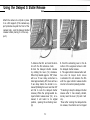
1
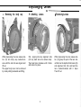
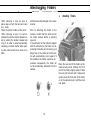
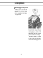
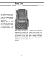
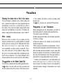
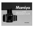
The Mamiya M645 1000S is a new improved
model of the M645, a camera widely acclaimed
for bridging the gap between small and large
format cameras by introducing the medium format, the purpose of which is to offer the world
of larger-negative quality to camera users who
are accustomed to the handling ease and compactness of 35mm SLR’s.
Every care has been taken to assure that your
Mamiya M645 1000s will provide you with years
of trouble-free service. However, to avoid possible mishandling, be sure to carefully read this instruction manual before using your new camera.
Special Features of the Mamiya M645 1000s
................ 3
Specifications
........................................................................
5
Names and Functions of Parts..........................................
7
Testing to See if the Camera Functions Properly ........ 1 6
Interchanging Lenses ........................................................
17
Interchanging Finders ........................................................
Focusing Screens ..............................................................
Inserting a Battery ..............................................................
Battery Check .......................................................................
Film Loading .......................................................................
Film advancing .....................................................................
Shutter Speed Dial ..............................................................
Aperture Ring/Stop-down Operation ..............................
Focusing ................................................................................
Shutter Release and Film Transport Mechanism ........
Unloading Film ....................................................................
T h e Neck Strap ....................................................................
Holding the Camera ...........................................................
Using the PD Prism Finder S.............................................
Using the CdS Prism Finder
.............................................
18
20
21
22
23
27
27
28
29
30
31
32
32
Using the Waist-Level Finder S .......................................
.. .. ..............
The Mamiya Moving Coil Electronic Shutter
Depth-of-Field .....................................................................
Using Flash ...........................................................................
Multiple-Exposures ............................................................
Infrared Photography .........................................................
Mirror Lock-up .....................................................................
Using the Delayed Shutter Release .................................
Interchanging the Film Advance Crank .......
....................
Tripod Socket ........................................................................
Time Exposures ..................................................................
44
47
48
49
50
..................................................................
Trouble-Shooting
Precautions ...........................................................................
Care of the Camera ............................................................
56
Mamiya-Sekor C Lenses ...................................................
Depth-of-Field Table .........................................................
Accessories ..........................................................................
35
39
2
50
51
52
53
55
55
57
58
59
62
63
Special Features of the
Mamiya ~.~ M645
\’ \
em-.__-~_---.-I~ 1000S
.-. The Mamiya M645 is a 6 x 4.5cm large-negative SLR that
is both extremely versatile and compact.
i
.
4.
Large-Negative Quality
The 6 x 4.5cm format offers approximately 3 times more
area than the 35mm format. Moreover, unlike the 6 x 6cm
square negative, there is little waste of the negative area.
For beautiful color enlargements everytime, the 6 x 4.5cm
format is the ideal format.
2.
Large, Bright Viewfinder
It becomes easy to catch the peak of action when looking
through the large, bright viewfinder. Because of the
Mamiya M645’s automatic diaphragm and quick-return
mirror, the viewfinder never grows dim. It is always bright,
ready for the next photograph.
5
.
a
Lightweight, dual-function Waist-Level Finder S
Interchangeable Finders
Despite the large-negative it produces, the Mamiya M645
A compact and lightweight finder which opens and closes
with a single touch, the Waist-Level Finder S is ideal for
is designed to handle as easily as a 35mm SLR. Its compact size and light weight are perfectly suited for the action photographer. It fits so well into one’s hands that it
copying, close-ups, low and high angle pictures, and
working in dim light. Additionally, it is instantly convertible
to an eye-level sports finder which accurately shows the
becomes an extension of his reflexes,
fields for the 80,110,150 and 210mm lenses, allowing one
to easily follow the quickest action.
3
n
Compact Design
Mamiya’s Moving Coil Electronic Shutter
0 Prism Finder
The Prism Finder is well-suited for action photography.
Whether the vertical or horizontal format is utilized, focus-
Mamiya has developed a revolutionary Moving Coil Electronically Controlled Shutter for the Mamiya M645. Electrical consumption of this new shutter is approximately
1/10 that of previous electronic shutters. Furthermore,
consumption remains constant regardless of the shutter
speed being used. In addition to accuracy, long battery
life is assured by this new shutter.
ing and following action is as easy as on a 35mm SLR.
0 PD Prism Finder
The PD Prism Finder employs silicon cells for full-aperture,
center-weighted readings. It is your assurance that every
negative will be properly exposed.
3
complete with meter coupling.
l Multiple-Exposure Provision
Merely lowering the multiple-exposure lever allows the
photographer to take as many multiple-exposures as he
wishes. During multiple-exposures, the exposure counter
does not move.
a CdS Prism Finder with built-in meter
Accurate through-the-lens exposure measurement is
possible with the CdS Prism Finder which couples to the
aperture of the lens and indicates the proper shutter
speed to set on the camera.
6 . Flatness
of the Film Plane
a Mirror Lock-Up
The Mamiya M645 is designed to have minimal mirror
shock; nevertheless, when it is necessary to completely
eliminate vibrations, all you have to do is lock the mirror
in the up position. To do so, simply lower the mirror lockup lever. Mirror lock-up provision makes close-up and
telephoto photography possible even at slow shutter
speeds.
l Two Shutter Release Buttons
The Mamiya M645 is equipped with two ideally located
shutter release buttons, so that regardless of how you
hold the camera, there is always a release button at your
finger tips.
Developed through Mamiya’s long experience as a manufacturer of 120/220 roll-film cameras, the Roll-Film Inserts
for the Mamiya M645 keep the film perfectly flat for edgeto-edge sharpness. Inserts are available for 120 or 220
roll-film.
7 . Multi-Coated
Lenses
Mamiya-Sekor lenses have achieved world-renown as professional lenses of exceptional contrast, high resolution,
clear definition, and excellent color balance. All the lenses
for the Mamiya M645, from wide-angle to telephoto, have
been multi-coated to maintain their high standard of performance even under adverse lighting,
A full range of accessories are available for the Mamiya
M645 to assist the photographer in capturing virtually any
a Built-in Delayed Shutter Release
a Depth-of-Field Preview Lever
A single touch on the Depth-of-Field Preview Lever,
which is ideally located on the camera body, stops the
type of image. Accessories include hand grips, interchangeable focusing screens, and auto extension rings
lens down to the preselected aperture for direct viewing
of the depth-of-field.
8 . Unlimited
Scope
4
-
Specifications
- --ll_-- ____
0 Camera Body
Camera Type:
6 x 4.5 cm electronic focal-plane shutter SLR.
Film Type:
120 roll-film for 15 exposures,
220 roll-film for 30 exposures
Actual Negative Size:
56 x 41.5mm (2-13/64” x1-41/64”)
Standard Lenses:
Mamiya-Sekor C (multi-coated)
80mm f/1.9, automatic diaphragm,
with meter coupler, 67mm filter size
Mamiya-Sekor C (multi-coated)
80mm f/2.8, automatic diaphragm,
with meter coupler, 58mm filter size
Lens Mount:
Mamiya M645 bayonet mount
Shutter:
B, 8-1/1000 sec.
Moving Coil Electronic Focal-Plane Shutter,
FP and X (1/60 sec.) synchronization,
Shutter release lock and shutter speed dial lock
provision
Battery Type:
One 6V silver-oxide battery 4SR44
(Eveready 544, UCAR 544, Mallory PX28)
or 6V alkaline battery 4LR44
Focusing Method:
Each Mamiya-Sekor lens is equipped with its own
helicoid focusing mount
Focusing Screen:
The standard focusing screen, which is interchangeable, has three focusing aids, a central split-image
rangefinder spot (wedge set at a 45° angle) surrounded by a micro-prism collar and outer ground
glass ring. A Fresnel lens assures corner-to-corner
brightness, and 94% of the picture-taking area is
visible.
Mirror:
Instant return, with mirror lock-up provision
Film Transport:
A single revolution of the interchangeable film advance crank transports the film. The camera is
equipped with double exposure prevention, but multiple exposure can be easily made.
Exposure Counter:
Progressive type, automatic reset, automatic
changeover with insertion of 120/220 roll-film inserts
Battery Check:
Depressing B.C. button illuminates green L.E.D if
battery condition is satisfactory.
Multiple-Exposure:
Lowering multiple-exposure lever makes multipleexposures possible; exposure counter does not
move during multiple-exposures.
Delayed Shutter Release:
Variable time delay of 5-10 seconds.
Depth-of-Field Preview Lever:
Spring-loaded, self-returning.
D
Interchangeable Finders
Prism Finder:
The image in the Prism Finder is right-side up, laterally correct, and moves in the correct direction;
magnification of 0.74X with the standard lens at infinity, built-on hot-shoe; comes with eyecup.
PD Prism Finder:
Prism Finder with built-in silicon cell, through-thelens, full-aperture, center-werghted metering: 7
LED’s visible in the viewfinder for correct or compensated exposure, with 100 ASA and f/1.9 lens,
meter coupling range of EV -1.15 - +19 (f/1.9,
8 sec.- f/22, 1/1000 sec.); with f/2.8 lens, EV 0- 19
(f/2.8, 8 sec. - f/22, 1/1000 sec.); camera body battery serves as power source; other features same as
Prism Finder.
CdS Prism Finder:
Prism Finder with CdS through-the-lens, full-aperture, center-weighted metering; zero method with
indicator needle; couples to aperture and shutter
speed manually set, power source, one 1.5V silver
oxide battery SR44 or alkaline battery LR44, with
100 ASA and f/1.9 lens, meter coupling range of
EV 2.85 - 17 (f/1.9, 1/2 sec. - f/11, 1/1000 sec.):
with f/2 8 lens: EV 4 - 18 (f/2.8, 1/2 sec. - f/16,
1/1000 sec.); other features same as Prism Finder.
Waist-Level Finder S:
Opens and closes with a single touch; magnification
of 1.3X (w/standard lens at infinity); diopter correction lenses interchangeable with standard magnifier;
built- in sports finder shows field for standard lens
and accepts a mask for 110,150, and 210mm lenses,
all fields showing approximately 80% of the picturetaking area.
Dimensions and Weight:
(width, height, depth, w/80mm f/1.9 lens)
(w/Waist-Level Finder S)
(w/1.9 lens)
(w/2.8 lens)
3-29/32”
x 3-15/16”
x 6-9/16”
55.4 oz
49.6 oz
(99.3 x 100 x 166.5mm)
(1570 g)
(1405 g)
(w/Prism Finder)
3-29/32”
x 4-27/32” x 6-9/16”
62.3 oz
56.4 oz
(99.3 x 122.7 x 166.5mm)
(1765 g)
(1600 g)
(w/PD Prism Finder S)
3-29/32” x 4-29/32” x 6-9/16”
66.5 oz
60.7 oz
(99.3 x 124.7 x 166.5mm)
(1885 g)
(1720 g)
(w/CdS Prism Finder)
3-29/32” x 4-29/32” x 6-9/16”
67.2 oz
61.4 oz
(99.3 x 124.7 x 166.5mm)
(1905 g)
(1740 g)
Depth w/80mm
f/2.8 lens; 6-1/16” (154mm)
6
Names- and
Functions of Parts (1)
- -___-Battery check lamp
Focusing screen
Five different
available.
types
are
Focusing screen lug
Mounting guide pin for
finder
Fits into the finder opening.
Alignment
dot
Alignment reference point
for mounting lens.
Depth of Field Preview
Lever
A slight upward push on the
lever stops lens down to
preselected aperture,
spring-loaded for self-return.
Shutter release button
(front)
When pushing in on this
button, the upper shutter
release button is coupled to
move in unison.
Equipped with cable release socket.
Shutter release lock ring
Turn lock ring and align with red dot to simultaneously lock both shutter release buttons.
To unlock, align with white dot.
If the green battery check lamp glows when the
battery check button on the opposite side is depressed, battery condition is good.
Flash sync terminals
With safety cover, only the
cover of the sync terminal
being used is removed.
Neck strap lug
Shutter speed
alignment mark
Shutter speed dial
Push in on safety lock built
into the center of the shutter speed dial while rotating
dial to desired speed.
Do not set dial to the @
position unless using the
PD or AE Prism Finder.
---4B Lens release button
Push in and simultaneously
turn the lens counterclockwise to remove.
Delayed Shutter Release Lever
To cock the built-in delayed shutter release, turn the
lever clockwise. Upon removing your finger from the
lever it will return to its former position, leaving the
Never touch the
surface of the mirror. activating lever exposed. Push the activating lever in
the direction of the engraved arrow to start the delayed shutter release.
7
Film plane mark
Battery check button
Indicates the position of the
film plane.
When depressed, the
battery check lamp on the
opposite side illuminates.
Used to check the condition
of the battery.
Back cover latch
While pushing in on the
memo clip, simultaneously
move the back cover latch
in the direction of the arrow
to open camera back.
Shutter release button
(upper)
Back cover
Mirror lock-up lever
When closing, apply pressure firmly and evenly in the
area of the back cover latch.
Push backward to lock
mirror in the up position.
Memo clip
Film advance crank
Holds the film box top as a
reminder.
One complete turn cocks
shutter and advances film.
Exposure counter
window
Multiple-exposure lever
Automatic changeover upon
insertion of 120 or 220 film
insert. Goes up to 15 with
120 film and up to 30 with
220 film.
Move the multiple-exposure
lever to the “multi” position
for multiple-exposures or to
release the shutter when
there is no film in the
camera.
8
Names_ and Functions of Parts (2)
@ Battery chamber cover
latch
Pull the latch toward the lens
to open the battery chamber.
I-
27
Battery chamber cover
Insert a battery into the battery
chamber
@ Tripod socket
1/4 inch tripod socket. To convert to a 3/8 inch socket, first
remove the small screw in the
base of the socket. Next, remove the inner socket by turning counterclockwise with a
coin.
30
Focusing ring
Distance scale
Depth-of-field scale
Alignment dot
Align with matching alignment
dot on camera body for rapid
lens mounting.
Aperture ring
A.M. Lever
Automatic diaphragm operation
when ”A” appears in the window.
Diaphragm stopped down to
preselected aperture when “M”
appears in window.
i___________
@ Exposure meter coupler
Couples the aperture ring to
a n y p r i s m finder with built-in
meter
10
ames and Functions of Parts
_ __(3)
Roll-Film Insert
(120 and 220 roll-film inserts are available)
Start Mark
Leader paper guide marks
After aligning the start mark on
the film’s leader paper with this
mark, the roll-film insert is ready
for insertion into the camera.
Indicates the direction leader
paper is to follow.
Film spool stud
Place film spool on film spool
stud so that the black side of
the leader paper faces up.
Release latch
Take-up spool stud
After squeezing in on both sides
of release latch, the roll-film
insert can be pulled out of
camera.
Attach empty spool to take-up
spool stud and insert the tip of
the leader paper into the spool
slot.
Film type index
(120 or 220)
Spool clip
Pull out and lower spool clip to
insert or remove film spools.
Insert roll-film insert into camera
with the film type index upright.
If the film type index is upside
down, roll-film insert will not fit
into the camera.
11
Prism Finder
Hot-shoe
(with safety cover)
Automatically fires cordless
flash units when the shutter
release button is depressed.
EYecUP
Eyepiece
Attach by sliding into the
grooves of the eyepiece.
Accessories such as eyecup, magnifier, and angle
finder can be attached.
Diopter correction lens
retainer ring
Finder release
Remove by unscrewing in
a counterclockwise direction. After inserting correction lens, replace retainer ring.
button
Turn clockwise until it stops,
push in, and the finder can
;E,;fted off the camera
11 22
-
Names-and
-. -Functions
“--of -Parts
- - -”(4)
PD Prism Finder S
(Detailed Instructions on pp. 35-38)
Aperture ring couplin
Couples to the exposure
coupler on the aperture ri
.*
.i,
- Meter switch
Pushing in on this switch when
the finder is attached to the
camera will turn on the meter
and a LED in the finder will light
up. Even if you release pressure
from the meter switch, the
meter will remain on for approximately 15 seconds and then
automatically turn off to conserve electricity.
Accepts accessories such as
eyecup, magnifier, and angle
finder.
Shutter speed dial
ASA window
ASA dial
Diopter correction lens
retainer ring
Remove by unscrewing in a
counterclockwise direction.
After inserting correction lens,
replace retainer ring.
Pull out and then turn.
Finder release button
Turn clockwise until it stops,
push in, and the finder can be
lifted off the camera body.
CdS Prism Finder
(Detailed instructions on pp.39-43)
Aperture ring
coupling pin
Shutter
Couples to the exposure
meter coupler on the
aperture ring.
Speed
Dial
Be sure to manually set the
shutter speed dial of the
camera body to the speed
indicated by this dial.
Hot-shoe (with safety cover)
Automatically fires cordless
flash units when the shutter release button is depressed.
Power switch
Set to OFF when the
meter is not being
used.
Accepts accessories such as
eyecup,
magnifier, and angle
finder.
ASA dial
Pull out and then turn
Attach by sliding into the grooves of the eyepiece.
ASA window
Diopter correction lens
retainer ring
Remove by unscrewing in a
counterclockwise d i r e c t i o n .
After inserting correction lens,
replace retainer ring,
Finder release button
cover
Remove the cover *with a coin and
Insert a 15V battery into the chamber
14
Turn clockwise until it stops,
push in, and the finder can be
lifted off the camera body.
Names and Functions
of Parts
(5)
.--~_ __.
Waist-Level Finder S
(For detailed instructions, see pp. 44-46)
Sports finder eyepiece
Retracted when not used.
Sports finder wire-frame
for standard lens
Retracted when not used.
Magnifier release
Auxiliary mask for 110,
Push in to raise the
magnifier.
Not necessary with standard lens.
Alignment dot for
changing magnifier
To remove magnifier, twist 90”
counterclockwise and lift out,
The magnifier is interchangeable with 5 types of magnifiers
with diopter corrections.
Finder release button
Turn clockwise until it stops,
push in, and the finder can be
lifted off the camera body.
-
Testing to See if the Camera Functions Properly
To release the shutter when there is no film in the camera, proceed as follows.
[For detailed instructions on particular points, refer to the page number shown
in parentheses.)
1. Insert a battery into the camera (p.21).
2. Set the multiple-exposure lever to “MULTI” (p.50).
(If you have just purchased the camera and the vinyl tube is still on the take-up
spool, there is no need to move the multiple-exposure lever.)
3. Set the shutter speed dial to any shutter speed other than the 0 red mark
(p.27).
4. Turn the film advance crank until it stops.
5. Align the shutter release lock ring with the white dot and release the shutter
(p.30).
When ready to load the camera with film, return the multiple-exposure lever to
its normal position. If this is not done, the film will not advance.
If the shutter is released without a battery in the camera, the mirror will lock in
the up position. To return the mirror to its normal position, depress the battery
check button (21) as far as it will go.
If the shutter is released with the shutter speed dial set to the red 0 position,
the mirror will lock in the up position. To lower the mirror, turn the shutter speed
dial in either direction (B or 1/1000 sec.).
At times it may be necessary to rotate the film advance crank two full turns to
cock the shutter when an empty take-up spool (without its original vinyl tube) is
in the camera.
,
,
16
Interchanging
Lenses
- ---_)II
l
Removing the body cap
While depressing the lens release button (13) turn body cap counterclockwise until the red dots are aligned and
lift out.
The upper body cover can be removed
by merely sliding backwards and lifting,
l Attaching
Lenses
While aligning the two alignment dots
(33 & 4), insert lens into camera body
Then twist lens clockwise until it clicks
and locks into place.
17
0 Removing Lenses
While depressing the lens release button (13) grasp the part of the lens barrel that has the depth-of-field scale (32)
and alignment dot (33) and twist the
lens counterclockwise until it stops
Then lift out.
I
-
Interchanging
Finders
- -___ -- --__l
*After removing a lens, be sure to
place caps on both the lens and camera body.
*Never touch the surface of the mirror.
*After removing a lens, it is recommended to lock the shutter release button by setting the shutter release lock
ring (7) in order to avoid accidentally
releasing a cocked shutter when placing the camera bodv face down on a
table.
All finders are interchanged in the same
manner.
Prior to attaching the finder to the
camera, confirm that the white dot on
the finder release button is pointing
upward.
If the white dot on the button is aligned
with the white dot on the finder, by depressing the button and removing your
finger from it, the white dot on the button will automatically point upward. In
this condition, the button cannot be depressed; consequently, the finder wiII
not be accidentally detached from the
camera.
18
Attaching Finders
b-
Y
Place the rear part of the finder on the
camera body while holding the front
part of the finder slightly upward. Slide
the rear part forward until it stops and
gently lower the front part of the finder
on to the camera body. It will then lock
into place.
o Removing Finders
1. Turn the finder release button clockwise until it stops (about 60”). Then you
will be able to push in on the release
button.
2. While pushing in on the release button with your thumb, lift the finder off
the camera body.
Precaution:
Do not leave both white dots aligned by turning the button while the finder is
attached to the camera. The finder may become detached when the button IS
occasionally depressed, possibly causing damage
If you depress the button to point the white dot upward while the finder is attached to the camera, be sure to depress the finder against the camera body,
otherwise the finder will not be locked into place.
19
Focusing Screens
0 Interchanging Focusing Screens
The focusing screens are readily interchangeable. Five different focusing
screens are available to meet various
photographic needs.
Remove the finder, grasp the focusing
screen lug (2), pull up, and lift out. To
replace screen, gently insert and lightly
push it in on both sides until it stops.
*Since the rear surface of the screen
is made of plastic, be careful not to
scratch it when interchanging screens.
20
Inserting
-~ a Battery
The Mamiya M645 uses one 6V silver
oxide battery 4SR44 (Eveready No
544, UCAR 544, Mallory PX28 or
equivalent or alkaline battery 4LR44
1. Pull the battery chamber cover latch
(26) slightly toward the lens and the
chamber cover will open
2. Next, insert the battery, exercising
caution that the + poles match those
shown on the diagram of the chamber.
Battery removal will be simplified if the
battery removal ribbon (A) passes under
and over the battery.
21
CAUTION:
1. Carefully wipe the contacts of the
battery before inserting it into the chamber. Failure to do so could result in poor
electrical contact and consequent erratic functioning of the camera
2. When the camera is not used for a
long period of time, remove the battery
and store it in a cool, dry place
3. When replacing a battery, properly
dispose of the used battery immediately as it is potentially dangerous The
batteries are explosive and should
therefore never be thrown into a fire.
4. A battery that is not used for a long
period, even if it is properly stored in a
dry, cool place, may lose some of its
charge. Consequently, check its condition after replacing it in the camera with
the battery check button.
Battery
Check
-..---
This camera is designed for use with
either silver oxide or alkaline batteries.
Although both types offer adequate
performance, silver oxide batteries
last much longer
IMPORTANT. When using the PD
Prism Finder, make it a point to use
silver oxide batteries when available
(in this instance, battery life is shortened if alkaline batteries are used)
When the battery check button (21,
located above the film advance knob)
is depressed, the battery check lamp
(8, located above the shutter speed
dial) illuminates. If the battery check
lamp fails to go on, it is time to replace
the battery.
22
* When the battery is completely exhausted, the opened shutter will not
close. At this time, if the battery check
button is pushed all the way down as
far as it will go, the shutter will then
close.
Film
Loading
____-----.-0 Loading the Film
1. While gently pushing in on the memo
clip (19), move the back cover latch (17)
in the direction of the arrow and the
camera back cover will open.
2. While squeezing in on both sides of
the release latch (37) pull the roll-film
insert out of the camera body. Place
the film insert on a table making sure
that the film type index (42) is not upside
down. Then pull out and lower the
spool clips found on the left-hand side
23
3. Align the right-hand side of an empty
spool with the lower spool stud (41).
Then return the spool clip (38) to its
former position, making sure that the
left-hand side of the spool is properly
held by the spool clip.
4. In the same manner insert a roll of
film in the upper compartment.
5. Make sure that the black side of the
leader paper faces up.
6. Gently pull out some of the leader
paper, pulling it over and around the
pressure plate. Then insert the tip of
the leader paper into the slot of the
take-up spool.
7. Gently rotate the take-up spool in
the direction of the arrow until the start
mark of the film is aligned with the start
mark on the spool clip (36).
k The above step is to be completed
before the roll-film insert is placed into
the camera.
24
0 Using Roll-Film Designed for Six Exposures
* Never load film in direct sunlight. Load it in the shade
or in your own shadow.
* Roll-film inserts for both 120 and 220 film are loaded in
the same manner. The exposure counter advances to 15
when the 120 film insert is used, and to 30 when the 220
film insert is used.
Make absolutely sure to match the film insert with the film
type being used. If the wrong insert is used, the correct
film plane will not be maintained and optimum sharpness
will not be achieved. Moreover, if 120 film is used in the
220 film insert, there is the danger of the leader paper
getting caught in the shutter causing damage to the camera.
* Before placing the film insert into the camera, make sure
the leader paper on the take-up spool is flat and lies evenly
between the two edges of the take-up spool. The take-up
spool should be wound sufficiently tight to make it impossible for the leader paper to ride over the edge of the
take-up spool.
* Always align the start marks of the film and spool clip
before placing the film insert into the camera. (If the start
marks are aligned within the camera with the aid of the
film advance crank, the first frame will not be correctly
positioned.)
If you wish to use roll-film designed for six 6 x6cm exposures, follow the procedure outlined below.
1. Load the film in a 120 film insert and use in the normal
way. The film will take 7 exposures.
2. After 7 exposures have been taken, set the shutter
speed dial to 1/500 sec., wind the film advance knob and
release the shutter 4 more times (the exposure counter
will indicate “11”).
3. Wind the film advance knob once again so that the exposure counter indicates "12”, open the back cover, and
remove the film insert. (Do not release the shutter when
the exposure counter indicates "12".)
4. Completely wind the remaining leader paper around
the film take-up spool.
* If the film in the camera is completely wound onto the
take-up spool, there is the danger of the tip of the leader
paper getting caught in the shutter curtain and damaging
the camera.
25
0 Memo Clip
0 Insertion of the Film Insert
1. Grasp both sides of the release
latch (37) of the film insert, making sure
that the film type index (42) is not upside
down, and place the film insert straight
into the camera body. After the film
insert has completely entered the
camera body, let go of the release
latch.
2. Press in on the outer edges of the
release latch (indicated by the arrows
in the photograph above) and the rollfilm insert will lock into place. (If the
roll-film insert does not go all the way
in on the right-hand side, turn the film
advance crank slightly while pushing
in on the right side of the film insert.)
3. After insertion has been completed,
securely close the camera back cover.
* If the film advance crank moves
slightly from the time the film insert is
placed into the camera to the time the
back cover is closed, there will be no
ill effects. However, if the film advance
crank moves too much, the first frame
will be fogged.
26
The memo clip found on the camera
back cover can be used to hold the
film box top.
* The memo clip also doubles as a
safety lock to prevent the camera back
from accidentally opening. If excessively thick paper is placed in the memo
clip, it will no longer simultaneously
serve as a safety lock.
1. After the film has been placed into
the camera make sure that the multipleexposure lever (25) is aligned with the
white dot and not with the word
“MULTI”.
2. Wind the film advance crank until it
stops and the number 1 will appear in
the exposure counter window (20). The
shutter is now cocked and the camera
is ready for the first exposure.
1. Align the shutter speed of your
choice with the white alignment index
by rotating the shutter speed dial (12)
in either direction while pushing in the
safety lock button located in the center
of the dial
2. Color Coding
( a ) G r e e n figures r e p r e s e n t full
seconds, all other figures represent the
denominator of a fraction. (Thus, 30)
equals 1/30 sec.)
(b)Orange represents caution. The
shutter speeds appearing in orange
are not suitable for hand-held shooting.
Use a tripod.
27
Aperture Ring/Stop-down
Operation
(c)The red B represents BULB. The
shutter will remain open as long as the
shutter release button is depressed
when the shutter speed dial is set to B.
(d)The red 60X represents the highest
permissible shutter speed for electronic
flash synchronization.
(e) The redOmark is the position the
shutter speed dial is set to when the
PD Prism Finder is used.
* If the shutter is released with the
shutter speed dial set to the@ position
and the PD Prism Finder is not attached
to the camera, the shutter will lock in
the open position. If the camera is left
in this condition, the battery will lose
its power within several hours, so rectify the situation at once. (Moving the
shutter speed dial to B or 1/1000 sec.
will close the shutter.)
*While gently pushing in on the safety lock button, the shutter speed dial
can be set to any click-stop and then
locked into place by releasing the lock
button; however, the shutter speed dial
can not be used at intermediate speed
positions.
0 Depth-of-Field Preview Lever
Keep the AM lever of the lens (29) at
the Auto position (the letter A is visible),
and whenever desiring to view the
depth-of-field, merely push all the way
upward on the depth-of-field preview
lever (5) to stop the lens down to the
preselected aperture. Releasing the
preview lever will return the lens to its
maximum aperture.
0 AM Lever
Set the desired f/stop on the aperture
ring (34) by aligning the f/number with
the red reference dot (A). (The aperture ring has a click stop for each
f/stop. In-between clicks can also be
used)
28
Moving the AM (Auto/Manual) lever(29)
of the lens so that M is visible will stop
the lens down to the preselected aperture.
*When desiring to use the depth-offield preview lever with the 70mm f/2.8
!ens (w/built-in between-the-lens shutter), first set the shutter speed ring of
the lens to F (Focal plane shutter) index
mark.
Focusing
1. While looking through the viewfinder,
adjust the focusing ring (30) until the
most important part of the subject appears sharp.
2. Extremely accurate focusing is simplified by the split-image rangefinder
spot located in the center of the focusing screen. Its wedge is set at a 45°
angle, making it possible to use either
horizontal or vertical lines of the subject for precise focusing. The splitimage rangefinder spot is surrounded
by a microprism collar which fractures
the image whenever it goes slightly
out-of-focus; consequently, it is an invaluable aid for pinpoint focusing accuracy.
3. The outer ground glass ring (which
encircles the microprism collar) can
also be used for focusing.
Since the Mamiya M645 is an SLR, the
photographer always sees in the viewfinder exactly what will appear on the
film, regardless of the lens or accessory being used.
29
Moreover, simply moving the depth-offield preview lever upward will allow
one to preview the depth-of-field and
appearance of out-of-focus images.
* As an accessory, Mamiya offers
diopter correction lenses which can be
attached to the prism finders, and
diopter lenses for the waist-level
finder. Near and farsighted persons
will find these accessories useful for
obtaining accurate focus.
:
Shutter Release
and Film Transport
\ \ \ \ \ \ ’ \
-.-.-.-.-.
-__ Mechanism
--..-p
0 Shutter Release Lock Ring
The shutter release button is equipped
with a lock ring to prevent accidental
release of the shutter.
1. When you wish to release the shutter,
turn the shutter release lock ring so
that the white dot (B) is aligned with the
dot (A) on the camera body.
2. Aligning the red dot (C) of the shutter
release lock ring with the dot on the
camera body will simultaneously lock
both shutter release buttons.
* After the fixed number of exposures
has been taken (15 or 30), the shutter
release button automatically locks.
*If the film is advanced while depressing the shutter release button, the shutter will be released at the instant the
film is fully advanced. Do not attempt
to take pictures in this manner as a degree of camera shake is inevitable.
* If the PD Prism Finder is not attached
to the camera body and the shutter is
released with the shutter speed dial
set to the @ position, the mirror will lock
in the raised position and the shutter
1. When releasing the shutter, you may
use either the front or upper shutter will remain open. (Moving the shutter
speed dial to B or 1/1000 sec. will lower
release button.
the
mirror and close the shutter.)
2. After releasing the shutter, the film
* Use of the multiple-exposure lever
advance crank is automatically unis explained on page 50.
locked, making it possible to transport
* The front shutter release button is
the film to the next frame.
threaded to accept cable releases.
Please notice the following points regarding the film transport mechanism: *Do not strongly depress the upper
shutter release button while simulta* A built-in safety lock prevents the
neously advancing the film. If this is
shutter from being released if the film done, the film advance automatic stop
advance crank is not fully wound or if mechanism will be disengaged, and
the exposure counter is between S the film will advance even during the
and 1
operation of the shutter. Moreover, the
30
Unloading
Film
-___-~--mirror may lock in the up position,
which results in rapid depletion of the
battery. Should the mirror lock in the
raised position for the above reason,
first continue to rotate the film advance
crank until it stops (after the fixed number of exposures (15 or 30) have been
taken, the film advance crank should
be rotated more than one full turn),
then lower and raise the mirror lock-up
lever, and the mirror will return to its
normal position, simultaneously terminating needless electrical consumption
(The only time it is necessary to strongly
depress the upper shutter release button is in the event that the mirror locks
in the raised position upon releasing
the shutter when working at extremely
low temperatures. At such a time, if the
film is advanced afler first strongly depressing the release button, then lower
and raise the mirror lock-up lever, the
mirror will lower and the camera will be
ready for the next exposure.)
,,,
1. After the fixed number of exposures
have been taken (15 for 120, 30 for 220)
the shutter release button will lock. At
that time, wind the film advance crank
until the leader paper is completely
wound onto the take-up spool. (When
winding is complete, resistance will
no longer be felt on the film advance
crank.)
2. Open the back cover, remove the
roll-film insert and the exposure counter
will reset to S (Start). The exposure
counter will not reset to S if the insert
is not removed.
3. Remove the film from the film insert,
exercising care that the film does not
loosen, and seal it.
31
>,
,
- -The
- - -Neck
- - - Strap
. -.
Methods
of holding
the camera
securely
- - - ~-- --______
_____-
0 Attaching to Camera
0 Eve Level Owration
No matter how carefully one focuses
the camera, if there is camera movement during the instant the shutter is
released, sharp pictures are unlikely.
To eliminate camera movement, care
must be taken regarding the method
of holding the camera and releasing
the shutter.
Place the neck strap fastener over the
neck strap lug on the camera body and
gently pull it away from the camera
while pressing it toward the body until
it clicks and locks in place.
0 Removing from Camera
While pushing in on the rear blade of
the neck strap fastener with your thumb,
slide it forward and remove.
32
0 Waist-Level Operation
0 Hand Grips
When hand-holding the camera with
the waist-level finder attached, adjust
the length of the neck strap to take up
all slack and support the camera against
the body. As accessories, Mamiya
offers a selection of hand grips which
not only help to eliminate camerashake, but are also convenient for
carrying the camera.
34
Using theII
PD--~-__IPrism Finder
-__l.--_I~S (1)
I) Special ‘Features
\
1. The PD Prism Finder is an eye- level finder with a built-in silicon
photo diode exposure meter and electronic shutter control circuit.
2. The PD Prism Finder offers complete coupling of the lens aperture, shutter speed, and film speed (ASA)
3. Seven LED’s are built i n t o the viewfinder system. A green LED
indicates correct exposure and red LED’s indicate over, under, and
compensated exposure
4. The built-In meter covers a broad range, is highly accurate even
in dim light, and has a rapid response because it utilizes silicon
photo diodes.
l
Specifications
Viewfinder: 0.74 magnification with standard lens at
infinity, built-on hot-shoe, comas with
Metering System:
through-the-lens,
full-
Since the PD Prism Finder utilizes the
battery in the camera body, a timer is
incorporated into the meter switch of
the PD Prism Finder to prevent unnecessary electrical consumption.
1. Set the camera body shutter speed
dial to the PD Prism Finder positron@
located between B and 1/1,000 sec.
If the shutter speed dial is set to a position other than 0, the PD Finder and
camera body will not be electrically
connected. Consequently, the viewfinder LED’s will not illuminate.
ASA
DIN
6400
(5000)
(4000)
(39)
l
l
3200
(2500)
(2000)
(36)
l
l
1600
(1250)
l
800
2. Attach the PD Prism Finder to the
camera body.
3. Turn the aperture ring of the lens so
that the exposure meter coupler (35) of
the lens and the aperture ring coupling
pin (A) of the PD Finder engage.
+ Be sure to check for proper coupling.
If the aperture ring coupling pin (A) is
not properly seated in the fork of the
exposure meter coupler (35), use a pen
(or similar device) to push the aperture
ring coupling pin into its proper position
into the fork.
4. Pull out and turn the ASA dial (B)
until the appropriate ASA number
appears in the window.
(650)
(500)
l
400
*
(250)
l
l
100
l
50
36
(20)
(19)
(18)
e
l
25
(23)
(22)
(21)
l
(40)
(32)
(26)
(25)
(24)
l
(80)
(64)
(29)
(28)
(27)
(320)
200
*Always set the AM Lever on the lens
to “A”, otherwise correct metered exposure cannot be obtained. For the
same reason, do not touch the Depthof-field Preview Lever when making
an exposure measurement.
(32)
(31)
(30)
l
(160)
(125)
(35)
(34)
(33)
l
(1000)
(38)
(37)
(17)
(16)
(15)
- _-- ~--
$ (2) -. .- - the PD Prism Finder
_____-----Using
5. Push in and release the meter switch
(C) to turn on the meter. With the meter
on and while looking through the viewfinder, adjust the aperture ring (34) or
shutter speed dial (D) until the central
(green) LED in the right-hand side LED
panel illuminates, indicating correct
exsosure.
The meter circuit remains on as long as
the meter switch is depressed. After
releasing your finger from the switch,
it will stay on approximately 15 seconds
longer, then the meter will automatically turn off to conserve electrical
consumption.
*If two LED’s illuminate simultaneously, make fine adjustments with the aperture ring until the central green LED
appears the brightest.
*Remember to adjust the shutter
speed with the PD finder shutter speed
dial and to keep the camera body
shutter speed dial set to 0.
37
*The shutter speed dial has clickstops at full one speed intervals and
cannot be used at intermediate positions. Although the aperture ring has
click-stops at one stop intervals, intermediate positions may also be used.
*The shutter speed dial of the PD
Prism Finder
- - . has
.-_ a stronq click-stop at
1/1000 sec. to enable the_ user
. .to_ tell
.
by touch alone, without any need to
remove his eye from the viewfinder,
when he is changing from the adjacent
1/500 sec. or 8 sec. shutter speed to
1/1000 sec.
0 Exposure Compensation
The LED Panel incorporated into the PD
Prism Finder simplifies exposure compensation, assuring perfect exposures
everytime. Each LED represents a
full stop increment and plus and minus
signs are indicated within the viewfinder to assist in compensating.
The uppermost LED represents three
or more stops overexposure, and the
lowermost LED represents three or
more stops underexposure.
e Compensation Hints
1. For strongly back-lit subjects outdoors, set the exposure to + 1 (the red
LED directly above the green one).
2. To photograph a person indoors,
seated next to a window and strongly
back-lit, set exposure to + 2.
3. When photographing interiors, to
compensate for the bright interior lights,
set exposure to +1 or + 2.
4. When copying white documents, set
exposure to +2. If a standard gray
card is used to determine exposure,
no correction is necessary.
5. When photographing a brightly lit
subject against a dark background,
such as a night club performer, set
exposure to - 1 or - 2.
6. Brightly lit night scenes, such as city
streets, are usually rendered most
naturally with the correct exposure
(green LED).
7. When photographing extremely dark
subjects (e.g. close-up of a black cat),
set exposure to - 1.
* The exposure compensation or LED
panel can also be used to increase the
ASA range to 3 - 51200. For example,
with the ASA dial set to 25, instead of
using the green LED for correct exposure, use the +3 LED when using
ASA 3 film.
* Since the upper and lowermost
LED’s represent 3 or more stops difference from the central (green) LED,
whenever compensating by 3 stops,
first adjust the aperture or shutter
speed for 2 stops of compensation and
then move the aperture ring or shutter
speed dial one more click stop for 3
stops of compensation.
38
Correct Exposure Measurement
*The TTL metering system of your
PD Prism Finder makes it unnecessary
to consider such factors as the difference in angle of view of interchangeable lenses, filter factors, or exposure
increase for macrophotography. (For
accurate exposure measurement when
taking close-ups, be sure to carefully
read the instructions packed with the
auto bellows, reverse ring, etc.)
*In macrophotography, the amount of
light reaching the film varies in accordance with the extension of the
auto bellows, extension rings, etc.
Consequently, for accurate results be
sure to first focus on the subject before
taking an exposure measurement,
*To prevent extraneous light from entering the eyepiece and influencing the
exposure reading, keep your eye close
to the eyecup when making an exposure measurement.
a Inserting the Battery
------\
i
0 Special Features
I
1. The CdS Prism Finder is an eye-level finder with a built-in CdS
exposure meter for accurate exposure measurement.
2. It couples to the aperture when attached to the camera.
3. An exposure meter indicator needle is visible in the viewfinder to
Meter Coupling Range: (with f/1.9 lens and 100 ASA f i l m )
I
I
MS-76 or equivalent or alkaline battery LR44 as the power source,
0 Method of Use
1. Remove the battery chamber cover
by rotating it counterclockwrse with
the aid of a coin.
2. The underside of the battery chamber cover bears a + mark. Be sure to
have the + marks of battery and chamber cover face each other as the battery is inserted. Then securely retighten
battery chamber cover
*Wipe battery with a soft cloth before
inserting into battery chamber, as a
soiled battery may fail to make, or
maintain, proper contact
*When the finder is not used for a
long period of time remove the battery
and store it in a cool, dry place.
*Never throw used batteries into a
fire, or attempt to charge a battery.
*Be sure to check for proper coupling.
If the aperture ring coupling pin (A) is
not properly seated in the fork of the
exposure meter coupler (35) use a pen
(or similar device) to push the aperture
ring coupling pin into its proper position
into the fork.
*Always set the AM Lever on the lens
to “A”, otherwise correct exposure cannot be obtained. For the same reason,
do not touch the Depth-of-Field Preview Lever when making an exposure
measurement.
1. Attach the CdS Prism Finder to the
camera body.
2. Turn the aperture ring of the lens so
that the exposure meter coupler (35)
and aperture ring coupling pin (A) of
the CdS Prism Finder engage.
40
.
Using the CdS Prism Finder
..- (2)
3. Set the meter of the CdS Prism Finder to the correct ASA. To do so, pull
out and rotate the ASA dial (B) so that
the appropriate ASA number appears
in the window, aligned with the index
mark.
4. Turn the exposure meter switch to
ON.
/
41
5. Set the shutter speed dial on the
camera body to the desired speed, and
then set the shutter speed dial of the
CdS Prism Finder to the same speed.
(Examples of recommended shutter
speeds to use with 100 ASA film would
be 1/250, or 1/l25 sec. outdoors on a
sunny day, 1/125 or 1/60 sec. outdoors
on a cloudy day, and 1/30 sec. when
working indoors,)
6. To set the correct exposure, rotate
the aperture ring until the exposure
meter indicator needle visible in the
viewfinder is centered between the
two brackets visible on the right-hand
side of the focusing screen.
0 Aperture Priority Method
If the indicator needle cannot be centered even after rotating the aperture
ring as far as it will go, the exposure
must be adjusted by rotating the CdS
Prism Finder shutter speed dial. If the
indicator needle is too high, set the
shutter speed dial to a shorter (“faster”)
speed; it too low, set to a longer
(“slower”) speed. After adjusting the
shutter speed dial of the CdS Prism
Finder, if the indicator needle is slightly
off-center, make final adjustments with
the aperture ring.
Whenever changing the setting of the
shutter speed dial of the CdS Prism
Finder to adjust for exposure, do not
forget to set the shutter speed dial of
the camera body to the same setting.
7. After the above steps have been
completed (centering of the indicator
needle), exposure setting should be
correct, and the picture may be taken.
1. When desiring to set the aperture
first set the aperture ring to the desired f/stop, and then adjust for exposure by rotating the shutter speed
dial of the finder until the indicator
needle is centered between the
brackets
2. Check the setting of the finder shutter speed dial, and set the same setting on the shutter speed dial of the
camera.
*When adjusting for exposure with the
CdS Prism Finder shutter speed dial,
do not use any intermediate positions,
but always set the dial to a click-stop
If the indicator needle cannot be perfectly centered with the shutter speed
dial at a click-stop position, make final
adlustments with the aperture ring.
42
The brackets visible in the viewfinder
not only indicate correct exposure, but
are also notched to indicate *2 f/stops
(see diagram) to simplify exposure
compensation for unusual lighting.
When the exposure meter switch is set
to OFF, the indicator needle rests at
the bottom position.
Correct Exposure 0
Using- the- CQS
-.
- ~.Prism
. . _ .-.-~ Finder
_.. .- (3)
l
Meter Coupling Range
The range of usable shutter speeds
varies in accordance with the film
speed (ASA). As the shutter speeds
shown in the shaded area of the diagram below are beyond the range of
the meter, the shutter speed dial is
provided with a safety lock to prevent
one from entering the non-usable zone.
For example, it can be seen from the
diagram that 1/8 sec. is in the nonusable zone when using film rated at
800 ASA (or higher); consequently,
when the ASA dial of the CdS Finder is
set to 800, the shutter speed dial cannot be set to 1/8 sec.
*To conserve battery power, keep the
exposure meter switch set to OFF
whenever the meter is not in use. Even
when forgetting to set the switch to
OFF, whenever the CdS Prism Finder
is removed from the camera, the exposure meter is automatically switched
off because of the small safety switch
built into the bottom of the finder.
*To obtain optimum results, follow the
same precautions outlined for the PD
Prism Finder (see “Correct Exposure
Measurement”, p.38).
Usable Shutter Speeds (unshaded area)
\
Using the Waist-level Finder S (1)
0 Opening the Finder Hood
0 Closing the Finder Hood
0 Raising the Magnifier
Pull up on the finder hood opening
flange to open the finder.
First, push in on the sides; next, push
the front cover and back together to
fold the finder.
Push in on the magnifier release button
to raise the magnifier.
44
Using
the- Waist-level
Finder S (2)
~ -_-_- __ -_ _-~-0 Lowering the Magnifier
To lower, push down on the edge of
the magnifier board until it locks into
place.
0 Interchanging Magnifiers
Removing the Magnifier
While holding the finder side panels
with the left hand so that the magnifier
board (A) is not lowered, grasp the
edge of the magnifier with the fingers
of the right hand and twist counterclockwise to remove.
Attaching a Magnifier
Align the white dots of the magnifier
and magnifier board; drop magnifier
into magnifier board, and twist clockwise until magnifier clicks and locks
into place.
45
* In addition to the standard magnifier
(-1.5 diopters), magnifiers of + 2, +l,
0, - 2, and - 3 diopters are available
for near and farsighted users.
The standard -1.5 diopter magnifier is
designed for users, whether eyeglass
wearers or not, that have no trouble
seeing a subject 2.5 ft. (70cm) away
clearly. For those who have difficulty
seeing clearly at such a distance, or for
those who wish to remove their eyeglasses in order to see the entlre focusIng screen field, please use a diopter
lens which is available as an optional
accessory However, before making a
purchase, try the diopter lens at your
Mamiya dealer to make sure it matches
your eye.
0 Using the Sports Finder
0 Using the Auxiliary Mask
With Waist-Level Finder S in the closed
position, first raise the sports finder
eyepiece (B) to a vertical position. The
eyepiece sight folds into the eyepiece
base; when lifted out of the base, the
eyepiece sight will stay in a vertical
position because of the eyepiece
spring. Next, lift the wire-frame (C) of
the sports finder.
As the Waist-Level Finder Hood can be
opened even with the sports finder
mask raised, focusing can be quickly
and easily checked. (However, if the
finder hood is first opened, the sports
finder wire-frame cannot be raised.)
The wire-frame of the sports finder indicates the field for the 80mm lenses.
When desiring to use the 110, 150, or
210mm lens, the auxiliary mask must be
attached to the wire-frame. When desiring to open the Waist-Level Finder
Hood, while the auxiliary mask is attached to the raised frame, first pull the
bottom of the auxiliary mask out to the
second notch, in order to prevent the
auxiliary mask from blocking the finder
hood.
46
Setting the auxiliary mask to the second
notch has no adverse effects on the
accuracy of the indicated fields; therefore, it is perfectly acceptable to use
the sports finder in this condition. Additionally, when the auxiliary mask is set
to the second notch, it is also possible
to lower it over the closed finder hood,
although it is recommended to remove
the auxiliary mask before lowering the
wire-frame in order to minimize
scratches on the surface of the plastic
mask.
Depth-of-field refers to the total area (foreground and background) which will
appear in focus (sharp). The area of sharpness (depth-of-field) depends upon
the distance the lens is focused at, the f/stop (or aperture) being used, and the
focal length of the lens. The area that will appear sharp can be determined in
three ways:
1. The Depth-of-Field can be directly viewed on the focusing screen by gently
pushing the Depth-of-Field preview lever upward, as far as it will go. When released, the spring-loaded lever will return to its original position and at the
same time, the diaphragm of the lens will return to maximum aperture for bright
viewing.
2. The depth-of-field can also be determined by referring to the depth-of-field
scale engraved on the lens and which lies directly above the aperture ring. The
f/stop numbers are engraved on both the right and left-hand sides of the center
reference mark. Simply locate the f/stop (aperture) you are using and read the
figures which appear above the f/stop number on the distance scale of the lens.
For example, with the 80mm f/2.8 lens focused at 10ft. (3m) and the aperture ring
set to f/16, the depth-of-field scale reveals that everything from about 7ft. (2m)
to about 20ft. (6m) will appear sharp (see photograph).
3. The lens can also be-stopped down to the preselected aperture for direct
viewing of the Depth-of-Field by using the AM lever on the lens instead of the
camera Depth-of-Field preview lever. To do so, move the lever so that M
(Manual) is visible. You can take a picture in this condition while observing the
Depth-of-Field.
*When desiring to use the Depth-of-Field preview lever with the 70mm f/2.8
lens (w/built-in between-the-lens shutter), first set the shutter speed ring of the
lens to F (Focal plane shutter) index mark.
48
Using__.--Flash
~----
_‘\
\
\’
\
1. Flash units can be attached to the
camera’s tripod socket or to the accessory shoe of the hand grip.
2. The Mamiya M645 has two sync
terminals which are used in the following way:
(1) When using an electronic flash, plug
the synchronization cord into the X terminal and set the shutter speed dial to
1/60 sec. or longer (1/30 - 8 sec.).
(2) When using FP flashbulbs, plug the
cord into the FP socket and set the
shutter speed dial to 1/60 sec. or shorter
(1/125 - 1/1000 sec.).
Precaution when Using Flash
When using the X-sync terminal of the
camera body, be sure to insert the
plastic safety cover into the hot-shoe,
and when using the hot-shoe, be sure
to insert the appropriate safety cover
into the X-sync terminal. This procedure will prevent the possibility of receiving an electric shock while an electronic flash is attached and accidentally
touching the terminal not being used.
Flash Synchronization Chart
_\ ,\
(3) For MF and M bulbs, use the X terminal and set the shutter speed dial to
1/30 sec. or longer for MF bulbs, and
1/15 sec. or longer for M-type bulbs.
t The Prism and PD Prism Finder are
equipped with a hot-shoe and offer
cordless flash operation for flash units
that have a hot-shoe contact.
* If the flash duration of an electronic
flash is longer than 1/1000 sec. (e.g.
1/600 sec.) set the shutter speed dial to
1/30 sec. (not 1/60 sec.) or longer.
t When using flash, carefully read the
instructions packed with the flashbulbs
or flash unit to avoid making errors.
When using infrared film it is necessary to make a focusing adjustment in order to achieve accurate focus. This
focusing adjustment is particulary important when:
a) using non-wide-angle lenses
b) taking close-ups
c) shooting at wide apertures
When the white dot of the multiple-exposure lever (25) is
aligned with MULTI, the double-exposure prevention
mechanism is disengaged, so that the shutter can be
cocked with the film advance crank without moving the
film, making multiple-exposures possible. (When making
multiple-exposures, the exposure counter does not advance.)
When desiring to make a multiple-exposure, set the multiple-exposure lever to MULTI. (It can be set to MULTI
either before or after the initial exposure of the multipleexposure.) After making the initial exposure, recock the
shutter with the film advance crank and then make the
second (double) exposure, repeating as often as desired.
Focusing Adjustment Procedure
1. The red dot or line on the right side of the center reference line (also red) is the infrared mark.
2. After focusing in the usual manner, check the distance
on the distance scale that is aligned with the center reference mark of the lens, and then make the focusing adjustment by turning the focusing ring slightly in the direction
indicated by the arrow in the accompanying photograph
so that the distance just observed is aligned with the
infrared mark.
* For information regarding the proper filter and exposure,
refer to the data sheet packed with the film.
Remember to return the multiple-exposure lever to its
original position upon completion of the multiple-exposure.
* To release the shutter when there is no film in the
camera, set the multiple-exposure lever to “MULTI”.
50
Mirror
Lock-up
.- -.-When the camera is mounted on a tripod for copy work or telephotography at
long (slow) shutter speeds, the small amount of vibrations due to”mirror-bounce”,
which normally are of no consequence, may cause blurring of the image due to
the high magnification encountered in extreme close-ups and telephotography.
Mirror shock can be eliminated by locking the mirror in the up position before
making the exposure.
1. To lock the mirror up, merely move the mirror lock-up lever (23) backwards,
until it is horizontal (the lever may be lowered either before or after cocking the
shutter).
2. With the shutter cocked, release the shutter with a cable release. After
releasing the shutter, you may wind the film advance crank with the mirror still
in the up position if you wish.
* Return the mirror to its normal position immediately after completing all of
your mirror lock-up photography.
*When using the 70mm f/2.8 lens (w/between-the-lens shutter), be sure to
refer to the instructions packed with the lens.
51
Using the Delayed S Shutter Release
..~..
Attach the camera to a tripod or place
it on a firm support. (If the camera support protrudes beyond the front of the
camera body, cock the delayed shutter
release before placing it on the support).
1. Advance the film and cock the shutter with the film advance crank
2. Cock the delayed shutter release
by rotating the lever (14) clockwise
When fully rotated (approx. 180°) there
will be a 10 sec. delay, and when rotated approximately 90°, there will be a
5 sec delay before the shutter is released (Rotating the lever less than 90°
will fail to cock the delayed shutter
release.) When the spring-loaded delayed shutter release lever (14) is released, it will return to its original
position, xposing the activating lever
(A)
52
3. Push the activating lever in the direction of the engraved arrow to start
the delayed shutter release.
4. The upper shutter release button will
move when the delayed shutter release
is activated. Do not advance the film
until the upper shutter release button
returns to its normal (raised) position.
*If desiring to stop the delayed shutter
release after it has already started,
merely reset the lever (14) and it will
stop.
*Even after cocking the delayed shutter release, the shutter can be tripped
Interchanging the Film Advance Crank
with the Shutter release button, bypassing the delayed shutter release, as
often as desired
*If the delayed shutter release is inadvertently started when the shutter is
uncocked, it will stop after partially
functioning. Then, reset the lever, advance the film, and push the activating
lever to start the delayed shutter release. If the film is advanced, at such a
time, before resetting the delayed shutter release,the delayed shutter release
will automatically commence operating
the moment the film is fully advanced,
tripping the shutter a few moments
later.
For the same reasons outlined above,
the shutter release lock ring should
also be set to the unlocked position
before starting the delayed shutter release.
*When attaching the camera to a
large, professional tripod, the camera
support may protrude beyond the front
of the camera body However, if the
camera is attached to such a tripod
with the accessory Mamiya Quick-shoe
model 2, it will be possible to cock the
delayed shutter release with the camera attached to the tripod.
0 Removing the crank
l
1. Rotate the film advance crank until
it stops.
2. Then, rotate it counterclockwise approximately 20° while simultaneously
pushing in on the release lever (A), and
it will detach.
1. Align the red dot (B) of the camera
body with the index line (C) on the film
advance crank.
2. With red dot and index line aligned,
push the film advance crank into the
receptor, then twist approximately 20°
clockwise while pushing in on the release lever (A), and it will lock into
place.
53
Attaching the crank
The film advance crank is interchangeable with the film advance‘knob which is available as‘ an optional accessory.
0 Attaching the knob
0 Removing the knob
*When desiring to exchange the film
advance crank or knob, first rotate it
until it stops and the shutter is cocked.
If this is not done, the camera body receptor [and red dot (B)] will freely rotate, making replacement difficult.
1. Rotate the film advance knob receptor of the camera body clockwise as
far as it will go (the red dot (B) will then
be facing upward).
2. With the release lever(D) of the knob
at its lowest position, place knob
against knob receptor of the camera
body, rotating it clockwise approximately 20° and the knob will lock tnto
place
1. Rotate film advance knob until it
stops.
2. While holding the release lever (D)
of the knob in the up position with a
small screwdriver, or suitable tool, rotate knob counterclockwise and it will
disengage from camera body.
54
Time Exposures
__-- _- - __ -
Socket
- - -Tripod
- - ___--~
As a general rule of thumb for optimum sharpness, we recommend using 1/125
sec. as the minimum shutter speed for hand-held shooting. For longer exposures
(1/60 sec. - 8 sec.), attach the camera to a sturdy tripod.
1. For standard tripods with a 1/4" screw, the camera may be directly attached
to the tripod as it is.
2. To attach to tripods with the larger 3/8” screw, first unscrew the small screw
found in the base of the camera’s tripod socket by turning it counterclockwise.
Next, remove the 1/4" adapter (A) by inserting a coin in the slot and turning the
adapter in a counterclockwise direction. Finally, attach the camera to the 3/8”
tripod.
* If it is necessary to completely eliminate all camera movement, attach camera to a tripod, lock the mirror up, and release the shutter with a cable release.
*When attached to the accessory Revolving Tripod Adapter, the Mamiya M645
can be instantly rotated to change from vertical to horizontal format, or vice
versa.
55
There are two methods of taking time
exposures with the Mamiya M64.5.
1. By setting the shutter speed dial to
B and using a cable release with lock
provision.
2. By removing the battery from the
battery chamber.
(a) Remove battery.
(b)Set the shutter speed dial to any
position.
(c)Release the shutter and it will lock
in the open position.
(d) Depress battery check button as far
as it will go to close shutter.
Trouble-Shooting
3. The developed roll of film has 1 or 2 frames less
than it should have.
If your camera appears to be malfunctioning, check the
list below to see whether or not you have forgotten something.
A) Did you align the start marks with the film advance crank
after placing the roll-film insert into the camera?
The film should always be set to the start mark before
placing the film insert into the camera. (p.24)
B) Did you properly align the start marks of the film and
roll-film insert?
Check the instructions once again. (p.24)
1. The shutter release button will not move.
A) Did you unlock the shutter release button? (p.30)
B) Did you wind the film advance crank until it stops?(p.30)
2. The mirror is locked in the up position.
(Cannot see anything through the finder.)
4. The PD Prism Finder’s LED’s do not illuminate
when pressing the meter switch.
A) Did you release the shutter without a battery in the
camera? Has the battery been correctly inserted into the
camera, or is it backwards? Is the correct battery type inserted into the camera?
Press the battery check button, as far as it will go, to lower
mirror. (p.22)
B) Did you lower the mirror lock-up lever? If so, raise it.
p.51)
C) Did you release the shutter with the shutter speed dial
set to the 0 position?
If so, move the shutter speed dial to B or 1/1000 sec, (p.28)
Did you set the camera’s shutter speed dial to the 0 position? If not, there will be no electrical connection. (p.35)
5. You may receive an electric shock when an
electronic flash is connected to the X-sync
terminal and you touch the hot-shoe. Also, you
may receive an electric shock when an electronic flash is attached to the hot-shoe and
you touch the X-sync terminal.
As a precaution against possible shock, always keep the
safety cover on the terminal when not in use (see p.49)
56
Precautions
Releasing the shutter with no film in the camera
in this condition the battery will lose its power within
several hours
The 0 position is only for use with the PD Prism Finder.
The film transport mechanism has a built-in safety lock
which prevents the shutter from being released after the
last exposure on a roll of film, or when there is no film in
the camera. Thus, when the shutter release button locks
under such circumstances, do not force it To release the
shutter, merely set the multiple-exposure lever to “MULTI”.
Mirror
Photographing at Low Temperatures
When photographing at low temperatures, be careful of
the following points to maintain camera performance.
1. Be sure to use a fresh battery.
2. When using electronic flash, set the shutter speed dial
to 1/30 sec. or longer.
3. Place the camera in the outside air only during the
moment of exposure.
*When working at extremely low temperatures, it sometimes becomes impossible to wind the film advance crank
after the shutter has been released. In such a case, after
placing the camera in a warm place, it will become possible to wind the film advance crank if the upper shutter release button is strongly depressed as far as it will go.
* A battery that malfunctions at low temperatures will
become usable again when it is returned to normal temperature. However, the battery should not be subjected to
rapid and extreme changes of temperature, lest it grow
unreliable.
Lock-up
When the mirror is locked in the up position and the
camera is outdoors there is a small possibility of sunlight
entering the lens, focusing on the rubberized-cloth focal
plane shutter, and burning it to a certain degree. Although
such a possibility is remote, caution is called for. Therefore, when using mirror lock-up outdoors, always return
the mirror to its normal position after completing all your
mirror lock-up exposures. If the interval between mirror
lock-up exposures is long, lower the mirror while waiting.
The 0 position on the Shutter Speed Dial
If the shutter is released with the shutter speed dial set to
the 0 position, the mirror will lock in the up position and
the film advance knob will not move. If the camera is left
57
Care of the Camera
Cleaning
When the camera is not used for a long period of
time, remove the battery and any film from the
camera. Do not store the camera at temperatures
exceeding 100rF (4O’C). or at temperatures less than
15-F (-10%). Also avoid storing the camera for prolonged periods of time in a damp or salty atmosphere,
(Color film should be stored at the manufacturer’s
recommended temperatures )
As cameras are precision instruments, avoid shocks
and rough handling.
When the camera I S stored for a long time. periodically remove the camera and release the shutter several
times to keep the camera in good condition
Never touch the lens or mirror surfaces. Keeping a
Mamiya UV or SL filter (p.61) on the lens will protect
it from dust. fingerprints. and so on. If a lens needs
cleaning, blow away the dust particles with a blower,
and clean the lens surface with lens cleaning tissue
and lens cleaner. Merely blowing dust particles off
the mirror surface is sufficient- never touch it.
Periodic Check
Periodically check the camera to make sure it is in
working order. This is especially so before an important photographic assignment. Check the battery,
flash synchronization. mirror and shutter movement,
film wind. diaphragm automation and so on. If the
camera IS malfunctioning. take it to the nearest
authorized Mamiya Service Center for repairs.
Handled with reasonable care. your Mamiya M645
should provide you with years of pleasure.
58