1
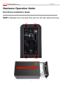
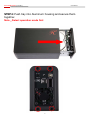
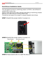
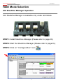
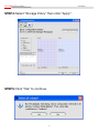
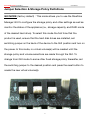
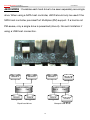
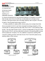
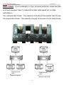
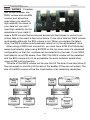
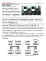
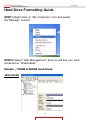
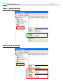
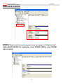
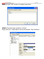
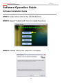
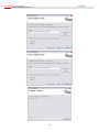
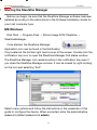
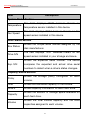
[ R2-RAID ] Server RAID System User Manual Include Hardware Installation Guide Operation Guide HDD Formatting Guide Software Installation Guide Operation Notice: In avoidance of HDD's temperature going too high, be sure to turn on the FAN. Thank you for purchasing a quality Rosewill Product. Please register your product at : www.rosewill.com/ for complete warranty information and future support for your product. Server RAID System [ R2-RAID ] User Manual CONTENTS Hardware Operation Guide…………..............……………………3 Hard Drives Installation Guide……………………………..………3 Mode Selection & Operation Guide…………………….…..……..6 Raid Mode Selection….............…………………………….……...7 Gui Steelvine Manager Operation………….............……….…….7 Jumper Selection & Storage Policy Definitions……..............…..9 Hard Drive Formatting Guide………………………….................16 Software Operation Guide…………………………......................23 Software Installation Guide.........................................................23 Starting The Steelvine Manager..................................................25 Introducing The Steelvine Manager............................................26 1 Server RAID System [ R2-RAID ] User Manual About the 3.5” Dual SATA Disk Enclosure E F D C B A G Front View A C E G Rear View Fan Power Switch Fan Switch LED Indicator B eSATA Connector D USB Connector F Power Adapter Socket 2 Server RAID System [ R2-RAID ] User Manual Hardware Operation Guide Hard Drives Installation Guide STEP1: Release the 4 screws then pull out the rear panel and tray. 3 Server RAID System [ R2-RAID ] User Manual STEP2: Place the two HDD into the tray. Push the HDD to the end until the HDD is connected with SATA connector. STEP3: Screw the HDD on the tray both sides. 4 Server RAID System [ R2-RAID ] User Manual STEP4: Push tray into Aluminum housing and secure them together. Note:Select operation mode first 5 Server RAID System [ R2-RAID ] User Manual Hard Drives Installation Guide You may select function by switching jumper on PCB or use software to operate (GUI mode only). Always press reset button after changing the setting of switching jumpers. Backup your data before formatting hard drives. The device can support two equal or unequal capacity hard drives. STEP1: Switch the power button to power on. STEP2: Switch the power button to power on. Reset Button Switching Jumper STEP3: Press reset button to reset the device. 6 Server RAID System [ R2-RAID ] User Manual RAID Mode Selection GUI SteelVine Manager Operation GUI SteelVine Manager is available only under GUI Mode. STEP1: Install SteelVine Manager (Please refer to page 23). STEP2: Start the SteelVine Manager (Please refer to page 25). STEP3: Click on “Configure Box” icon. 7 Server RAID System [ R2-RAID ] User Manual STEP4: Select “Storage Policy” then click “Apply”. STEP5: Click “Yes” to continue. 8 Server RAID System [ R2-RAID ] User Manual Jumper Selection & Storage Policy Definitions GUI MODE (factory default):This mode allows you to use the SteelVine Manager GUI to configure the storage policy and other settings as well as monitor the status of the appliance (i.e., storage capacity, and RAID mode of the desired hard drive). To select this mode the first time that the product is used, ensure that the hard disk drives are installed, set switching jumper on the back of the device to the GUI position and turn on the power. In this mode, no virtual volume(s) will be created until the storage policy and volume selections are made through the GUI. To change from GUI mode to some other fixed storage policy thereafter, set the switching jumper to the desired position and press the reset button to create the new virtual volume(s). 9 Server RAID System [ R2-RAID ] User Manual JBOD MODE:It enables each hard drive to be seen separately as a single drive. When using a SATA host controller, JBOD should only be used if the SATA host controller provides Port Multiplier (PM) support. If a host is not PM-aware, only a single drive is presented (drive A). No such limitation if using a USB host connection. Volume A Volume A Volume B HD3206SRD Port 0 Port 1 Drive A Volume B HD3206SRD Port 0 Port 1 Drive B Drive A Equal hard drives Drive B Unequal hard drives 10 Server RAID System [ R2-RAID ] User Manual BIG MODE:It concatenates a series of physical hard drives as a single large volume; resulting in a seamless expansion of virtual volumes beyond the physical limitations of singularly connected hard drives. Hard drive A and B are concatenated into a single virtual volume in the figure below with a storage capacity that is equal to the sum of each of the physical hard drives A and B. It is also possible to create a BIG volume using only a single hard disk drive connected to Port 0, and then increase the storage capacity of the volume later by adding another hard disk drive to Port 1 and pressing reset button. The new disk blocks of Port 1 will be concatenated to the end of the disk blocks of Port 0, and any data that is stored on the existing BIG volume will be preserved. However, it is not possible to expand an existing BIG volume by adding another hard disk drive to Port 0 and still preserve any existing data on that volume. Big 500GB Big 1000GB HD3206SRD Port 0 Port 1 HD3206SRD Port 0 Port 1 Drive A 250GB + Drive A 250GB Drive A 250GB Equal hard drives + Drive A 750GB Unequal hard drives 11 Server RAID System [ R2-RAID ] User Manual RAID 0 (Fast):It’s a combination of two physical partitions, where the data is striped between them. It presents the best data speed but no data redundancy. Two unequal hard drives:The capacity is double of the smaller hard drives. Two equal hard drives:The capacity is equal to the sum of both hard drives. Fast 500GB Fast 500GB HD3206SRD Port 0 Port 1 HD3206SRD Port 0 Port 1 Drive A 250GB Drive B 250GB Drive A 250GB Striping across disks Drive B 750GB Striping across disks Equal hard drives Unequal hard drives 12 Server RAID System [ R2-RAID ] User Manual RAID 1 (Safe):It allows the device automatically to copy data to both hard drives. It stores all data in duplicate on separate drives to protect against data loss due to drive failure. It provides the highest level of data protection for critical data that you cannot afford to lose if a hard drive fails. The capacity is equal to the smaller of the two hard drives. If one drive fails, the SAFE volume is still usable, but it is in a vulnerable state because its mirrored hard drive is inaccessible. When the offline drive comes back online, the appliance begins a rebuild process immediately to restore data redundancy. Although the volume remains available during the rebuild process, the volume is susceptible to data loss through damage to the remaining drive until redundancy is restored at the end of the rebuild and verification process. Host access takes precedence over the rebuild process. If you continue to use the SAFE volume during the rebuild, the rebuild process will take a longer time to complete, and the host data transfer performance will also be affected. Safe 250GB Safe 250GB HD3206SRD Port 0 Port 1 HD3206SRD Port 0 Port 1 Drive A 250GB Drive A 250GB Drive B 250GB Equal hard drives Unequal hard drives 13 Drive B 750GB Server RAID System [ R2-RAID ] User Manual RAID / SAFE33:It creates two virtual volumes; one SAFE volume and one BIG volume, and should be used when you need the high reliability for some of your data but you don’t need high reliability for the remainder of your data. It uses a SAFE volume that is mirrored across two hard drives to protect your critical data in the event a hard drive failure. If one drive fails the SAFE volume is retrievable although the BIG volume is not. When you replace the failed drive, the SAFE volume is automatically rebuilt on to the replacement drive. When using a SATA host connection, you must have a PM (Port Multiplier) aware host adapter when using SAFE33 on the top level node of a cascaded configuration so that ALL volumes can be detected by the host. If your SATA host adaptor is not PM aware, then ONLY the SAFE volume will be detected and the BIG volume will not be accessible. No such limitation exists when using a USB host connection. The size of the SAFE volume will be one-third of the size of one hard drive (if they are equal) or one-third of the size of the smaller (if they are not equal.) The size of the BIG volume will be the combination of all remaining capacities. Safe 83GB Big 334GB Safe 83GB HD3206SRD Port 0 Port 1 Drive A 250GB Big 834GB HD3206SRD Port 0 Port 1 Drive A 250GB Drive B 250GB Equal hard drives Drive B 750GB Unequal hard drives 14 Server RAID System [ R2-RAID ] User Manual RAID / SAFE50:It creates two virtual volumes; one SAFE volume and one BIG volume, and should be used when you need the high reliability for some of your data but you don’t need high reliability for the remainder of your data. It reduces the cost of additional hard drives in operations where non-critical data could be lost without severe consequences. If one drive fails the SAFE volume is retrievable although the BIG volume is not. When you replace the failed drive, the SAFE volume is automatically rebuilt on to the replacement drive. When using a SATA host connection, you must have a PM (Port Multiplier) aware host adapter when using SAFE50 on the top level node of a cascaded configuration so that ALL volumes can be detected by the host. If your SATA host adaptor is not PM aware, then ONLY the SAFE volume will be detected and the BIG volume will not be accessible. No such limitation exists when using a USB host connection. The size of the SAFE volume will be one-half of the size of one hard drive (if they are equal) or one-half of the size of the smaller (if they are not equal). The size of the BIG volume will be the combination of all remaining capacities. Safe 125GB Big 250GB Safe 125GB HD3206SRD Port 0 Port 1 Drive A 250GB Drive B 750GB HD3206SRD Port 0 Port 1 Drive A 250GB Drive B 250GB Equal hard drives Unequal hard drives 15 Drive B 750GB Server RAID System [ R2-RAID ] User Manual Hard Drive Formatting Guide STEP1: Right-click on “My Computer” icon and select the“Manage” column. STEP2: Select “Disk Management” and you will see your hard drives show “Unallocated”. Sample:750GB & 250GB hard drives. JBOD MODE 16 Server RAID System [ R2-RAID ] User Manual BIG MODE RAID 0 (FAST) MODE 17 Server RAID System [ R2-RAID ] User Manual RAID 1 (SAFE) MODE RAID/SAFE 33 MODE 18 Server RAID System [ R2-RAID ] User Manual RAID/SAFE 50 MODE STEP3: Right-click the red-squared block and selects “Initialize Disk”. Take JBOD MODE for example. (one 750GB HDD & one 250GB hard drives) 19 Server RAID System [ R2-RAID ] User Manual STEP4: Press “OK” button to initialize hard drive. STEP5: The hard drive will show “Online”. Right-click the “Unallocated” block and selects “New Partition”. 20 Server RAID System [ R2-RAID ] User Manual STEP6: The “New Partition Wizard” will appear. Please follow the instruction of the wizard to complete the partition. 21 Server RAID System [ R2-RAID ] User Manual STEP7: When new partition is completed, the hard drive will be recognized as a “New Volume”. STEP8: Format the other hard drive in the same way. 22 Server RAID System [ R2-RAID ] User Manual Software Operation Guide Software Installation Guide STEP1: Insert driver CD to the CD-ROM drive. STEP2: Select “Install GUI” icon to install the driver. STEP3: Please follow the wizard to complete. 23 Server RAID System [ R2-RAID ] User Manual 24 cS e oe a g t a P ise S t o rg m a lF Server RAID System [ R2-RAID ] User Manual Starting the SteelVine Manager Before you begin, be sure that the SteelVine Manager software has been installed according to the instructions in the Software Installation Guide for your host computer type. MS Windows Click Start → Program Files → Silicon Image 57XX SteelVine → SteelVineManager. Once started, the SteelVine Manager Application icon can be found in the Notification Tray located at the bottom right hand corner of the screen. Double click the notification tray icon to open the SteelVine Manager GUI status window. The SteelVine Manager icon remains active in the notification tray even if you close the SteelVine Manager window. It can be closed by right-clicking on the icon and selecting “Exit”. i Select menu options and follow the instructions in the remainder of this guide to configure the device. When prompted, enter the administrative password (default password is admin). 25 Server RAID System [ R2-RAID ] User Manual Introducing the SteelVine Manager The SteelVine Manager starts with the Status window visible so you can monitor the device. The Status-only mode is entered when the switching jumper is in the JBOD, BIG, RAID 0, RAID 1, SAFE33, or SAFE50 mode. In Status only mode, you are not permitted to change the configuration from the GUI. The only possible way to change the configuration is to change the switching jumper. Configure Popups View Policies Configure Email Notification Event Log Schedule Disk Verify Specify Firmware Backup Button System Status Configure Box Drive Status Box Serial Number Drive Information Capacity Information Volume Information 26 Server RAID System [ R2-RAID ] User Manual Item Description System Status Section Temperature Fan Speed The field displays “N/A” because there’s no temperature sensor installed in this device. The field displays “N/A” because there’s no fan speed sensor installed in this device. Drive Status Section Box Status Drive S/N Shows the unique serial number assigned by the disk manufacturer. The field displays “N/A” because there’s no fan speed sensor installed in your storage enclosure. Shows the expected serial number. The device Exp. S/N compares the expected and actual drive serial numbers to detect when a drive’s status changes. Capacity Status Section Policy Shows the storage policy configured for each volume. Total Shows the combined capacity of the volume. Drive # Shows capacity information for each hard drive. Capacity Volume Shows the amount of storage space available on each hard drive. Shows the total volume capacity and the drive capacities assigned to each volume. 27 Server RAID System [ R2-RAID ] Item Tooltip User Manual Description Toolbar Buttons on Status Section Opens the Basic Configuration Configure Box Wizard. (appears only when using GUI Configuration mode) Schedule Disk Verify Schedule a disk Verify activity. (appears only when one or more SAFE volumes exist) Configure Pop-Ups Configure the Pop-Up messages. Shows the Rebuild Policy settings View Policy that are defined by the GPI pins Settings (appears only when one or more SAFE volumes exist) Email Notification Show Event Log Configure the operation of email message notification. View the Event Log. View the current version or download Specify Firmware an updated version of the SteelVine Storage Processor firmware. Backup Button Useless on this device. 28